appendix a _ turbine manufacturer technical specification_2.75mw
TRANSCRIPT
7/27/2019 Appendix a _ Turbine Manufacturer Technical Specification_2.75MW
http://slidepdf.com/reader/full/appendix-a-turbine-manufacturer-technical-specification275mw 1/82
General Electric 2.75 MW Turbines
7/27/2019 Appendix a _ Turbine Manufacturer Technical Specification_2.75MW
http://slidepdf.com/reader/full/appendix-a-turbine-manufacturer-technical-specification275mw 2/82
GE Power & WaterRenewable Energy
GEA18379A (05/2011)
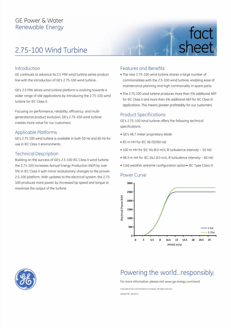
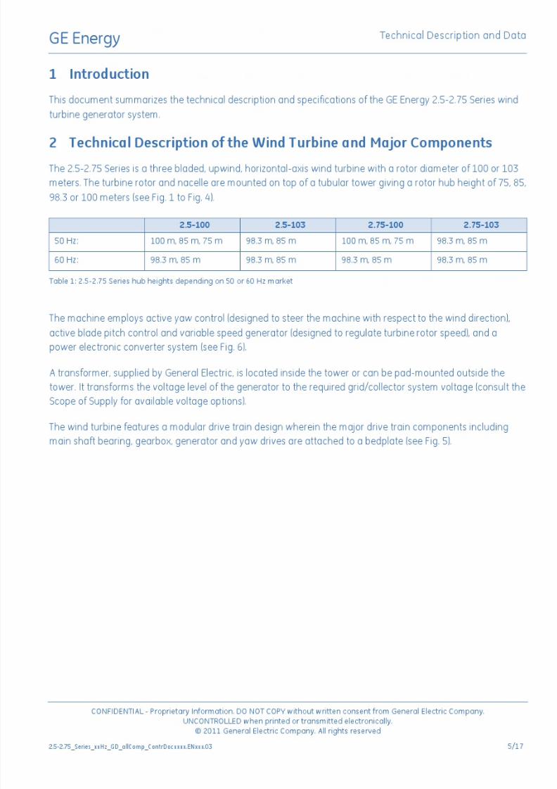
IntroductionGE continues to advance its 2.5 MW wind turbine series product
line with the introduction of GE’s 2.75-100 wind turbine.
GE’s 2.5 MW series wind turbine platform is evolving towards a
wider range of site applications by introducing the 2.75-100 wind
turbine for IEC Class II.
Focusing on performance, reliability, efficiency, and multi-
generational product evolution, GE’s 2.75-100 wind turbine
creates more value for our customers.
Applicable PlatformsGE’s 2.75-100 wind turbine is available in both 50 Hz and 60 Hz for
use in IEC Class II environments.
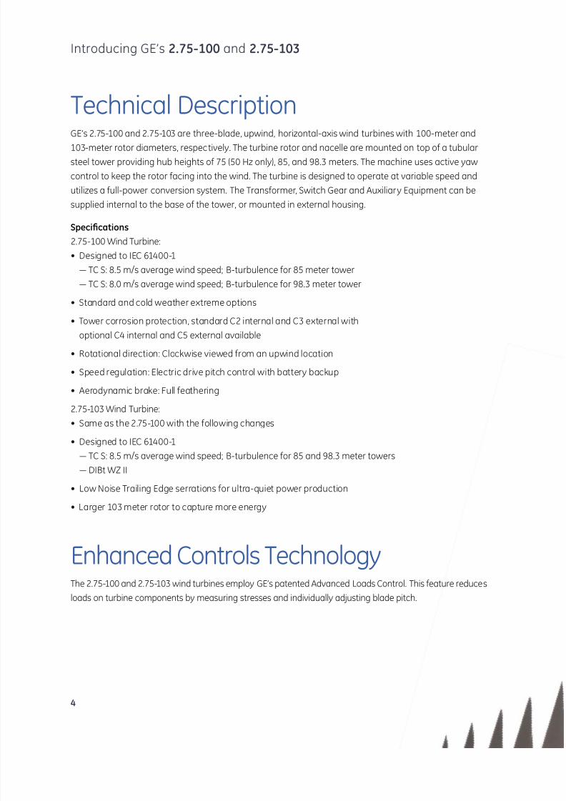
Technical DescriptionBuilding on the success of GE’s 2.5-100 IEC Class II wind turbine,
the 2.75-100 increases Annual Energy Production (AEP) by over
5% in IEC Class II with minor evolutionary changes to the proven2.5-100 platform. With updates to the electrical system, the 2.75-
100 produces more power by increased tip speed and torque to
maximize the output of the turbine.
2.75-100 Wind Turbine
factsheet
0
500
1000
1500
2000
2500
3000
0 3 5.5 8 10.5 13 15.5 18 20.5 23
2.5xl
2.75xl
0
500
1000
1500
2000
2500
3000
0 3 5.5 8 10.5 13 15.5 18 20.5 23
2.5xl
2.75xl
E l e c t r i c a l P o w e r ( k W )
AMWS (m/s)
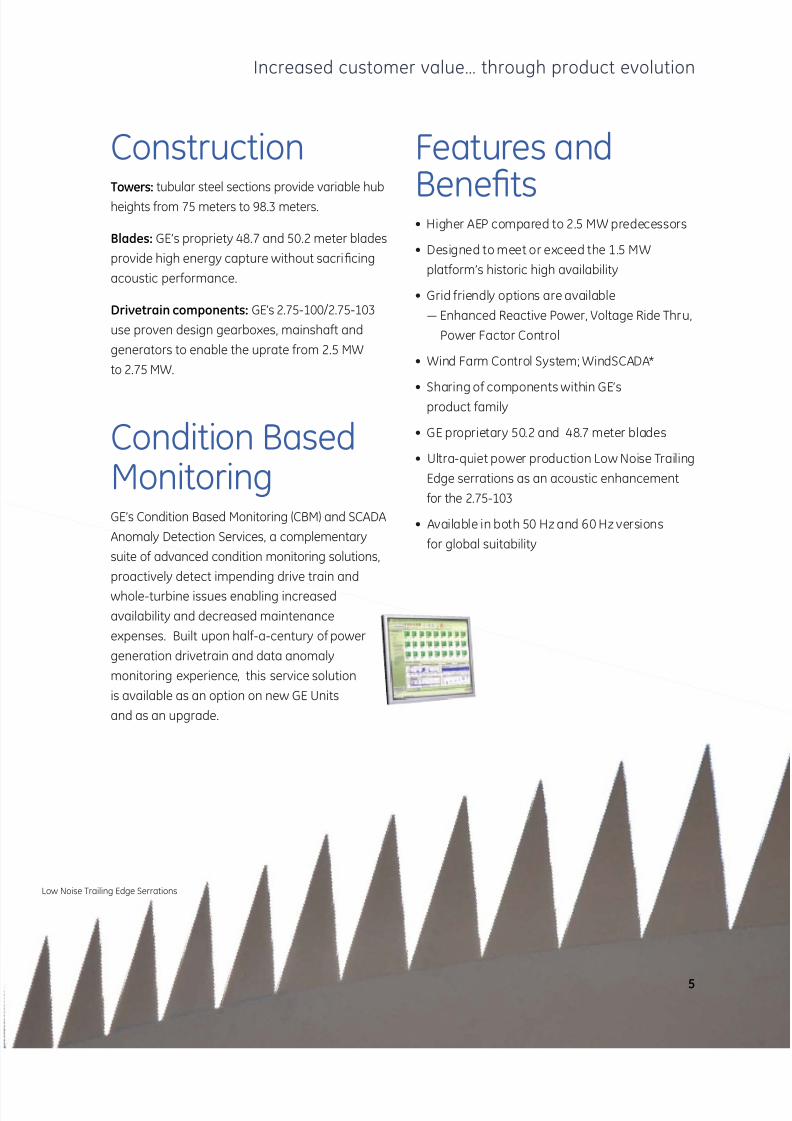
Features and Benefits• he new .75-100 wind turbine shares a large number of
commonalities with the 2.5-100 wind turbine, enabling ease of
maintenance planning and high commonality in spare parts.
• The 2.75-100 wind turbine produces more than 5% additional AEP
for IEC Class II and more than 4% additional AEP for IEC Class III
applications. This means greater profitability for our customers.
Product SpecificationsGE’s 2.75-100 wind turbine offers the following technical
specifications:
• Es 8.7 meter proprietary blade
• 85 m HH for IEC IIb 50/60 Hz
• 100 m HH for IEC IIIs 8.0 m/s turbulence intensity 50 Hz
• 8. m HH for IEC IIIs 8.0 m/s turbulence intensity 60 Hz
• Cold weather extreme configuration option• IEC ype Class III
Power Curve
Powering the world…responsibly.For more information, please visit www.ge-energy.com/wind
Copyright © 2011 General Electric Company. All rights reserved..
7/27/2019 Appendix a _ Turbine Manufacturer Technical Specification_2.75MW
http://slidepdf.com/reader/full/appendix-a-turbine-manufacturer-technical-specification275mw 3/82

7/27/2019 Appendix a _ Turbine Manufacturer Technical Specification_2.75MW
http://slidepdf.com/reader/full/appendix-a-turbine-manufacturer-technical-specification275mw 4/82
7/27/2019 Appendix a _ Turbine Manufacturer Technical Specification_2.75MW
http://slidepdf.com/reader/full/appendix-a-turbine-manufacturer-technical-specification275mw 5/82
7/27/2019 Appendix a _ Turbine Manufacturer Technical Specification_2.75MW
http://slidepdf.com/reader/full/appendix-a-turbine-manufacturer-technical-specification275mw 6/82
7/27/2019 Appendix a _ Turbine Manufacturer Technical Specification_2.75MW
http://slidepdf.com/reader/full/appendix-a-turbine-manufacturer-technical-specification275mw 7/82

7/27/2019 Appendix a _ Turbine Manufacturer Technical Specification_2.75MW
http://slidepdf.com/reader/full/appendix-a-turbine-manufacturer-technical-specification275mw 8/82

7/27/2019 Appendix a _ Turbine Manufacturer Technical Specification_2.75MW
http://slidepdf.com/reader/full/appendix-a-turbine-manufacturer-technical-specification275mw 9/82
7/27/2019 Appendix a _ Turbine Manufacturer Technical Specification_2.75MW
http://slidepdf.com/reader/full/appendix-a-turbine-manufacturer-technical-specification275mw 10/82
enotes trademarsof eneral Electric Company.
© 2011 General Electric Company. All rights reserved.
GEA18657 (04/2011)
Powering the world…responsibly.or more information please visit www.ge-energy.com/wind.
7/27/2019 Appendix a _ Turbine Manufacturer Technical Specification_2.75MW
http://slidepdf.com/reader/full/appendix-a-turbine-manufacturer-technical-specification275mw 11/82

7/27/2019 Appendix a _ Turbine Manufacturer Technical Specification_2.75MW
http://slidepdf.com/reader/full/appendix-a-turbine-manufacturer-technical-specification275mw 12/82
7/27/2019 Appendix a _ Turbine Manufacturer Technical Specification_2.75MW
http://slidepdf.com/reader/full/appendix-a-turbine-manufacturer-technical-specification275mw 13/82

7/27/2019 Appendix a _ Turbine Manufacturer Technical Specification_2.75MW
http://slidepdf.com/reader/full/appendix-a-turbine-manufacturer-technical-specification275mw 14/82
7/27/2019 Appendix a _ Turbine Manufacturer Technical Specification_2.75MW
http://slidepdf.com/reader/full/appendix-a-turbine-manufacturer-technical-specification275mw 15/82

7/27/2019 Appendix a _ Turbine Manufacturer Technical Specification_2.75MW
http://slidepdf.com/reader/full/appendix-a-turbine-manufacturer-technical-specification275mw 16/82
7/27/2019 Appendix a _ Turbine Manufacturer Technical Specification_2.75MW
http://slidepdf.com/reader/full/appendix-a-turbine-manufacturer-technical-specification275mw 17/82
7/27/2019 Appendix a _ Turbine Manufacturer Technical Specification_2.75MW
http://slidepdf.com/reader/full/appendix-a-turbine-manufacturer-technical-specification275mw 18/82

7/27/2019 Appendix a _ Turbine Manufacturer Technical Specification_2.75MW
http://slidepdf.com/reader/full/appendix-a-turbine-manufacturer-technical-specification275mw 19/82
7/27/2019 Appendix a _ Turbine Manufacturer Technical Specification_2.75MW
http://slidepdf.com/reader/full/appendix-a-turbine-manufacturer-technical-specification275mw 20/82
7/27/2019 Appendix a _ Turbine Manufacturer Technical Specification_2.75MW
http://slidepdf.com/reader/full/appendix-a-turbine-manufacturer-technical-specification275mw 21/82
7/27/2019 Appendix a _ Turbine Manufacturer Technical Specification_2.75MW
http://slidepdf.com/reader/full/appendix-a-turbine-manufacturer-technical-specification275mw 22/82
7/27/2019 Appendix a _ Turbine Manufacturer Technical Specification_2.75MW
http://slidepdf.com/reader/full/appendix-a-turbine-manufacturer-technical-specification275mw 23/82

7/27/2019 Appendix a _ Turbine Manufacturer Technical Specification_2.75MW
http://slidepdf.com/reader/full/appendix-a-turbine-manufacturer-technical-specification275mw 24/82
7/27/2019 Appendix a _ Turbine Manufacturer Technical Specification_2.75MW
http://slidepdf.com/reader/full/appendix-a-turbine-manufacturer-technical-specification275mw 25/82

7/27/2019 Appendix a _ Turbine Manufacturer Technical Specification_2.75MW
http://slidepdf.com/reader/full/appendix-a-turbine-manufacturer-technical-specification275mw 26/82
7/27/2019 Appendix a _ Turbine Manufacturer Technical Specification_2.75MW
http://slidepdf.com/reader/full/appendix-a-turbine-manufacturer-technical-specification275mw 27/82

7/27/2019 Appendix a _ Turbine Manufacturer Technical Specification_2.75MW
http://slidepdf.com/reader/full/appendix-a-turbine-manufacturer-technical-specification275mw 28/82
GE Energy
GE imagination at work
© 2011 General Electric Company. All rights reserved.
Technical Documentation
Wind Turbine Generator Systems2.75 50 Hz and 60 Hz
Electric Grid Data
according to IEC
7/27/2019 Appendix a _ Turbine Manufacturer Technical Specification_2.75MW
http://slidepdf.com/reader/full/appendix-a-turbine-manufacturer-technical-specification275mw 29/82
GE Energy
GE imagination at work2.75_xxHz_EGD_allComp_IECxxxxxxxxx.ENxxx.00a.doc.
Gepower.com
Visit us atwww.gewindenergy.com
All technical data is subject to change in line with ongoing technical development!
Copyright and patent rights
This document is to be treated confidentially. It may only be made accessible to authorized persons. It may only
be made available to third parties with the expressed written consent of General Electric Company.
All documents are copyrighted within the meaning of the Copyright Act. The transmission and reproduction of the
documents, also in extracts, as well as the exploitation and communication of the contents are not allowed
without express written consent. Contraventions are liable to prosecution and compensation for damage. We
reserve all rights for the exercise of commercial patent rights.
© 2010 General Electric Company. All rights reserved.
GE and are trademarks and service marks of General Electric Company.
Other company or product names mentioned in this document may be trademarks or registered trademarks of
their respective companies.
7/27/2019 Appendix a _ Turbine Manufacturer Technical Specification_2.75MW
http://slidepdf.com/reader/full/appendix-a-turbine-manufacturer-technical-specification275mw 30/82
GE Energy Electric Grid Data
CONFIDENTIAL - Proprietary Information. DO NOT COPY without written consent from General Electric Company.UNCONTROLLED when printed or transmitted electronically.
© 2011 General Electric Company. All rights reserved
2.75_xxHz_EGD_allComp_IECxxxxxxxxx.ENxxx.00a.doc
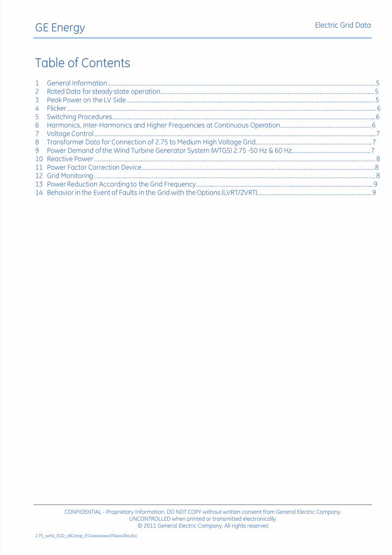
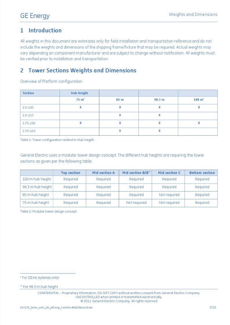
Table of Contents
1 General Information .................................................................................................................................................................................................. 52 Rated Data for steady state operation ........................................................................................................................................................... 5
3 Peak Power on the LV Side .................................................................................................................................................................................... 54 Flicker ................................................................................................................................................................................................................................ 65 Switching Procedures ............................................................................................................................................................................................... 66 Harmonics, Inter-Harmonics and Higher Frequencies at Continuous Operation .................................................................. 67 Voltage Control ............................................................................................................................................................................................................ 78 Transformer Data for Connection of 2.75 to Medium High Voltage Grid .................................................................................... 79 Power Demand of the Wind Turbine Generator System (WTGS) 2.75 -50 Hz & 60 Hz ......................................................... 710 Reactive Power ............................................................................................................................................................................................................ 811 Power Factor Correction Device......................................................................................................................................................................... 812 Grid Monitoring ............................................................................................................................................................................................................ 813 Power Reduction According to the Grid Frequency ................................................................................................................................ 9
14 Behavior in the Event of Faults in the Grid with the Options (LVRT/ZVRT) ................................................................................... 9
7/27/2019 Appendix a _ Turbine Manufacturer Technical Specification_2.75MW
http://slidepdf.com/reader/full/appendix-a-turbine-manufacturer-technical-specification275mw 31/82
GE Energy Electric Grid Data
CONFIDENTIAL - Proprietary Information. DO NOT COPY without written consent from General Electric Company.UNCONTROLLED when printed or transmitted electronically.
© 2011 General Electric Company. All rights reserved
2.75_xxHz_EGD_allComp_IECxxxxxxxxx.ENxxx.00a.doc 5/9
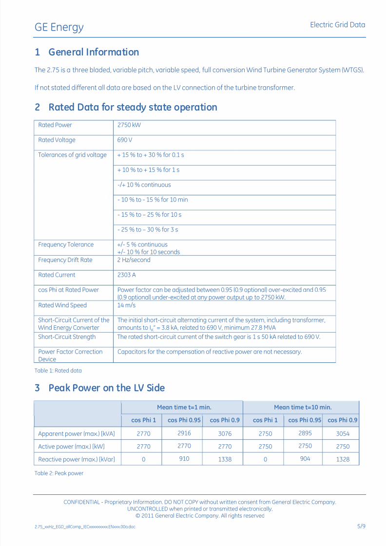
1 General Information
The 2.75 is a three bladed, variable pitch, variable speed, full conversion Wind Turbine Generator System (WTGS).
If not stated different all data are based on the LV connection of the turbine transformer.
2 Rated Data for steady state operation
Rated Power 2750 kW
Rated Voltage 690 V
Tolerances of grid voltage + 15 % to + 30 % for 0.1 s
+ 10 % to + 15 % for 1 s
-/+ 10 % continuous
- 10 % to - 15 % for 10 min
- 15 % to 25 % for 10 s
- 25 % to 30 % for 3 s
Frequency Tolerance +/- 5 % continuous+/- 10 % for 10 seconds
Frequency Drift Rate 2 Hz/second
Rated Current 2303 A
cos Phi at Rated Power Power factor can be adjusted between 0.95 (0.9 optional) over-excited and 0.95(0.9 optional) under-excited at any power output up to 2750 kW.
Rated Wind Speed 14 m/s
Short-Circuit Current of theWind Energy Converter
The initial short-circuit alternating current of the system, including transformer,amounts to IK = 3.8 kA, related to 690 V, minimum 27.8 MVA
Short-Circuit Strength The rated short-circuit current of the switch gear is 1 s 50 kA related to 690 V.
Power Factor CorrectionDevice
Capacitors for the compensation of reactive power are not necessary.
Table 1: Rated data
3 Peak Power on the LV Side
Mean time t=1 min. Mean time t=10 min.
cos Phi 1 cos Phi 0.95 cos Phi 0.9 cos Phi 1 cos Phi 0.95 cos Phi 0.9
Apparent power (max.) [kVA] 2770 2916 3076 2750 2895 3054
Active power (max.) [kW] 2770 2770 2770 2750 2750 2750
Reactive power (max.) [kVar] 0 910 1338 0 904 1328
Table 2: Peak power
7/27/2019 Appendix a _ Turbine Manufacturer Technical Specification_2.75MW
http://slidepdf.com/reader/full/appendix-a-turbine-manufacturer-technical-specification275mw 32/82
GE Energy Electric Grid Data
CONFIDENTIAL - Proprietary Information. DO NOT COPY without written consent from General Electric Company.UNCONTROLLED when printed or transmitted electronically.
© 2011 General Electric Company. All rights reserved
6/9 2.75_xxHz_EGD_allComp_IECxxxxxxxxx.ENxxx.00a.doc
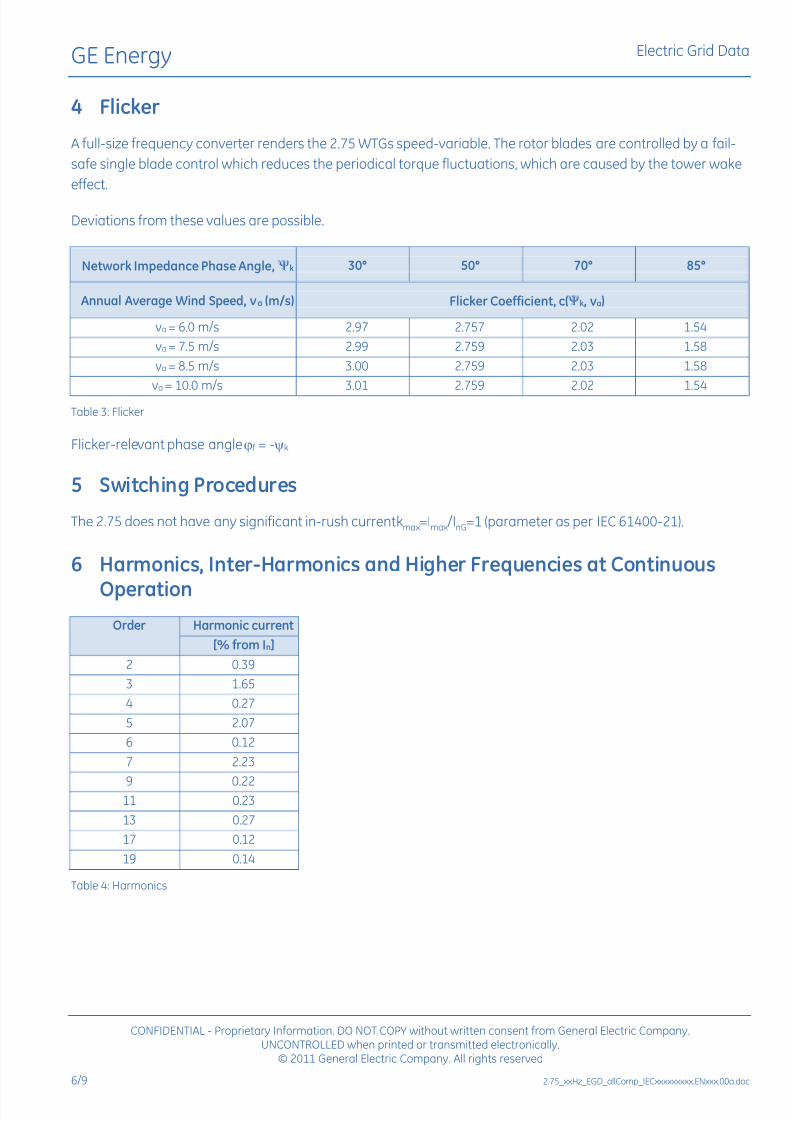
4 Flicker
A full-size frequency converter renders the 2.75 WTGs speed-variable. The rotor blades are controlled by a fail-
safe single blade control which reduces the periodical torque fluctuations, which are caused by the tower wake
effect.
Deviations from these values are possible.
Network Impedance Phase Angle, k 30° 50° 70° 85°
Annual Average Wind Speed, va (m/s) Flicker Coefficient, c(k, va)
va = 6.0 m/s 2.97 2.757 2.02 1.54
va = 7.5 m/s 2.99 2.759 2.03 1.58
va = 8.5 m/s 3.00 2.759 2.03 1.58
va = 10.0 m/s 3.01 2.759 2.02 1.54
Table 3: Flicker
Flicker-relevant phase angle f = -k
5 Switching Procedures
The 2.75 does not have any significant in-rush current kmax=Imax/InG=1 (parameter as per IEC 61400-21).
6 Harmonics, Inter-Harmonics and Higher Frequencies at Continuous
OperationOrder Harmonic current
[% from In]
2 0.39
3 1.65
4 0.27
5 2.07
6 0.12
7 2.23
9 0.2211 0.23
13 0.27
17 0.12
19 0.14
Table 4: Harmonics
7/27/2019 Appendix a _ Turbine Manufacturer Technical Specification_2.75MW
http://slidepdf.com/reader/full/appendix-a-turbine-manufacturer-technical-specification275mw 33/82
GE Energy Electric Grid Data
CONFIDENTIAL - Proprietary Information. DO NOT COPY without written consent from General Electric Company.UNCONTROLLED when printed or transmitted electronically.
© 2011 General Electric Company. All rights reserved
2.75_xxHz_EGD_allComp_IECxxxxxxxxx.ENxxx.00a.doc 7/9
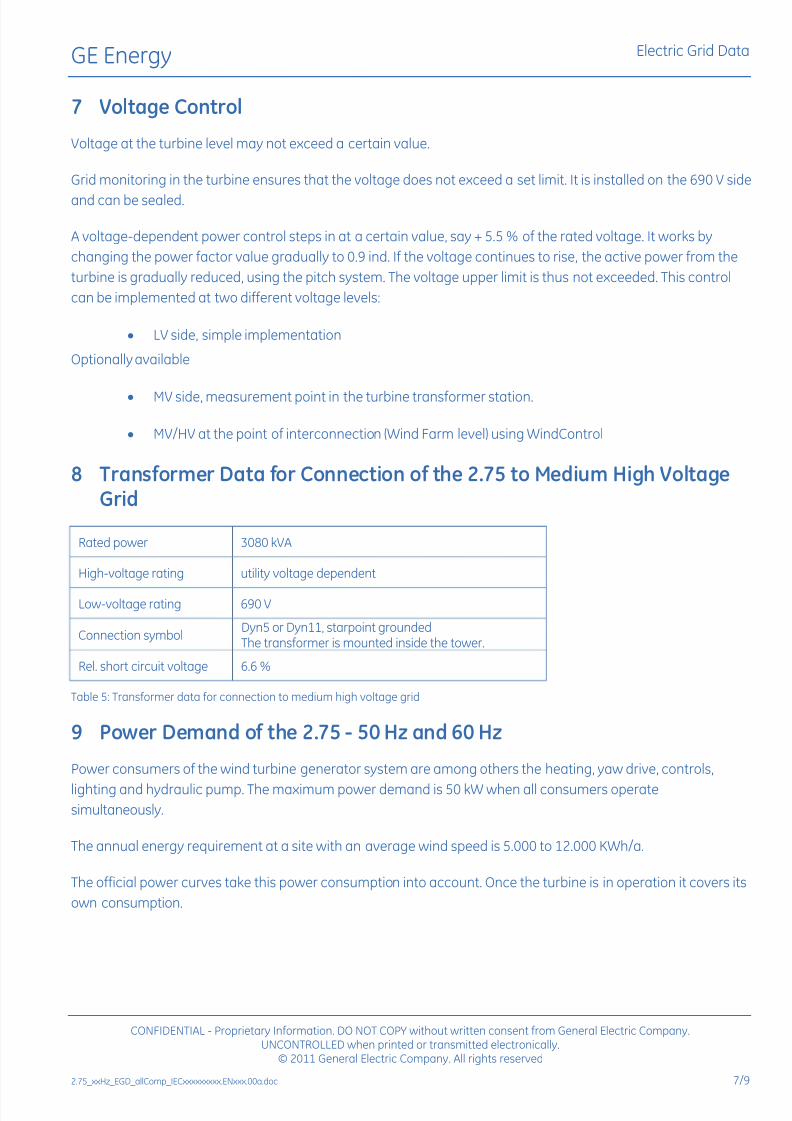
7 Voltage Control
Voltage at the turbine level may not exceed a certain value.
Grid monitoring in the turbine ensures that the voltage does not exceed a set limit. It is installed on the 690 V side
and can be sealed.
A voltage-dependent power control steps in at a certain value, say + 5.5 % of the rated voltage. It works by
changing the power factor value gradually to 0.9 ind. If the voltage continues to rise, the active power from the
turbine is gradually reduced, using the pitch system. The voltage upper limit is thus not exceeded. This control
can be implemented at two different voltage levels:
LV side, simple implementation
Optionally available
MV side, measurement point in the turbine transformer station.
MV/HV at the point of interconnection (Wind Farm level) using WindControl
8 Transformer Data for Connection of the 2.75 to Medium High VoltageGrid
Rated power 3080 kVA
High-voltage rating utility voltage dependent
Low-voltage rating 690 V
Connection symbolDyn5 or Dyn11, starpoint groundedThe transformer is mounted inside the tower.
Rel. short circuit voltage 6.6 %
Table 5: Transformer data for connection to medium high voltage grid
9 Power Demand of the 2.75 - 50 Hz and 60 Hz
Power consumers of the wind turbine generator system are among others the heating, yaw drive, controls,
lighting and hydraulic pump. The maximum power demand is 50 kW when all consumers operatesimultaneously.
The annual energy requirement at a site with an average wind speed is 5.000 to 12.000 KWh/a.
The official power curves take this power consumption into account. Once the turbine is in operation it covers its
own consumption.

7/27/2019 Appendix a _ Turbine Manufacturer Technical Specification_2.75MW
http://slidepdf.com/reader/full/appendix-a-turbine-manufacturer-technical-specification275mw 34/82
GE Energy Electric Grid Data
CONFIDENTIAL - Proprietary Information. DO NOT COPY without written consent from General Electric Company.UNCONTROLLED when printed or transmitted electronically.
© 2011 General Electric Company. All rights reserved
8/9 2.75_xxHz_EGD_allComp_IECxxxxxxxxx.ENxxx.00a.doc
10 Reactive Power
A cos (power factor) and a VAR specification can be selected between for the reactive power of the 2.75. The
power factor of the 2.75 can be set from cos 0.95 (904 kVAR) inductive (optional cos 0.9 (1328 kVAR) and cos
0.95 (904 kVAR) capacitive (optional cos 0.9 (1328 kVAR). In standard VAR mode the wind turbine is capable for
at least VARs according the cos curve.
The VAR specification provides the option of a WindFree Reactive Power function. This means that the turbine
can also make reactive power (up to 1328 kVAR) available as a voltage buffering during the full operational range
(0-2750 kW), even during calm periods or strong winds.
Fig. 1: VAR Curve
11 Power Factor Correction Device
Capacitors for the compensation of reactive power are not necessary.
12 Grid Monitoring
The turbine is equipped with a line protection relay the trigger values of which can be set in compliance with the
utility company specifications and within the applicable limits. The relay is connected at the secondary side of the
transformer.
7/27/2019 Appendix a _ Turbine Manufacturer Technical Specification_2.75MW
http://slidepdf.com/reader/full/appendix-a-turbine-manufacturer-technical-specification275mw 35/82
GE Energy Electric Grid Data
CONFIDENTIAL - Proprietary Information. DO NOT COPY without written consent from General Electric Company.UNCONTROLLED when printed or transmitted electronically.
© 2011 General Electric Company. All rights reserved
2.75_xxHz_EGD_allComp_IECxxxxxxxxx.ENxxx.00a.doc 9/9
13 Power Reduction According to the Grid Frequency
An internal (via turbine controller) or external (option: WindControl) reduction of the power output according to
the grid frequency can be adjusted via parameters.
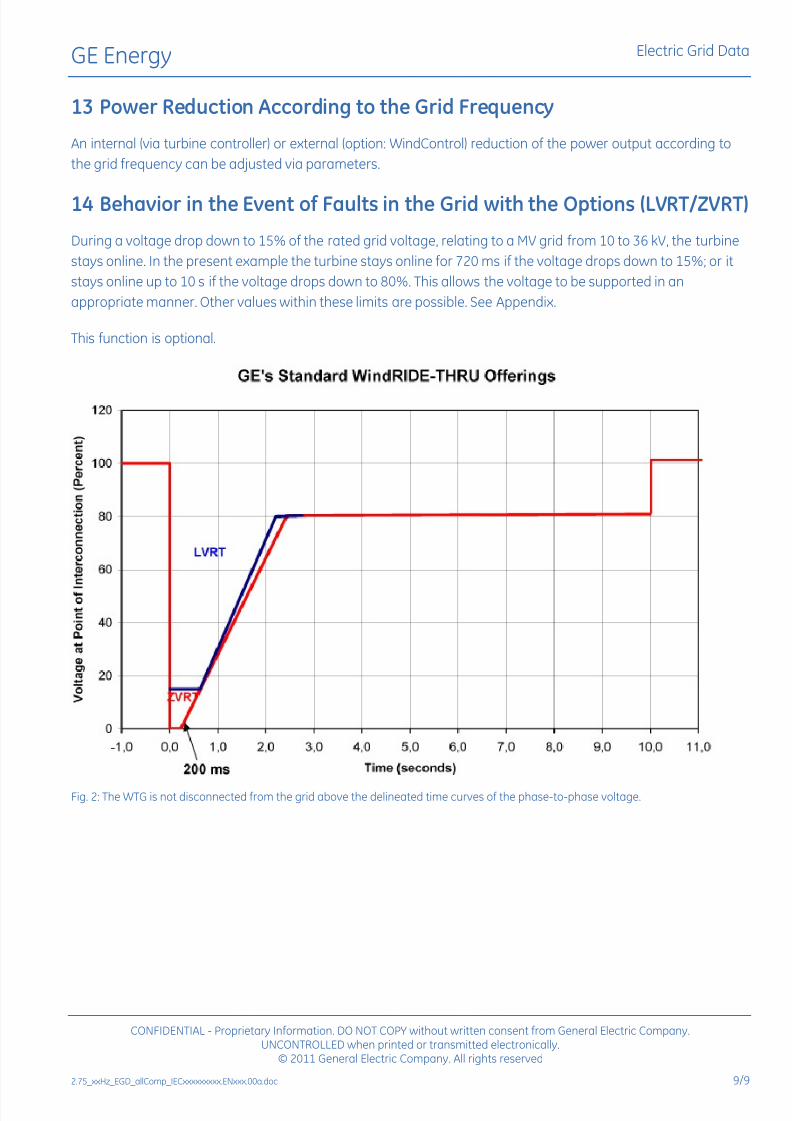
14 Behavior in the Event of Faults in the Grid with the Options (LVRT/ZVRT)
During a voltage drop down to 15% of the rated grid voltage, relating to a MV grid from 10 to 36 kV, the turbine
stays online. In the present example the turbine stays online for 720 ms if the voltage drops down to 15%; or it
stays online up to 10 s if the voltage drops down to 80%. This allows the voltage to be supported in an
appropriate manner. Other values within these limits are possible. See Appendix.
This function is optional.
Fig. 2: The WTG is not disconnected from the grid above the delineated time curves of the phase-to-phase voltage.
7/27/2019 Appendix a _ Turbine Manufacturer Technical Specification_2.75MW
http://slidepdf.com/reader/full/appendix-a-turbine-manufacturer-technical-specification275mw 36/82
GE Energy
imagination at work
© 2011 General Electric Company. All rights reserved.
Commercial Documentation
Wind Turbine Generator Systems2.75-103 - 50 Hz and 60 Hz
Calculated Power Curve andThrust Coefficient
Noise Reduced Operation (NRO)
7/27/2019 Appendix a _ Turbine Manufacturer Technical Specification_2.75MW
http://slidepdf.com/reader/full/appendix-a-turbine-manufacturer-technical-specification275mw 37/82
GE Energy Calculated Power Curve and Thrust Coefficient
imagination at work2.75-103_xxHz_PCD_allComp_NRO_IECxxxxx.ENxxx.01.doc.
Gepower.com
Visit us atwww.gewindenergy.com
All technical data is subject to change in line with ongoing technical development!
Copyright and patent rights
This document is to be treated confidentially. It may only be made accessible to authorized persons. It may
only be made available to third parties with the expressed written consent of General Electric Company.
All documents are copyrighted within the meaning of the Copyright Act. The transmission and reproduction of
the documents, also in extracts, as well as the exploitation and communication of the contents are not allowed
without express written consent. Contraventions are liable to prosecution and compensation for damage. We
reserve all rights for the exercise of commercial patent rights.
© 2011 General Electric Company. All rights reserved.
GE and are trademarks and service marks of General Electric Company.
Other company or product names mentioned in this document may be trademarks or registered trademarks of
their respective companies.

7/27/2019 Appendix a _ Turbine Manufacturer Technical Specification_2.75MW
http://slidepdf.com/reader/full/appendix-a-turbine-manufacturer-technical-specification275mw 38/82
GE Energy Calculated Power Curve and Thrust Coefficient
CONFIDENTIAL - Proprietary Information. DO NOT COPY without written consent from General Electric Company.UNCONTROLLED when printed or transmitted electronically.
© 2011 General Electric Company. All rights reserved
2.75-103_xxHz_PCD_allComp_NRO_IECxxxxx.ENxxx.01.doc
Table of Contents
1 Introduction .................................................................................................................................................................................................................52 Applicability..................................................................................................................................................................................................................53 Noise Reduced Operation Power Performance.......................................................................................................................................64 Noise Reduced Operation Thrust Coefficient............................................................................................................................................8

7/27/2019 Appendix a _ Turbine Manufacturer Technical Specification_2.75MW
http://slidepdf.com/reader/full/appendix-a-turbine-manufacturer-technical-specification275mw 39/82
7/27/2019 Appendix a _ Turbine Manufacturer Technical Specification_2.75MW
http://slidepdf.com/reader/full/appendix-a-turbine-manufacturer-technical-specification275mw 40/82
GE Energy Calculated Power Curve and Thrust Coefficient
CONFIDENTIAL - Proprietary Information. DO NOT COPY without written consent from General Electric Company.UNCONTROLLED when printed or transmitted electronically.
© 2011 General Electric Company. All rights reserved
2.75-103_xxHz_PCD_allComp_NRO_IECxxxxx.ENxxx.01.doc 5/9
1 Introduction
This document provides 2.75-103 wind turbine noise reduced operation (NRO) calculated power curves at an
average air density of 1.225 kg/m3 listed in Table 1 and illustrated in Figure 1.
2 Applicability
The power curve information provided in section 3 applies under the following conditions:
The specified value for mean air density
Turbulence intensity values between the Normal Turbulence Model at 5 and 15 % reference
turbulence (as defined in the IEC 61400-1 standard) and as indicated by referenced document
"2.75-103 Wind Turbine Power Curve"
Clean, non-degraded and uncontaminated blade surfaces with no icing
A wind turbine generator system decoupled from WindCONTROL. WindCONTROL controls and
regulates the voltage and/or power of the entire wind farm. The stated performance of the power
curve in this document assumes that the wind turbine generator system power output is not
being regulated or controlled by WindCONTROL. The term "decoupled" implies that there are no
voltage or power commands being assigned from the WindCONTROL system and the output of
the wind turbine generator system is free to operate up to the maximum capability of the
machine itself.
Electrical power values at the low-voltage side of the transformer
The standard 2.75 turbine configuration (excluding effects of site specific adaptations, e.g. for
cold weather or other optional devices)
The turbine operating within its normal operating range.
Wind inclination within the turbine design conditions (+/- 8° per the IEC 61400-1 § 6.3).
7/27/2019 Appendix a _ Turbine Manufacturer Technical Specification_2.75MW
http://slidepdf.com/reader/full/appendix-a-turbine-manufacturer-technical-specification275mw 41/82
GE Energy Calculated Power Curve and Thrust Coefficient
CONFIDENTIAL - Proprietary Information. DO NOT COPY without written consent from General Electric Company.UNCONTROLLED when printed or transmitted electronically.
© 2011 General Electric Company. All rights reserved
2.75-103_xxHz_PCD_allComp_NRO_IECxxxxx.ENxxx.01.doc 6/9
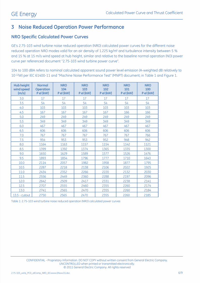
3 Noise Reduced Operation Power Performance
NRO Specific Calculated Power Curves
GEs 2.75-103 wind turbine noise reduced operation (NRO) calculated power curves for the different noise
reduced operation NRO modes valid for an air density of 1.225 kg/m3 and turbulence intensity between 5 %
and 15 % at 15 m/s wind speed at hub height, similar and relative to the baseline normal operation (NO) power
curve per referenced document 2.75-103 wind turbine power curve.
104 to 100 dBA refers to nominal calculated apparent sound power level emission (A-weighted dB relatively to
10-12W) per IEC 61400-11 and Machine Noise Performance Test (MNPT) document; in Table 1 and Figure 1.
Hub heightwind speed
[m/s]
NormalOperationP el [kW]
NRO104
P el [kW]
NRO103
P el [kW]
NRO102
P el [kW]
NRO101
P el [kW]
NRO100
P el [kW]
3.0 17 17 17 17 17 173.5 54 54 54 54 54 54
4.0 103 103 103 103 103 103
4.5 167 167 167 167 166 166
5.0 249 249 249 249 249 249
5.5 349 349 349 349 349 349
6.0 467 467 467 467 467 467
6.5 606 606 606 606 606 606
7.0 767 767 767 767 767 766
7.5 954 953 953 952 948 942
8.0 1164 1163 1157 1154 1142 1121
8.5 1399 1392 1374 1365 1335 13009.0 1650 1629 1589 1577 1526 1476
9.5 1893 1854 1796 1777 1710 1643
10.0 2114 2057 1982 1958 1877 1795
10.5 2287 2218 2138 2106 2022 1925
11.0 2434 2352 2266 2220 2132 2030
11.5 2556 2449 2360 2288 2197 2096
12.0 2642 2509 2417 2331 2238 2141
12.5 2707 2555 2460 2355 2260 2174
13.0 2741 2565 2470 2355 2260 2184
13.5 - cutout 2750 2565 2470 2355 2260 2185
Table 1: 2.75-103 wind turbine noise reduced operation (NRO) calculated power curves

7/27/2019 Appendix a _ Turbine Manufacturer Technical Specification_2.75MW
http://slidepdf.com/reader/full/appendix-a-turbine-manufacturer-technical-specification275mw 42/82
GE Energy Calculated Power Curve and Thrust Coefficient
CONFIDENTIAL - Proprietary Information. DO NOT COPY without written consent from General Electric Company.UNCONTROLLED when printed or transmitted electronically.
© 2011 General Electric Company. All rights reserved
2.75-103_xxHz_PCD_allComp_NRO_IECxxxxx.ENxxx.01.doc 7/9
NRO Power Output 2.75-103
0300600900
120015001800210024002700
3000
0 2 4 6 8 10 12 14 16
Hub height wind speed [m/s]
P o w e r [ k W ]
2.75-103 Normal Operationmax. reference L_WA = 104 dB(A)max. reference L_WA = 103 dB(A)max. reference L_WA = 102 dB(A)max. reference L_WA = 101 dB(A)max. reference L_WA = 100 dB(A)
Cut-out
Figure 1: 2.75-103 wind turbine noise reduced operation (NRO) calculated power curves
NRO 8/24 Hours Daily Cycle
Typically noise reduced operation (NRO) applications relate to 16 hours (day time) normal operations and
8 hours (night time) which is referred as NRO 8/24 hours daily cycle as presented in Table 2 and Figure 2.
Hub height
wind speed[m/s]
NormalOperation
NRO104
NRO103
NRO102
NRO101
NRO100
7 100.0% 99.0% 98.2% 97.6% 96.7% 95.8%
7.5 100.0% 98.9% 98.0% 97.4% 96.4% 95.5%
8 100.0% 98.8% 97.9% 97.2% 96.2% 95.3%
8.5 100.0% 98.7% 97.8% 97.0% 96.0% 95.1%
Table 2: 2.75-103 wind turbine NRO 8/24 cycle calculated relative annual energy production (AEP)
2.75-103 Relative Annual Energy Production for 8/24 hrs NRO mode
90%
92%
94%
96%
98%
100%
7 7,5 8 8,5
Annual mean hub height wind speed [m/s]
R e l a t i v e % A
E P
2.75-103 Baseline
max. reference L_WA= 104 dB(A)
max. reference L_WA= 103 dB(A)
max. reference L_WA= 102 dB(A)
max. reference L_WA= 101 dB(A)
max. reference L_WA= 100 dB(A)
Figure 2: 2.75-103 wind turbine NRO 8/24 cycle calculated relative annual energy production (AEP)
7/27/2019 Appendix a _ Turbine Manufacturer Technical Specification_2.75MW
http://slidepdf.com/reader/full/appendix-a-turbine-manufacturer-technical-specification275mw 43/82
GE Energy Calculated Power Curve and Thrust Coefficient
CONFIDENTIAL - Proprietary Information. DO NOT COPY without written consent from General Electric Company.UNCONTROLLED when printed or transmitted electronically.
© 2011 General Electric Company. All rights reserved
2.75-103_xxHz_PCD_allComp_NRO_IECxxxxx.ENxxx.01.doc 8/9
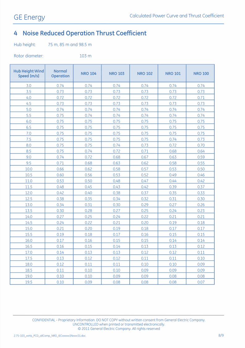
4 Noise Reduced Operation Thrust Coefficient
Hub height: 75 m, 85 m and 98.5 m
Rotor diameter: 103 m
Hub Height WindSpeed [m/s]
NormalOperation
NRO 104 NRO 103 NRO 102 NRO 101 NRO 100
3.0 0.74 0.74 0.74 0.74 0.74 0.74
3.5 0.73 0.73 0.73 0.73 0.73 0.73
4.0 0.72 0.72 0.72 0.72 0.72 0.71
4.5 0.73 0.73 0.73 0.73 0.73 0.73
5.0 0.74 0.74 0.74 0.74 0.74 0.74
5.5 0.75 0.74 0.74 0.74 0.74 0.74
6.0 0.75 0.75 0.75 0.75 0.75 0.756.5 0.75 0.75 0.75 0.75 0.75 0.75
7.0 0.75 0.75 0.75 0.75 0.75 0.75
7.5 0.75 0.75 0.75 0.75 0.74 0.73
8.0 0.75 0.75 0.74 0.73 0.72 0.70
8.5 0.75 0.74 0.72 0.71 0.68 0.64
9.0 0.74 0.72 0.68 0.67 0.63 0.59
9.5 0.71 0.68 0.63 0.62 0.58 0.55
10.0 0.66 0.62 0.58 0.57 0.53 0.50
10.5 0.60 0.56 0.53 0.52 0.49 0.46
11.0 0.53 0.50 0.48 0.47 0.44 0.4211.5 0.48 0.45 0.43 0.42 0.39 0.37
12.0 0.42 0.40 0.38 0.37 0.35 0.33
12.5 0.38 0.35 0.34 0.32 0.31 0.30
13.0 0.34 0.31 0.30 0.29 0.27 0.26
13.5 0.30 0.28 0.27 0.25 0.24 0.23
14.0 0.27 0.25 0.24 0.22 0.21 0.21
14.5 0.24 0.22 0.21 0.20 0.19 0.18
15.0 0.21 0.20 0.19 0.18 0.17 0.17
15.5 0.19 0.18 0.17 0.16 0.15 0.15
16.0 0.17 0.16 0.15 0.15 0.14 0.14
16.5 0.16 0.15 0.14 0.13 0.13 0.12
17.0 0.14 0.13 0.13 0.12 0.12 0.11
17.5 0.13 0.12 0.12 0.11 0.11 0.10
18.0 0.12 0.11 0.11 0.10 0.10 0.09
18.5 0.11 0.10 0.10 0.09 0.09 0.09
19.0 0.10 0.10 0.09 0.09 0.08 0.08
19.5 0.10 0.09 0.08 0.08 0.08 0.07
7/27/2019 Appendix a _ Turbine Manufacturer Technical Specification_2.75MW
http://slidepdf.com/reader/full/appendix-a-turbine-manufacturer-technical-specification275mw 44/82
GE Energy Calculated Power Curve and Thrust Coefficient
CONFIDENTIAL - Proprietary Information. DO NOT COPY without written consent from General Electric Company.UNCONTROLLED when printed or transmitted electronically.
© 2011 General Electric Company. All rights reserved
2.75-103_xxHz_PCD_allComp_NRO_IECxxxxx.ENxxx.01.doc 9/9
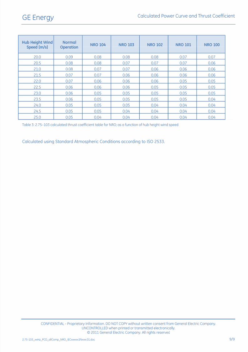
Hub Height WindSpeed [m/s]
NormalOperation
NRO 104 NRO 103 NRO 102 NRO 101 NRO 100
20.0 0.09 0.08 0.08 0.08 0.07 0.07
20.5 0.08 0.08 0.07 0.07 0.07 0.06
21.0 0.08 0.07 0.07 0.06 0.06 0.06
21.5 0.07 0.07 0.06 0.06 0.06 0.06
22.0 0.07 0.06 0.06 0.06 0.05 0.05
22.5 0.06 0.06 0.06 0.05 0.05 0.05
23.0 0.06 0.05 0.05 0.05 0.05 0.05
23.5 0.06 0.05 0.05 0.05 0.05 0.04
24.0 0.05 0.05 0.05 0.04 0.04 0.04
24.5 0.05 0.05 0.04 0.04 0.04 0.04
25.0 0.05 0.04 0.04 0.04 0.04 0.04
Table 3: 2.75103 calculated thrust coefficient table for NRO; as a function of hub height wind speed
Calculated using Standard Atmospheric Conditions according to ISO 2533.
7/27/2019 Appendix a _ Turbine Manufacturer Technical Specification_2.75MW
http://slidepdf.com/reader/full/appendix-a-turbine-manufacturer-technical-specification275mw 45/82
GE Energy
Technical Documentation
Wind Turbine Generator Systems2.5-2.75 Series
Specification
Site Roads and Crane Pad
imagination at work© 2010 General Electric Company. All rights reserved.
7/27/2019 Appendix a _ Turbine Manufacturer Technical Specification_2.75MW
http://slidepdf.com/reader/full/appendix-a-turbine-manufacturer-technical-specification275mw 46/82
GE Energy
Gepower.com
Visit us atwww.gewindenergy.com
All technical data is subject to change in line with ongoing technical development!
Copyright and patent rights
This document is to be treated confidentially. It may only be made accessible to authorized persons. It may
only be made available to third parties with the expressed written consent of General Electric Company.
All documents are copyrighted within the meaning of the Copyright Act. The transmission and reproduction of
the documents, also in extracts, as well as the exploitation and communication of the contents are not allowed
without express written consent. Contraventions are liable to prosecution and compensation for damage. We
reserve all rights for the exercise of commercial patent rights.
© 2010 General Electric Company. All rights reserved.
GE and are trademarks and service marks of General Electric Company.
Other company or product names mentioned in this document may be trademarks or registered trademarks of
their respective companies.
imagination at work2.5-2.75_Series_xxHz_SPC_roadcrane_descriptionx.ENxxx.00.doc.

7/27/2019 Appendix a _ Turbine Manufacturer Technical Specification_2.75MW
http://slidepdf.com/reader/full/appendix-a-turbine-manufacturer-technical-specification275mw 47/82
GE Energy Specification
CONFIDENTIAL - Proprietary Information. DO NOT COPY without written consent from General Electric Company.UNCONTROLLED when printed or transmitted electronically.
© 2010 General Electric Company. All rights reserved
2.5-2.75_Series_xxHz_SPC_roadcrane_descriptionx.ENxxx.00.doc x
Table of Contents
1 Requirements..............................................................................................................................................................................................................52 Transport Vehicles (examples)...........................................................................................................................................................................52.1 Vehicle Weights...............................................................................................................................................................................................6
3 Access and Site Roads/Entrances...................................................................................................................................................................73.1 Road Curves and Entrance Curves ......................................................................................................................................................73.2 Turning Curves.................................................................................................................................................................................................73.3 Gradient............................................................................................................................................................................................................143.4 Road Camber ................................................................................................................................................................................................143.5 Clearance, Height and Width...............................................................................................................................................................143.6 New Site Roads ............................................................................................................................................................................................153.7 Upgrading of Existing Roads ................................................................................................................................................................16
Plate Load Bearing Test of the Construction Layer ............................................................................................................................16
3.8 Ground Clearance of Transport Vehicles.......................................................................................................................................174 Crane Pad................................................................................................................................................................................................................... 185 Parking Area / Turning Area............................................................................................................................................................................. 23
5.1 Parking Area...................................................................................................................................................................................................235.2 Turning Area for Unloaded Vehicles.................................................................................................................................................23
6 Soil Backfilling/Foundation Area ................................................................................................................................................................... 237 Crawler Crane Movements on Site ..............................................................................................................................................................248 Site Compound........................................................................................................................................................................................................249 Storage of the Plant Components................................................................................................................................................................2510 Crane assembling area.................................................................................................................................................................................27
10.1 Crawler Crane with Lattice Main Boom.......................................................................................................................................... 27
10.2 Telescopic Crane with Lattice Jib.......................................................................................................................................................2710.3 Wheeled Crane with Lattice Main Boom.......................................................................................................................................28

7/27/2019 Appendix a _ Turbine Manufacturer Technical Specification_2.75MW
http://slidepdf.com/reader/full/appendix-a-turbine-manufacturer-technical-specification275mw 48/82

7/27/2019 Appendix a _ Turbine Manufacturer Technical Specification_2.75MW
http://slidepdf.com/reader/full/appendix-a-turbine-manufacturer-technical-specification275mw 49/82
GE Energy Specification
1 Requirements
This specification describes the major dimensions and weights of the vehicles required for transportation of the
main components of the GE 2.5-2.75 Series Wind Turbine Generator System (WTGS). Furthermore, the
minimum requirements (based on normal ground conditions) for access roads and crane pads described
herein must be met to ensure the proper installation of the WTGS.
Please note that additional measures may be necessary in theevent of deviant conditions!
2 Transport Vehicles (examples)
• 15 heavy-duty trucks for erecting and dismantling the crane
• 13 heavy-duty trucks with plant components consisting of:
o 1 for tower base ring
o 2 for PPM system
o 4-5 for tower sections
o 1 for nacelle
o 1 for hubo 3 for rotor blades
Figure 1: Example of transport vehicle for the nacelle
CONFIDENTIAL - Proprietary Information. DO NOT COPY without written consent from General Electric Company.UNCONTROLLED when printed or transmitted electronically.
© 2010 General Electric Company. All rights reserved
2.5-2.75_Series_xxHz_SPC_roadcrane_descriptionx.ENxxx.00.doc 5/28

7/27/2019 Appendix a _ Turbine Manufacturer Technical Specification_2.75MW
http://slidepdf.com/reader/full/appendix-a-turbine-manufacturer-technical-specification275mw 50/82
GE Energy Specification
Figure 2: Example of transport vehicle for the tower sections
Figure 3: Example of transport vehicle for the blades
The equipment and dimensions may vary due to availability. The maximum vehicle length is 56 m when loaded
with the rotor blade. The vehicle length is measured from the front of the transporter to the end of the load.
2.1 Vehicle Weights
• Maximum. axle load 12-16 t, onsite for cranes and transport vehicles
• Maximum individual weight approximately 140 t
CONFIDENTIAL - Proprietary Information. DO NOT COPY without written consent from General Electric Company.UNCONTROLLED when printed or transmitted electronically.
© 2010 General Electric Company. All rights reserved
6/28 2.5-2.75_Series_xxHz_SPC_roadcrane_descriptionx.ENxxx.00.doc
7/27/2019 Appendix a _ Turbine Manufacturer Technical Specification_2.75MW
http://slidepdf.com/reader/full/appendix-a-turbine-manufacturer-technical-specification275mw 51/82
GE Energy Specification
CONFIDENTIAL - Proprietary Information. DO NOT COPY without written consent from General Electric Company.
3 Access and Site Roads/Entrances
3.1 Road Curves and Entrance Curves
The road curves and entrance curves must be constructed to the dimensions shown in the figures below. The
dimensions are based on the rotor blade transport vehicle due to the fact that this vehicle requires the most
compacted area to pass the curves.
All stored and excavated topsoil or any obstacles in the areas next to or near the road or entrance curves must
be removed or leveled before turbine delivery can begin. All open cable trenches that run along the roads or
crane pads must be refilled before any turbine delivery and construction can begin.
GE Energy will not take responsibility for any damage to the roads that has been caused by the transport
vehicles or cranes when the access roads or site roads have not been properly constructed. This will apply also
for damage caused to vehicles due to unsuitably constructed roads, waiting time, or recovery costs.
3.2 Turning Curves
The curve radii for transportation vehicles can be obtained from the following drawings:
• Figure 4: Truck with rear axle steering, outside radius 12.5m / turning angle 90° on page 8
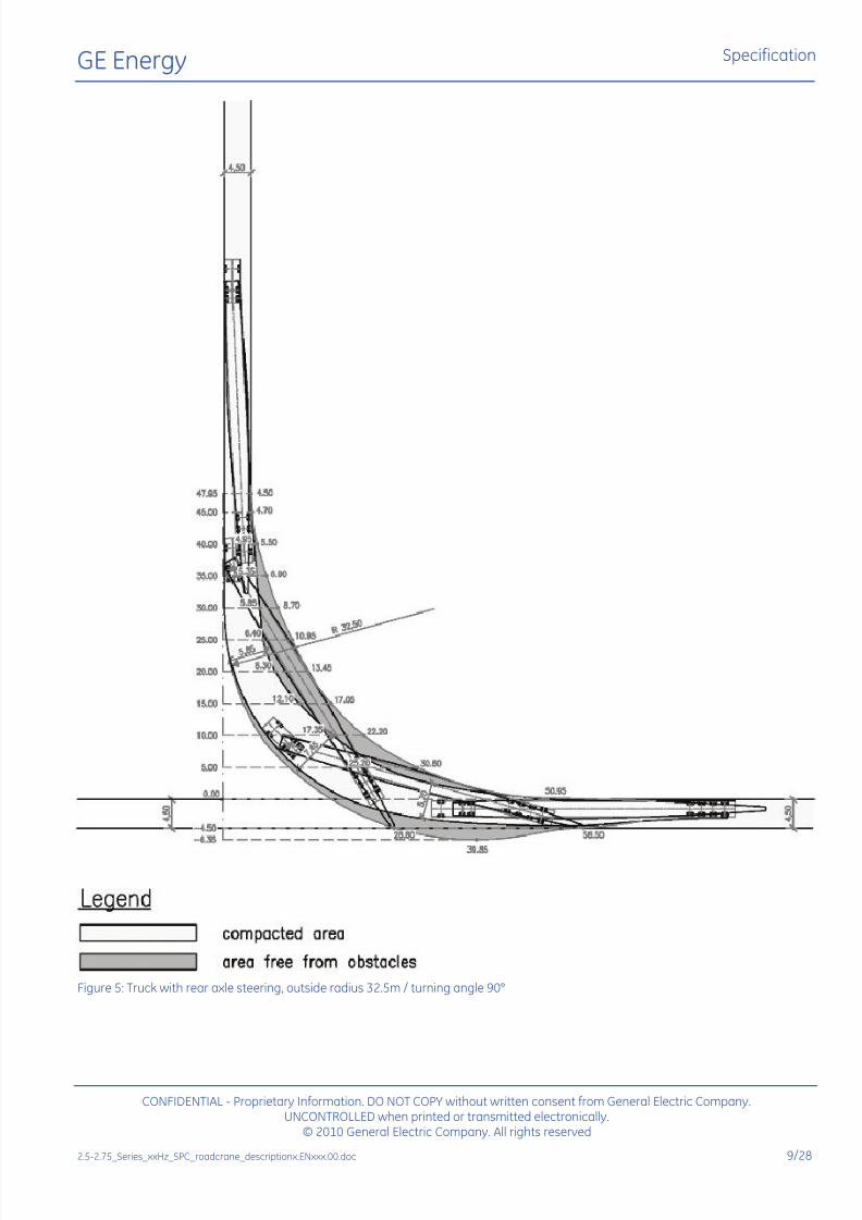
• Figure 5: Truck with rear axle steering, outside radius 32.5m / turning angle 90° on page 9
UNCONTROLLED when printed or transmitted electronically.© 2010 General Electric Company. All rights reserved
2.5-2.75_Series_xxHz_SPC_roadcrane_descriptionx.ENxxx.00.doc 7/28
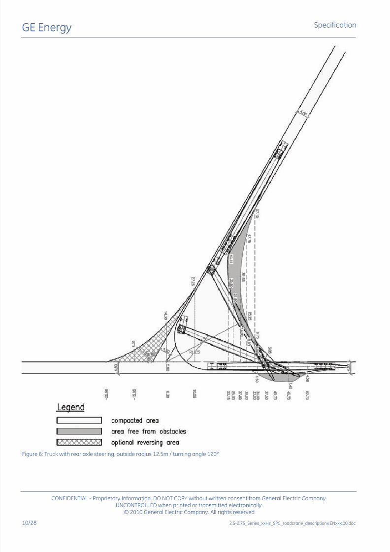
• Figure 6: Truck with rear axle steering, outside radius 12.5m / turning angle 120° on page 10
• Figure 7: Truck with rear axle steering, outside radius 32.5m / turning angle 120° on page 11
• Figure 8: Truck with rear axle steering, outside radius 32.5m / turning angle 150° on page 12• Figure 9: Truck with rear axle steering, outside radius 32.5m / turning angle 180° on page 13
Please note that additional measures may be necessary in theevent of deviant conditions or equipment used!

7/27/2019 Appendix a _ Turbine Manufacturer Technical Specification_2.75MW
http://slidepdf.com/reader/full/appendix-a-turbine-manufacturer-technical-specification275mw 52/82
GE Energy Specification
Figure 4: Truck with rear axle steering, outside radius 12.5m / turning angle 90°
CONFIDENTIAL - Proprietary Information. DO NOT COPY without written consent from General Electric Company.UNCONTROLLED when printed or transmitted electronically.
© 2010 General Electric Company. All rights reserved
8/28 2.5-2.75_Series_xxHz_SPC_roadcrane_descriptionx.ENxxx.00.doc
7/27/2019 Appendix a _ Turbine Manufacturer Technical Specification_2.75MW
http://slidepdf.com/reader/full/appendix-a-turbine-manufacturer-technical-specification275mw 53/82
GE Energy Specification
Figure 5: Truck with rear axle steering, outside radius 32.5m / turning angle 90°
CONFIDENTIAL - Proprietary Information. DO NOT COPY without written consent from General Electric Company.UNCONTROLLED when printed or transmitted electronically.
© 2010 General Electric Company. All rights reserved
2.5-2.75_Series_xxHz_SPC_roadcrane_descriptionx.ENxxx.00.doc 9/28
7/27/2019 Appendix a _ Turbine Manufacturer Technical Specification_2.75MW
http://slidepdf.com/reader/full/appendix-a-turbine-manufacturer-technical-specification275mw 54/82
GE Energy Specification
Figure 6: Truck with rear axle steering, outside radius 12.5m / turning angle 120°
CONFIDENTIAL - Proprietary Information. DO NOT COPY without written consent from General Electric Company.UNCONTROLLED when printed or transmitted electronically.
© 2010 General Electric Company. All rights reserved
10/28 2.5-2.75_Series_xxHz_SPC_roadcrane_descriptionx.ENxxx.00.doc

7/27/2019 Appendix a _ Turbine Manufacturer Technical Specification_2.75MW
http://slidepdf.com/reader/full/appendix-a-turbine-manufacturer-technical-specification275mw 55/82
GE Energy Specification
Figure 7: Truck with rear axle steering, outside radius 32.5m / turning angle 120°
CONFIDENTIAL - Proprietary Information. DO NOT COPY without written consent from General Electric Company.UNCONTROLLED when printed or transmitted electronically.
© 2010 General Electric Company. All rights reserved
2.5-2.75_Series_xxHz_SPC_roadcrane_descriptionx.ENxxx.00.doc 11/28

7/27/2019 Appendix a _ Turbine Manufacturer Technical Specification_2.75MW
http://slidepdf.com/reader/full/appendix-a-turbine-manufacturer-technical-specification275mw 56/82
GE Energy Specification
Figure 8: Truck with rear axle steering, outside radius 32.5m / turning angle 150°
CONFIDENTIAL - Proprietary Information. DO NOT COPY without written consent from General Electric Company.UNCONTROLLED when printed or transmitted electronically.
© 2010 General Electric Company. All rights reserved
12/28 2.5-2.75_Series_xxHz_SPC_roadcrane_descriptionx.ENxxx.00.doc

7/27/2019 Appendix a _ Turbine Manufacturer Technical Specification_2.75MW
http://slidepdf.com/reader/full/appendix-a-turbine-manufacturer-technical-specification275mw 57/82
GE Energy Specification
Figure 9: Truck with rear axle steering, outside radius 32.5m / turning angle 180°
CONFIDENTIAL - Proprietary Information. DO NOT COPY without written consent from General Electric Company.UNCONTROLLED when printed or transmitted electronically.
© 2010 General Electric Company. All rights reserved
2.5-2.75_Series_xxHz_SPC_roadcrane_descriptionx.ENxxx.00.doc 13/28

7/27/2019 Appendix a _ Turbine Manufacturer Technical Specification_2.75MW
http://slidepdf.com/reader/full/appendix-a-turbine-manufacturer-technical-specification275mw 58/82
GE Energy Specification
CONFIDENTIAL - Proprietary Information. DO NOT COPY without written consent from General Electric Company.
3.3 Gradient
In general the transport vehicles will be able to access gradients up to 6 % on straight roads without narrow
bends and under good weather and road surface conditions. It is possible to transport the turbine components
on gradients over 6 %. In those cases there will be a necessity for one or more towing/pushing vehicles to be
supplied.
If during project planning it is seen to be necessary that a towing vehicle is required for gradients over 6 %,
GE Energy and the customer will decide on the type of towing/pushing vehicles and the suitable towing
procedure with regard to the respective situation. All costs for ordering, delivery and use of the towing/
pushing vehicles are to be paid by the customer.
If during project planning it is seen to be necessary that a towing vehicle is required for gradients under 6 % it
is to be supplied by the customer at short notice. Reasons for this may be, but are not limited to:
• bad weather conditions
• poorly constructed roads etc.
All costs resulting from the need for a towing/pushing vehicle during the project phase and those costs
resulting to waiting time for GE Energy and its crane/transport vehicles will be passed on to the customer.
3.4 Road Camber
Access and site roads should have a maximum camber of 2 % for proper drainage.
3.5 Clearance, Height and Width
The customer has to ensure that on all access and site roads any overhanging tree branches, powerlines and
telephone cables are removed to avoid damage to turbine components.
Minimum height = 6.0 m, minimum width = 5.0 m according to Figure 10.
The equipment may vary due toavailability or transport strategy.
Figure 10: Clearance, onsite tower transport as example
UNCONTROLLED when printed or transmitted electronically.© 2010 General Electric Company. All rights reserved
14/28 2.5-2.75_Series_xxHz_SPC_roadcrane_descriptionx.ENxxx.00.doc
7/27/2019 Appendix a _ Turbine Manufacturer Technical Specification_2.75MW
http://slidepdf.com/reader/full/appendix-a-turbine-manufacturer-technical-specification275mw 59/82
GE Energy Specification
3.6 New Site Roads
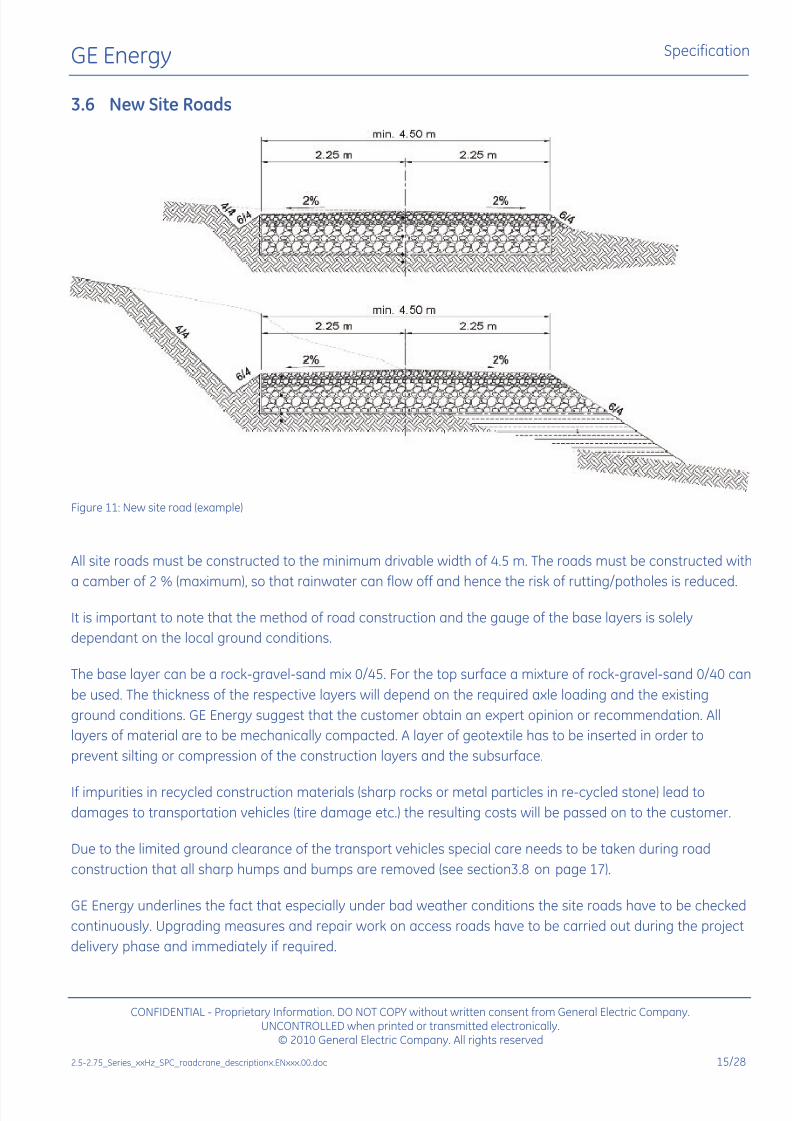
Figure 11: New site road (example)
All site roads must be constructed to the minimum drivable width of 4.5 m. The roads must be constructed with
a camber of 2 % (maximum), so that rainwater can flow off and hence the risk of rutting/potholes is reduced.
It is important to note that the method of road construction and the gauge of the base layers is solely
dependant on the local ground conditions.
The base layer can be a rock-gravel-sand mix 0/45. For the top surface a mixture of rock-gravel-sand 0/40 can
be used. The thickness of the respective layers will depend on the required axle loading and the existing
ground conditions. GE Energy suggest that the customer obtain an expert opinion or recommendation. All
layers of material are to be mechanically compacted. A layer of geotextile has to be inserted in order to
prevent silting or compression of the construction layers and the subsurface.
If impurities in recycled construction materials (sharp rocks or metal particles in re-cycled stone) lead to
damages to transportation vehicles (tire damage etc.) the resulting costs will be passed on to the customer.
Due to the limited ground clearance of the transport vehicles special care needs to be taken during road
construction that all sharp humps and bumps are removed (see section 3.8 on page 17).
GE Energy underlines the fact that especially under bad weather conditions the site roads have to be checked
continuously. Upgrading measures and repair work on access roads have to be carried out during the project
delivery phase and immediately if required.
CONFIDENTIAL - Proprietary Information. DO NOT COPY without written consent from General Electric Company.UNCONTROLLED when printed or transmitted electronically.
© 2010 General Electric Company. All rights reserved
2.5-2.75_Series_xxHz_SPC_roadcrane_descriptionx.ENxxx.00.doc 15/28
7/27/2019 Appendix a _ Turbine Manufacturer Technical Specification_2.75MW
http://slidepdf.com/reader/full/appendix-a-turbine-manufacturer-technical-specification275mw 60/82
GE Energy Specification
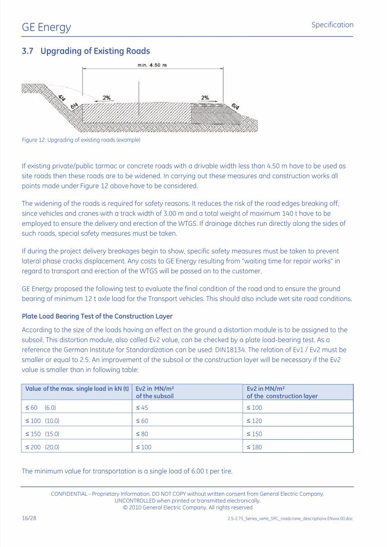
3.7 Upgrading of Existing Roads
Figure 12: Upgrading of existing roads (example)
Figure 12
If existing private/public tarmac or concrete roads with a drivable width less than 4.50 m have to be used as
site roads then these roads are to be widened. In carrying out these measures and construction works all
points made under above have to be considered.
The widening of the roads is required for safety reasons. It reduces the risk of the road edges breaking off,
since vehicles and cranes with a track width of 3.00 m and a total weight of maximum 140 t have to be
employed to ensure the delivery and erection of the WTGS. If drainage ditches run directly along the sides of
such roads, special safety measures must be taken.
If during the project delivery breakages begin to show, specific safety measures must be taken to prevent
lateral phase cracks displacement. Any costs to GE Energy resulting from waiting time for repair works in
regard to transport and erection of the WTGS will be passed on to the customer.
GE Energy proposed the following test to evaluate the final condition of the road and to ensure the groundbearing of minimum 12 t axle load for the Transport vehicles. This should also include wet site road conditions.
Plate Load Bearing Test of the Construction Layer
According to the size of the loads having an effect on the ground a distortion module is to be assigned to the
subsoil. This distortion module, also called Ev2 value, can be checked by a plate load-bearing test. As a
reference the German Institute for Standardization can be used: DIN18134. The relation of Ev1 / Ev2 must be
smaller or equal to 2.5. An improvement of the subsoil or the construction layer will be necessary if the Ev2
value is smaller than in following table:
Value of the max. single load in kN (t) Ev2 in MN/m²of the subsoil
Ev2 in MN/m²of the construction layer
≤ 60 (6.0) ≤ 45 ≤ 100
≤ 100 (10.0) ≤ 60 ≤ 120
≤ 150 (15.0) ≤ 80 ≤ 150
≤ 200 (20.0) ≤ 100 ≤ 180
The minimum value for transportation is a single load of 6.00 t per tire.
CONFIDENTIAL - Proprietary Information. DO NOT COPY without written consent from General Electric Company.UNCONTROLLED when printed or transmitted electronically.
© 2010 General Electric Company. All rights reserved
16/28 2.5-2.75_Series_xxHz_SPC_roadcrane_descriptionx.ENxxx.00.doc

7/27/2019 Appendix a _ Turbine Manufacturer Technical Specification_2.75MW
http://slidepdf.com/reader/full/appendix-a-turbine-manufacturer-technical-specification275mw 61/82
GE Energy Specification
3.8 Ground Clearance of Transport Vehicles
When constructing the site roads care must be taken to try to keep the gradients of any hills to a minimum.
The requirements are explained in Figure 13.
Extra care must be taken to make sure that any sharp road humps along the site roads and access routes areleveled out to reduce the risk of the vehicles grounding and damaging the components and their vehicles.
The overall height of the vehicles employed for the transportation of the tower sections has to be as low as
possible. The ground clearance for such vehicles is 20 cm. Therefore, it has to be considered already at the
planning stage that depressions and ridges in the access roads are filled in and leveled.
Figure 13: Ground clearance (example)
CONFIDENTIAL - Proprietary Information. DO NOT COPY without written consent from General Electric Company.UNCONTROLLED when printed or transmitted electronically.
© 2010 General Electric Company. All rights reserved
2.5-2.75_Series_xxHz_SPC_roadcrane_descriptionx.ENxxx.00.doc 17/28

7/27/2019 Appendix a _ Turbine Manufacturer Technical Specification_2.75MW
http://slidepdf.com/reader/full/appendix-a-turbine-manufacturer-technical-specification275mw 62/82
GE Energy Specification
4 Crane Pad
The crane pads must be constructed as shown in Figure 14 to Figure 18. Both wheel-mounted and crawler-
mounted cranes can be used. For the mobilization of those cranes the axle weight will be 12 t.
Figure 14: Cross section crane pad
All crane pads must be at-grade with a maximum slope of 1 % of the total length and width of the entire area.
Soil and obstacles may not be deposited around the crane pad or for a distance of 130 m along the site road.
This area is required for the assembly of the crane boom.
A 2 m wide gravel path must be constructed from the crane pad/road to and around the turbine to prevent
soiling of the plant.
The areas with a width of 10 m on the right and left of the crane pads are used for assembly of the rotor and
storage of the plant components (see Figure 20 and Figure 21). Permission for the use of these areas will have
to be obtained by the customer from the landowner and submitted to GE Energy before the erection phasestarts.
Any variations to the above are only permissible with theapproval of a representative of GE Energy.
CONFIDENTIAL - Proprietary Information. DO NOT COPY without written consent from General Electric Company.UNCONTROLLED when printed or transmitted electronically.
© 2010 General Electric Company. All rights reserved
18/28 2.5-2.75_Series_xxHz_SPC_roadcrane_descriptionx.ENxxx.00.doc
7/27/2019 Appendix a _ Turbine Manufacturer Technical Specification_2.75MW
http://slidepdf.com/reader/full/appendix-a-turbine-manufacturer-technical-specification275mw 63/82
GE Energy Specification
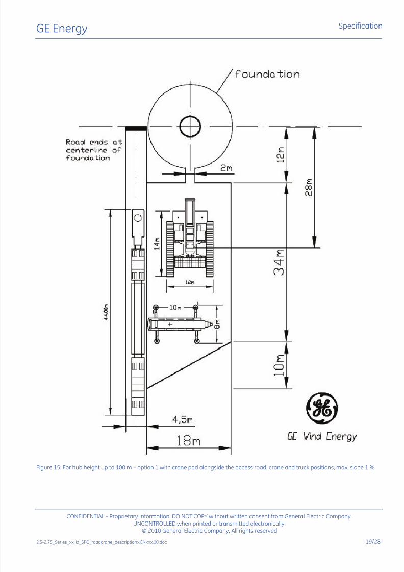
Figure 15: For hub height up to 100 m option 1 with crane pad alongside the access road, crane and truck positions, max. slope 1 %
CONFIDENTIAL - Proprietary Information. DO NOT COPY without written consent from General Electric Company.UNCONTROLLED when printed or transmitted electronically.
© 2010 General Electric Company. All rights reserved
2.5-2.75_Series_xxHz_SPC_roadcrane_descriptionx.ENxxx.00.doc 19/28
7/27/2019 Appendix a _ Turbine Manufacturer Technical Specification_2.75MW
http://slidepdf.com/reader/full/appendix-a-turbine-manufacturer-technical-specification275mw 64/82
GE Energy Specification
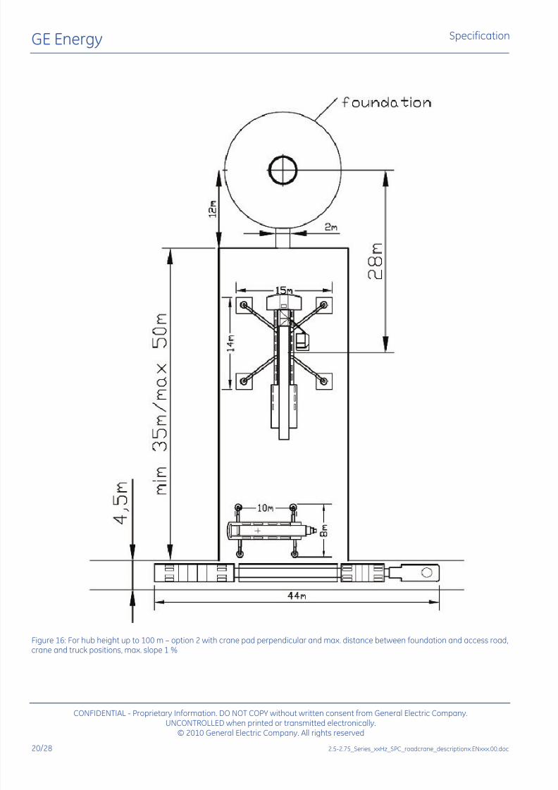
Figure 16: For hub height up to 100 m option 2 with crane pad perpendicular and max. distance between foundation and access road,crane and truck positions, max. slope 1 %
CONFIDENTIAL - Proprietary Information. DO NOT COPY without written consent from General Electric Company.UNCONTROLLED when printed or transmitted electronically.
© 2010 General Electric Company. All rights reserved
20/28 2.5-2.75_Series_xxHz_SPC_roadcrane_descriptionx.ENxxx.00.doc

7/27/2019 Appendix a _ Turbine Manufacturer Technical Specification_2.75MW
http://slidepdf.com/reader/full/appendix-a-turbine-manufacturer-technical-specification275mw 65/82
GE Energy Specification
Figure 17: For hub height up to 140 m option 1 with crane pad alongside the access road, crane and truck positions, max. slope 1 %
CONFIDENTIAL - Proprietary Information. DO NOT COPY without written consent from General Electric Company.UNCONTROLLED when printed or transmitted electronically.
© 2010 General Electric Company. All rights reserved
2.5-2.75_Series_xxHz_SPC_roadcrane_descriptionx.ENxxx.00.doc 21/28

7/27/2019 Appendix a _ Turbine Manufacturer Technical Specification_2.75MW
http://slidepdf.com/reader/full/appendix-a-turbine-manufacturer-technical-specification275mw 66/82
GE Energy Specification
Figure 18: For hub height up to 140 m option 2 with crane pad perpendicular and max. distance between foundation and access road,crane and truck positions, max. slope 1 %
CONFIDENTIAL - Proprietary Information. DO NOT COPY without written consent from General Electric Company.UNCONTROLLED when printed or transmitted electronically.
© 2010 General Electric Company. All rights reserved
22/28 2.5-2.75_Series_xxHz_SPC_roadcrane_descriptionx.ENxxx.00.doc
7/27/2019 Appendix a _ Turbine Manufacturer Technical Specification_2.75MW
http://slidepdf.com/reader/full/appendix-a-turbine-manufacturer-technical-specification275mw 67/82
GE Energy Specification
CONFIDENTIAL - Proprietary Information. DO NOT COPY without written consent from General Electric Company.UNCONTROLLED when printed or transmitted electronically.
© 2010 General Electric Company. All rights reserved
2.5-2.75_Series_xxHz_SPC_roadcrane_descriptionx.ENxxx.00.doc 23/28
5 Parking Area / Turning Area
5.1 Parking Area
Parking areas for at least four component transport vehicles with a length of 50 m and a width of 5 m have to
be made available within the windfarm area. If the vehicles will be required to park on public roads or
highways then the required permits, signs and lighting will have to be obtained from the appropriate
authorities by the customer. These permits will be required before transportation activities start.
5.2 Turning Area for Unloaded Vehicles
GE Energy suggests to the customer that at certain areas within the windfarm, turning-areas for the vehicles
shall be included in their planning. These areas will firstly allow the vehicles to keep to the designated site
roads and reduce the amount of time that they will need for reversing out of the windfarm. Secondly it will
reduce the risk of vehicles getting stuck or causing damage.
6 Soil Backfilling/Foundation Area
During the installation of the WTGS an area of 10 m around the foundation (∅ 9 m) is needed for the usage of
an all-terrain forklift for the installation of turbine equipment outside the tower. This means that if soil
backfilling is required due to the foundation design the finish of this work scope has to be done after the
turbine is erected.
A gravel path of 2 m width must be constructed from the crane pad/road to and around the turbine to prevent
soiling of the plant.

7/27/2019 Appendix a _ Turbine Manufacturer Technical Specification_2.75MW
http://slidepdf.com/reader/full/appendix-a-turbine-manufacturer-technical-specification275mw 68/82
GE Energy Specification
CONFIDENTIAL - Proprietary Information. DO NOT COPY without written consent from General Electric Company.
7 Crawler Crane Movements on Site
If it is planned to use a crawler crane moving on site directly between the turbine unit locations the following
points needs to be considered.
• Permits/permissions (from landowner) to move with the crawler crane directly over the landbetween the several turbines locations shall be obtained by the customer
• Crane pad level of 1 % gradient maximum in all directions
• Crane pads need to be accessible for the crawler crane
• Lateral inclination during movement of the crane: Maximum 2 % gradient
• Free (drive-through) area needed to move between the several turbines locations is 12 m
• There are two options to move the crawler crane:
o Option 1: One track in the middle of the site road (4.5 m wide), and the other track in the area
beside the road (10 m wide)o Option 2: Use the free land to move the crane directly between the turbine locations
• Max. slope in moving direction is approx. 10 %
• Free area of 10 m x ? m (length of the crane boom) for the assembly of the crane boom at the
first turbine and disassembly at the last turbine
• Ground pressure under the tracks as,
for example, for a Liebherr LR 1600 is
approx. 220 KN/m². Ground pressure
can vary due to different crane type
Please note that additional measuresmay be necessary in the event of deviant conditions!
Figure 19: Ground pressure under the tracks
8 Site Compound
GE Energy will require a hardstanding to be constructed by the customer for use as a site compound. This area
needs to be leveled and constructed with clean fine gravel stone. GE Energy will place site containers, toiletsand equipment in this area and will therefore require electrical connections and waste water collection. The
required dimensions of this area are minimum 20 m x 20 m for a windfarm size up to 20 units. GE Energy will
give details as to its position within the windfarm in cooperation with the customer at a later date.
Any variations to the GE Energy specification may only be carriedout after they have been discussed and approved by GE Energy.
UNCONTROLLED when printed or transmitted electronically.© 2010 General Electric Company. All rights reserved
24/28 2.5-2.75_Series_xxHz_SPC_roadcrane_descriptionx.ENxxx.00.doc
7/27/2019 Appendix a _ Turbine Manufacturer Technical Specification_2.75MW
http://slidepdf.com/reader/full/appendix-a-turbine-manufacturer-technical-specification275mw 69/82
GE Energy Specification
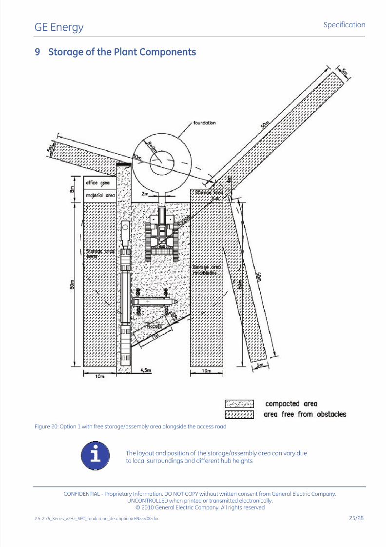
9 Storage of the Plant Components
Figure 20: Option 1 with free storage/assembly area alongside the access road
The layout and position of the storage/assembly area can vary dueto local surroundings and different hub heights
CONFIDENTIAL - Proprietary Information. DO NOT COPY without written consent from General Electric Company.UNCONTROLLED when printed or transmitted electronically.
© 2010 General Electric Company. All rights reserved
2.5-2.75_Series_xxHz_SPC_roadcrane_descriptionx.ENxxx.00.doc 25/28

7/27/2019 Appendix a _ Turbine Manufacturer Technical Specification_2.75MW
http://slidepdf.com/reader/full/appendix-a-turbine-manufacturer-technical-specification275mw 70/82
GE Energy Specification
Figure 21: Option 2, perpendicular, with maximum distance between foundation and access road
The layout and position of the storage/assembly area can vary dueto local surroundings and different hub heights
CONFIDENTIAL - Proprietary Information. DO NOT COPY without written consent from General Electric Company.UNCONTROLLED when printed or transmitted electronically.
© 2010 General Electric Company. All rights reserved
26/28 2.5-2.75_Series_xxHz_SPC_roadcrane_descriptionx.ENxxx.00.doc

7/27/2019 Appendix a _ Turbine Manufacturer Technical Specification_2.75MW
http://slidepdf.com/reader/full/appendix-a-turbine-manufacturer-technical-specification275mw 71/82
GE Energy Specification
10 Crane assembling area
For the assembly of the main boom/jib of the main crane a free area must be provided. This area needs to be
accessible for the assisting crane which will always be required. The assisting crane will also require a plain
area beside the site road, or along the direction chosen for the assembly of the main boom/jib.
Shown below are some examples of the types of cranes that can be used for the installation of the turbines as
well as details of the areas required for the assembly of the main boom/jib and assisting crane. The
requirements listed below are based on a stable terrain with a specified maximum gradient/decline for the
assembly of the main boom/jib. If the conditions below cannot be achieved, then project specific options will
need to be discussed and implemented.
10.1 Crawler Crane with Lattice Main Boom
• Required area for assembly 130 m x 10 m
• Maximum gradient/decline for main boom/jib assembly 8 % uphill
• Clear and flat areas for assisting crane 10 m x 10 m
Figure 22: Crawler crane with lattice main boom
10.2 Telescopic Crane with Lattice Jib
• Required area for assembly 90 m x 10 m
• Maximum gradient/decline for main boom/jib assembly 8 % uphill
• Clear and flat areas for assisting crane 10 m x 10 m
Figure 23: Telescopic crane with lattice jib
CONFIDENTIAL - Proprietary Information. DO NOT COPY without written consent from General Electric Company.UNCONTROLLED when printed or transmitted electronically.
© 2010 General Electric Company. All rights reserved
2.5-2.75_Series_xxHz_SPC_roadcrane_descriptionx.ENxxx.00.doc 27/28

7/27/2019 Appendix a _ Turbine Manufacturer Technical Specification_2.75MW
http://slidepdf.com/reader/full/appendix-a-turbine-manufacturer-technical-specification275mw 72/82
GE Energy Specification
10.3 Wheeled Crane with Lattice Main Boom
• Required area for assembly 130 m x 10 m
• Maximum gradient/decline for main boom/jib assembly 8 % uphill
• Clear and flat areas for assisting crane 10 m x 10 m
Figure 24: Wheeled crane with lattice main boom
The required area for assembly of the crane boom can vary due todifferent hub heights, equipment used and to local surroundings.These drawing are only to be used as an example.
Crane boom assembly downhill is complicated and may not bepossible. If the assembly of the boom cannot be carried out on aplain or uphill area please contact project management for furtherinstructions.
CONFIDENTIAL - Proprietary Information. DO NOT COPY without written consent from General Electric Company.UNCONTROLLED when printed or transmitted electronically.
© 2010 General Electric Company. All rights reserved
28/28 2.5-2.75_Series_xxHz_SPC_roadcrane_descriptionx.ENxxx.00.doc
7/27/2019 Appendix a _ Turbine Manufacturer Technical Specification_2.75MW
http://slidepdf.com/reader/full/appendix-a-turbine-manufacturer-technical-specification275mw 73/82
7/27/2019 Appendix a _ Turbine Manufacturer Technical Specification_2.75MW
http://slidepdf.com/reader/full/appendix-a-turbine-manufacturer-technical-specification275mw 74/82

7/27/2019 Appendix a _ Turbine Manufacturer Technical Specification_2.75MW
http://slidepdf.com/reader/full/appendix-a-turbine-manufacturer-technical-specification275mw 75/82

7/27/2019 Appendix a _ Turbine Manufacturer Technical Specification_2.75MW
http://slidepdf.com/reader/full/appendix-a-turbine-manufacturer-technical-specification275mw 76/82
7/27/2019 Appendix a _ Turbine Manufacturer Technical Specification_2.75MW
http://slidepdf.com/reader/full/appendix-a-turbine-manufacturer-technical-specification275mw 77/82

7/27/2019 Appendix a _ Turbine Manufacturer Technical Specification_2.75MW
http://slidepdf.com/reader/full/appendix-a-turbine-manufacturer-technical-specification275mw 78/82

7/27/2019 Appendix a _ Turbine Manufacturer Technical Specification_2.75MW
http://slidepdf.com/reader/full/appendix-a-turbine-manufacturer-technical-specification275mw 79/82
7/27/2019 Appendix a _ Turbine Manufacturer Technical Specification_2.75MW
http://slidepdf.com/reader/full/appendix-a-turbine-manufacturer-technical-specification275mw 80/82

7/27/2019 Appendix a _ Turbine Manufacturer Technical Specification_2.75MW
http://slidepdf.com/reader/full/appendix-a-turbine-manufacturer-technical-specification275mw 81/82
7/27/2019 Appendix a _ Turbine Manufacturer Technical Specification_2.75MW
http://slidepdf.com/reader/full/appendix-a-turbine-manufacturer-technical-specification275mw 82/82