appendix a notice of preparation
TRANSCRIPT

Appendix A
Notice of Preparation

Willow Creek Community Services District Notice of Preparation of Draft Environmental Impact Report for
Downtown Wastewater System Development Project
January 2015

THIS PAGE INTENTIONALLY LEFT BLANK

Notice of Preparation of Draft Environmental Impact Report for the
Downtown Wastewater System Development Project
Prepared for:
Willow Creek Community Services District P.O. Box 8
135 Willow Road Willow Creek, CA 95573
Attention: Lonnie Danel
General Manager (530) 629-2136
Prepared by:
GHD Inc. 718 Third Street
Eureka, CA 95501
Contact: Pat Kaspari Project Manager (707) 443-8326
January 2015
Project Ref#: 12057-8410746


Table of contents 1. Introduction .......................................................................................................................................... 1
1.1 CEQA Requirements ................................................................................................................ 1
1.2 General Information .................................................................................................................. 1
2. Project Location and Setting ............................................................................................................... 2
2.1 Project Location ........................................................................................................................ 2 2.2 Wastewater Service Area Boundary ......................................................................................... 2
2.3 Land Use and Zoning ................................................................................................................ 2
2.4 Demographic Trends ................................................................................................................ 3
2.5 Environmental Setting ............................................................................................................... 3
3. Project Description .............................................................................................................................. 4 3.1 Overall Concept ........................................................................................................................ 4
3.2 Project Design ........................................................................................................................... 4
4. Environmental Issues .......................................................................................................................... 9
5. Permits and Approvals ...................................................................................................................... 10
6. References ........................................................................................................................................ 11
Figures Figure 4: General flow diagram of recirculating gravel filter system ............................................................. 6
Appendices Appendix A - Figures
GHD | Willow Creek Community Services District – Downtown Wastewater Development Project - Notice of Preparation of Draft
Environmental Impact Report | i

THIS PAGE INTENTIONALLY LEFT BLANK
ii | GHD | Willow Creek Community Services District – Downtown Wastewater Development Project - Notice of Preparation of Draft
Environmental Impact Report

1. Introduction 1.1 CEQA Requirements
This Project is subject to the requirements of the California Environmental Quality Act (CEQA). The lead agency is the Willow Creek Community Services District (WCCSD or District), the decision-making body being the WCCSD Board of Directors. The Board of Directors is responsible for assuring the completion of the appropriate evaluation and processes required by CEQA. The Board of Directors has the sole responsibility to make the appropriate findings and determinations with respect to the CEQA process and disposition of the Project. The purpose of this Notice of Preparation (NOP) is to solicit participation in determining the scope of the Environmental Impact Report (EIR) which would be prepared for the Downtown Wastewater System Development Project (Project). The EIR being prepared is intended to satisfy the requirements of CEQA (Public Resources Code, Div 13, Sec 21000-21177), and the State CEQA Guidelines (California Code of Regulations, Title 14, Chapter 3, Sec 15000-15387).
1.2 General Information
1.2.1 Protect Title
Downtown Wastewater System Development Project
1.2.2 Lead Agency
Willow Creek Community Services District P.O. Box 8 Willow Creek, CA 95573 Attention: Lonnie Danel, General Manager
1.2.3 Availability of Project Documents/Files
Project documents/files are available for review at the WCCSD, located at 135 Willow Road, Willow Creek, California.
1.2.4 Written Comments
Written comments on the scope of the EIR and environmental issues germane to the project can be sent to Lonnie Danel, General Manager, Willow Creek Community Services District, located at 135 Willow Road, Willow Creek, California, 95573. They can also be sent via fax to 530-629-2137, or by email to [email protected], with “Downtown Wastewater System Development Project, Comments on NOP” in the title.
1.2.5 Comment Period
CEQA Guidelines Section 15082 (b) requires a 30-day response period for input about the scope and content of the EIR. The comment period for the NOP begins on January 9, 2015, and ends on February 7, 2015. The deadline for submitting written comments is February 7, 2015 at 5:00 p.m. A public scoping meeting to accept comments on the environmental issues germane to the Project will be held on January 22, 2015 at 8:00 AM at the WCCSD’s Board Room located at 135 Willow Road, in Willow Creek, California.
GHD | Willow Creek Community Services District – Downtown Wastewater Development Project - Notice of Preparation of
Draft Environmental Impact Report | 1
2. Project Location and Setting 2.1 Project Location
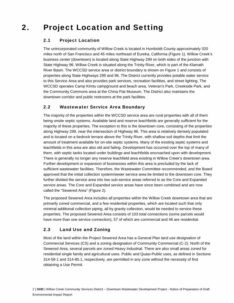
The unincorporated community of Willow Creek is located in Humboldt County approximately 320 miles north of San Francisco and 45 miles northeast of Eureka, California (Figure 1). Willow Creek’s business center (downtown) is located along State Highway 299 on both sides of the junction with State Highway 96. Willow Creek is situated along the Trinity River, which is part of the Klamath River Basin. The WCCSD service area or district boundary is shown on Figure 1 and consists of properties along State Highways 299 and 96. The District currently provides potable water service to this Service Area and also provides park services, recreation facilities, and street lighting. The WCCSD operates Camp Kimtu campground and beach area, Veteran’s Park, Creekside Park, and the Community Commons area at the China Flat Museum. The District also maintains the downtown corridor and public restrooms at the park facilities.
2.2 Wastewater Service Area Boundary
The majority of the properties within the WCCSD service area are rural properties with all of them being onsite septic systems. Available land and reserve leachfields are generally sufficient for the majority of these properties. The exception to this is the downtown core, consisting of the properties along Highway 299, near the intersection of Highway 96. This area is relatively densely populated and is located on a bedrock terrace above the Trinity River, with shallow soil depths that limit the amount of treatment available for on-site septic systems. Many of the existing septic systems and leachfields in this area are also old and failing. Development has occurred over the top of many of them, with septic tanks located under buildings and leachfields encroached upon with development. There is generally no longer any reserve leachfield area existing in Willow Creek’s downtown area. Further development or expansion of businesses within this area is precluded by the lack of sufficient wastewater facilities. Therefore, the Wastewater Committee recommended, and the Board approved that the initial collection system/sewer service area be limited to the downtown core. They further divided the service area into two sub-service areas referred to as the Core and Expanded service areas. The Core and Expanded service areas have since been combined and are now called the “Sewered Area” (Figure 2).
The proposed Sewered Area includes all properties within the Willow Creek downtown area that are primarily zoned commercial, and a few residential properties, which are located such that only minimal additional collection piping, all by gravity collection, would be needed to service these properties. The proposed Sewered Area consists of 103 total connections (some parcels would have more than one service connection), 57 of which are commercial and 46 are residential.
2.3 Land Use and Zoning
Most of the land within the Project Sewered Area has a General Plan land use designation of Commercial Services (CS) and a zoning designation of Community Commercial (C-2). North of the Sewered Area, several parcels are zoned Heavy Industrial. There are also small areas zoned for residential single family and agricultural uses. Public and Quasi-Public uses, as defined in Sections 314-58-1 and 314-85.1, respectively, are permitted in any zone without the necessity of first obtaining a Use Permit.
2 | GHD | Willow Creek Community Services District – Downtown Wastewater Development Project - Notice of Preparation of Draft
Environmental Impact Report

2.4 Demographic Trends
As of the year 2010 census (U.S. Census Bureau 2010), there were 1,710 people residing in Willow Creek (including 812 households), down from 1,743 at the 2000 census. The population density was 55.9 people per square mile. The population decreases in the winter by approximately one third to one half due to its high proportion of seasonal residents. The year-round residents are primarily composed of business people, government employees and retirees. A small percentage of residents work in the Eureka/Arcata area and commute for work. The seasonal residents are often largely involved in the outdoor recreation opportunities available during the summer. These include camping, fishing and rafting. In recent years there has been an increase in migrant workers during the late summer months that are understood to be used by the marijuana farmers.
At the time of the 2010 census, the median annual household income was $27,276 and the median income for a family was $35,720.
2.5 Environmental Setting
Willow Creek has a climate typical of inland California: warm, dry summers and cool, wet winters. The topography of the proposed Sewered Area is a mildly sloping valley, generally sloping towards Highway 96. The highest point within the collection area is near the intersection of Highway 299 and Roth Road (633 feet elevation), and the lowest point is near the intersection of Highway 96 and Mayfair Street (575 feet elevation). The topography slopes up to the north and northeast of Willow Creek’s downtown area, reaching an elevation of over 770 feet at the top of the ridge before sloping back down to the Trinity River.
The soil environment for the Project area consists mainly of loam soil types. Loam soil is a combination of sand, silt, and clay (more sand and silt than clay) that drains well and is also relatively easy to excavate. Parts of the service area consist of rocky soil, which is likely more difficult to excavate.
A key environmental resource in the Willow Creek area is the water that flows in both the Trinity River and a tributary to the Trinity River, Willow Creek. Willow Creek is the source of WCCSD’s potable water. The Trinity River is included in the federal Wild and Scenic Streams Act.
GHD | Willow Creek Community Services District – Downtown Wastewater Development Project - Notice of Preparation of
Draft Environmental Impact Report | 3

3. Project Description 3.1 Overall Concept
The proposed Project includes the following elements (Figure 3):
Collection system: Gravity wastewater collection system with one pump station (potentially two pump stations, based on final design)
Treatment system: A recirculating gravel filter treatment system located at the Mill/Stockel site
Disposal: Subsurface disposal (leachfield) at the Mill/Stockel site
Solids treatment: Onsite dewatering using a polymer injection system and a roll-off style dewatering container
The proposed Project includes a gravity wastewater collection system for the proposed Sewered Area with one pump station (potentially two pump stations, based on final design) required. Raw wastewater would ultimately be conveyed to the Mill/Stockel Site via directionally drilling through the hillside. The final design phase would include geotechnical investigations to confirm the cost effectiveness of directional drilling. If the soils show that this method would not be cost effective, then a pump station and standard force main would be constructed to convey the raw wastewater to the treatment plant. A recirculating gravel filter system would be used for treatment, and a leachfield would be used for subsurface infiltration disposal of the treated water. Solids accumulated during the treatment process would be dewatered onsite and then hauled to either a landfill or composting operation.
3.2 Project Design
3.2.1 Collection System
The collection system would be laid out to include connections to residences and businesses in the proposed Sewered Area. The majority of the system was designed to be gravity, but a pump station (potentially two pump stations, based on final design) would be necessary in two locations to convey wastewater to the Mill/Stockel Site. Per the Preliminary Engineering Report (GHD 2014), the design average dry weather flow for this Project is 38,000 gallons per day (gpd). This flow would account for both current conditions and future expansion. A peaking factor of three was used to arrive at a peak wet weather flow (highest hourly flow during the wet season) of 114,000 gpd.
A SewerCAD model was developed to assist in the design process. This model was used to determine feasible pipe slopes, trench depths, flow rates, velocities for individual sections of the system, and pumping requirements. Preliminary designs were generated to determine physical constraints and assist in cost estimating. Pressure pipes in the system would all be sized to be four inches. This would allow for the conveyance of three-inch solids, while minimizing head loss in the pipes, thereby reducing pumping requirements. All main line gravity pipes in the system would be sized to be at least six inches to adequately convey solids and prevent clogging within the system. Laterals were assumed to be four inches in diameter. In sizing gravity pipes, important considerations included velocity and capacity. With low contributing flows, pipes should be smaller so that adequate velocities are achieved to convey solids. However, gravity pipes also need to be large enough to have the capacity to convey peak wet weather flows. Most gravity pipes in the
4 | GHD | Willow Creek Community Services District – Downtown Wastewater Development Project - Notice of Preparation of Draft
Environmental Impact Report
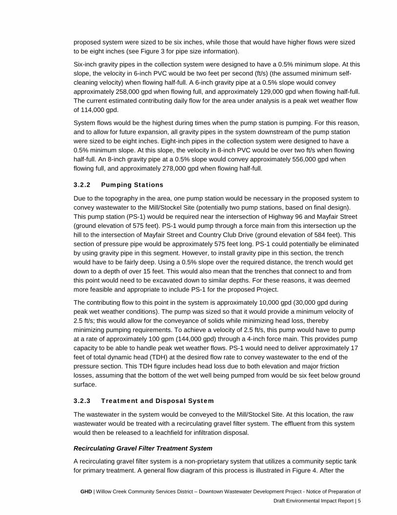
proposed system were sized to be six inches, while those that would have higher flows were sized to be eight inches (see Figure 3 for pipe size information).
Six-inch gravity pipes in the collection system were designed to have a 0.5% minimum slope. At this slope, the velocity in 6-inch PVC would be two feet per second (ft/s) (the assumed minimum self-cleaning velocity) when flowing half-full. A 6-inch gravity pipe at a 0.5% slope would convey approximately 258,000 gpd when flowing full, and approximately 129,000 gpd when flowing half-full. The current estimated contributing daily flow for the area under analysis is a peak wet weather flow of 114,000 gpd.
System flows would be the highest during times when the pump station is pumping. For this reason, and to allow for future expansion, all gravity pipes in the system downstream of the pump station were sized to be eight inches. Eight-inch pipes in the collection system were designed to have a 0.5% minimum slope. At this slope, the velocity in 8-inch PVC would be over two ft/s when flowing half-full. An 8-inch gravity pipe at a 0.5% slope would convey approximately 556,000 gpd when flowing full, and approximately 278,000 gpd when flowing half-full.
3.2.2 Pumping Stations
Due to the topography in the area, one pump station would be necessary in the proposed system to convey wastewater to the Mill/Stockel Site (potentially two pump stations, based on final design). This pump station (PS-1) would be required near the intersection of Highway 96 and Mayfair Street (ground elevation of 575 feet). PS-1 would pump through a force main from this intersection up the hill to the intersection of Mayfair Street and Country Club Drive (ground elevation of 584 feet). This section of pressure pipe would be approximately 575 feet long. PS-1 could potentially be eliminated by using gravity pipe in this segment. However, to install gravity pipe in this section, the trench would have to be fairly deep. Using a 0.5% slope over the required distance, the trench would get down to a depth of over 15 feet. This would also mean that the trenches that connect to and from this point would need to be excavated down to similar depths. For these reasons, it was deemed more feasible and appropriate to include PS-1 for the proposed Project.
The contributing flow to this point in the system is approximately 10,000 gpd (30,000 gpd during peak wet weather conditions). The pump was sized so that it would provide a minimum velocity of 2.5 ft/s; this would allow for the conveyance of solids while minimizing head loss, thereby minimizing pumping requirements. To achieve a velocity of 2.5 ft/s, this pump would have to pump at a rate of approximately 100 gpm (144,000 gpd) through a 4-inch force main. This provides pump capacity to be able to handle peak wet weather flows. PS-1 would need to deliver approximately 17 feet of total dynamic head (TDH) at the desired flow rate to convey wastewater to the end of the pressure section. This TDH figure includes head loss due to both elevation and major friction losses, assuming that the bottom of the wet well being pumped from would be six feet below ground surface.
3.2.3 Treatment and Disposal System
The wastewater in the system would be conveyed to the Mill/Stockel Site. At this location, the raw wastewater would be treated with a recirculating gravel filter system. The effluent from this system would then be released to a leachfield for infiltration disposal.
Recirculating Gravel Filter Treatment System
A recirculating gravel filter system is a non-proprietary system that utilizes a community septic tank for primary treatment. A general flow diagram of this process is illustrated in Figure 4. After the
GHD | Willow Creek Community Services District – Downtown Wastewater Development Project - Notice of Preparation of
Draft Environmental Impact Report | 5

initial settling of solids, the pre-treated wastewater flows into a recirculation tank. From there it is pumped and is applied uniformly to the gravel filters in small doses. This alternately rests and loads the gravel media, resulting in the development of a microbiological film. As the wastewater percolates down through the gravel filter, it comes into contact with this film, which oxides the waste by using it as a food source. The filter is designed for a low loading rate such that a minimum amount of solids slough off the media. The recirculation process is designed so that on average the wastewater flows through the media and then is retained in the recirculation tank for five cycles. This alternates the flow from being aerobic to anoxic/anaerobic, which results in very good rates of ammonia and nitrate removal. The filtered wastewater is contained at the bottom by an impermeable liner, and the filtrate is collected by an underdrain. The filtrate is then piped back to the recirculation tank, from which the flow is split back to the beginning of the septic tank where it is mixed with the raw sewage for denitrification. When the recirculating tank becomes full, a control valve closes and the remaining flow from the filter is discharged as effluent.
This process has been implemented in the community of Weott, and the community of Miranda has a similar facility that uses sand as the media instead of pea gravel.
Figure 4: General flow diagram of recirculating gravel filter system
The septic tank and recirculation tank were each sized at 38,000 gallons (i.e. one ADF). The detention time with a septic tank of this size would be 24 hours for the average day and eight hours under peak wet weather flow conditions. The recirculation dosing frequency would be five minutes out of every 30 minutes. BOD and TSS concentrations in the raw sewage influent are each assumed to be 300 mg/L. The gravel filters would be approximately three feet deep, with 2-inch distribution piping spaced at three feet on center. The design loading rate for the filters is three gpd/sq. ft. Using a design flow of 38,000 gpd, the required gravel filter area is about 12,700 square feet. Two 80-foot by 80-foot gravel filters would have an area of 12,800 square feet. Accounting for the treatment system itself, as well as area for a control building, office space, lab space, and additional components such as vacuum trucks, etc., the total required footprint area for this system would be approximately 45,000 square feet (slightly over an acre).
An operations building would be constructed and would be approximately 20 feet by 24 feet, single story and approximately 16 feet high. The operations building would house all the operations equipment, a restroom and storage.
6 | GHD | Willow Creek Community Services District – Downtown Wastewater Development Project - Notice of Preparation of Draft
Environmental Impact Report

Leachfield Disposal
Effluent from the recirculating gravel filter system would be pumped to a community leachfield that would also be located at the Mill/Stockel Site. The leachfield has been designed to handle 38,000 gallons of water per day (average dry weather flow). As described in the Soils Report in Appendix B of the Preliminary Engineering Report, a clean water loading rate of 1.5 gallons per day per square foot of trench surface area has been used for design. A trench size of 18 inches wide, and six feet deep, with one foot of cover, results in 11.5 square feet of exposed trench area per linear foot of trench. The necessary length of leachfield trench is therefore 2,200 feet. The leachfield would be split into six areas, each with 370 linear feet of trench. Assuming the trenches are 10 feet on center, this requires an area of about 28,000 SF. To allow for a reserve area, the amount of land acquired for the leachfield should be doubled to 56,000 SF or 1.3 acres.
The leachfield trench would consist of a gravity flow system with a 3-inch main line and 1.5 inch perforated pipe one foot below the ground surface with five feet of pea gravel below the perforated pipe for infiltration purposes. There would be both groundwater monitoring wells and leachfield monitoring wells.
3.2.4 Solids Dewatering and Disposal
During the treatment process, solids would be separated from the liquids in the community septic tank. The solids handling would consist of dewatering the solids using a batch process onsite and then hauling the dried solids, or “cake,” to either a landfill or composting operation. In this process, the septic tank solids are dewatered and not stabilized further while on site. The District would periodically need to have the dried solids hauled to either a landfill or composting operation for disposal. Currently, the landfill in Andersen, California is the nearest landfill that would accept these solids. There are also composting facilities in the Humboldt Bay area that could potentially accept these solids. The available options can and likely would change with time. Therefore, it is recommended that the District hold off on further exploring these options until it is in the final design phase of the project. At that time it may be advantageous for the District to enter into an agreement for use of these solids.
The following infrastructure would be required to integrate a dewatering system:
• Polymer injection system and mixing tank
• Sludge dewatering container
• Covered concrete holding area for dried solids
• Sludge pumps
Important design considerations include how often the septic tank would need to be pumped, how much material would need to be pumped, and how much material would need to be hauled away and disposed of at a landfill. The following assumptions were made in determining these design elements:
• Average daily flow of 38,000 gpd
• Influent TSS concentration of 220 mg/L
• 70% of the incoming TSS would settle out in the septic tank
• Over time, there would be 50% solids decomposition in the septic tank
• The sludge pumped out of the tank would contain two percent solids
GHD | Willow Creek Community Services District – Downtown Wastewater Development Project - Notice of Preparation of
Draft Environmental Impact Report | 7

• Sludge would be dewatered to 15-20 percent solids in a roll-off style container
• The treated solids would be stored on a concrete pad with a removable cover that would allow additional drying to occur. Further, the pad would allow the District to accumulate enough solids to fill a truck prior to disposal
• The analysis assumes that the only solids that would be handled by this system are those that are generated by the District’s wastewater treatment system. However, the District could use this system to also treat septage from the surrounding community. The local septic tank pumping company (Whitson’s) currently disposes of the septage they pump at a treatment plant in Hayfork
8 | GHD | Willow Creek Community Services District – Downtown Wastewater Development Project - Notice of Preparation of Draft
Environmental Impact Report

4. Environmental Issues The EIR would identify and assess the direct and indirect, significant and potentially significant environmental impacts of the proposed Project. The EIR would also evaluate the cumulative impacts of the Project when considered in conjunction with other related past, present, and reasonably foreseeable future projects.
This NOP is not accompanied by an Initial Study that screens out environmental topics because the EIR would include an analysis for all resource categories identified in Appendix G of the CEQA Guidelines including:
• Aesthetics
• Agriculture and Forestry Resources
• Air Quality
• Biological Resources
• Cultural Resources
• Geology and Soils
• Greenhouse Gas Emissions
• Hazards and Hazardous Materials
• Hydrology and Water Quality
• Land Use and Planning
• Mineral Resources
• Noise
• Population and Housing
• Public Services
• Recreation
• Transportation/Traffic
• Utilities and Service Systems
Where feasible, mitigation measures would be proposed to avoid or reduce any identified potentially significant environmental impacts attributable to the Project to a less-than-significant level. Comments received during the EIR scoping period will be considered during preparation of the EIR. Public agencies and interested organizations and persons would have an opportunity to comment on the Draft EIR after it is published and circulated for public review.
GHD | Willow Creek Community Services District – Downtown Wastewater Development Project - Notice of Preparation of
Draft Environmental Impact Report | 9

5. Permits and Approvals The Project will be subject to permits and approvals from various regulatory agencies as identified below.
Agency Permit/Approval
County of Humboldt Encroachment Permit
Caltrans Encroachment Permit
North Coast Regional Water Quality Control Board
National Pollutant Discharge Elimination System, Report of Waste Discharge
10 | GHD | Willow Creek Community Services District – Downtown Wastewater Development Project - Notice of Preparation of Draft
Environmental Impact Report
6. References U.S. Census Bureau, 2010, Profile of General Population and Housing Characteristics: 2010, accessed at http://factfinder2.census.gov/faces/tableservices/jsf/pages/productview.xhtml?src=CF
GHD, 2014, Willow Creek Community Services District Downtown Wastewater Development Preliminary Engineering Report - Wastewater Facilities, November.
GHD | Willow Creek Community Services District – Downtown Wastewater Development Project - Notice of Preparation of
Draft Environmental Impact Report | 11

THIS PAGE INTENTIONALLY LEFT BLANK

Appendices

THIS PAGE INTENTIONALLY LEFT BLANK

Appendix A - Figures


Project Planning Area
TTrriinniittyyRRiivve er r
Copyright:© 2013 National Geographic Society, i-cubed
Figure 1G:\12057 WillowCreekCSD\8410746 WCCSD-WWTP Planning\08-GIS\Maps\Figures\NOP\F1_LocationMap.mxd
0 0.5 1 1.5 2 2.5 3
Miles
© 2013. While every care has been taken to prepare this map, GHD and the Willow Creek Community Services District make no representations or warranties about its accuracy, reliability, completeness or suitability for any particular purpose and cannot accept liability and responsibility of any kind (whether in contract, tort or otherwise) for any expenses, losses, damages and/or costs (including indirect or consequential damage) which are or may be incurred by any party as a result of the map being inaccurate, incomplete or unsuitable in any way and for any reason.
Job NumberRevision A
8410746.05
Date 01 Dec 2014o Project Planning Area
Data source: ESRI Street Map. Created by:jrousseau
718 Third Street Eureka CA 95501 USA T 707 443 8326 F 707 444 8330 E [email protected] W www.ghd.com
Map Projection: Mercator Auxiliary SphereHorizontal Datum: WGS 1984
Grid: WGS 1984 Web Mercator Auxiliary Sphere
Paper Size 8.5" x 11" (ANSI A)
H u m b o l d tH u m b o l d tC o u n t yC o u n t y
P a c i f i cO
c e a n
C a l i f o r n i aC a l i f o r n i a
Ne
va
da
Ne
va
da
O r e g o nO r e g o n
Copyright:© 2014 Esri
H u m b o l d tH u m b o l d tC o u n t yC o u n t y
£¤101
T r i n i t yT r i n i t yC o u n t yC o u n t y
S i s k i y o uS i s k i y o uC o u n t yC o u n t y
T e h e m aT e h e m aC o u n t yC o u n t y
PPaa cc
ii ffii cc
OOcc ee aa nn
Fortuna
ReddingWeaverville
Garberville
Eureka
Orick
Klamath
Orleans
ProjectLocation
Arcata
£¤101
Willow Creek
UV299
UV96
UV36
UV36
£¤101
UV96
Copyright:© 2014 Esri
C a l i f o r n i a
C a l i f o r n i a
Sewered Area
WCCSD Boundary
U.S. Highway
California State Highway
Perennial Stream
Intermittent Stream
Trinity River
W i l l o w C r e e kW i l l o w C r e e k
Willow Creek Community Services DistrictDowntown Wasterwater Development ProjectNotice of Preparation


Highway 299
Highway 96
Mayfa ir S t
Coun
try
Club Dr
Will
owGl
e nThe Terrace Ln
Walnut Way
Trinity Acre s Rd
Willow
Way
RothRd Delaney Dr
The Terrace Ln
Figure 2
Job NumberRevision A
8410746.05
\\ghdnet\ghd\US\Eureka\Projects\Legacy\Projects\12057 WillowCreekCSD\8410746 WCCSD-WWTP Planning\08-GIS\Maps\Figures\NOP\F2_Potential_Service_Area.mxd
Map Projection: Lambert Conformal ConicHorizontal Datum: North American 1983
Grid: NAD 1983 StatePlane California I FIPS 0401 Feet
0 100 200 300 400 500
Feet o© 2014. While every care has been taken to prepare this map, GHD and Willow Creek Community Services District make no representations or warranties about its accuracy, reliability, completeness or suitability for any particular purpose and cannot accept liability and responsibility of any kind (whether in contract, tort or otherwise) for any expenses, losses, damages and/or costs (including indirect or consequential damage) which are or may be incurred by any party as a result of the map being inaccurate, incomplete or unsuitable in any way and for any reason.
Date 08 Dec 2014
Sewered Area Boundary
Data source: Aerial NAIP 2012, 1 m resolution. Created by:jrousseau
180 Lonsdale Street Melbourne VIC 3000 Australia T 61 3 8687 8000 F 61 3 8687 8111 E [email protected] W www.ghd.com
Paper Size ANSI A
Sewered Area
WCCSD Headquarters
Willow Creek Community Services DistrictDowntown Wasterwater Development ProjectNotice of Preparation


Figure 3
Job NumberRevision A
8410746.05
G:\12057 WillowCreekCSD\8410746 WCCSD-WWTP Planning\08-GIS\Maps\Figures\NOP\F3_CollectionTreamentSystem.mxd
Map Projection: Lambert Conformal ConicHorizontal Datum: North American 1983
Grid: NAD 1983 StatePlane California I FIPS 0401 Feeto
© 2014. While every care has been taken to prepare this map, GHD and Willow Creek Community Services District make no representations or warranties about its accuracy, reliability, completeness or suitability for any particular purpose and cannot accept liability and responsibility of any kind (whether in contract, tort or otherwise) for any expenses, losses, damages and/or costs (including indirect or consequential damage) which are or may be incurred by any party as a result of the map being inaccurate, incomplete or unsuitable in any way and for any reason.
Date 02 Dec 2014
Willow Creek Community Services DistrictDowntown Wasterwater Development ProjectNotice of Preparation
Collection, Treatment, and Disposal System
Data source: Data Custodian, Data Set Name/Title, Version/Date. Created by:jrousseau
180 Lonsdale Street Melbourne VIC 3000 Australia T 61 3 8687 8000 F 61 3 8687 8111 E [email protected] W www.ghd.com
Paper Size ANSI A
0 100 200 300 400 500
Feet


GHD Inc
718 Third Street Eureka CA 95501
T: 707-443-8326 F: 707-444-8330 E: [email protected]
© GHD Inc 2014

www.ghd.com