appendix a – fdot standard · pdf fileappendix a – fdot standard specifications ....
TRANSCRIPT

APPENDIX A –
FDOT STANDARD SPECIFICATIONS

SECTION 102MAINTENANCE OF TRAFFIC
102-1 Description.
102-2 Materials.
102-2.1 Temporary Traffic Control Devices:
102-2.2 Detour:
102-2.3 Commercial Materials for Driveway Maintenance:
102-3 Specific Requirements.102-3.1 Beginning Date of Contractor’s Responsibility:
102-3.2 Worksite Traffic Supervisor:

102-4 Alternative Traffic Control Plan.

102-5 Traffic Control. 102-5.1 Standards:
102-5.2 Maintenance of Roadway Surfaces:
102-5.3 Number of Traffic Lanes:
102-5.4 Crossings and Intersections:
102-5.5 Access for Residences and Businesses:
102-5.6 Protection of the Work from Injury by Traffic:
102-5.7 Flagger: 102-5.8 Conflicting Pavement Markings:
102-5.9 Vehicle and Equipment Visibility:
102-5.10 No Waiver of Liability:
102-6 Detours.102-6.1 General:
102-6.2 Construction:

102-6.3 Construction Methods:
102-6.4 Removal of Detours:

102-6.5 Detours Over Existing Roads and Streets:
102-6.6 Operation of Existing Movable Bridges:
102-7 Traffic Control Officer.
102-8 Driveway Maintenance. 102-8.1 General:
102-8.2 Construction Methods:
102-9 Temporary Traffic Control Devices.102-9.1 Installation and Maintenance:

102-9.2 Work Zone Signs:
102-9.3 Business Signs:
102-9.4 High Intensity Flashing Lights:
102-9.5 Warning/Channelizing Devices:

102-9.5.1 Retroreflective Collars for Traffic Cones:
102-9.5.2 Barrier Wall (Temporary):
102-9.5.3 Glare Screen (Temporary):
102-9.6 Temporary Crash Cushion (Redirective/Gating):
102-9.7 Guardrail (Temporary):
102-9.8 Arrow Board:
102-9.9 Portable Changeable Message Sign (PCMS):

102-9.10 Portable Regulatory Signs (PRS):
102-9.11 Radar Speed Display Unit (RSDU):
102-9.12 Temporary Signalization and Maintenance:
102-9.13 Temporary Traffic Detection and Maintenance:
102-9.14 Truck Mounted Attenuators and Trailer Mounted Attenuators:

102-9.15 Temporary Raised Rumble Strip Sets:
102-9.16 Automated Flagger Assistance Devices (AFAD):
102-9.17 Temporary Lane Separator:
102-10 Work Zone Pavement Marking.102-10.1 Description:
102.10.2 Painted Pavement Markings:

102-10.2.1 General:
102-10.3 Removable Tape:102-10.3.1 General:
102-10.3.2 Application:
102-10.3.3 Retroreflectivity:
102-10.3.4 Removability:
102-10.4 Temporary Retroreflective Pavement Markers (RPM’s):
102-11 Method of Measurement.102-11.1 General:
102-11.2 Traffic Control Officers:
102-11.3 Special Detours:

102-11.4 Commercial Material for Driveway Maintenance:
102-11.5 Work Zone Signs:
102-11.6. Business Signs:
102-11.7 High Intensity Flashing Lights:
102-11.8 Channelizing Devices:
102-11.9 Barrier Wall (Temporary):
102-11.10 Lights, Temporary, Barrier Wall Mount:
102-11.11 Glare Screen (Temporary):
102-11.12 Temporary Crash Cushions:102-11.12.1 Redirective:
102-11.12.2 Gating:

102-11.13 Temporary Guardrail:
102-11.14 Arrow Board:
102-11.15 Portable Changeable Message Sign:
102-11.16 Portable Regulatory Signs:
102-11.17 Radar Speed Display Unit:
102-11.18 Temporary Signalization and Maintenance:
102-11.19 Temporary Traffic Detection and Maintenance:
102-11.20 Work Zone Pavement Markings:

102-11.21 Temporary Raised Rumble Strips:
102-11.22 Temporary Lane Separator:
102-12 Submittals. 102-12.1 Submittal Instructions:
102-12.2 Contractor’s Certification of Quantities:
102-13 Basis of Payment. 102-13.1 Maintenance of Traffic (General Work):
102-13.2 Traffic Control Officers:
102-13.3 Special Detours:
102-13.4 Commercial Materials for Driveway Maintenance:
102-13.5 Work Zone Signs:
102-13.6. Business Signs:
102-13.7 High Intensity Warning Lights:

102-13.8 Channelizing Devices:
102-13.9 Barrier Wall (Temporary):
102-13.10 Lights, Temporary, Barrier Wall Mount:
102-13.11 Glare Screen (Temporary):
102-13.12 Temporary Crash Cushion (Redirective/Gating):
102-13.13 Temporary Guardrail:
102-13.14 Arrow Board:
102-13.15 Portable Changeable Message Sign:
102-13.16 Portable Regulatory Signs:
102-13.17 Radar Speed Display Unit:
102-13.18 Temporary Signalization and Maintenance:
102-13.19 Temporary Traffic Detection and Maintenance:
102-13.20 Temporary Raised Rumble Strips:
102-13.21 Work Zone Pavement Markings:
102-13.22 Temporary Lane Separator:
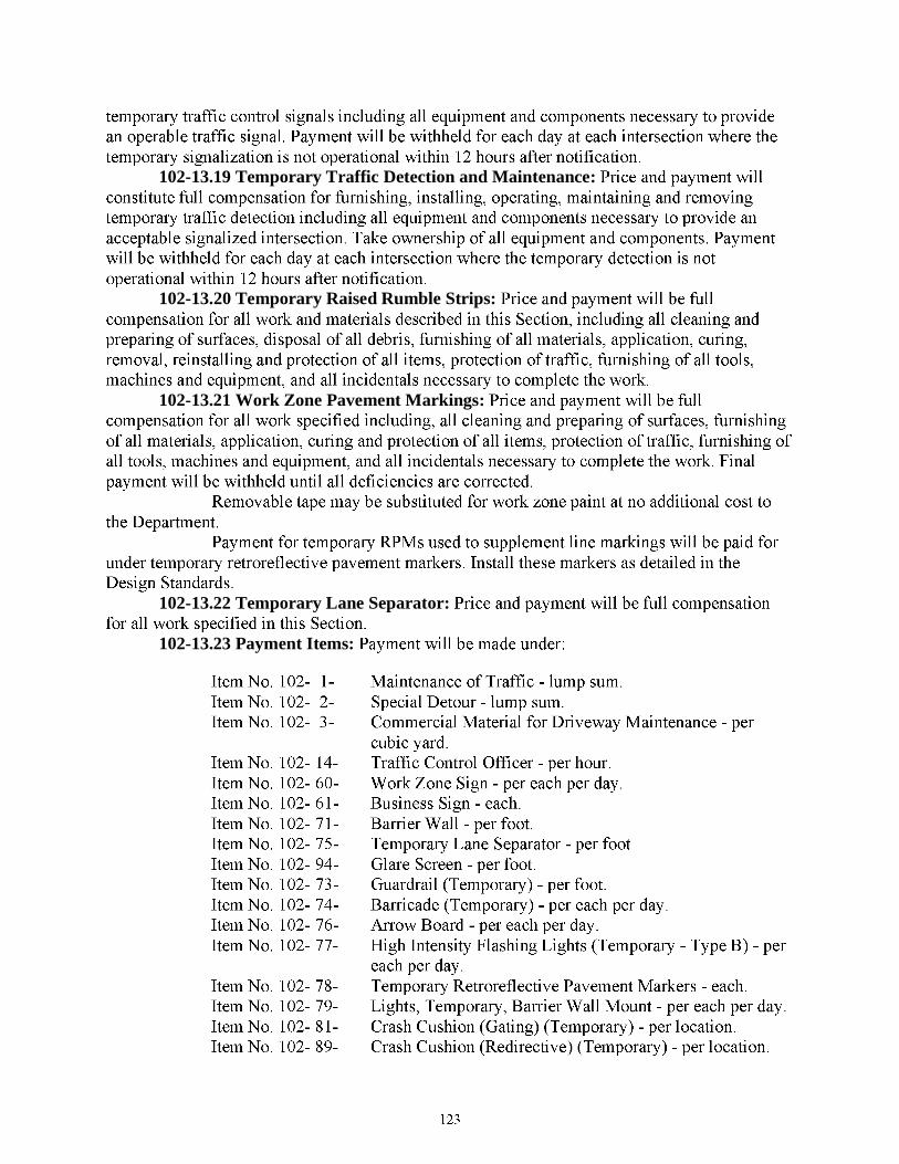
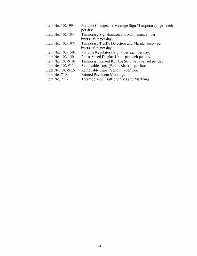
102-13.23 Payment Items:
105 CONTRACTOR QUALITY CONTROL GENERAL REQUIREMENTS. (REV 3-7-13) (FA 3-15-13) (1-14)
SECTION 105CONTRACTOR QUALITY CONTROL GENERAL REQUIREMENTS
105-1 General. 105-1.1 Quality Control Documentation.
105-1.1.1 Submission of Materials Certification and Reporting Test Results: Provide certifications prior to placement of materials. Report test results at completion of the test and meet the requirements of the applicable Specifications. 105-1.1.2 Database(s): Obtain access to the Department’s databases prior to testing and/or material placement. Database access information is available through the Department’s website. Enter all required and specified documentation and test results in the Department databases. 105-1.1.3 Worksheets: Make available to the Department, when requested, worksheets used for collecting test information. Ensure the worksheets at a minimum contain the following: a. Project Identification Number, b. Time and Date, c. Laboratory Identification and Name, d. Training Identification Numbers (TIN) and initials, e. Record details as specified within the test method. 105-1.2 Inspections to Assure Compliance with Acceptance Criteria. 105-1.2.1 General: The Department is not obligated to make an inspection of materials at the source of supply, manufacture, or fabrication. Provide the Engineer with unrestricted entry at all times to such parts of the facilities that concern the manufacture, fabrication, or production of the ordered materials. Bear all costs incurred in determining whether the material meets the requirements of these Specifications. 105-1.2.2 Quality Control Inspection: Provide all necessary inspection to assure effective Quality Control of the operations related to materials acceptance. This includes but is not limited to sampling and testing, production, storage, delivery, construction and placement. Ensure that the equipment used in the production and testing of the materials provides accurate and precise measurements in accordance with the applicable Specifications. Maintain a record of all inspections, including but not limited to, date of inspection, results of inspection, and any subsequent corrective actions taken. Make available to the Department the inspection records, when requested. 105-1.2.3 Notification of Placing Order: Order materials sufficiently in advance of their incorporation in the work to allow time for sampling, testing and inspection. Notify the Engineer, prior to placing orders for materials. Submit to the Engineer a fabrication schedule for all items requiring commercial inspection, before or at the preconstruction meeting. These items include, but are not limited to steel bridge components, overhead cantilevered sign supports with cantilevered arms exceeding 41 feet, moveable bridge components or any other item identified as an item requiring commercial inspection in the Contract Documents.
134

Notify the Engineer at least 30 days before beginning any production and include a production schedule.
105-2 Additional Requirements for Lump Sum Projects. Prepare and submit to the Engineer a project-specific list of material items and quantities to be used on the project as a Job Guide Schedule in the same format as the current Sampling, Testing, and Reporting Guide 21 calendar days prior to commencement of construction. Provide up-to-date quantities for the items on the Job Guide Schedule to the Engineer with each monthly progress estimate. The Department may not authorize payment of any progress estimate not accompanied by updated Job Guide Schedule quantities. Maintain the Job Guide Schedule throughout the project including the quantity placed since the previous submittal, and total to date quantity and any additional materials placed. Do not commence work activities that require testing until the Job Guide Schedule has been reviewed and accepted by the Engineer. At final acceptance, submit a final Job Guide Schedule that includes all materials used on the project in the same format as the monthly reports.
105-3 Quality Control Program. 105-3.1 General: Certain operations require personnel with specific qualifications. Certain materials require production under an approved Quality Control (QC) Plan to ensure that these materials meet the requirements of the Contract Documents. Applicable materials include hot mix asphalt, Portland cement concrete (Structural), earthwork, cementitious materials, timber, steel and miscellaneous metals, galvanized metal products, prestressed and/or precast concrete products and drainage products. For all applicable materials included in the Contract, submit a QC Plan prepared in accordance with the requirements of this Section to the Engineer. Do not incorporate any of these materials into the project prior to the Engineer’s approval of the QC Plan. Steel and Miscellaneous Metal products, including aluminum, are defined as the metal components of bridges, including pedestrian and moveable bridges, overhead and cantilevered sign supports, ladders and platforms, bearings, end wall grates, roadway gratings, drainage items, expansion joints, roadway decking, shear connectors, handrails, galvanized products, fencing, guardrail, light poles, high mast light poles, standard mast arm assemblies and Monotube assemblies, stay in-place forms, casing pipe, strain poles, fasteners, connectors and other hardware. When accreditation or certification is required, make supporting documents from the two previous inspections performed by the accrediting or certifying agency available to the Department upon request. Obtain Department approval prior to beginning production. Meet and maintain the approved Quality Control Program requirements at all times. Production and construction of these products without the Department’s prior approval of a Quality Control Program may result in rejection of the products. Continued approval will be subject to satisfactory results from Department evaluations, including the Independent Assurance program. In cases of non-compliance with the approved Quality Control Program, identify all affected material and do not incorporate or supply to the Department projects. The following conditions may result in suspension of a Quality Control Program: a. Failure to timely supply information required. b. Repeated failure of material to meet Standard Specification requirements.
135
c. Failure to take immediate corrective action relative to deficiencies in the performance of the Quality Control Program. d. Certifying materials that are not produced under an approved Quality Control Program for use on Department projects. e. Failure to correct any deficiencies related to any requirement of the Quality Control Program, having received notice from the Department, within the amount of time defined in the notice. 105-3.2 Compliance with the Materials Manual. Producers of Flexible Pipe shall meet the requirements of Section 6.1, Volume II of the Department’s Materials Manual, which may be viewed at the following URL: http://www.dot.state.fl.us/specificationsoffice/Implemented/URLinSpecs/Files/section61.pdf . Producers of Precast Concrete Pipe shall meet the requirements of Section 6.2, Volume II of the Department’s Materials Manual, which may be viewed at the following URL: http://www.dot.state.fl.us/specificationsoffice/Implemented/URLinSpecs/Files/section62.pdf . Producers of Precast Concrete Drainage Structures shall meet the requirements of Section 6.3, Volume II of the Department’s Materials Manual, which may be viewed at the following URL: http://www.dot.state.fl.us/specificationsoffice/Implemented/URLinSpecs/Files/section63.pdf . Producers of Precast/Prestressed Concrete Products shall meet the requirements of Sections 8.1 and 8.3 of the Department’s Materials Manual, which may be viewed at the following URLs: http://www.dot.state.fl.us/specificationsoffice/Implemented/URLinSpecs/Files/section81.pdf . http://www.dot.state.fl.us/specificationsoffice/Implemented/URLinSpecs/Files/section83.pdf . Producers of Precast Prestressed Concrete Products using Self Consolidating Concrete shall meet the requirements of Section 8.4, Volume II of the Department’s Materials Manual, which may be viewed at the following URL: http://www.dot.state.fl.us/specificationsoffice/Implemented/URLinSpecs/Files/section84.pdf Producers of Incidental Precast/Prestressed Concrete Products shall meet the requirements of Section 8.2, Volume II of the Department’s Materials Manual, which may be viewed at the following URL: http://www.dot.state.fl.us/specificationsoffice/Implemented/URLinSpecs/Files/section82.pdf . Producers of Portland Cement Concrete shall meet the requirements of Section 9.2, Volume II of the Department’s Materials Manual, which may be viewed at the following URL: http://www.dot.state.fl.us/specificationsoffice/Implemented/URLinSpecs/Files/section92.pdf . Producers of Structural Steel and Miscellaneous Metal Components shall meet the requirements of Sections 11.1, 11.2, 11.4 and 11.5 of the Department’s Materials Manual, which may be viewed at the following URLs: http://www.dot.state.fl.us/specificationsoffice/Implemented/URLinSpecs/Files/section111.pdf http://www.dot.state.fl.us/specificationsoffice/Implemented/URLinSpecs/Files/section112.pdf http://www.dot.state.fl.us/specificationsoffice/Implemented/URLinSpecs/files/Section114.pdf http://www.dot.state.fl.us/specificationsoffice/Implemented/URLinSpecs/files/Section115.pdf 105-3.3 Hot Mix Asphalt , Portland Cement Concrete (Structural), Earthwork, Cementitious Materials, Timber, Steel and Miscellaneous Metals, Galvanized Metal Products, Prestressed and/or Precast Concrete Products and Drainage Products Quality
136

Control Program: Have an accepted Quality Control Program, developed in accordance with this Section, during the production of materials to be used on Department projects.
105-3.4 Prestressed Concrete Quality Control Program: Ensure that prestressed concrete plants participating in the Department’s Acceptance Program are qualified.
Obtaining qualification requires a current certification from a Department approved precast prestressed concrete plant certification agency and a Department approved Quality Control Plan, meeting the requirements of this Section. The list of Department approved certification agencies is available on the website of the State Materials Office. 105-3.5 Steel and Miscellaneous Metals Quality Control Program: Ensure that the fabricators of Steel and miscellaneous metal products participating in the Department’s Quality Control Acceptance Program are qualified. Obtaining qualification requires an accepted Quality Control Plan, developed in accordance with this Section. A current American Institute for Steel Construction (AISC) certification is a requirement for the Quality Control Acceptance Program of the steel and miscellaneous metal fabricators, provided that AISC certification program is available for the category of the fabrication products.
105-3.6 Producers Quality Control Plan Submittal: Depending on the type of products, the producers shall submit their proposed Quality Control Plans to the State Materials Office or to the District Materials Office, as described below: 105-3.6.1 State Materials Office: Producers of cementitious materials, steel and miscellaneous metals, galvanized metal products, and aggregates must submit their proposed Quality Control Plan to the State Materials Office for review and acceptance.
105-3.6.2 District Materials Office: Producers of hot mix asphalt, Portland cement concrete (Structural), earthwork, timber, prestressed and/or precast concrete products and drainage products must submit their proposed Quality Control Plan to the local District Materials Office for acceptance. Producers located outside the State must contact the State Materials Office for address information of the District Materials Office responsible for the review of the proposed Quality Control Program. 105-3.7 Quality Control Plan Review and Acceptance: The Department will respond to the producer within 21 calendar days of receipt of the proposed Quality Control Program. The Department may perform evaluation activities to verify compliance with submitted documents prior to acceptance. If the Quality Control Program must be revised for any reason, including non-compliance, submit the revision to the Department. The Department will respond to the producer within 7 calendar days of receipt of the revised Quality Control Program. 105-3.8 Contractor’s Quality Control Plan: Have an approved Quality Control Plan meeting the requirements of this Section for the transportation, storage, placement, and other related construction operations required by the Contract Documents.
105-4 Contractor Certification of Compliance. Provide the Engineer with a notarized monthly certification of compliance with the requirements of this Section, to accompany each progress estimate, on a form provided by the Engineer. The Department may not authorize payment of any progress estimate not accompanied by an executed certification document. Final payment in accordance with 9-8 will not be made until a final notarized certification summarizing all QC exceptions has been submitted.
137

105-5 Guidelines for Development of the Quality Control Plan. 105-5.1 General: Use the following guidelines for developing the QC Plan. Provide detailed policies, methods and procedures to ensure the specified quality of all applicable materials and related production and field operations. Include other items in addition to these guidelines as necessary. 105-5.2 Personnel: 105-5.2.1 Qualifications: Submit the Training Identification Numbers (TINs) or any other information which will be traceable to the certification agency’s training location and dates for all technicians performing sampling, testing and inspection for both field and laboratory tests. Provide the names of the CTQP certifications and other pertinent certifications held and the expiration dates for each certification for each technician. Include employed and subcontracted technicians. 105-5.2.2 Level of Responsibility: Identify the primary contact for the Department. Identify roles and responsibilities of various personnel involved in the QC process. 105-5.3 Raw Materials: 105-5.3.1 Source: Identify the sources of raw materials. Provide locations and plant or mine numbers when applicable. 105-5.3.2 Certification: Describe methods of verifying compliance of certification with the specifications. 105-5.3.3 Disposition of Failing Materials: Describe the system for controlling non-conforming materials, including procedures for identification, isolation and disposition. 105-5.4 Storage Facilities for Raw Materials: Describe measures and methods, including bedding details, for preventing segregation, contamination and degradation. Describe methods of identifying individual materials. Where applicable, submit a site plan showing the locations of various materials. 105-5.5 Production Equipment: Describe calibration frequencies, maintenance schedule and procedures for production equipment.
105-5.6 Plant Requirements: 105-5.6.1 Plant Identification: For those facilities producing materials listed in
Article105-3, provide the mailing address, physical address including county and X-Y (Latitude and Longitude) coordinates of the plant, telephone and fax numbers, E-mail address, primary contact at the plant, responsible person in charge, facility number provided by the Department, Owner information and Vendor Number and other information as required. 105-5.6.2 Process Control System: Describe the methods and measures established to ensure Contract compliance for the produced materials that are supplemental to the QC sampling and testing program described in the Contract Documents. These methods and measures will include, but are not limited to, inspection schedule, additional sampling and testing, maintenance schedule, etc.
105-5.6.3 Loading and Shipping Control: Describe the methods and measures for preventing segregation, contamination and degradation during loading and shipping operations. Describe the methods established for materials to be in compliance with the specifications at the point of use.
105-5.6.4 Types of Products Generated: Describe the products the plant is approved to produce under Department guidelines.
105-5.7 Other Requirements:
138

105-5.7.1 Copy of Certification: Attach examples of certifications issued by the plant/Contractor for the products approved by the Department. 105-5.7.2 Statement of Compliance: Include a statement of compliance with all quality requirements set forth by the Department in the Contract Documents and Department manuals.
105-5.7.3 Information on Producers with Accepted Quality Control Programs: Identify the Producers of materials listed in 105-3.1 for the project. Include the Department’s Facility Id number as part of the identification. All producers must have accepted QC Programs and be listed on the Department’s List of Producers with Accepted QC Programs.
105-5.7.4 Describing Documentation Procedure: Identify location of document storage to enable Department review. Include QC charts, qualification/accreditation records, inspection reports, and other pertinent/supporting documents for an approved QC Plan. 105-5.8 Final Manufactured Product - Plant Operations: Describe inspection schedule and methods for identifying defects and non-compliance with the specifications. Describe corrective actions and methods to resolve them. 105-5.8.1 Storage: When storage of the produced materials is required and it is not defined in the Contract Documents, describe the methods and duration for storage. Include measures and methods for preventing segregation, contamination and degradation during storage. 105-5.8.2 Disposition of Failing Materials: When not described in the specifications, describe the methods and measures for identifying and controlling the failing materials. Include preventive and corrective measures. Describe disposition of failing materials. 105-5.9 Final Manufactured Product - Field Operations: 105-5.9.1 Transportation: Describe the method of delivery from the point of production/storage to the point of placement. 105-5.9.2 Storage: When storage of the produced materials is required and it is not defined in the Contract Documents, describe the methods and duration for storage. Include measures and methods for preventing segregation, contamination and degradation during storage. 105-5.9.3 Placement: Describe the methods and identify the type of equipment used in incorporation of the materials into the project. 105-5.9.4 Disposition of Failing Materials: When not described in the specifications, describe the methods and measures for identifying and controlling the failing materials. Include preventive and corrective measures. Describe disposition of failing materials. 105-5.10 Testing Laboratories: Identify the laboratories performing testing. Ensure that the testing laboratories comply with the Laboratory Qualification Program requirements of this Section.
105-6 Lab Qualification Program. Testing Laboratories participating in the Department’s Acceptance Program must have current Department qualification when testing materials that are used on Department projects. In addition, they must have one of the following: a. Current AASHTO (AAP) accreditation. b. Inspected on a regular basis per ASTM D 3740 for earthwork, ASTM D 3666 for asphalt and ASTM C 1077 for concrete for test methods used in the Acceptance Program, with all deficiencies corrected, and under the supervision of a Specialty Engineer. c. Current Construction Materials Engineering Council (CMEC) program accreditation or other independent inspection program accreditation acceptable to the Engineer and equivalent to a. or b. above.
139
After meeting the criteria described above, submit a Laboratory Qualification Application to the Department. The application is available from the Department’s website. Obtain the Department’s qualification prior to beginning testing. The Department may inspect the laboratory for compliance with the accreditation requirements prior to issuing qualification. Meet and maintain the qualification requirements at all times. Testing without Department’s qualification may result in a rejection of the test results. Continued qualifications are subject to satisfactory results from Department evaluations, including Independent Assurance evaluations. In case of suspension or disqualification, prior to resumption of testing, resolve the issues to the Department’s satisfaction and obtain reinstatement of qualification. The following conditions may result in suspension of a laboratory’s qualified status: a. Failure to timely supply required information. b. Loss of accredited status.
c. Failure to correct deficiencies in a timely manner. d. Unsatisfactory performance. e. Changing the laboratory’s physical location without notification to the accrediting agency and the Engineer. f. Delays in reporting the test data in the Department’s database. g. Incomplete or inaccurate reporting. h. Using unqualified technicians performing testing. Should any qualified laboratory falsify records, the laboratory qualification will be subject to revocation by the Engineer. Falsification of project-related documentation will be subject to further investigation and penalty under state and federal laws. It is prohibited for any contract laboratory or staff to perform Contractor Quality Control testing and any other Acceptance Program testing on the same contract.
105-7 Quality Control Plan Submittal. Submit the QC Plan to the Engineer for approval within 21 calendar days after the Contract Award. The Engineer will review the QC Plan and respond to the Contractor within 21 calendar days of receipt. If at any time the Contractor is not in compliance with the approved QC Plan, or a part thereof, affected portions of the plan will be disapproved. Cease work in the affected operation(s) and submit a revision to the Engineer. If the QC Plan, or a part thereof, must be revised, submit the revision to the Engineer. The Engineer will review the revision and respond within seven calendar days of receipt. Continue to work on operations that are still in compliance with the approved sections of the QC Plan.
105-8 Personnel Qualifications.105-8.1 General: Provide qualified personnel for sampling, testing and inspection of
materials and construction activities. Ensure that qualifications are maintained during the course of sampling, testing and inspection. Construction operations that require a qualified technician must not begin until the Department verifies that the technician is on the CTQP list of qualified technicians. The CTQP lists are subject to satisfactory results from periodic Independent Assurance evaluations. 105-8.2 QC Manager: Designate a QC Manager who has full authority to act as the Contractor’s agent to institute any and all actions necessary for the successful implementation of the QC Plan. The QC Manager must speak and understand English. The QC Manager must be
140

on-site at the project on a daily basis or always available upon four hours notice to administer the QC Plan. This includes administering, implementing, monitoring, and as necessary, adjusting the processes to ensure compliance with the Contract Documents. Ensure that the QC Manager is qualified as such through the Construction Training/Qualification Program. Under the direction of the QC Manager, and using Department’s standard forms provided by the Engineer, summarize the daily QC activities including testing and material sampling. Since erasures are strictly prohibited on all reports and forms, use blue or colored ink. Do not use black ink. If manual corrections to original data are necessary, strike through, correct, and date the entry, including the initials of the person making the correction. Make copies of the completed forms available for the Department to review daily unless otherwise required in the specifications. Ensure that the QC test data is entered into the Department’s database on a daily basis. Maintain all QC related reports and documentation for a period of three years from final acceptance of the project. Make copies available for review by the Department upon request. 105-8.3 Worksite Traffic Supervisor: Provide a Worksite Traffic Supervisor who is responsible for initiating, installing, and maintaining all traffic control devices as described in Section 102 and in the Contract Documents. Ensure that the Worksite Traffic Supervisor is certified in the advanced training category by a Department approved training Provider. Approved Providers will be posted on the Department’s website at the following URL address: http://www.dot.state.fl.us/rddesign/MOT/MOT.shtm . Use approved alternate Worksite Traffic Supervisors when necessary. 105-8.4 Flagger: Provide trained flaggers to direct traffic where one-way operation in a single lane is in effect and in other situations as required. The Worksite Traffic Supervisor or others as approved by the Department will provide training for flaggers. 105-8.5 Earthwork Quality Control Personnel: 105-8.5.1 Earthwork Level I: Ensure the technician who samples soil and earthwork materials from the roadway project, takes earthwork moisture and density readings, and records those data in the Density Log Book holds a Construction Training and Qualification Program (CTQP) Earthwork Construction Inspection Level I qualification. 105-8.5.2 Earthwork Level II: Ensure the technician responsible for determining the disposition of soil and earthwork materials on the roadway, and for interpreting and meeting Contract Document requirements holds a CTQP Earthwork Construction Inspection Level II qualification. 105-8.6 Asphalt Quality Control Personnel: 105-8.6.1 Plant Technicians: For asphalt plant operations, provide a QC technician, qualified as a CTQP Asphalt Plant Level II technician, available at the asphalt plant at all times when producing mix for the Department. Perform all asphalt plant related testing with a CTQP Asphalt Plant Level I technician. As an exception, measurements of temperature may be performed by someone under the supervision of a CTQP Plant Level II technician. 105-8.6.2 Paving Technicians: For paving operations (with the exception of miscellaneous or temporary asphalt), keep a qualified CTQP Asphalt Paving Level II technician on the roadway at all times when placing asphalt mix for the Department, and perform all testing with a CTQP Asphalt Paving Level I technician. As an exception, measurements of cross-slope, temperature, and yield (spread rate) can be performed by someone under the supervision of a CTQP Paving Level II technician at the roadway. 105-8.6.3 Mix Designer: Ensure all mix designs are developed by individuals who are CTQP qualified as an Asphalt Hot Mix Designer.
141

105-8.6.4 Documentation: Document all QC procedures, inspection, and all test results and make them available for review by the Engineer throughout the life of the Contract. Identify in the asphalt producer’s Quality Control Plan the Quality Control Manager(s) and/or Asphalt Plant Level II technician(s) responsible for the decision to resume production after a quality control failure. 105-8.7 Concrete QC Personnel: 105-8.7.1 Concrete Field Technician - Level I: Ensure technicians performing plastic property testing on concrete for materials acceptance are qualified CTQP Concrete Field Technicians Level I. Plastic property testing will include but not be limited to slump, temperature, air content, water-to-cementitious materials ratio calculation, and making and curing concrete cylinders. Duties will include initial sampling and testing to confirm specification compliance prior to beginning concrete placements, ensuring timely placement of initial cure and providing for the transport of compressive strength samples to the designated laboratories. 105-8.7.2 Concrete Field Inspector - Level II: Ensure field inspectors responsible for the quality of concrete being placed on major bridge projects are qualified CTQP Concrete Field Inspectors Level II. A Level II Inspector must be present on the jobsite during all concrete placements. Prior to the placement of concrete, the inspector will inspect the element to be cast to ensure compliance with Contract Documents. A Level II Inspector's duties may include ensuring that concrete testing, inspection, and curing in the field are performed in accordance with the Contract Documents. The QC Inspector will inform the Verification Inspector of anticipated concrete placements and LOT sizes. 105-8.7.3 Concrete Laboratory Technician – Level I: Ensure technicians testing cylinders and recording concrete strength for material acceptance are qualified CTQP Concrete Laboratory Technicians Level I. Duties include final curing, compressive strength testing, and the recording/reporting of all test data. 105-8.8 Supervisory Personnel – Post-Tensioned and Movable Bridge Structures:
105-8.8.1 General: Provide supervisory personnel meeting the qualification requirements only for the post-tensioned and movable bridge types detailed in this Article. Submit qualifications to the Engineer at the pre-construction conference. Do not begin Construction until the qualifications of supervisory personnel have been approved by the Engineer. 105-8.8.2 Proof of License or Certification: Submit a copy of the Professional Engineer license current and in force issued by the state in which registration is held. The license must be for the field of engineering that the construction work involves such as Civil, Electrical or Mechanical. Under certain circumstances Florida registration may be required. Submit a copy of the license issued by the State of Florida for tradesmen that require a license indicating that the license is in force and is current. Submit a copy of the certification issued by the Instrumentation, Systems and Automation Society of America for each Certified Control Systems Technician. 105-8.8.3 Experience Record: Submit the following information for supervisory personnel to substantiate their experience record. The supervisor (project engineer, superintendent/manager or foreman) seeking approval must provide a notarized certification statement attesting to the completeness and accuracy of the information submitted. Provide the following experience information for each individual seeking approval as a supervisor:
142

Project owner’s name and telephone number of an owner’s representative, project identification number, state, city, county, highway number and feature intersected. Provide a detailed description of each bridge construction experience, and the level of supervisory authority during that experience. Report the duration in weeks, as well as begin and end dates, for each experience period. Provide the name, address and telephone number of an individual that can verify that the experience being reported is accurate. This individual should have been an immediate supervisor unless the supervisor cannot be contacted in which case another individual with direct knowledge of the experience is acceptable. 105-8.8.4 Concrete Post-Tensioned Segmental Box Girder Construction: Ensure the individuals filling the following positions meet the minimum requirements as follows: 105-8.8.4.1 Project Engineer-New Construction: Ensure the Project Engineer is a registered professional engineer with five years of bridge construction experience. Ensure a minimum of three years of experience is in Segmental Box Girder Construction Engineering and includes a minimum of one year in segmental casting yard operations and related surveying, one year in segment erection and related surveying, including post-tensioning and grouting of longitudinal tendons and a minimum of one year as the Project Engineer in responsible charge of Segmental Box Girder Construction Engineering. Ensure this individual is present at the site of construction, at all times while segmental box girder construction or segment erection is in progress. 105-8.8.4.2 Project Engineer-Repair and Rehabilitation: Ensure the Project Engineer is a registered Professional Engineer with five years of bridge construction experience. Ensure a minimum of three years of experience is in Segmental Box Girder Construction Engineering and includes one year of post-tensioning and grouting of longitudinal tendons and a minimum of one year as the Project Engineer in responsible charge of Segmental Box Girder rehabilitation engineering or Segmental Box Girder new construction engineering. 105-8.8.4.3 Project Superintendent/Manager-New Construction: Ensure the Project Superintendent/Manager has a minimum of ten years of bridge construction experience or is a registered professional engineer with five years of bridge construction experience. Ensure that a minimum of three years of experience is in Segmental Box Girder construction operations and includes a minimum of one year in the casting yard operations and related surveying, one year in segment erection and related surveying including post-tensioning and grouting of longitudinal tendons and a minimum of one year as the Project Superintendent/Manager in responsible charge of Segmental Box Girder construction operations. Ensure this individual is present at the site of construction, at all times while segmental box girder construction or segment erection is in progress. 105-8.8.4.4 Project Superintendent/Manager-Repair and Rehabilitation: Ensure the Project Superintendent/Manager has a minimum of five years of bridge construction experience or is a registered professional engineer with three years of bridge construction experience. Ensure that a minimum of two years of experience is in Segmental Box Girder construction operations and includes a minimum of one year experience performing post-tensioning and grouting of longitudinal tendons and a minimum of one year as the Project Superintendent/Manager in responsible charge of Segmental Box Girder rehabilitation operations or Segmental Box Girder new construction operations. 105-8.8.4.5 Foreman-New Construction: Ensure that the Foreman has a minimum of five years of bridge construction experience with two years of experience in
143

Segmental Box Girder Operations and a minimum of one year as the foreman in responsible charge of Segmental Box Girder new construction Operations. Ensure this individual is present at the site of construction, at all times while segmental box girder construction or segment erection is in progress. 105-8.8.4.6 Foreman-Repair and Rehabilitation: Ensure the Foremen has a minimum of five years of bridge construction experience with two years of experience in Segmental Box Girder Operations and a minimum of one year as the foreman in responsible charge of Segmental Box Girder rehabilitation operations or Segmental Box Girder new construction operations. 105-8.8.4.7 Geometry Control Engineer/Manager: Ensure that the Geometry Control Engineer/Manager for construction of cast-in-place box segments is a Registered Professional Engineer with one year of experience, a non-registered Engineer with three years of experience or a Registered Professional Land Surveyor with three years of experience in geometry control for casting and erection of cast-in-place box segments. Credit for experience in cast-in-place box girder geometry control will be given for experience in precast box girder geometry control but not vice versa. Ensure that the Geometry Control Engineer/Manager for precast box segments is a Registered Professional Engineer with one year of experience or non-registered with three years of experience in casting yard geometry control of concrete box segments. The Geometry Control Engineer/Manager must be responsible for and experienced at implementing the method for establishing and maintaining geometry control for segment casting yard operations and segment erection operations and must be experienced with the use of computer programs for monitoring and adjusting theoretical segment casting curves and geometry. This individual must be experienced at establishing procedures for assuring accurate segment form setup, post-tensioning duct and rebar alignment and effective concrete placement and curing operations as well as for verifying that casting and erection field survey data has been properly gathered and recorded. Ensure this individual is present at the site of construction, at all times while cast-in-place segmental box girder construction is in progress or until casting yard operations and segment erection is complete.
105-8.8.4.8 Surveyor: Ensure that the Surveyor in charge of geometry control surveying for box segment casting and/or box segment erection has a minimum of one year of bridge construction surveying experience. Ensure this individual is present at the site of construction, at all times while segmental box girder construction or segment erection is in progress. 105-8.8.5 Movable Bridge Construction: Ensure the individual filling the following positions meet the minimum requirements as follows: 105-8.8.5.1 Electrical Journeyman: Ensure the Electrical Journeyman holds, an active journeyman electrician’s license and has at least five years experience in industrial electrical work, or is a Certified Control Systems Technician. A Certified Control Systems Technician will not be permitted to perform electrical power work including, but not limited to, conduit and wire-way installation or power conductor connection. Ensure the electrical journeyman has successfully completed the installation of one similar movable bridge electrical system during the last three years. 105-8.8.5.2 Control Systems Engineer and Mechanical Systems Engineer: Ensure the Control Systems Engineer and Mechanical Systems Engineer are both
144

registered Professional Engineers with a minimum of 10 years supervisory experience each in movable bridge construction. Ensure the Engineers have working knowledge of the movable bridge leaf motion control techniques, mechanical equipment and arrangements specified for this project. Ensure that each Engineer has been in responsible control of the design and implementation of at least three movable bridge electrical control and machinery systems within the past 10 years of which, at least one of the three bridges was within the last three years. Ensure that a minimum of one of the three bridge designs incorporated the same type of leaf motion control and machinery systems specified for this project.
105-8.8.6 Concrete Post-Tensioned Other Than Segmental Box Girder Construction: Ensure the individual filling the following positions meet the minimum requirements as follows: 105-8.8.6.1 Project Engineer: Ensure the Project Engineer is a registered Professional Engineer with five years of bridge construction experience. Ensure that a minimum of three years of experience is in concrete post-tensioned construction. Ensure that the three years of experience includes experience in girder erection, safe use of cranes, stabilization of girders; design of false work for temporary girder support, post-tensioning and grouting operations, and a minimum of one year as the Project Engineer in responsible charge of post-tensioning related engineering responsibilities.
105-8.8.6.2 Project Superintendent/Manager: Ensure the Project Superintendent/Manager has a minimum of ten years of bridge construction experience or is a registered Professional Engineer with five years of bridge construction experience and has a minimum of three years of supervisory experience in girder erection, safe use of cranes, stabilization of girders; design of falsework for temporary girder support post-tensioning, grouting operations and a minimum of one year as the Project Superintendent/Manager in responsible charge of post-tensioning related operations.
105-8.8.6.3 Foreman: Ensure the Foremen has a minimum of five years of bridge construction experience with two years of experience in post-tensioning related operations and a minimum of one year as the foreman in responsible charge of post-tensioning related operations. 105-8.8.7 Post-Tensioning (PT) and Grouting Personnel Qualifications: Perform all stressing and grouting operations in the presence of the Engineer and with personnel meeting the qualifications of this article. Coordinate and schedule all PT and grouting activities to facilitate inspection by the Engineer 105-8.8.7.1 Post-Tensioning: Perform all PT field operations under the direct supervision of a Level II CTQP Qualified PT Technician who must be present at the site of the post-tensioning work during the entire duration of the operation. For the superstructures of bridges having concrete post-tensioned box or I girder construction, provide at least two CTQP qualified PT technicians, Level I or II, on the work crew. The supervisor of the work crew, who must be a Level II CTQP Qualified PT Technician, may also be a work crew member, in which case, the supervisor shall count as one of the two CTQP qualified work crew members. For PT operations other than the superstructures of post-tensioned box or I girder construction, perform all PT operations under the direct supervision of a Level II CTQP Qualified PT Technician who must be present at the site of the PT work during the entire duration of the operation. Work crew members are not required to be CTQP qualified. 105-8.8.7.2 Grouting: Perform all grouting field operations under the direct supervision of a Level II CTQP Qualified Grouting Technician who must be present at the
145

site of the grouting work during the entire duration of the operation. For the superstructures of bridges having concrete post-tensioned box or I girder construction, provide at least two CTQP qualified grouting technicians, Level I or II, on the work crew. The supervisor of the work crew, who must be a Level II CTQP Qualified Grouting Technician, may also be a work crew member, in which case, the supervisor shall count as one of two CTQP qualified work crew members. For grouting operations other than the superstructures of post-tensioned box or I girder construction, perform all grouting operations under the direct supervision of a Level II CTQP Qualified Grouting Technician who must be present at the site of the grouting work during the entire duration of the operation. Work crew members are not required to be CTQP qualified. Perform all vacuum grouting operations under the direct supervision of a crew foreman who has been trained and has experience in the use of vacuum grouting equipment and procedures. Submit the crew foreman’s training and experience records to the Engineer prior to performing any vacuum grouting operation. 105-8.8.8 Failure to Comply with Bridge Qualification Requirements: Make an immediate effort to reestablish compliance. If an immediate effort is not put forth as determined by the Engineer, payment for the bridge construction operations requiring supervisors to be qualified under this Specification will be withheld up to 60 days. Cease all bridge construction and related activities (casting yard, etc.) if compliance is not met within 60 days, regardless of how much effort is put forth. Resume bridge construction operations only after written approval from the Engineer stating that compliance is reestablished. 105-8.9 Prestressed Concrete Plant Quality Control Personnel: Ensure each prestressed concrete plant has an onsite production manager, an onsite Plant Quality Control Manager, a Plant engineer, and adequate onsite QC inspectors/technicians to provide complete QC inspections and testing. Ensure the Plant Manager for QC has at least five years of related experience and a current PCI QC personnel Level III certification and a certificate of completion of Section 450 Specification examination. Ensure that the QC inspector/technician has current PCI QC Technician/Inspector Level II certification and a certificate of completion of Section 450 Specification examination. Ensure that the batch plant operators of the ready mixed concrete batch plants meet the requirements of Section 9.2 of the Materials Manual. Ensure that the batch plant operators of the onsite centrally mixed concrete plants meet the requirements of 105-8.11.1.4.2.
105-8.10 Signal Installation Inspector: Provide an inspector trained and certified by the International Municipal Signal Association (IMSA) as a Traffic Signal Inspector to perform all signal installation inspections. Use only Department approved signal inspection report forms during the signal inspection activities. Ensure all equipment, materials, and hardware is in compliance with Department Specifications and verify that all equipment requiring certification is listed on the Department’s Approved Product List (APL). Provide the completed signal inspection report form(s), certified by the IMSA Traffic Signal Inspector to the Engineer. The Department’s approved inspection report forms are available at the following URL: http://www.dot.state.fl.us/trafficoperations/ . 105-8.11 Pipe and Precast Concrete Products Manufacturing Facilities Quality Control Personnel: 105-8.11.1 General: Obtain personnel certifications from Department accredited training providers. The list of Department approved courses and their accredited providers is available on the State Materials Office website.
146

105-8.11.2 Precast Concrete Drainage Structures, Precast Concrete Box Culvert, Precast Concrete Pipe, Incidental Precast Concrete, and Flexible Pipe Manufacturing Facilities Quality Control Personnel: 105-8.11.2.1 Level I Quality Control Inspectors: Ensure that the Level I Inspectors have completed a minimum of a 12-hour, Department approved, Level I QC Inspector training course in the respective work area. As an exception to this, ensure Flexible Pipe Level I QC Inspectors have completed a minimum of an 8-hour, Department approved, Level I QC Flexible Pipe Inspector training course. For Incidental Precast Concrete, as an alternative to the completion of the 12-hour training course, the Department will accept QC personnel meeting the requirements of 105-8.11.2.4.1 and CTQP Concrete Field Technician level I certification or Precast/Prestressed Concrete Institute (PCI) Quality Control Technician/Inspector Level II certification. 105-8.11.2.2 Level II Quality Control Inspectors: Ensure that Level II Inspectors have completed Department approved Level I QC Inspector training and a minimum of a 5-hour, Department approved, Level II QC Inspector training course in the respective work areas. For Incidental Precast Concrete, as an alternative to the completion of the 5-hour training course, the Department will accept CTQP Concrete Field Technician Level II or PCI Quality Control Level III certifications. 105-8.11.2.3 Plant Quality Control Manager: Ensure that QC Manager has completed Department approved Level II QC Inspector training and has a minimum of 2 years construction related experience in the specific work area. 105-8.11.2.4 Additional Requirements for Quality Control Personnel of Precast Concrete Drainage, Precast Concrete Box Culvert, and Incidental Precast Concrete Manufacturing Facilities: 105-8.11.2.4.1 Testing Personnel: Ensure the personnel performing plastic property tests have ACI Concrete Field Testing Technician-Grade I certification. Ensure the personnel performing laboratory compressive strength testing have ACI Concrete Laboratory Testing Technician-Grade 1 certification or ACI Concrete Strength Testing Technician certification. 105-8.11. 2.4.2: Batch Plant Operator: Ensure the concrete batch plant operator is qualified as a CTQP Concrete Batch Plant Operator. As an alternative to CTQP qualification, the Department will accept the completion of a minimum of a 6-hour, Department approved, Batch Plant Operator training course. 105-8.12 Structural Steel and Miscellaneous Metals Fabrication Facility Quality Control Personnel: Ensure each fabrication facility has an onsite production manager, an onsite facility manager for QC, a plant engineer, and on site QC inspectors/technicians to provide complete QC inspections and testing. Ensure that the Facility Manager for QC and QC inspectors/technicians meet the certification requirements set forth in the latest version of AASHTO/NSBA Steel Bridge Collaboration S 4.1, Steel Bridge Fabrication QC/QA Guide Specification, including the years of experience required in Table 105-5 below. The Facility Manager for QC must meet the requirements of Table 105-5 for every Structural Steel Member Type produced by a plant with QC being managed by the Facility Manager for QC. The Facility Manager for QC will report directly to the plant manager or plant engineer and must not be the plant production manager nor report to or be the subordinate of the plant production manager. QC inspectors/technicians must be the employees of, and must report directly to the Facility Manager for QC.
147

TABLE 105-5 Experience Requirements for QC Inspectors/Technicians And Facility Manager for Quality Control
Structural Steel Member Type Minimum Years of Experience Required QC Inspector/Technician Facility Manager for QC
Rolled beam bridges 1 year 3 years Welded plate girders (I sections, box sections, etc.) 2 years 4 years
Complex structures, such as trusses, arches, cable stayed bridges, and moveable bridges
3 years 5 years
Fracture critical (FC) members 3 years 5 years
148

SECTION 234SUPERPAVE ASPHALT BASE
234-1 Description.
234-2 Materials. 234-2.1 General:
234-2.2 Reclaimed Asphalt Pavement (RAP):
234-3 General Composition of Mixture.234-3.1 General:
234-3.2 Mix Design:
234-3.2.1 Gradation Classification: 234-3.2.2 Aggregate Consensus Properties:
234-3.2.3 Mix Design Revisions:
234-4 Contractor’s Process Control.
234-5 Acceptance of the Mixture.
234-6 Plant, Methods and Equipment.
234-6.1 Paving Equipment:

234-6.2 Compaction Equipment:
234-7 Construction Requirements. 234-7.1 General:
234-7.1.1 Temperature Limitations:
234-7.1.2 Tack Coat:.
234-7.1.3 Thickness of Layers:
234-8 Thickness Requirements. 234-8.1 General:
234-8.2 Spread Rate Tolerance:
234-8.3 Allowable Deficiencies:
234-8.4 Pavement Exceeding Allowable Deficiency in Spread Rate:

234-8.5 Correcting Deficiency by Adding New Surface Material:
234-9 Method of Measurement.
234-10 Basis of Payment.
SECTION 300PRIME AND TACK COATS
300-1 Description.
300-2 Materials.300-2.1 Prime Coat:
300-2.2 Cover Material for Prime Coat:
300-2.3 Tack Coat:
237

300-3 Equipment.300-3.1 Pressure Distributor:
300-3.2 Sampling Device:
300-3.3 Temperature Sensing Device:
300-4 Contractor’s Quality Control.
300-5 Cleaning Base and Protection of Adjacent Work.
300-6 Weather Limitations.
238
300-7 Application of Prime Coat.300-7.1 General:
300-7.2 Rate of Application: 300-7.2.1 Limerock, Limerock Stabilized, and Local Rock Bases:
300-7.2.2 Sand-Clay, Shell and Shell Stabilized Bases:
300-7.3 Sprinkling:
300-7.4 Partial Width of Application:
300-8 Application of Tack Coat. 300-8.1 General:
300-8.2 Where Required:
300-8.3 Method of Application:
300-8.4 Rate of Application:
239

300-8.5 Curing and Time of Application:
300-8.6 Protection:
300-9 Method of Measurement.300-9.1 General:
300-9.2 Calibration of Tanks:
300-9.3 Temperature Correction:
1+60)-(T KV = V
1
240

300-10 Basis of Payment.
241

SECTION 320HOT MIX ASPHALT -
PLANT METHODS AND EQUIPMENT
320-1 General. This Section specifies the basic equipment and operational requirements for hot mix asphalt (including warm mix asphalt) production facilities used in the construction of asphalt pavements and bases. Establish and maintain a quality control system that provides assurance that all materials and products submitted for acceptance meet Contract requirements.
320-2 Quality Control (QC) Requirements. 320-2.1 Minimum Producer QC Requirements: Perform as a minimum the following activities: 1. Stockpiles: a. Assure materials are placed in the correct stockpile; b. Assure good stockpiling techniques; c. Inspect stockpiles for separation, contamination, segregation, and other similar items; d. Properly identify and label each stockpile. 2. Incoming Aggregate: a. Obtain gradations and bulk specific gravity (Gsb
b. Determine the gradation of all component materials and routinely compare gradations and G
) values from aggregate supplier for reference;
sb3. Cold Bins:
values to mix design.
a. Calibrate the cold gate/feeder belt for each material; b. Determine cold gate/feeder belt settings; c. Observe operation of cold feeder for uniformity; d. Verify accuracy of all settings; e. Verify that the correct components are being used, and that all modifiers or additives or both are being incorporated into the mix. 4. Batch Plants: a. Determine percent used and weight to be pulled from each bin to assure compliance with the mix design; b. Check mixing time; c. Check operations of weigh bucket and scales. 5. Drum Mixer Plants: a. Determine aggregate moisture content; b. Calibrate the weigh bridge on the charging conveyor. 6. Control Charts: Maintain QC data and charts (updated daily) for all QC Sampling and Testing and make available upon demand. Provide the following charts: a. All components used to determine the composite pay factor (No. 8 sieve, No. 200 sieve, asphalt binder content, air voids, and density); b. Gradation of incoming aggregate; c. Gradation, asphalt binder content and maximum specific gravity (Gmm) of RAP;
242

d. Any other test result or material characteristic (as determined by the Contractor) necessary for process control. The above listed minimum activities are to be considered normal activities necessary to control the production of hot mix asphalt at an acceptable quality level. Depending on the type of process or materials, some of the activities listed may not be necessary and in other cases, additional activities may be required. The frequency of these activities will also vary with the process and the materials. When the process varies from the defined process average and variability targets, the frequency of these activities will be increased until the proper conditions have been restored. 320-2.2 Minimum Process Control Testing Requirements: Perform, as a minimum, the following activities at the testing frequencies provided in Table 320-1. QC tests used in the acceptance decision may be used to fulfill these requirements.
Table 320-1 Asphalt Plant - Materials Testing Frequencies
Material Property Minimum Testing Frequency
Aggregate Gradation Once per 1,000 tons of incoming aggregate
Asphalt Mix Asphalt Binder Content If daily production > 100 tons, once per day; If daily production > 1,000 tons,
twice per day. *
Asphalt Mix Bulk Specific Gravity (Gmb
If daily production > 100 tons, once per day; If daily production > 1,000 tons,
twice per day. * )
Asphalt Mix Gradation If daily production > 100 tons, once per day; If daily production > 1,000 tons,
twice per day. *
Asphalt Mix Maximum Specific Gravity (Gmm
If daily production > 100 tons, once per day; If daily production > 1,000 tons,
twice per day. * )
Asphalt Mix Temperature Each of first 5 loads, then once every
5 loads thereafter, per day per mix design.
RAP Asphalt Binder Content Once per 1,000 tons RAP RAP Gradation Once per 1,000 tons RAP RAP Maximum Specific Gravity (Gmm Once per 5,000 tons RAP )
*If less than 100 tons of mix is produced on each of successive days of production, resulting in a cumulative quantity of greater than 100 tons, then perform the indicated test.
320-2.3 Personnel Qualifications: Provide QC Technicians in accordance with Section 105.
320-2.4 Hot Mix Asphalt Testing Laboratory Requirements: Furnish a fully equipped asphalt laboratory at the production site. The laboratory must be qualified under the Department’s Laboratory Qualification Program, as described in Section 105. In addition, the laboratory shall meet the following requirements:
243

1. Area - The effective working area of the laboratory shall be a minimum of 180 square feet, with a layout of which will facilitate multiple tests being run simultaneously by two technicians. This area does not include the space for desks, chairs and file cabinets. Any variations shall be approved by the Engineer. 2. Lighting - The lighting in the lab must be adequate to illuminate all areas of the work. 3. Temperature Control - Equip the lab with heating and air conditioning units that provide a satisfactory working environment.
4. Ventilation - Equip the lab with exhaust fans that will remove all hazardous fumes from within the laboratory in accordance with OSHA requirements. 5. Equipment and Supplies - Furnish the lab with the necessary sampling and testing equipment and supplies for performing contractor QC and Department Verification Sampling and Testing. A detailed list of equipment and supplies required for each test is included in the appropriate FDOT, AASHTO, or ASTM Test Method. In the event testing equipment goes out of service during production, the Contractor may elect to use replacement equipment at another laboratory qualified, as described in Section 105, for up to 72 hours upon notification of the Engineer. 6. Personal Computer - Provide a personal computer capable of running a Microsoft ExcelTM
7. Communication - Provide a telephone and fax machine (with a private line) for the use of the testing facility’s QC personnel. In addition, provide an internet connection capable of uploading data to the Department’s database and for e-mail communications.
spreadsheet program, along with a printer.
320-3 Requirements for All Plants. 320-3.1 General: Design, manufacture, coordinate, and operate the asphalt plant in a manner that will consistently produce a mixture within the required tolerances and temperatures specified. 320-3.2 Electronic Weigh Systems: Equip the asphalt plant with an electronic weigh system that: 1) has an automatic printout, 2) is certified every six months by an approved certified scale technician, and 3) meets monthly comparison checks with certified truck scales as specified in 320-3.2.4. Weigh all plant produced hot mix asphalt on the electronic weigh system, regardless of the method of measurement for payment. Include, as a minimum, the following information on the printed delivery ticket: (a) Sequential load number (b) Project number (c) Date (d) Name and location of plant (e) Mix design number (f) Place for hand-recording mix temperature (g) Truck number (h) Gross, tare, and net tonnage per truck (as applicable) (i) Daily total tonnage of mix for the mix design Print the delivery ticket with an original and at least one copy. Furnish the original to the Engineer at the plant and one copy to the Engineer at the paving site. Utilize any one of the following three electronic weigh systems. 320-3.2.1 Electronic Weigh System on the Truck Scales: Provide an electronic weigh system on all truck scales, which is equipped with an automatic recordation system that is
244
approved by the Engineer. Use scales of the type that directly indicate the total weight of the loaded truck. Use scales meeting the requirements for accuracy, condition, etc., of the Bureau of Weights and Measures of the Florida Department of Agriculture, and re-certify such fact every six months, either by the Bureau of Weights and Measures or by a registered scale technician. 320-3.2.2 Electronic Weigh System on Hoppers Beneath a Surge or Storage Bin: Provide an electronic weigh system on the hopper (hopper scales or load cells) beneath the surge or storage bin, which is equipped with an automatic recordation system approved by the Engineer.
320-3.2.3 Automatic Batch Plants with Printout: For batch plants, provide an approved automatic printer system which will print the individual or cumulative weights of aggregate and liquid asphalt delivered to the pugmill and the total net weight of the asphalt mix measured by hopper scales or load cell type scales. Use the automatic printer system only in conjunction with automatic batching and mixing control systems that have been approved by the Engineer.
320-3.2.4 Monthly Electronic Weigh System Comparison Checks: Check the accuracy of the electronic weighing system at the commencement of production and thereafter at least every 30 days during production by one of the following two methods and maintain a record of the weights in the Scale Check Worksheet. 320-3.2.4.1. Electronic Weigh System on Truck Scales:
(a) The Engineer will randomly select a loaded truck of asphalt mix, a loaded aggregate haul truck, or another vehicle type approved by the Engineer and record the truck number and gross weight from the Contractor’s delivery ticket. (b) Weigh the selected truck on a certified truck scale, which is not owned by the Contractor and record the gross weight for the comparison check. If another certified truck scale is not available, the Engineer may permit another set of certified truck scales owned by the Contractor to be used. The Engineer may elect to witness the scale check. (c) The gross weight of the loaded truck as shown on the Contractor’s delivery ticket will be compared to the gross weight of the loaded truck from the other certified truck scale. The maximum permissible deviation is 8 pounds per ton of load, based on the certified truck scale weight. (d) If the distance from the asphalt plant to the nearest certified truck scale is enough for fuel consumption to affect the accuracy of the comparison checks, a fuel adjustment may be calculated by using the truck odometer readings for the distance measurement, and 6.1 miles per gallon for the fuel consumption rate, and 115 ounces per gallon for fuel weight. (e) During production, when an additional certified truck scale is not available for comparison checks, the Engineer may permit the Contractor to weigh the truck on his certified scales used during production and then weigh it on another certified truck scale, as soon the other scale is available for the comparison checks. In addition to the periodic checks as specified above, check the scales at any time the accuracy of the scales becomes questionable. When such inaccuracy does not appear to be sufficient to seriously affect the weighing operations, the Engineer will allow a period of two calendar days for the Contractor to conduct the required scale check. However, in the event the indicated inaccuracy is sufficient to seriously affect the mixture, the Engineer may require immediate shut-down until the accuracy of the scales has been checked and necessary
245
corrections have been made. Include the cost of all scale checks in the bid price for asphalt concrete, at no additional cost to the Department. 320-3.2.4.2. Electronic Weigh System on Hoppers Beneath a Surge or Storage Bin and Automatic Batch Plants with Printout:
(a) The Engineer will randomly select a loaded truck of asphalt mix and record the truck number, and the net weight of the asphalt mix from the Contractor’s delivery ticket. (b) Weigh the selected truck on a certified truck scale, which is not owned by the Contractor and record the gross weight for the comparison check. If another certified truck scale is not available, the Engineer may permit another set of certified truck scales owned by the Contractor to be used. The Engineer may elect to witness the scale check.
(c) Deliver the asphalt mix to the project, then weigh the selected empty truck on the same certified truck scales. Record the tare weight of the truck. (d) Compare the net weight of the asphalt mix from the delivery ticket to the calculated net weight of the asphalt mix as determined by the certified truck scale weights. The maximum permissible deviation is 8 pounds per ton of load, based on the certified truck scale weight. (e) Use the fuel adjustment as specified in 320-3.2.4.1(d), when the distance from the asphalt plant to the nearest certified truck scale is enough for fuel consumption to affect the accuracy of the comparison checks. (f) During production, when an additional certified truck scale is not available for comparison checks, the Engineer may permit the Contractor to load a truck with aggregate from the pugmill, surge or storage bin, and follow the above procedures to conduct the comparison checks as soon as certified truck scale is available. If the check shows a greater difference than the tolerance specified above, then recheck on a second set of certified scales. If the check and recheck indicate that the printed weight is out of tolerance, have a certified scale technician check the electronic weigh system and certify the accuracy of the printer. While the system is out of tolerance and before its adjustment, the Engineer may allow the Contractor to continue production only if provisions are made to use a set of certified truck scales to determine the truck weights. 320-3.3 Asphalt Binder: Meet the following requirements: 320-3.3.1 Transportation: Deliver the asphalt binder to the asphalt plant at a temperature not to exceed 370°F, and equip the transport tanks with sampling and temperature sensing devices meeting the requirements of 300-3.2. 320-3.3.2 Storage: Equip asphalt binder storage tanks to heat the liquid asphalt binder to the temperatures required for the various mixtures. Heat the material in such a manner that no flame comes in contact with the binder. Heat or insulate all pipe lines and fittings. Use a circulating system of adequate size to ensure proper and continuous circulation during the entire operating period. Locate a thermometer, reading from 200 to 400°F, either in the storage tank or in the asphalt binder feed line. Maintain the asphalt binder in storage within a range of 230 to 370°F in advance of mixing operations. Locate a sampling device on the discharge piping exiting the storage tank or at a location as approved by the Engineer. 320-3.4 Aggregate: Meet the following requirements: 320-3.4.1 Stockpiles: Place each aggregate component in an individual stockpile, and separate each from the adjacent stockpiles, either by space or by a system of bulkheads.
246

Prevent the intermingling of different materials in stockpiles at all times. Identify each stockpile, including RAP, as shown on the mix design.
Form and maintain stockpiles in a manner that will prevent segregation. If a stockpile is determined to be segregated, discontinue the use of the material on the project until the appropriate actions have been taken to correct the problem. 320-3.4.2 Blending of Aggregates: Stockpile all aggregates prior to blending or placing in the cold feed bins. If mineral filler or hydrated lime is required in the mix, feed or weigh it in separately from the other aggregates. 320-3.4.2.1 Cold Feed Bin: Provide a separate cold feed bin for each component of the fine and coarse aggregate required by the mix design. Equip the cold feed bins with accurate mechanical means for feeding the aggregate uniformly into the dryer in the proportions required for the finished mix to maintain uniform production and temperature. When using RAP as a component material, prevent any oversized RAP from being incorporated into the completed mixture by the use of: a grizzly or grid over the RAP bin; in-line roller or impact crusher; screen; or other suitable means. If oversized RAP material appears in the completed recycled mix, take the appropriate corrective action immediately. If the appropriate corrective actions are not immediately taken, stop plant operations.
Use separate bin compartments in the cold aggregate feeder that are constructed to prevent any spilling or leakage of aggregate from one cold feed bin to another. Ensure that each cold feed bin compartment has the capacity and design to permit a uniform flow of aggregates. Mount all cold feed bin compartments over a feeder of uniform speed, which will deliver the specified proportions of the separate aggregates to the drier at all times. If necessary, equip the cold feed bins with vibrators to ensure a uniform flow of the aggregates at all times. 320-3.4.2.2 Gates and Feeder Belts: Provide each cold feed bin compartment with a gate and feeder belt, both of which are adjustable to assure the aggregate is proportioned to meet the requirements of the mix design. 320-3.4.3 Screening Unit: Remove any oversized pieces of aggregate by the use of a scalping screen. Do not return this oversized material to the stockpile for reuse unless it has been crushed and reprocessed into sizes that will pass the scalping screen. Ensure that the quantity of aggregates being discharged onto the screens does not exceed the capacity of the screens to actually separate the aggregates into the required sizes.
320-3.5 Dryer: Provide a dryer of satisfactory design for heating and drying the aggregate. Use a dryer capable of heating the aggregate to within the specified temperature range for any mix, and equip the dryer with an electric pyrometer placed at the discharge chute to automatically register the temperature of the heated aggregates.
320-3.6 Asphalt Binder Control Unit: Provide a satisfactory means, either by weighing, metering, or volumetric measuring, to obtain the proper amount of asphalt binder material in the mix, within the tolerance specified for the mix design. 320-3.7 Contractor’s Responsibilities: Acceptance of any automatic delivery ticket printout, electronic weight delivery ticket, other evidence of weight of the materials or approval of any particular type of material or production method will not constitute agreement by the Department that such matters are in accordance with the Contract Documents and it shall be the Contractor’s responsibility to ensure that the materials delivered to the project are in accordance with the Contract Documents.
247

320-4 Additional Requirements for Batch Plants. 320-4.1 Heating and Drying: Heat and dry the aggregate before screening. Control the temperature of the aggregate so the temperature of the completed mixture at the plant falls within the permissible range allowed by this Section. 320-4.2 Gradation Unit: Provide plant screens capable of separating the fine and coarse aggregates and of further separating the coarse aggregate into specific sizes. In addition, equip the gradation unit with a scalping screen to restrict the maximum size of the aggregates. In the event that the plant is equipped with cold feed bins that are capable of adequately controlling the gradation of the mixture, the use of plant screens is optional. 320-4.3 Hot Bins: Provide storage bins of sufficient capacity to supply the mixer when it is operating at full capacity. Provide hot bins with divided compartments to ensure separate and adequate storage of the appropriate fractions of the aggregate. Equip each compartment with an overflow chute of suitable size and location to prevent any backing up of material into other bins. 320-4.4 Weigh Box or Hopper: Equip the batch plant with a means for accurately weighing each bin size of aggregate and the mineral filler into the weigh box or hopper. 320-4.5 Pugmills: Utilize a pugmill capable of mixing the aggregate and the asphalt binder.
320-5 Additional Requirements for Drum Mixer Plants. 320-5.1 Weight Measurements of Aggregate: Equip the plant with a weigh-in-motion scale capable of measuring the quantity of aggregate (and RAP) entering the dryer. 320-5.2 Synchronization of Aggregate Feed and Asphalt Binder Feed: Couple the asphalt binder feed control with the total aggregate weight device, including the RAP feed, in such a manner as to automatically vary the asphalt binder feed rate as necessary to maintain the required proportions. 320-5.3 Hot Storage or Surge Bins: Equip the plant with either a surge bin or storage silo that is capable of storing an adequate amount of material to assure a uniform and consistent product.
320-6 Preparation of the Mixture. 320-6.1 Mixing: After the aggregate is dried and properly proportioned, mix the aggregate, along with any other components, with the asphalt binder to produce a thoroughly and uniformly coated mixture. 320-6.2 Storage: If necessary, store the asphalt mixture in a surge bin or hot storage silo for a maximum of 72 hours. For FC-5 mixtures, store the asphalt mixture in a surge bin or hot storage silo for a maximum of one hour. 320-6.3 Mix Temperature: Produce the mixture with a temperature within the master range as defined in Table 320-2. 320-6.3.1 Test Requirements: Determine the temperature of the completed mixture using a quick-reading thermometer through a hole in the side of the loaded truck immediately after loading. Locate a 1/4 inch hole on both sides of the truck body within the middle third of the length of the body, and at a distance from 6 to 10 inches above the surface supporting the mixture. If a truck body already has a hole located in the general vicinity of the specified location, use this hole. At the Engineer’s discretion, the Contractor may take the temperature of the load over the top of the truck in lieu of using the hole in the side of the truck. 320-6.3.2 Test Frequency: The normal frequency for taking asphalt mix temperatures will be for each day, for each design mix on the first five loads and one out of every
248

five loads thereafter. Take the temperature of the asphalt mix at the plant and at the roadway before the mix is placed at the normal frequency. Record the temperature on the front of the respective delivery ticket. The Engineer shall review the plant and roadway temperature readings and may take additional temperature measurements at any time. If any single load at the plant or at the roadway is within the master range shown in Table 320-2 but does not meet the criteria shown in Table 320-3 (for single measurements or the average of five consecutive measurements), the temperature of every load will be monitored until the temperature falls within the specified tolerance range in Table 320-3; at this time the normal frequency may be resumed. For warm mix asphalt, the Contractor may produce the first five loads of the production day at a hot mix asphalt temperature not to exceed 330°F for purposes of heating the asphalt paver. For this situation, the upper tolerances of Tables 320-2 and 320-3 as applied to the warm mix asphalt mix design do not apply. 320-6.3.3 Rejection Criteria: Reject any load or portion of a load of asphalt mix at the plant or at the roadway with a temperature outside of its respective master range shown in Table 320-2. Notify the Engineer of the rejection immediately.
Table 320-2 Mix Temperature Master Range Tolerance
Location Acceptable Temperature TolerancePlant Mixing Temperature ±30 F
Roadway Compaction Temperature ±30F
Table 320-3 Mix Temperature Tolerance From Verified Mix Design
Any Single Measurement ±25°F Average of Any Five Consecutive
Measurements ±15°F
320-7 Transportation of the Mixture. Transport the mix in trucks of tight construction, which prevents the loss of material and the excessive loss of heat and previously cleaned of all foreign material. After cleaning, thinly coat the inside surface of the truck bodies with soapy water or an asphalt release agent as needed to prevent the mixture from adhering to the beds. Do not allow excess liquid to pond in the truck body. Do not use a release agent that will contaminate, degrade, or alter the characteristics of the asphalt mix or is hazardous or detrimental to the environment. Petroleum derivatives (such as diesel fuel), solvents, and any product that dissolves asphalt are prohibited. Provide each truck with a tarpaulin or other waterproof cover mounted in such a manner that it can cover the entire load when required. When in place, overlap the waterproof cover on all sides so that it can be tied down. Cover each load during cool and cloudy weather and at any time it appears rain is likely during transit with a tarpaulin or waterproof cover. Cover and tie down all loads of friction course mixtures.
249

SECTION 327MILLING OF EXISTING ASPHALT PAVEMENT
327-1 Description. Remove existing asphalt concrete pavement by milling to improve the rideability and cross slope of the finished pavement, to lower the finished grade adjacent to existing curb prior to resurfacing, or to completely remove existing pavement.
When milling to improve rideability, the Plans will specify an average depth of cut. Take ownership of milled material.
327-2 Equipment. Provide a milling machine capable of maintaining a depth of cut and cross slope that will achieve the results specified in the Contract Documents. Use a machine with a minimum overall length (out to out measurement excluding the conveyor) of 18 feet and a minimum cutting width of 6 feet. Equip the milling machine with a built-in automatic grade control system that can control the transverse slope and the longitudinal profile to produce the specified results. To start the project, the Engineer will approve any commercially manufactured milling machine that meets the above requirements. If it becomes evident after starting milling that the milling machine cannot consistently produce the specified results, the Engineer will reject the milling machine for further use. The Contractor may use a smaller milling machine when milling to lower the grade adjacent to existing curb or other areas where it is impractical to use the above described equipment. Equip the milling machine with means to effectively limit the amount of dust escaping during the removal operation. For complete pavement removal, the Engineer may approve the use of alternate removal and crushing equipment in lieu of the equipment specified above.
327-3 Construction. 327-3.1 General: Remove the existing raised reflective pavement markers prior to milling. Include the cost of removing existing pavement markers in the price for milling. When milling to improve rideability or cross slope, remove the existing pavement to the average depth specified in the Plans, in a manner that will restore the pavement surface to a uniform cross-section and longitudinal profile. The Engineer may require the use of a stringline to ensure maintaining the proper alignment. Establish the longitudinal profile of the milled surface in accordance with the milling plans. Ensure that the final cross slope of the milled surface parallels the surface cross slope shown in the Plans or as directed by the Engineer. Establish the cross slope of the milled surface by a second sensing device near the outside edge of the cut or by an automatic cross slope control mechanism. The Plans may waive the requirement of automatic grade or cross slope controls where the situation warrants such action. Operate the milling machine to minimize the amount of dust being emitted. The Engineer may require prewetting of the pavement.
250

Provide positive drainage of the milled surface and the adjacent pavement. Perform this operation on the same day as milling. Repave all milled surfaces no later than the day after the surface was milled unless otherwise stated in the Plans. If traffic is to be maintained on the milled surface prior to the placement of the new asphalt concrete, provide suitable transitions between areas of varying thickness to create a smooth longitudinal riding surface. Produce a pattern of striations that will provide an acceptable riding surface. The Engineer will control the traveling speed of the milling machine to produce a texture that will provide an acceptable riding surface. Prior to opening an area which has been milled to traffic, sweep the pavement with a power broom or other approved equipment to remove, to the greatest extent practicable, fine material which will create dust under traffic. Sweep in a manner that will minimize the potential for creation of a traffic hazard and to minimize air pollution. Sweep the milled surface with a power broom prior to placing asphalt concrete. In urban and other sensitive areas, use a street sweeper or other equipment capable of removing excess milled materials and controlling dust. Obtain the Engineer’s approval of such equipment, contingent upon its demonstrated ability to do the work.
Perform the sweeping operation immediately after the milling operations or as directed by the Engineer.
327-3.2 Quality Control Requirements: Furnish an electronic level with a length of 4 feet and an accuracy of plus or minus 0.1 degree approved by the Engineer for the control of cross slope. Make this electronic level available at the jobsite at all times during milling operations. Calibrate and compare electronic levels in accordance with 330-9.3.1 at a minimum frequency of once per day before any milling operation. Multiple cuts may be made to achieve the required pavement configuration or depth of cut. Measure the cross slope of the milled surface by placing the level at the center location of a lane and perpendicular to the roadway centerline. Record all the measurements to the nearest 0.1% on an approved form and submit to the Engineer for documentation. 1. Tangent Sections: Measure the cross slope per lane at a minimum frequency of one measurement every 100 feet. Calculate the absolute deviation of cross slope at each measurement and then average the absolute deviation of ten consecutive cross slope measurements. The absolute deviation is the positive value of a deviation. When the average absolute deviation cross slope is consistently within the acceptance tolerance as shown in Table 327-1 and upon approval by the Engineer, the frequency of the cross slope measurements can be reduced to one measurement every 200 feet during milling operations. 2. Superelevated Sections: Measure the cross slope every 100 feet per lane within the length of full superelevation. Calculate the absolute deviation of each measurement and then average the absolute deviation of ten consecutive cross slope measurements. For every transition section, measure the cross slope at control points identified in the Plans or, if not shown in the Plans, at a control point at a location of 0.0% cross slope. For curves where the length of the fully superelevated section is less than 250 feet, measure the cross slope at the beginning point, midpoint and ending point of the fully superelevated section, calculate the absolute deviation and average. When the number of measurements is less than ten and the length of full superelevation is greater than 250 feet, average the absolute deviation of all measurements. If the average absolute deviation of the cross slope measurements falls outside the acceptance tolerance shown in Table 327-1, stop the milling operations and make adjustments
251

until the problem is resolved to the satisfaction of the Engineer. If an individual cross slope deviation falls outside the acceptance tolerance as shown in Table 327-1, make corrections only in the deficient area to the satisfaction of the Engineer at no cost to the Department. For pavement with multiple cuts, the deficient areas not caused by the final cut may be left in place upon approval of the Engineer. All milling corrections shall be completed before placement of the asphalt course unless stated otherwise in the Plans or as determined by the Engineer.
The limits of deficient areas requiring correction may be verified and adjusted with more accurate measurement methods, including survey instruments, upon approval by the Engineer at no cost to the Department. Should the Contractor wish to have any corrections waived, submit a request to the Engineer for approval. The Engineer may waive the corrections at no reduction in payment if an engineering determination indicates that the deficiencies are sufficiently separated so as not to significantly affect the final cross slope or project grade. For intersections, tapers, crossovers, transitions at the beginning and end of the project, bridge approaches and similar areas, adjust the cross slope to match the actual site conditions, or as directed by the Engineer.
TABLE 327-1 Cross Slope Milling Acceptance Tolerance
Roadway Feature Individual Absolute Deviation Average Absolute Deviation
Tangent section (including turn lanes) 0.4% 0.2%
Superelevated curve 0.4% 0.2% Shoulder 0.5% 0.5%
In the event that the distance between tow edges of deficient areas is less than 100 feet, the correction work shall include the area between the deficient sections. 327-3.3 Verification: The Engineer will verify the Contractor’s cross slope measurements by randomly taking a minimum of ten cross slope measurements per lane per mile in tangent sections, control points in transition sections, and a minimum of three cross slope measurements on fully superelevated sections. The Engineer will measure the cross slope of the milled surface by placing the level at the center location of a lane and perpendicular to the roadway centerline. If the average absolute deviation or an individual cross slope deviation falls outside the acceptance tolerance as shown in Table 327-1, immediately make a comparison check at the QC test locations to verify the QC measurements in the questionable section. If the comparisons are beyond the acceptable comparison tolerance in accordance with 327-3.2, stop the milling operation until the problem is resolved to the satisfaction of the Engineer. Correct any cross slope not meeting the individual deviation acceptance tolerance at no cost to the Department. The Engineer reserves the right to check the cross slope of the milled surface at any time by taking cross slope measurements at any location.
327-4 Milled Surface. Provide a milled surface with a reasonably uniform texture, within 1/4 inch of a true profile grade, and with no deviation in excess of 1/4 inch from a straightedge applied to the pavement perpendicular to the centerline. Ensure that the variation of the longitudinal joint between multiple cut areas does not exceed 1/4 inch. The Engineer may accept areas varying
252

from a true surface in excess of the above stated tolerance without correction if the Engineer determines that they were caused by a pre-existing condition which could not have reasonably been corrected by the milling operations. Correct any unsuitable texture or profile, as determined by the Engineer, at no additional expense to the Department.
The Engineer may require remilling of any area where a surface lamination causes a non-uniform texture to occur.
327-5 Method of Measurement. The quantity to be paid for will be the plan quantity area, in square yards, over which milling is completed and accepted.
327-6 Basis of Payment. Price and payment will be full compensation for all work specified in this Section, including hauling off and stockpiling or otherwise disposing of the milled material. Payment will be made under:
Item No. 327- 70- Milling Existing Asphalt Pavement - per square yard.
253

HOT MIX ASPHALT FOR LAP (OFF-SYSTEM). (REV 11-17-11) (FA 2-27-12)
SECTION 334 HOT MIX ASPHALT FOR LAP (OFF-SYSTEM)
334-1 Description. 334-1.1 General: Construct a Hot Mix Asphalt (HMA) pavement based on the type of work specified in the Contract and the Asphalt Work Categories as defined below. Meet the applicable requirements for plants, equipment, and construction requirements as defined below. Use a HMA mix that meets the requirements of this specification 334-1.2 Asphalt Work Mix Categories: Construction of Hot Mix Asphalt Pavement will fall into one of the following work categories: 334-1.2.1 Asphalt Work Category 1: Includes the construction of bike paths and miscellaneous asphalt. 334-1.2.2 Asphalt Work Category 2: Includes the construction of new HMA turn lanes, paved shoulders and other non-mainline pavement locations. 334-1.2.3 Asphalt Work Category 3: Includes the construction of new mainline HMA pavement lanes, milling and resurfacing. 334-1.3 Mix Types: Use the appropriate HMA mix as shown in Table 334-1.
Table 334-1 HMA Mix Types
Asphalt Work Category
Mix Types
Traffic Level
ESALs (millions)
1 Type SP-9.5(1) A <0.3
2
Structural Mixes: Types SP-9.5 or SP-12.5(1)
Friction Mixes: Types FC-9.5 or FC-12.5(1)
B 0.3 to <3
3
Structural Mixes: Types SP-9.5 or SP-12.5
Friction Mixes: Types FC-9.5 or FC-12.5
C ≥3
(1) Equivalent mixes may be approved as determined by the Engineer. For example, Marshall S-III mixture type is equivalent to Superpave SP-9.5, Marshall S-I is equivalent to Superpave SP-12.5, and Marshall FC-3 is equivalent to Superpave FC-9.5. A Type SP or FC mix one traffic level higher than the traffic level specified in the Contract may be substituted, at no additional cost (i.e. Traffic Level B may be substituted for Traffic Level A, etc.). Traffic levels are as defined in Section 334 of the Department’s Standard Specifications for Road and Bridge Construction. 334-1.4 Gradation Classification: HMA mixes are classified as either coarse or fine, depending on the overall gradation of the mixture. Coarse and fine mixes are defined in 334-3.2.2. Use only fine mixes. The equivalent AASHTO nominal maximum aggregate size Superpave mixes are as follows:

Type SP-9.5, FC-9.5 ........................................................... 9.5 mm Type SP-12.5, FC-12.5 ...................................................... 12.5 mm
334-1.5 Thickness: The total pavement thickness of the HMA pavement will be based on a specified spread rate or plan thickness as shown in the Contract Documents. Before paving, propose a spread rate or thickness for each individual layer meeting the requirements of this specification, which when combined with other layers (as applicable) will equal the plan spread rate or thickness. When the total pavement thickness is specified as plan thickness, the plan thickness and individual layer thickness will be converted to spread rate using the following equation: Spread rate (lbs/yd2) = t x Gmm x 43.3 where: t = Thickness (in.) (Plan thickness or individual layer thickness) Gmm = Maximum specific gravity from the mix design For target purposes only, spread rate calculations shall be rounded to the nearest whole number. 334-1.5.1 Layer Thicknesses: Unless otherwise called for in the Contract Documents, the allowable layer thicknesses for HMA mixtures are as follows:
Type SP-9.5, FC-9.5 ........................................... 3/4 – 1-1/2 inches Type SP-12.5, FC-12.5 ..................................... 1 1/2 – 2-1/2 inches
334-1.5.2 Additional Requirements: The following requirements also apply to HMA mixtures: 1. When construction includes the paving of adjacent shoulders (less than or equal to 5 feet wide), the layer thickness for the upper pavement layer and shoulder shall be the same and paved in a single pass, unless otherwise called for in the Contract Documents. 2. For overbuild layers, use the minimum and maximum layer thicknesses as specified above unless called for differently in the Contract Documents. On variable thickness overbuild layers, the minimum allowable thickness may be reduced by 1/2 inch, and the maximum allowable thickness may be increased by 1/2 inch, unless called for differently in the Contract Documents. 334-1.6 Weight of Mixture: The weight of the mixture shall be determined as provided in 320-3.2 of the Florida Department of Transportation (FDOT) specifications.
334-2 Materials. 334-2.1 Superpave Asphalt Binder: Unless specified elsewhere in the Contract or in 334-2.3.3, use a PG 67-22 asphalt binder from the FDOT’s Qualified Products List (QPL). If the Contract calls for an alternative binder, meet the requirements of FDOT Specifications Section 336 or 916, as appropriate. 334-2.2 Aggregate: Use aggregate capable of producing a quality pavement. For Type FC mixes, use an aggregate blend that consists of crushed granite, crushed Oolitic limestone, other crushed materials (as approved by FDOT for friction courses per Rule 14-103.005, Florida Administrative Code), or a combination of the above. Crushed limestone from the Oolitic formation may be used if it contains a minimum of 12% silica material as determined by FDOT Test Method FM 5-510 and FDOT grants approval of the source prior to its use. As an exception, mixes that contain a minimum of 60% crushed granite may either contain:

1. Up to 40% fine aggregate from other sources; or, 2. A combination of up to 20% RAP and the remaining fine aggregate from other sources. A list of aggregates approved for use in friction courses may be available on the FDOT’s State Materials Office website. The URL for obtaining this information, if available, is: ftp://ftp.dot.state.fl.us/fdot/smo/website/sources/frictioncourse.pdf. 334-2.3 Reclaimed Asphalt Pavement (RAP) Material: 334-2.3.1 General requirements: RAP may be used as a component of the asphalt mixture, if approved by the Engineer. Usage of RAP is subject to the following requirements: 1. Limit the amount of RAP material used in the mix to a maximum of 50% by weight of total aggregate. 2. Provide stockpiled RAP material that is reasonably consistent in characteristics and contains no aggregate particles which are soft or conglomerates of fines. 3. Provide RAP material having a minimum average asphalt content of 4.0% by weight of total mix. The Engineer may sample the stockpile to verify that this requirement is met. 4. Use a grizzly or grid over the RAP cold bin, in-line roller crusher, screen, or other suitable means to prevent oversized RAP material from showing up in the completed recycle mixture. If oversized RAP material appears in the completed recycle mix, take the appropriate corrective action immediately. If the appropriate corrective actions are not immediately taken, stop plant operations. 334-2.3.2 Material Characterization: Assume responsibility for establishing the asphalt binder content, gradation, viscosity and bulk specific gravity (Gsb) of the RAP material based on a representative sampling of the material. 334-2.3.3 Asphalt Binder for Mixes with RAP: Select the appropriate asphalt binder grade based on Table 334-2. Maintain the viscosity of the recycled mixture within the range of 5,000 to 15,000 poises.
Table 334-2 Asphalt Binder Grade for Mixes Containing RAP
Percent RAP Asphalt Binder Grade < 20 PG 67-22
20 – 29 PG 64-22 30 Recycling Agent
334-3 Composition of Mixture. 334-3.1 General: Compose the asphalt mixture using a combination of aggregates, mineral filler, if required, and asphalt binder material. Size, grade and combine the aggregate fractions to meet the grading and physical properties of the mix design. Aggregates from various sources may be combined. 334-3.2 Mix Design: 334-3.2.1 General: Design the asphalt mixture in accordance with AASHTO R 35-09, except as noted herein. Submit the proposed mix design with supporting test data indicating compliance with all mix design criteria to the Engineer. Prior to the production of
any asphalt mixture, obtain the Engineer’s conditional approval of the mix design. If required by the Engineer, send representative samples of all component materials, including asphalt binder to a laboratory designated by the Engineer for verification. As an exception to these requirements, use a currently approved FDOT Mix Design. The Engineer will consider any marked variations from original test data for a mix design or any evidence of inadequate field performance of a mix design as sufficient evidence that the properties of the mix design have changed, and at his discretion, the Engineer may no longer allow the use of the mix design. 334-3.2.2 Mixture Gradation Requirements: Combine the aggregates in proportions that will produce an asphalt mixture meeting all of the requirements defined in this specification and conform to the gradation requirements at design as defined in AASHTO M 323-07, Table 3. Aggregates from various sources may be combined. 334-3.2.2.1 Mixture Gradation Classification: Plot the combined mixture gradation on an FHWA 0.45 Power Gradation Chart. Include the Control Points from AASHTO M323-07, Table-3, as well as the Primary Control Sieve (PCS) Control Point from AASHTO M323-07, Table 4. Fine mixes are defined as having a gradation that passes above or through the primary control sieve control point. Use only fine mixes. 334-3.2.3 Gyratory Compaction: Compact the design mixture in accordance with AASHTO T312-09. Use the number of gyrations as defined in AASHTO R35-09, Table 1. 334-3.2.4 Design Criteria: Meet the requirements for nominal maximum aggregate size as defined in AASHTO M323-07, as well as for relative density, VMA, VFA, and dust-to-binder ratio as specified in AASHTO M323-07, Table 6. 334-3.2.5 Moisture Susceptibility: Test 4 inch specimens in accordance with FM 1-T 283. Provide a mixture having a retained tensile strength ratio of at least 0.80 and a minimum tensile strength (unconditioned) of 100 psi. If necessary, add a liquid anti-stripping agent from the FDOT’s Qualified Products List or hydrated lime in order to meet these criteria. In lieu of moisture susceptibility testing, add a liquid anti-stripping agent from the FDOT’s Qualified Products List. Add 0.5% liquid anti-stripping agent by weight of binder. 334-3.2.6 Additional Information: In addition to the requirements listed above, provide the following information on each mix design: 1. The design traffic level and the design number of gyrations (Ndesign). 2. The source and description of the materials to be used. 3. The FDOT source number and the FDOT product code of the aggregate components furnished from an FDOT approved source (if required). 4. The gradation and proportions of the raw materials as intended to be combined in the paving mixture. The gradation of the component materials shall be representative of the material at the time of use. Compensate for any change in aggregate gradation caused by handling and processing as necessary. 5. A single percentage of the combined mineral aggregate passing each specified sieve. Degradation of the aggregate due to processing (particularly material passing the No. 200 sieve) should be accounted for and identified. 6. The bulk specific gravity (Gsb) value for each individual aggregate and RAP component. 7. A single percentage of asphalt binder by weight of total mix intended to be incorporated in the completed mixture, shown to the nearest 0.1%.
8. A target temperature at which the mixture is to be discharged from the plant and a target roadway temperature. Do not exceed a target temperature of 330°F for modified asphalts and 315°F for unmodified asphalts. 9. Provide the physical properties achieved at four different asphalt binder contents. One shall be at the optimum asphalt content, and must conform to all specified physical requirements. 10. The name of the mix designer. 11. The ignition oven calibration factor.
334-4 Process Control. Assume full responsibility for controlling all operations and processes such that the requirements of these Specifications are met at all times. Perform any tests necessary at the plant and roadway to control the process.
334-5 General Construction Requirements. 334-5.1 Weather Limitations: Do not transport asphalt mix from the plant to the roadway unless all weather conditions are suitable for the laying operations.
334-5.2 Limitations of Laying Operations: 334-5.2.1 General: Spread the mixture only when the surface upon which it is to be placed has been previously prepared, is intact, firm, and properly cured, and is dry. 334-5.2.2 Air Temperature: Spread the mixture only when the air temperature in the shade and away from artificial heat is at least 40ºF for layers greater than 1 inch (100 lb per square yard) in thickness and at least 45ºF for layers 1 inch (100 lb per square yard) or less in thickness (this includes leveling courses). The minimum temperature requirement for leveling courses with a spread rate of 50 lb per square yard or less is 50ºF. 334-5.3 Mix Temperature: Heat and combine the ingredients of the mix in such a manner as to produce a mixture with a temperature at the plant and at the roadway, within a range of plus or minus 30ºF from the target temperature as shown on the mix design. Reject all loads outside of this range. 334-5.4 Transportation of the Mixture: Transport the mixture in vehicles previously cleaned of all foreign material. After cleaning, thinly coat the inside surface of the truck bodies with soapy water or an asphalt release agent as needed to prevent the mixture from adhering to the beds. Do not allow excess liquid to pond in the truck body. Do not use diesel fuel or any other hazardous or environmentally detrimental material as a coating for the inside surface of the truck body. Cover each load at all times. 334-5.5 Preparation of Surfaces Prior to Paving: 334-5.5.1 Cleaning: Clean the surface of all loose and deleterious material by the use of power brooms or blowers, supplemented by hand brooming where necessary. 334-5.5.2 Patching and Leveling Courses: As shown in the plans, bring the existing surface to proper grade and cross-section by the application of patching or leveling courses. 334-5.5.3 Application over Surface Treatment: Where an asphalt mix is to be placed over a surface treatment, sweep and dispose of all loose material from the paving area. 334-5.5.4 Tack Coat: Use a rate of application as defined in Table 334-3. Control the rate of application to be within plus or minus 0.01 gal. per square yard of the target application rate. The target application rate may be adjusted by the Engineer to meet specific
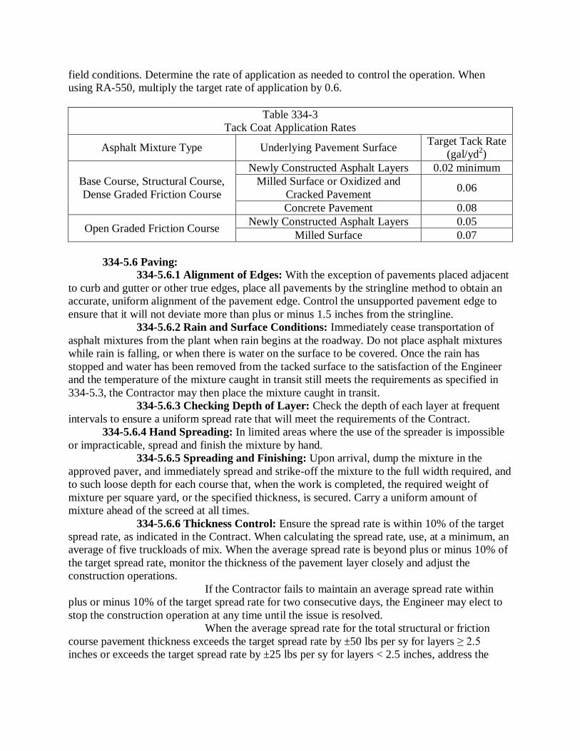
field conditions. Determine the rate of application as needed to control the operation. When using RA-550, multiply the target rate of application by 0.6.
Table 334-3 Tack Coat Application Rates
Asphalt Mixture Type Underlying Pavement Surface Target Tack Rate (gal/yd2)
Base Course, Structural Course, Dense Graded Friction Course
Newly Constructed Asphalt Layers 0.02 minimum Milled Surface or Oxidized and
Cracked Pavement 0.06
Concrete Pavement 0.08
Open Graded Friction Course Newly Constructed Asphalt Layers 0.05 Milled Surface 0.07
334-5.6 Paving: 334-5.6.1 Alignment of Edges: With the exception of pavements placed adjacent to curb and gutter or other true edges, place all pavements by the stringline method to obtain an accurate, uniform alignment of the pavement edge. Control the unsupported pavement edge to ensure that it will not deviate more than plus or minus 1.5 inches from the stringline. 334-5.6.2 Rain and Surface Conditions: Immediately cease transportation of asphalt mixtures from the plant when rain begins at the roadway. Do not place asphalt mixtures while rain is falling, or when there is water on the surface to be covered. Once the rain has stopped and water has been removed from the tacked surface to the satisfaction of the Engineer and the temperature of the mixture caught in transit still meets the requirements as specified in 334-5.3, the Contractor may then place the mixture caught in transit. 334-5.6.3 Checking Depth of Layer: Check the depth of each layer at frequent intervals to ensure a uniform spread rate that will meet the requirements of the Contract. 334-5.6.4 Hand Spreading: In limited areas where the use of the spreader is impossible or impracticable, spread and finish the mixture by hand. 334-5.6.5 Spreading and Finishing: Upon arrival, dump the mixture in the approved paver, and immediately spread and strike-off the mixture to the full width required, and to such loose depth for each course that, when the work is completed, the required weight of mixture per square yard, or the specified thickness, is secured. Carry a uniform amount of mixture ahead of the screed at all times. 334-5.6.6 Thickness Control: Ensure the spread rate is within 10% of the target spread rate, as indicated in the Contract. When calculating the spread rate, use, at a minimum, an average of five truckloads of mix. When the average spread rate is beyond plus or minus 10% of the target spread rate, monitor the thickness of the pavement layer closely and adjust the construction operations. If the Contractor fails to maintain an average spread rate within plus or minus 10% of the target spread rate for two consecutive days, the Engineer may elect to stop the construction operation at any time until the issue is resolved. When the average spread rate for the total structural or friction course pavement thickness exceeds the target spread rate by ±50 lbs per sy for layers ≥ 2.5 inches or exceeds the target spread rate by ±25 lbs per sy for layers < 2.5 inches, address the

unacceptable pavement in accordance with 334-5.10.4, unless an alternative approach is agreed upon by the Engineer. 334-5.7 Leveling Courses: 334-5.7.1 Patching Depressions: Before spreading any leveling course, fill all depressions in the existing surface as shown in the plans. 334-5.7.2 Spreading Leveling Courses: Place all courses of leveling with an asphalt paver or by the use of two motor graders, one being equipped with a spreader box. Other types of leveling devices may be used upon approval by the Engineer. 334-5.7.3 Rate of Application: When using Type SP-9.5 (fine graded) for leveling, do not allow the average spread of a layer to be less than 50 pounds per square yard or more than 75 pounds per square yard. The quantity of mix for leveling shown in the plans represents the average for the entire project; however, the Contractor may vary the rate of application throughout the project as directed by the Engineer. When leveling in connection with base widening, the Engineer may require placing all the leveling mix prior to the widening operation. 334-5.8 Compaction: For each paving or leveling train in operation, furnish a separate set of rollers, with their operators. When density testing for acceptance is required, select equipment, sequence, and coverage of rolling to meet the specified density requirement. Regardless of the rolling procedure used, complete the final rolling before the surface temperature of the pavement drops to the extent that effective compaction may not be achieved or the rollers begin to damage the pavement. When density testing for acceptance is not required, use a rolling pattern approved by the Engineer. Use hand tamps or other satisfactory means to compact areas which are inaccessible to a roller, such as areas adjacent to curbs, headers, gutters, bridges, manholes, etc. 334-5.9 Joints. 334-5.9.1 Transverse Joints: Construct smooth transverse joints, which are within 3/16 inch of a true longitudinal profile when measured with a 15 foot manual straightedge. These requirements are waived for transverse joints at the beginning and end of the project and at the beginning and end of bridge structures, if the deficiencies are caused by factors beyond the control of the Contractor such as no milling requirement, as determined by the Engineer. When smoothness requirements are waived, construct a reasonably smooth transitional joint. 334-5.9.2 Longitudinal Joints: For all layers of pavement except the leveling course, place each layer so that longitudinal construction joints are offset 6 to 12 inches laterally between successive layers. Do not construct longitudinal joints in the wheel paths. The Engineer may waive these requirements where offsetting is not feasible due to the sequence of construction. 334-5.10 Surface Requirements: Construct a smooth pavement with good surface texture and the proper cross slope.
334-5.10.1 Texture of the Finished Surface of Paving Layers: Produce a finished surface of uniform texture and compaction with no pulled, torn, raveled, crushed or loosened portions and free of segregation, bleeding, flushing, sand streaks, sand spots, or ripples. Correct any area of the surface that does not meet the foregoing requirements in accordance with 334-5.10.4.
334-5.10.2 Cross Slope: Construct a pavement surface with cross slopes in compliance with the requirements of the Contract Documents. 334-5.10.3 Pavement Smoothness: Construct a smooth pavement meeting the requirements of this Specification. Furnish a 15 foot manual and a 15 foot rolling straightedge meeting the requirements of FM 5-509. 334-5.10.3.1 Straightedge Testing: 334-5.10.3.1.1 Acceptance Testing: Using a rolling straightedge, test the final (top) layer of the pavement. Test all pavement lanes where the width is constant using a rolling straightedge and document all deficiencies on a form approved by the Engineer. Notify the Engineer of the location and time of all straightedge testing a minimum of 48 hours before beginning testing.
334-5.10.3.1.2 Final (Top) Pavement Layer: At the completion of all paving operations, straightedge the final (top) layer either behind the final roller of the paving train or as a separate operation. Address all deficiencies in excess of 3/16 inch in accordance with 334-5.10.4, unless waived by the Engineer. Retest all corrected areas.
334-5.10.3.1.3 Straightedge Exceptions: Straightedge testing will not be required in the following areas: shoulders, intersections, tapers, crossovers, sidewalks, bicycle/shared use paths, parking lots and similar areas, or in the following areas when they are less than 250 feet in length: turn lanes, acceleration/deceleration lanes and side streets. In the event the Engineer identifies a surface irregularity in the above areas that is determined to be objectionable, straightedge and address all deficiencies in excess of 3/8 inch in accordance with 334-5.10.4.
334-5.10.4 Correcting Unacceptable Pavement: Correct deficiencies in the pavement layer by removing and replacing the full depth of the layer, extending a minimum of 50 feet on both sides of the defective area for the full width of the paving lane, at no additional cost.
334-6 Acceptance of the Mixture. 334-6.1 General: The asphalt mixture will be accepted based on the Asphalt Work Category as defined below: 1. Asphalt Work Category 1 – Certification by the Contractor as defined in 334-6.2. 2. Asphalt Work Category 2 – Certification and process control testing by the Contractor as defined in 334-6.3 3. Asphalt Work Category 3 – Process control testing by the Contractor and acceptance testing by the Engineer as defined in 334-6.4. 334-6.2 Certification by the Contractor: On Asphalt Work Category 1 construction, the Engineer will accept the mix on the basis of visual inspection. Submit a Notarized Certification of Specification Compliance letter on company letterhead to the Engineer stating that all material produced and placed on the project meets the requirements of the Specifications. The Engineer may run independent tests to determine the acceptability of the material. 334-6.3 Certification and Process Control Testing by the Contractor: On Asphalt Work Category 2 construction, submit a Notarized Certification of Specification Compliance letter on company letterhead to the Engineer stating that all material produced and placed on the project meets the requirements of the Specifications, along with supporting test data documenting all process control testing as described in 334-6.3.1. If required by the Contract, utilize an Independent Laboratory as approved by the Engineer for the process control testing.

The mix will also require visual acceptance by the Engineer. In addition, the Engineer may run independent tests to determine the acceptability of the material. Material failing to meet these acceptance criteria will be addressed as directed by the Engineer such as but not limited to acceptance at reduced pay, delineation testing to determine the limits of the questionable material, removal and replacement at no cost to the agency, or performing an Engineering analysis to determine the final disposition of the material. . 334-6.3.1 Process Control Sampling and Testing Requirements: Perform process control testing at a frequency of once per day. Obtain the samples in accordance with FDOT Method FM 1-T 168. Test the mixture at the plant for gradation (P-8 and P-200) and asphalt binder content (Pb). Measure the roadway density with 6 inch diameter roadway cores at a minimum frequency of once per 1,500 feet of pavement with a minimum of three cores per day. Determine the asphalt binder content of the mixture in accordance with FM 5-563. Determine the gradation of the recovered aggregate in accordance with FM 1-T 030. Determine the roadway density in accordance with FM 1-T 166. The minimum roadway density will be based on the percent of the maximum specific gravity (Gmm) from the approved mix design. If the Contractor or Engineer suspects that the mix design Gmm is no longer representative of the asphalt mixture being produced, then a new Gmm value will be determined from plant-produced mix with the approval of the Engineer. Roadway density testing will not be required in certain situations as described in 334-6.4.1. Assure that the asphalt binder content, gradation and density test results meet the criteria in Table 334-4.
Table 334-4 Process Control and Acceptance Values
Characteristic Tolerance Asphalt Binder Content (percent) Target ± 0.55
Passing No. 8 Sieve (percent) Target ± 6.00 Passing No. 200 Sieve (percent) Target ± 2.00
Roadway Density (daily average) Minimum 91.5% of Gmm Roadway Density (any single core) Minimum 88.0 % of Gmm
334-6.4 Process Control Testing by the Contractor and Acceptance Testing by the Engineer: On Asphalt Work Category 3, perform process control testing as described in 334-6.3.1. In addition, the Engineer will accept the mixture at the plant with respect to gradation (P-8 and P-200) and asphalt binder content (Pb). The mixture will be accepted on the roadway with respect to density. The Engineer will sample and test the material as described in 334-6.3.1. The Engineer will randomly obtain at least one set of samples per day. Assure that the asphalt content, gradation and density test results meet the criteria in Table 334-4. Material failing to meet these acceptance criteria will be addressed as directed by the Engineer such as but not limited to acceptance at reduced pay, delineation testing to determine the limits of the questionable material, removal and replacement at no cost to the agency, or performing an Engineering analysis to determine the final disposition of the material. 334-6.4.1 Acceptance Testing Exceptions: When the total quantity of any mix type in the project is less than 500 tons, the Engineer will accept the mix on the basis of visual inspection. The Engineer may run independent tests to determine the acceptability of the material. Density testing for acceptance will not be performed on widening strips or

shoulders with a width of 5 feet or less, variable thickness overbuild courses, leveling courses, any asphalt layer placed on subgrade (regardless of type), miscellaneous asphalt pavement, bike/shared use paths, crossovers, or any course with a specified thickness less than 1 inch or a specified spread rate less than 100 lb per square yard. Density testing for acceptance will not be performed on asphalt courses placed on bridge decks or approach slabs. In addition, density testing for acceptance will not be performed on the following areas when they are less than 1,000 feet continuous in length: turning lanes, acceleration lanes, deceleration lanes, shoulders, parallel parking lanes, or ramps. Density testing for acceptance will not be performed in intersections. The limits of the intersection will be from stop bar to stop bar for both the mainline and side streets. Compact these courses in accordance with a standard rolling procedure approved by the Engineer. In the event that the rolling procedure deviates from the approved procedure, placement of the mix will be stopped.
334-7 Method of Measurement. For the work specified under this Section, the quantity to be paid for will be the weight of the mixture, in tons. The bid price for the asphalt mix will include the cost of the liquid asphalt or the asphalt recycling agent and the tack coat application as specified in 334-5.5.4. There will be no separate payment or unit price adjustment for the asphalt binder material in the asphalt mix.
334-8 Basis of Payment. 334-8.1 General: Price and payment will be full compensation for all the work specified under this Section.

SECTION 710PAINTED PAVEMENT MARKINGS
710-1 Description. Apply Painted Traffic Stripes and Markings, in accordance with the Contract Documents.
710-2 Materials. Use only materials listed on the Department’s Qualified Products List (QPL) meeting the
following requirements: Raised Retroreflective Pavement Markers and BituminousAdhesive .............................................................Section 970 Standard Waterborne Fast Dry Traffic Paint ..................................................................... 971-1 and 971-3 Fast Dry Solvent Paint ................................ 971-1 and 971-4 Glass Spheres .............................................. 971-1 and 971-2 The Engineer will take random samples of all material in accordance with the
Department’s Sampling, Testing and Reporting Guide schedule.
710-3 Equipment. Use equipment that will produce continuous uniform dimensions of pavement markings of varying widths and meet the following requirements: (a) Capable of traveling at a uniform, predetermined rate of speed, both uphill and downhill, in order to produce a uniform application of paint and capable of following straight lines and making normal curves in a true arc. (b) Capable of applying glass spheres to the surface of the completed stripe by an automatic sphere dispenser attached to the striping machine such that the glass spheres are dispensed closely behind the installed line. Use a glass spheres dispenser equipped with an automatic cut-off control that is synchronized with the cut-off of the traffic paint and applies the glass spheres in a manner such that the spheres appear uniform on the entire pavement markings surface with, 50 to 60% embedment. (c) Capable of spraying the paint to the required thickness and width without thinning of the paint. Equip the paint tank with nozzles equipped with cut-off valves, which will apply broken or skip lines automatically.
710-4 Application: 710-4.1 General: Remove existing pavement markings, such that scars or traces of removed markings will not conflict with new pavement markings, by a method approved by the Engineer. Payment for marking removal will be in accordance with 102-5.8. Before applying traffic stripes and markings, remove any material by a method approved by the Engineer that would adversely affect the bond of the traffic stripes. Apply traffic stripes and markings only to dry surfaces, and when the ambient air and surface temperature is at least 40ºF and rising. Do not apply traffic stripes and markings when winds are sufficient to cause spray dust. Apply traffic stripes and markings, having well defined edges, over existing pavement markings such that not more than 2 inches on either end and not more than 1 inch on either side is visible.
922

Mix the paint thoroughly prior to pouring into the painting machine. Apply paint to the pavement by spray or other means approved by the Engineer. Conduct field testing in accordance with FM 5-541. Remove and replace traffic stripes and markings not meeting the requirements of this Section at no additional cost to the Department. Apply all pavement markings prior to opening the road to traffic. 710-4.1.1 Final Surface: Painted pavement markings (final surface) will include two applications of standard painted pavement markings and one application of retroreflective pavement markers applied to the final surface. Wait at least 14 days after the first application to apply the second application of painted pavement markings (final surface). Second application must be applied prior to final acceptance of the project.
Apply all retroreflective pavement markers per the requirements of Section 706. 710-4.2 Thickness: Apply paint to attain a minimum wet film thickness in accordance with the manufacturer’s recommendations. 710-4.3 Retroreflectivity: Apply white and yellow standard pavement markings that will attain an initial retroreflectance of not less than 300 mcd/lx·m2 and not less than 250 mcd/lx·m2
The Department reserves the right to test the markings within 3 days of receipt of the Contractor’s certification. Failure to afford the Department opportunity to test the markings will result in non-payment. The test readings should be representative of the Contractor’s striping performance. If the retroreflectivity values measure below values shown above, reapply the striping at no additional cost to the Department.
, respectively. Measure, record and certify on a Department approved form and submit to the Engineer, the retroreflectivity of white and yellow pavement markings in accordance with FM 5-541.
For standard pavement markings, ensure that the minimum retroreflectance of white and yellow pavement markings are not less than 150 mcd/lx m2. If the retroreflectivity values fall below the 150 mcd/lx m2
710-4.4 Color: Use paint material that meets the requirements of 971-1.
value within six months of initial application, the striping will be reapplied at the Contractor’s expense.
710-4.5 Glass Spheres: Apply glass spheres on all pavement markings immediately and uniformly following the paint application. The rate of application shall be based on the manufacturer’s recommendation.
710-5 Tolerances in Dimensions and in Alignment. Establish tack points at appropriate intervals for use in aligning stripes, and set a stringline from such points to achieve accuracy. 710-5.1 Dimensions: 710-5.1.1 Longitudinal Lines: Apply painted skip line segments with no more than plus or minus 12 inches variance, so that over-tolerance and under-tolerance lengths between skip line and the gap will approximately balance. Apply longitudinal lines at least 2 inches from construction joints of portland cement concrete pavement.
710-5.1.2 Transverse Markings, Gore Markings, Arrows, and Messages: Apply paint in multiple passes when the marking cannot be completed in one pass, with an overall line width allowable tolerance of plus or minus 1 inch.
923

710-5.1.3 Contrast Lines: Use black paint to provide contrast on concrete or light asphalt pavement, when specified by the Engineer. Apply black paint in 10 foot segments following each longitudinal skip line. 710-5.2 Alignment: Apply painted stripes that will not deviate more than 1 inch from the stringline on tangents and curves one degree or less. Apply painted stripes that will not deviate more than 2 inches from the stringline on curves greater than one degree. Apply painted edge stripes uniformly, not less than 2 inches or more than 4 inches from the edge of pavement, without noticeable breaks or deviations in alignment or width. Remove and replace at no additional cost to the Department, traffic stripes that deviate more than the above stated requirements. 710-5.3 Correction Rates: Make corrections of variations in width at a maximum rate of 10 feet for each 0.5 inches of correction. Make corrections of variations in alignment at a maximum rate of 25 feet for each 1 inch of correction, to return to the stringline.
710-6 Contractor’s Responsibility for Notification. Notify the Engineer prior to the placement of the materials. Furnish the Engineer with the manufacturer’s name and batch numbers of the materials and glass spheres to be used. Ensure that the approved batch numbers appear on the materials and glass spheres packages.
710-7 Protection of Newly Painted Pavement Markings. Do not allow traffic onto or permit vehicles to cross newly applied pavement markings until they are sufficiently dry. Remove and replace any portion of the pavement markings damaged by passing traffic or from any other cause, at no additional cost to the Department.
710-8 Corrections for Deficiencies to Applied Painted Pavement Markings. Reapply a 1.0 mile section centered around any deficiency, at no additional cost to the Department.
710-9 Submittals. 710-9.1 Submittal Instructions: Prepare a certification of quantities, using the Department’s current approved form, for each project in the Contract. Submit the certification of quantities and daily worksheets to the Engineer. The Department will not pay for any disputed items until the Engineer approves the certification of quantities. 710-9.2 Contractor’s Certification of Quantities: Request payment by submitting a certification of quantities no later than Twelve O’clock noon Monday after the estimate cut-off date or as directed by the Engineer, based on the amount of work done or completed. Ensure the certification of quantities consists of the following: (a) Contract Number, FPID Number, Certification Number, Certification Date and the period that the certification represents. (b) The basis for arriving at the amount of the progress certification, less payments previously made and less any amount previously retained or withheld. The basis will include a detailed breakdown provided on the certification of items of payment.
710-10 Method of Measurement. The quantities to be paid for under this Section will be as follows: (a) The length, in net miles, of 6 inch solid traffic stripe, authorized and acceptably applied.
924

(b) The total traversed distance in gross miles of 10-30 or 3-9 skip line. The actual applied line is 25% of the traverse distance for a 1:3 ratio. This equates to 1,320 feet of marking per mile of single line. (c) The net length, in feet, of each of all other types of lines and stripes, authorized and acceptably applied. (d) The number of pavement messages, symbols and directional arrows, authorized and acceptably applied. (e) Lump Sum, as specified in 710-4.1.1 when the item for painted pavement markings (final surface) is included in the proposal. The net length, in feet of dotted and skip stripes other than 10-30 and 3-9 will be measured as the distance from the beginning of the first painted stripe to the end of the last painted stripe with proper deductions made for unpainted intervals as determined by plan dimensions or stations, subject to 9-1.3. Unpainted intervals will not be included in pay quantity. The gross-mile measurement of 10-30 and 3-9 skip traffic stripes will be taken as the distance from the beginning of the first painted stripe to the end of the last painted stripe, and will include the unpainted intervals. It will not include any lengths of unpainted intervals which, by design or by other intent of the Department, are greater than 30 feet. Final measurement will be determined by plan dimensions or stations, subject to 9-1.3.1.
710-11 Basis of Payment. 710-11.1 General: Prices and payments will be full compensation for all work specified in this Section, including, all cleaning and preparing of surfaces, furnishing of all materials, application, curing and protection of all items, protection of traffic, furnishing of all tools, machines and equipment, and all incidentals necessary to complete the work. Final payment will be withheld until all deficiencies are corrected. 710-11.2 Lump Sum Payment: When the item for painted pavement markings (final surface) is included in the proposal, prices and payments will be full compensation for two applications of all painted pavement markings applied to the final surface, and one application of retroreflective pavement markers applied to the final surface in accordance with Section 706. Payment will be made under:
Item No. 710 Painted Pavement Markings. Traffic Stripes, Solid - per net mile. Traffic Stripes, Solid - per foot.
Traffic Stripes, Skip - per gross mile. Traffic Stripes, Skip - per foot. Dotted/Guideline - per foot.
Messages -each. Arrows - each. Yield Markings - per foot. Item No. 710-90 Painted Pavement Markings (Final Surface) - lump sum.
925
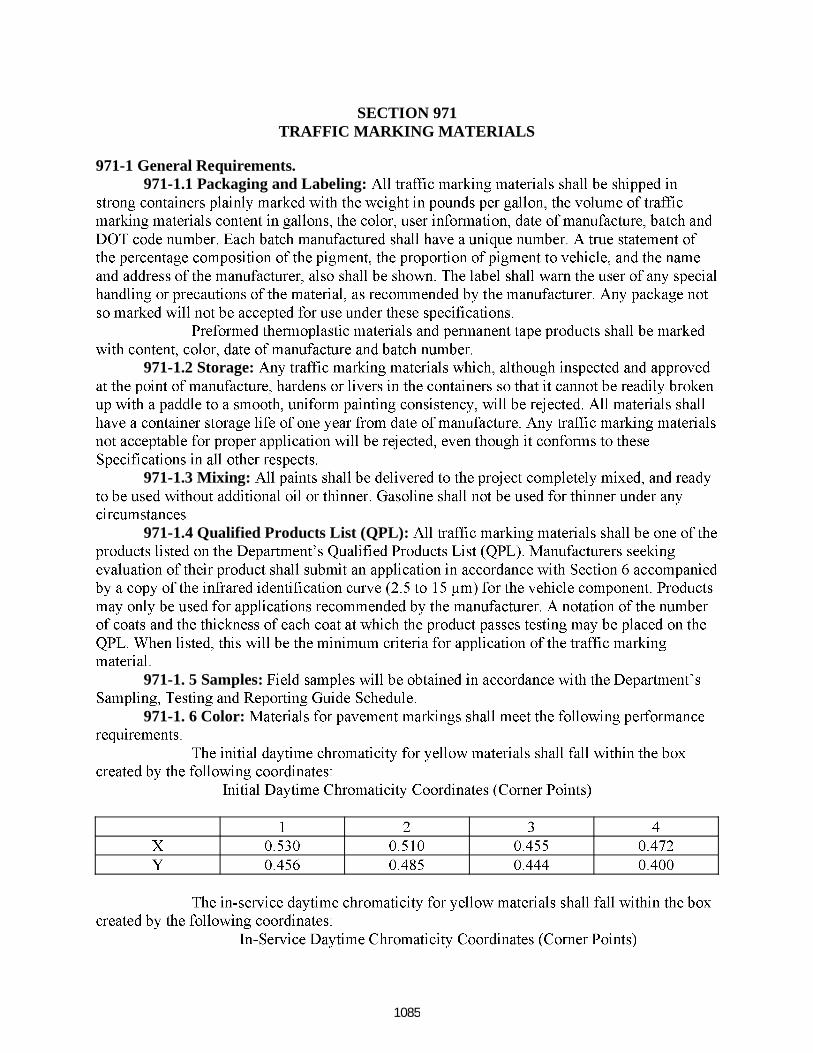
SECTION 971TRAFFIC MARKING MATERIALS
971-1 General Requirements.971-1.1 Packaging and Labeling:
971-1.2 Storage:
971-1.3 Mixing:
971-1.4 Qualified Products List (QPL):
971-1. 5 Samples:
971-1. 6 Color:
1085

971-1.7 Additional Requirements:
971-2 Glass Spheres.971-2.1 General Requirements:
971-2.2 Specific Properties
1086

971-2.3 Sampling: 971-2.3.1 Sampling:
971-2.3.2 Containers:
971-3 Standard Waterborne Fast Dry Traffic Paint. 971-3.1 General:
971-3.2 Composition:
1087
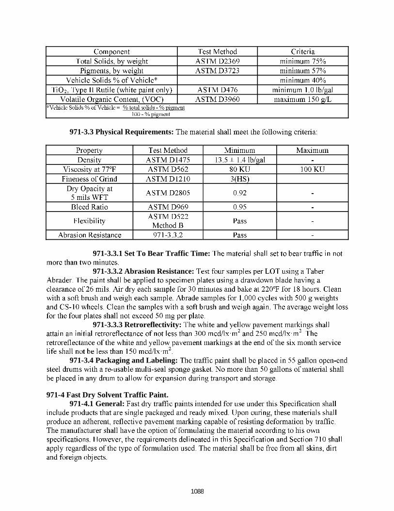
971-3.3 Physical Requirements:
971-3.3.1 Set To Bear Traffic Time:
971-3.3.2 Abrasion Resistance:
971-3.3.3 Retroreflectivity:
971-3.4 Packaging and Labeling:
971-4 Fast Dry Solvent Traffic Paint.971-4.1 General:
1088
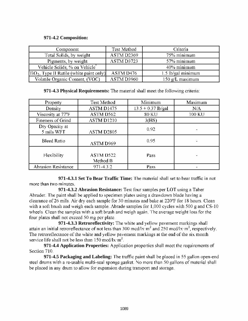
971-4.2 Composition:
971-4.3 Physical Requirements:
971-4.3.1 Set To Bear Traffic Time:
971-4.3.2 Abrasion Resistance:
971-4.3.3 Retroreflectivity:
971-4.4 Application Properties:
971-4.5 Packaging and Labeling:
1089
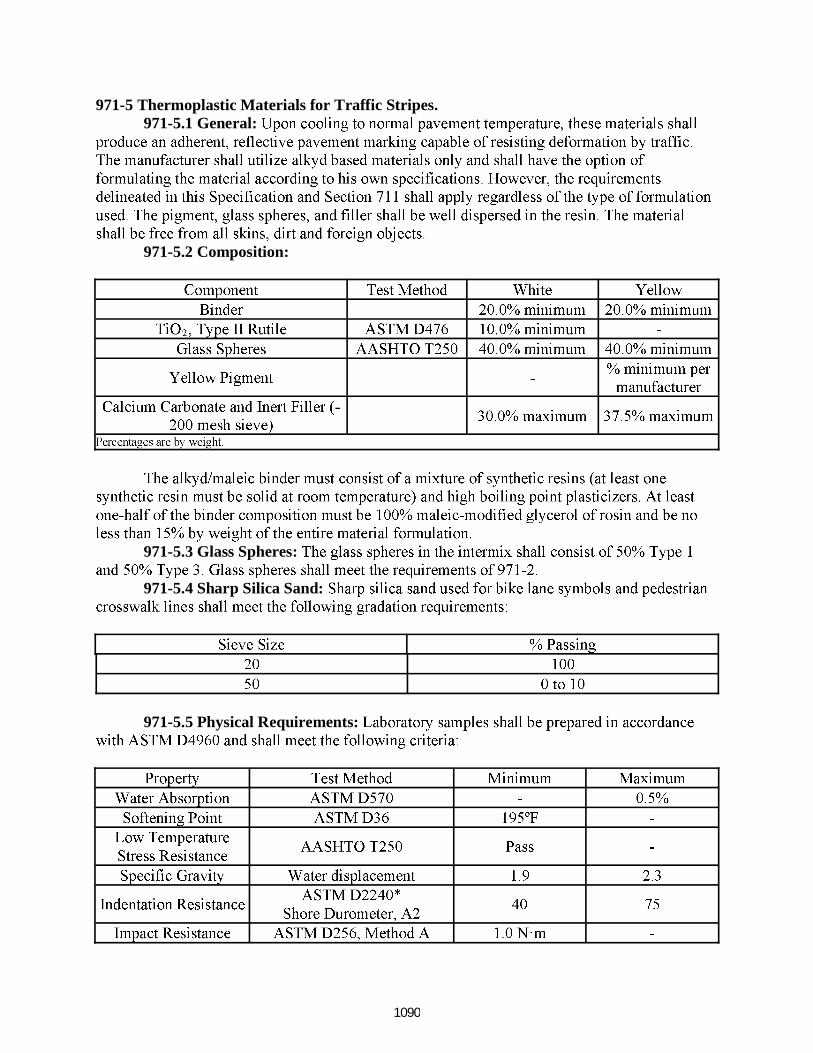
971-5 Thermoplastic Materials for Traffic Stripes.971-5.1 General:
971-5.2 Composition:
971-5.3 Glass Spheres:
971-5.4 Sharp Silica Sand:
971-5.5 Physical Requirements:
1090

971-5.5.1 Set To Bear Traffic Time:
971-5.5.2 Retroreflectivity:
971-5.5.3 Durability:
971-5.6 Application Properties:
971-5.7 Packing and Labeling:
971-6 Preformed Thermoplastic Materials for Traffic Stripes.971-6.1 General:
971-6.2 Composition:
971-6.3 Glass Spheres: 971-6.4 Color:
971-6.5 Physical Requirements:
1091

971-6.5.1 Retroreflectivity:
971-6.5.2 Skid Resistance:
971-6.5.3 Durability:
971-6.6 Application Properties:
971-6.7 Packing and Labeling:
971-7 Permanent Tape Materials for Traffic Stripes and Markings.971-7.1 General:
971-7.2 Composition:
971-7.3 Skid Resistance:
971-7.4 Thickness:971-7.5 Durability and Wear Resistance:
971-7.6 Conformability and Resealing:
1092
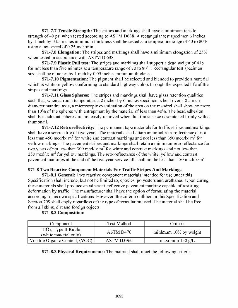
971-7.7 Tensile Strength:
971-7.8 Elongation:
971-7.9 Plastic Pull test:
971-7.10 Pigmentation:
971-7.11 Glass Spheres:
971-7.12 Retroreflectivity:
971-8 Two Reactive Component Materials For Traffic Stripes And Markings.971-8.1 General:
971-8.2 Composition:
971-8.3 Physical Requirements:
1093

971-8.3.1 Set To Bear Traffic Time:
971-8.3.2 Abrasion Resistance:
971-8.3.3 Retroreflectivity:
971-8.4 Application Properties:
971-8.5 Packaging and Labeling:
971-9 Thermoplastic Material for Audible and Vibratory Traffic Stripes. 971-9.1 General:
971-9.2 Composition:
1094

971-9.3 Retroreflective Elements:
971-9.4 Physical Requirements:
971-9.4.1 Set To Bear Traffic Time:
971-9.4.2 Retroreflectivity:
971-9.4.3 Durability:
971-9.5 Application Properties:
971-9.6 Packing and Labeling:
1095
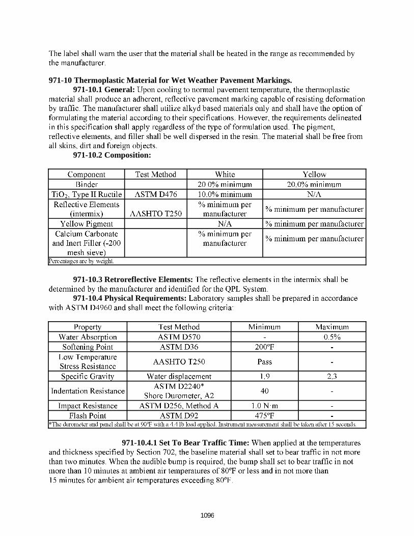
971-10 Thermoplastic Material for Wet Weather Pavement Markings. 971-10.1 General:
971-10.2 Composition:
971-10.3 Retroreflective Elements:
971-10.4 Physical Requirements:
971-10.4.1 Set To Bear Traffic Time:
1096

971-10.4.2 Retroreflectivity:
971-10.4.3 Durability:
971-10.5 Application Properties:
971-10.6 Packing and Labeling:
1097

RFP #2015C-01 Title: Asphalt Pavement & Sidewalk Delivery Order Contracting Services Page 94 of 180
Florida State College at Jacksonville does not discriminate against any person on the basis of race, color, ethnicity, genetic information, national origin, religion, gender, marital status, disability, or age in its programs or activities. Inquiries regarding the non-discrimination policies may be
directed to the College’s Equity Officer, 501 West State Street, Jacksonville, Florida 32202| (904) 632-3221 or [email protected].
Florida State College at Jacksonville is a member of the Florida College System and is not affiliated with any other public or private university or college in Florida or elsewhere.