appendix a chapter 129 and chapter 132: volatile …€¦ · chapter 129 and . chapter 132 ....
TRANSCRIPT

1
APPENDIX A
CHAPTER 129 and CHAPTER 132
VOLATILE ORGANIC COMPOUNDS TEST METHODS AND COMPLIANCE PROCEDURES
Procedure A Test methods and Compliance Procedures: General Provisions Procedure B Determining the Volatile Organic Compound (VOC) content of Coatings and Inks Procedure C Alternative Compliance Methods for Surface Coating of Cans, Fabric, Vinyl,
Miscellaneous Metal Products, Metal Furniture, Flatwood Paneling and Graphic Arts
Procedure D Repealed Procedure E Emission Capture and Destruction or Removal Efficiency and Monitoring
Requirements Procedure F Determining the Destruction or Removal Efficiency of a Control Device Procedure G Leak Detection Methods for Volatile Organic Compounds (VOC) Procedure H Performance Specifications for Continuous Emissions Monitoring of Total
Hydrocarbons Procedure I Quality Control Procedures for VOC Continuous Emission Monitoring Systems

2
VOLATILE ORGANIC COMPOUNDS PROCEDURE A
Test Methods and Compliance Procedures: General Provisions.
(a) Test methods. The owner or operator of any volatile organic compound (VOC) source required to comply with Chapters 129 and 132 shall, at the owner's or operator's expense, demonstrate compliance by using the methods of Procedures A-C and E-H of this subpart or alternative methods that are approved by the Department and EPA as part of a State Implementation Plan (SIP) revision and shall meet all the requirements of these regulations. (b) Preparation of test plan and quality assurance program. At least 30 days before the initiation of a required test the owner or operator shall submit a test plan that shall be approved by the Department before the results of the test are considered acceptable. This test plan shall include the following minimum information: (1) The purpose of the proposed test and the applicable regulation; (2) A detailed description of the facility to be tested, including a line diagram of the facility,
locations of test sites, and facility operation conditions for the test; (3) A detailed description of the proposed test methods and procedures, equipment, and
sampling sites;
(4) A time table for the following:
(i) Date for the compliance test;
(ii) Date for submittal of final test report to the Department (not later than 45 days after completion of on-site sampling);
(5) Proposed corrective actions should the test results show noncompliance;
(6) Internal QA program. The internal quality assurance (QA) program shall include, at a minimum, the activities planned by routine operators and analysts to provide an assessment of test data precision. An example of internal QA is the sampling and analysis of replicable samples; and
(7) External QA program.
(i) The external QA program shall include, at a minimum, application of plans for a test method performance audit (PA) during the compliance test.
(ii) The external QA program may also include systems audits, which include the opportunity for on-site evaluation by the Department of instrument calibration, data validation, sample logging, and documentation of quality control data and field maintenance activities. (iii) The PA shall consist of blind audit samples provided by the Department and analyzed during the compliance test to provide a measure of test data bias.

3
(A) The Department shall require the owner or operator to analyze PA
samples during each compliance test when audit samples are available. (B) Information concerning the availability of audit materials for a specific
compliance test may be obtained by contacting the Emission Measurement Technical Information Center at (919) 541-2237.
(C) If the Department has prior knowledge that an audit material is available,
the Department may contact the Atmospheric Research and Exposure Assessment Laboratory directly at (919) 541-4531 (for cylinder gas audit materials) or (919) 541-7834 (for all other types of audit materials).
(D) The evaluation criteria applied to the interpretation of the PA results and the subsequent remedial actions required of the owner or operator are the sole responsibility of the Department.
(c) Process operation. The owner or operator shall be responsible for providing: (1) Sampling ports, pipes, lines, or appurtenances for collecting samples and data required
by the test methods and procedures; (2) Safe access to the sample and data collection locations; and (3) Light, electricity, and the utilities required for sample and data collection. (d) Final report. No later than 45 days after completion of the on-site sampling, the owner or operator shall submit a test report to the Department. The test report shall include the following minimum information: (1) Process description; (2) Air pollution capture system and control device description; (3) Process conditions during testing; (4) Test results and example calculations; (5) Description of sampling locations and test methods; (6) Quality assurance measures; and (7) Field and analytical data.
4
VOLATILE ORGANIC COMPOUNDS PROCEDURE B
Test Methods and Compliance Procedures: Determining the Volatile Organic Compound (VOC)
Content of Coatings and Inks (a) Sampling procedures shall follow the guidelines presented in "Standard Procedure for Collection of Coating and Ink Samples for VOC Content Analysis by Reference Method 24 and Reference Method 24A," EPA-340/1-91-010. (b) The analytical methods and procedures specified below shall be used to determine the VOC content of each coating, as applied: (1) (i) Method 24 of 40 CFR Part 60, Appendix A, shall be used to determine total
volatile content, water content, and density of coatings. For determining total volatile content, all samples shall be oven-dried at 110°C for 1 hour.
(ii) To determine the total volatile content, water content, and density of
multicomponent coatings, the following procedures shall be used in addition to Method 24 of 40 CFR Part 60, Appendix A:
(A) The components shall be mixed in a storage container in the same
proportions as those in the coating, as applied. The mixing shall be accomplished by weighing the components in the proper proportion into a container that is closed between additions and during mixing. About 100 milliliters (ml) of coating shall be prepared in a container just large enough to hold the mixture prior to withdrawing a sample;
(B) For determining volatile content, a sample shall be withdrawn from the
mixed coating and then transferred to a dish where the sample shall stand for at least 1 hour, but no more than 24 hours, prior to being oven-dried at 110°C for 1 hour; and
(C) For determining the water content and density of multicomponent
coatings, samples shall be taken from the same 100-ml mixture of coating and shall be analyzed by the appropriate ASTM methods referenced in Method 24 of 40 CFR Part 60, Appendix A;
(2) Method 24 of 40 CFR Part 60, Appendix A, shall be used in determining total volatile
content, water content, and density of any flexographic or packaging rotogravure printing ink and related coatings. Alternatively, Method 24A of 40 CFR Part 60, Appendix A, may be used;
(3) Method 24A of 40 CFR Part 60, Appendix A, shall be used in determining total volatile
content, water content, and density of any publication rotogravure printing ink and related coatings; and
(4) The following additional procedure shall be used in analyzing a coating sample:
"Standard Procedure for Analysis of Coating and Ink Samples," EPA-340/1-91-011.
5
(c) Use of adaptations to test methods. Use of an adaptation to any of the analytical methods specified in paragraph (b) of this section shall be approved by the Department and EPA on a case-by-case basis. An owner or operator shall submit sufficient documentation for the Department to find that the analytical methods specified in paragraphs (b)(1), (b)(2), and (b)(3) will yield inaccurate results and that the proposed adaptation is appropriate. (d) Each sample collected for analysis shall meet the following criteria: (1) Each sample shall be at least 250 ml (8 ounces [oz]) taken into a 250-ml (8-oz) container
at a location and time such that the sample will be representative of the coating or ink, as applied (i.e., the sample shall include any dilution solvent or VOC added during the manufacturing process);
(2) If a sample larger than 250 ml (8 oz) is obtained, the sample container shall be of a size
such that the sample completely fills the container; (3) The container shall be tightly sealed immediately after the sample is taken; (4) Any solvent or other VOC added after the sample is taken shall be measured and
accounted for in the calculations in paragraph (e) of this section; and (5) For multicomponent coatings, separate samples of each component shall be obtained. (e) Calculations for determining the VOC content of coatings and inks from data as determined by Method 24 or 24A of 40 CFR Part 60, Appendix A, shall follow the guidance provided in the following documents: (1) "A Guideline for Surface Coating Calculations," EPA-340/1-86-016; and (2) "Procedures for Certifying Quantity of Volatile Organic Compounds Emitted by Paint,
Ink and Other Coatings," (Revised June 1986) EPA-450/3-84-019.
6
VOLATILE ORGANIC COMPOUNDS
PROCEDURE C
Test Methods and Compliance Procedures: Alternative Compliance Methods for Surface Coating of Cans, Fabric, Vinyl, Metal Furniture and Miscellaneous Metal Products, Flatwood
Paneling and Graphic Arts (a) Daily-weighted average.
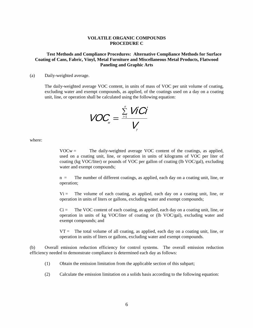
The daily-weighted average VOC content, in units of mass of VOC per unit volume of coating, excluding water and exempt compounds, as applied, of the coatings used on a day on a coating unit, line, or operation shall be calculated using the following equation:
VOCViCiVw
i
n
T
= =∑
1
where: VOCw = The daily-weighted average VOC content of the coatings, as applied,
used on a coating unit, line, or operation in units of kilograms of VOC per liter of coating (kg VOC/liter) or pounds of VOC per gallon of coating (lb VOC/gal), excluding water and exempt compounds;
n = The number of different coatings, as applied, each day on a coating unit, line, or
operation; Vi = The volume of each coating, as applied, each day on a coating unit, line, or
operation in units of liters or gallons, excluding water and exempt compounds; Ci = The VOC content of each coating, as applied, each day on a coating unit, line, or
operation in units of kg VOC/liter of coating or (lb VOC/gal), excluding water and exempt compounds; and
VT = The total volume of all coating, as applied, each day on a coating unit, line, or
operation in units of liters or gallons, excluding water and exempt compounds. (b) Overall emission reduction efficiency for control systems. The overall emission reduction efficiency needed to demonstrate compliance is determined each day as follows: (1) Obtain the emission limitation from the applicable section of this subpart; (2) Calculate the emission limitation on a solids basis according to the following equation:

7
S CCd
=−1 ( )
where: S = The VOC emission limitation in terms of kg VOC/liter of coating solids or (lb
VOC/gal); C = The VOC emission limitation in terms of kg VOC/liter of coating or (lb/gal),
excluding water and exempt compounds; and d = The density of VOC for converting emission limitation to a solids basis. The
density equals 0.882 kg/liter (7.36 lb/gal); (3) Calculate the required overall emission reduction efficiency of the control system for the
day according to the following equation:
E VOCa SVOCa
x=−[ ( ) ] 100
where: E = The required overall emission reduction efficiency of the control system for the
day; VOCa = (1) The maximum VOC content of the coatings, as applied, used each
day on the subject coating unit, line, or operation, in units of kg VOC/liter of coating solids or (lb VOC/gal), as determined by the applicable test methods and procedures specified in Procedure B, or
(2) The daily-weighted average VOC content, as applied, of the
coatings used each day on the subject coating unit, line, or operation, in units of kg VOC/liter of coating solids or (lb VOC/gal), as determined by the applicable test methods and procedures specified in Procedure B and the procedure in paragraph (c)(4) of this section; and S = VOC emission limitation in terms of kg VOC/liter of coating solids or (lb VOC/gal); and
(4) The daily-weighted average VOC content, as applied, of the coatings used on a coating
unit, line, or operation in units of mass of VOC per unit volume of coating solids shall be calculated by the following equation:
VOCws
Wvoci Vi Di
V i VSii
n
i
n= =
=
∑
∑1
1
where:

8
VOCws = The daily-weighted average VOC content, as applied, of the coatings
used on a coating unit, line, or operation in units of mass of VOC per unit volume of coating solids;
n = The number of different coatings, as applied, used in a day on a coating unit,
line, or operation; Vi = The volume of each coating (i), as applied, used in a day on a coating unit, line,
or operation in units of liters or gallons; Wvoci = The weight fraction of VOC in each coating (i), as applied, used in a day
on a coating unit, line, or operation in units of kg VOC/kg coating or (lb/lb); Di = The density of each coating (i) as applied, used in a day on a coating unit, line,
or operation in units of kg coating/liter of coating or (lb/gal); and
VSi = The volume fraction solids content of each coating (i), as applied, used in a day on a coating unit, line, or operation in units of liters solids/liter coating or (gal/gal).
9
VOLATILE ORGANIC COMPOUNDS PROCEDURE E
Test Methods and Compliance Procedures: Emission Capture and Destruction or Removal
Efficiency and Monitoring Requirements. (a) Determining the efficiency of volatile organic compound (VOC) capture systems. (1) For purposes of this paragraph, the following definitions and abbreviations apply: "Gas/gas method" means either of two methods for determining capture that rely only on gas
phase measurements. One method requires construction of a temporary total enclosure (TTE) to ensure all potential fugitive emissions are measured while the other method uses the room or building that houses the source as an enclosure.
"Hood" means a partial enclosure or canopy for capturing and exhausting, by means of a draft,
the organic vapors or other fumes rising from a coating process or other source. "Liquid/gas method" means either of two methods for determining capture that require both gas
phase and liquid phase measurements and analysis. One liquid/gas method requires construction of a temporary enclosure, and the other uses the building or room that houses the facility as an enclosure.
"Process line" means any coating unit, coating line, coating operation, or printing press. "PTE" is a permanent total enclosure, which contains a process that emits VOC and meets the
specifications given in Chapter 126 Appendix A Procedure T. "TTE" is a temporary total enclosure that is built around a process that emits VOC and meets the
specifications given in Chapter 126 Appendix A Procedure T. "BE" is a building or room enclosure that contains a process that emits VOC. If a BE is to
substitute for a PTE or TTE, the appropriate requirements given in Chapter 126 Appendix A Procedure T shall be met.
(2) Applicability. (i) The requirements of paragraph (a)(3) shall apply to all regulated VOC emitting
processes using a control system except as provided below. (ii) If a source owner or operator installs a PTE that meets EPA specifications, and
that directs all VOC to a control device, the capture efficiency is assumed to be 100 percent, and the source is exempted from the requirements described in paragraph (a)(3). Chapter 126 Appendix A Procedure T shall be used to determine whether a structure is a PTE. This does not exempt a source from performing any control device efficiency testing required under this subpart. In addition, a source shall demonstrate that all criteria for a PTE are met during the testing for capture efficiency.
(iii) If a source owner or operator uses a control device designed to collect and
recover VOC (e.g., carbon adsorber), an explicit measurement of capture efficiency is

10
not necessary if the conditions given below are met. The overall emission reduction efficiency of the control system shall be determined each day by directly comparing the input liquid VOC (liters) to the recovered liquid VOC. The procedure for use in this situation is specified in 40 CFR 60.433 with the following modifications:
(A) The source owner or operator shall obtain data each day for the solvent
usage and solvent recovery and determine the solvent recovery efficiency of the system each day using a 7-day rolling period. The recovery efficiency for each day is computed as the ratio of the total recovered solvent for that day and the prior 6 consecutive operating days to the total solvent usage for the same 7-day period used for the recovered solvent, rather than a 30-day weighted average as given in 40 CFR 60.433. This ratio shall be expressed as a percentage. This shall be done within 72 hours following each 24-hour period, and
(B) If the solvent recovery system controls multiple process lines, the source
owner or operator shall demonstrate that the overall control (i.e., the total recovered solvent VOC divided by the sum of liquid VOC input to all process lines venting to the control system) meets or exceeds the most stringent standard applicable for any process line venting to the control system.
(3) Specific Requirements. (i) The capture efficiency shall be measured using one of the four protocols given in
paragraphs (a)(3)(iii)(A) through (a)(3)(iii)(D) of this section. During any capture efficiency test, the average face velocity of each emissions collection point ducted to the control device shall be measured and recorded. In addition, the distance between each collection point ducted to the control device and the emission source shall be measured and recorded. Measurements of average face velocity shall be done by determining average volumetric flow rate using Reference Method 2, 2A or 2C of 40 CFR Part 60, Appendix A and dividing by the total area of the face of the collection point.
(ii) Any error margin associated with a test protocol may not be incorporated into
the results of a capture efficiency test. (iii) Any source required to comply with this section shall use one of the following
protocols to measure capture efficiency, unless a suitable alternative protocol is approved by the Department and EPA:
(A) Gas/gas method using TTE. Chapter 126 Appendix A Procedure T shall
be used to determine whether a temporary enclosure is a TTE. The capture efficiency equation to be used for this protocol is:
CE GwGw Fw
=+
where:
11
CE = capture efficiency, decimal fraction; Gw = mass of VOC captured and delivered to control device using a TTE; and Fw = mass of fugitive VOC that escapes from a TTE. Chapter 126 Appendix A procedures are used to obtain Fw & Gw.
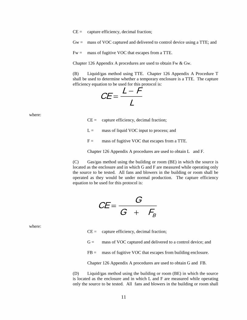
(B) Liquid/gas method using TTE. Chapter 126 Appendix A Procedure T shall be used to determine whether a temporary enclosure is a TTE. The capture efficiency equation to be used for this protocol is:
CE L F
L=
−
where: CE = capture efficiency, decimal fraction; L = mass of liquid VOC input to process; and F = mass of fugitive VOC that escapes from a TTE. Chapter 126 Appendix A procedures are used to obtain L and F. (C) Gas/gas method using the building or room (BE) in which the source is
located as the enclosure and in which G and F are measured while operating only the source to be tested. All fans and blowers in the building or room shall be operated as they would be under normal production. The capture efficiency equation to be used for this protocol is:
CE G
G FB
=+
where: CE = capture efficiency, decimal fraction; G = mass of VOC captured and delivered to a control device; and FB = mass of fugitive VOC that escapes from building enclosure. Chapter 126 Appendix A procedures are used to obtain G and FB. (D) Liquid/gas method using the building or room (BE) in which the source
is located as the enclosure and in which L and F are measured while operating only the source to be tested. All fans and blowers in the building or room shall

12
be operated as they would under normal production. The capture efficiency equation to be used for this protocol is:
CE L F
LB=
−
where: CE = capture efficiency, decimal fraction; L = mass of liquid VOC input to process; and FB = mass of fugitive VOC that escapes from building enclosure. Chapter 126 Appendix A procedures are used to obtain L and FB. (4) Recordkeeping and Reporting. (i) All sources complying with this section shall maintain on file a copy of the
capture efficiency protocol submitted to the Department. All results of appropriate test methods and CE protocols shall be reported to the Department within 60 days of the test date. A copy of the results shall be kept on file with the source.
(ii) If any changes are made to capture or control equipment, the source is required
to notify the Department in writing within 30 days of these changes and a new capture efficiency and/or control device destruction or removal efficiency test may be required. A change to the capture or control equipment shall be defined as any modification to or malfunction of the capture system or control system that increases the distance between any emissions collection point and the emissions source that the collection point is serving or that reduces the average face velocity at any emissions collection point ducted to the control device to a value less than 90% of the value measured and recorded during the capture efficiency test. Reduction in the air flow at a collection point that occurs because the emission source that the collection point is serving is not being utilized shall not be considered a change requiring Department notification. Measurements of average face velocity shall be done at all collection points whenever any physical changes are made to the capture system.
The source must notify the Department 30 days prior to performing any capture
efficiency and/or control efficiency tests. (b) Determining the destruction or removal efficiency of incinerators and carbon adsorbers. (1) Testing. (i) The control device destruction or removal efficiency shall be determined from
data obtained by simultaneously measuring the inlet and outlet gas-phase VOC concentrations and gas volumetric flow rates in accordance with the gas-phase test
13
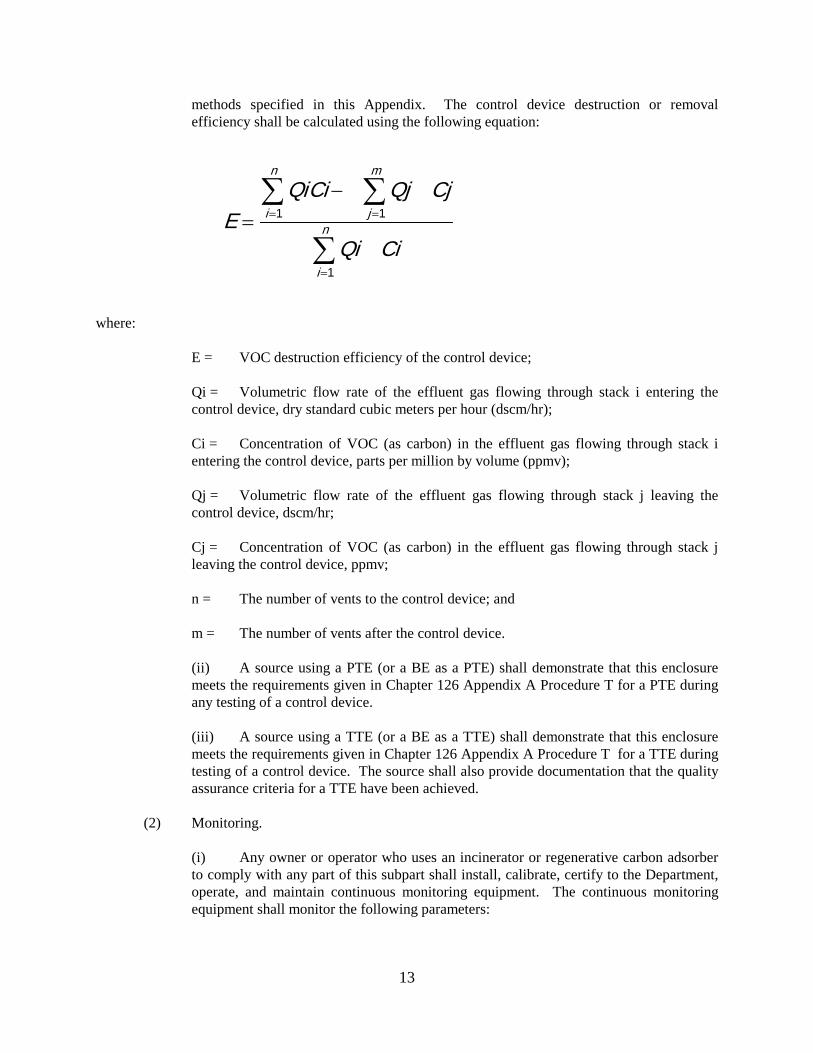
methods specified in this Appendix. The control device destruction or removal efficiency shall be calculated using the following equation:
E
QiCi Qj Cj
Qi Ci
j
m
i
n
i
n=−
==
=
∑∑
∑11
1
where: E = VOC destruction efficiency of the control device; Qi = Volumetric flow rate of the effluent gas flowing through stack i entering the
control device, dry standard cubic meters per hour (dscm/hr); Ci = Concentration of VOC (as carbon) in the effluent gas flowing through stack i
entering the control device, parts per million by volume (ppmv); Qj = Volumetric flow rate of the effluent gas flowing through stack j leaving the
control device, dscm/hr; Cj = Concentration of VOC (as carbon) in the effluent gas flowing through stack j
leaving the control device, ppmv; n = The number of vents to the control device; and m = The number of vents after the control device. (ii) A source using a PTE (or a BE as a PTE) shall demonstrate that this enclosure
meets the requirements given in Chapter 126 Appendix A Procedure T for a PTE during any testing of a control device.
(iii) A source using a TTE (or a BE as a TTE) shall demonstrate that this enclosure
meets the requirements given in Chapter 126 Appendix A Procedure T for a TTE during testing of a control device. The source shall also provide documentation that the quality assurance criteria for a TTE have been achieved.
(2) Monitoring. (i) Any owner or operator who uses an incinerator or regenerative carbon adsorber
to comply with any part of this subpart shall install, calibrate, certify to the Department, operate, and maintain continuous monitoring equipment. The continuous monitoring equipment shall monitor the following parameters:
14
(A) Combustion chamber temperature of each thermal incinerator or afterburner;
(B) Temperature rise immediately before the catalyst bed and across each
catalytic incinerator bed; and (C) The VOC concentration of the outlet from each carbon adsorption bed. (ii) The continuous temperature monitoring equipment must be equipped with a
continuous recorder and have an accuracy of ±1 percent of the combustion temperature being measured expressed in degrees Celsius (°C) or ±0.5°C, whichever is greater.
(iii) The owner or operator shall ensure that the quality assurance measures in �
Procedure H and the quality control procedures in Procedure F are met. (c) Determining the overall emission reduction efficiency. The overall emission reduction efficiency of the emission control system shall be determined each day as the product of the capture efficiency, as determined using the capture efficiency test method in Chapter 126 Appendix A and the control device destruction or removal efficiency; or for each solvent recovery system, by the test protocol described in paragraph (a)(2)(iii)(A) of this section for comparing liquid input to liquid VOC recovery. The results of the capture efficiency test and control device destruction or removal efficiency test remain valid for each day until a subsequent test is performed. The results of any valid test may be used for each day until superseded by the results of a valid test subsequently performed.

15
VOLATILE ORGANIC COMPOUNDS
PROCEDURE F
Test Methods and Compliance Procedures: Determining the Destruction or Removal Efficiency of a Control Device.
(a) Depending upon the conditions at a test site, one of the following test methods from 40 CFR Part 60, Appendix A, must be used to determine volatile organic compound (VOC) concentrations of a gas stream at the inlet and outlet of a control device: (1) Method 18; (2) Method 25; or (3) Method 25A. (b) The method selected shall be based on consideration of the diversity of organic species present and their total concentration and on consideration of the potential presence of interfering gases. Because of the different response factors for the many organic compounds formed during the combustion process, only Method 25, which measures VOC as carbon, may be used for determining destruction efficiency of incinerators or catalytic incinerators, except in cases where the allowable outlet VOC concentration of the control device is less than 50 ppm as carbon, in which case Method 25A should be used. (c) Except as indicated in paragraphs (c)(1) and (2) of this section, a test shall consist of three separate runs, each lasting a minimum of 60 minutes (min), unless the Department determines that process variables dictate shorter sampling times. (1) When the method is to be used to determine the efficiency of a fixed-bed carbon
adsorption system with a common exhaust stack for all of the individual adsorber vessels, the test shall consist of three separate runs, each coinciding with one or more complete sequences through the adsorption cycles of all the individual adsorber vessels.
(2) When the method is to be used to determine the efficiency of a fixed-bed carbon
adsorption system with individual exhaust stacks for each adsorber vessel shall be tested individually. The test for each adsorber vessel shall consist of three separate runs. Each run shall coincide with one or more complete adsorption cycles.
(d) Method 1 or 1A of 40 CFR Part 60, Appendix A, shall be used for velocity traverses. (e) Method 2, 2A, 2C, or 2D of 40 CFR Part 60, Appendix A, shall be used for velocity and volumetric flow rates. (f) Method 3 or 3A of 40 CFR Part 60, Appendix A, shall be used for O2 and CO2 analysis. (g) Method 4 of 40 CFR Part 60, Appendix A, shall be used for stack gas moisture. (h) Methods 2, 2A, 2C, 2D, 3, 3A and 4 of 40 CFR Part 60, Appendix A, shall be performed, as applicable, at least twice during each test run.
(i) Use of adaptations to test methods. Use of an adaptation to any of the analytical methods specified in paragraphs (a) and (d) through (h) of this section shall be approved by the Department and

16
EPA on a case-by-case basis. An owner or operator shall submit sufficient documentation for the Department and EPA to find that the analytical methods specified in paragraphs (a) and (d) through (h) will yield inaccurate results and that the proposed adaptation is appropriate.

17
VOLATILE ORGANIC COMPOUNDS
PROCEDURE G
Test Methods and Compliance Procedures: Leak Detection Methods for Volatile Organic Compounds (VOC).
(a) Owners or operators required to carry out a leak detection monitoring program shall comply with the following requirements: (1) Monitoring shall be performed in accordance with Method 21 of 40 CFR Part 60,
Appendix A. (2) The detection instrument shall meet the performance criteria of Method 21. (3) The detection instrument shall be calibrated before and after use on each day of its use
by the methods specified in Method 21. Failure to achieve a post-use calibration precision of less than 10 percent shall constitute grounds for rejecting all tests performed since the last pre-use calibration. In such cases, required leak tests must be reperformed.
(4) Calibration gases shall be: (i) Zero air (less than 10 parts per million [ppm] of hydrocarbon in air); and (ii) A mixture of methane or n-hexane and air at a concentration of approximately,
but less than, 10,000 ppm methane or n-hexane. (5) The detection instrument probe shall be traversed around all potential leak interfaces as
close to the interface as possible as described in Method 21. (b) When equipment is tested for compliance with the requirement that there be no detectable emissions, the test shall comply with the following: (1) The requirements of paragraph (a)(1) through (a)(5) of this section shall apply and shall
be met, and (2) The background level shall be determined as set forth in Method 21. (c) Leak detection shall be performed consistent with: (1) "APTI Course SI 417-Controlling Volatile Organic Compound Emissions from Leaking
Process Equipment", EPA-450/2-82-015; (2) "Portable Instrument User's Manual for Monitoring VOC Sources", EPA-340/1-86-015; (3) "Protocols for Generating Unit-Specific Emission Estimates for Equipment Leaks of
VOC and VHAP", EPA-450/3-88-010; and (4) "Petroleum Refinery Enforcement Manual", EPA-340/1-80-008.

18
(d) Use of adaptations to test methods. Use of an adaptation to any analytical methods specified in paragraphs (a), (b), and (c) of this section shall be approved by the Department and EPA on a case-by-case basis. An owner or operator shall submit sufficient documentation for the Department and EPA to find that the analytical methods specified in paragraphs (a), (b), and (c) will yield inaccurate results and that the proposed adaptation is appropriate.

19
VOLATILE ORGANIC COMPOUNDS PROCEDURE H
Performance Specifications for Continuous Emissions Monitoring of Total Hydrocarbons.
(a) Applicability. (1) This method applies to the measurement of total hydrocarbons as a surrogate measure for
the total gaseous organic concentration of the combustion gas stream. The concentration is expressed in terms of propane.
(2) The Department may approve the use of gas conditioning, including cooling to between
4.4° and 18°C (40° and 64°F), and condensate traps to reduce the moisture content of the sample gas if the owner/operator:
(i) Successfully demonstrates to the Department that the use of such system is
necessary for the specific application; and (ii) Includes in the demonstration a quantification of the total hydrocarbon
concentration (THC) lost to the gas conditioning system. (b) Principle. A gas sample is extracted from the source through a heated sample line and heated glass fiber filter to a flame ionization detector (FID). Results are reported as volume concentration equivalents of the propane. (c) Definitions. As used in this section, all terms not defined herein shall have the meaning given them in the applicable chapters and in Maine's Chapter 100 "Definitions regulation" and Chapter 117 Source Surveillance. "Calibration drift" means the difference in the measurement system response to a mid-level
calibration gas before and after a stated period of operation during which no unscheduled maintenance, repair, or adjustment took place.
"Calibration error" means the difference between the gas concentration indicated by the
measurement system and the known concentration of the calibration system. "Calibration gas" means a known concentration of gas in an appropriate diluent gas. "Measurement system" means the total equipment required for the determination of the inlet and
outlet gas concentrations, percent capture efficiency, and gas outlet emission rate. The system consists of the following major subsystems:
(1) Sample interface--the portion of the system that is used for one or more of the following: (i) Sample acquisition;

20
(ii) Sample transportation; (iii) Sample conditioning; or (iv) Protection of the analyzer from the effects of the stack effluent; (2) Organic analyzer--the portion of the system that senses organic concentration and
generates an output proportional to the gas concentration; (3) Data recorder--the portion of the system that records a permanent record of the
measurement values; and (4) Flow rate system--a gas volume meter meeting the requirements of Method 2A, Section
2.1 (40 CFR Part 60, Appendix A). "Response time" means the time interval from a step change in pollutant concentration at the
inlet to the emission measurement system to the time at which 95 percent of the corresponding final value is reached as displayed on the recorder.
"Span value" means for most incinerators, a 50 parts per million (ppm) propane span. Higher
span values may be necessary if propane emissions are significant. For convenience, the span value should correspond to 100 percent of the recorder scale.
"Zero drift" means the difference in the measurement system response to a zero level calibration
gas before and after a stated period of operation during which no unscheduled maintenance, repair, or adjustment took place.
(d) Apparatus. [Note: this method is often applied in highly explosive areas. Caution should be exercised in choice of equipment and installation.] An acceptable measurement system i includes a sample interface system, a calibration valve, gas filter and a pump preceding the analyzer. THC measurement systems are designated HOT or COLD systems based on the operating temperatures of the system. In HOT systems, all components in contact with the sample gas (probe, calibration valve, filter, and sample lines) as well as all parts of the flame ionization analyzer between the sample inlet and the FID must be maintained between 150° to 175°C. This includes the sample pump if it is located on the inlet side of the FID. A condensate trap may be installed, if necessary, to prevent any condensate entering the FID. The essential components of the measurement system are as follows: (1) Organic concentration analyzer. An FID capable of meeting or exceeding the
specifications in this method. (2) Sample probe. (i) Stainless steel, or equivalent, three hole rake type. Sample holes shall be 4
millimeters (mm) (0.2 inches [in.] in diameter or smaller and located at 16.7, 50, and 83.3 percent of the equivalent stack diameter; or
(ii) A single opening probe so that a gas sample is collected from the centrally
located 10 percent area of the stack cross section.

21
(3) Sample line. Stainless steel or Teflon tubing to transport the sample gas to the analyzer. The sample line from the heated probe shall be heated to between 150 and 175°C (302° and 347°F).
(4) Calibration valve assembly. (i) A heated three-way valve assembly to direct the zero and calibration gases to the
analyzers; or (ii) Other methods, such as quick-connect lines, to route calibration gas to the
analyzers. (5) Particulate filter. An in-stack or an out-of-stack glass fiber filter if exhaust gas
particulate loading is significant. An out-of-stack filter must be heated. (6) Recorder. A strip-chart recorder, analog computer, or digital recorder for recording
measurement data. The minimum data recording shall be one measurement value per minute. (e) Calibration gases and other gases. (1) Gases used for calibration, fuel, and combustion air shall be contained in compressed gas
cylinders. (2) Preparation of calibration gases shall be done according to the procedure in Protocol No.
1, listed in the reference in paragraph (l)(2) of this section. (3) The recommended shelf life for each calibration gas cylinder over which the
concentration does not change more than ±2 percent from the certified value shall be obtained from the cylinder manufacturer.
(4) The following calibration and other gases shall be used: (i) Fuel. A 40 percent hydrogen and 60 percent helium or 40 percent hydrogen and
60 percent nitrogen gas mixture to avoid an oxygen synergism effect that reportedly occurs when oxygen concentration varies significantly from a mean value.
(ii) Zero gas. High purity air with less than 0.1 parts per million by volume (ppmv)
of organic material methane or carbon equivalent or less than 0.1 percent of the span value, whichever is greater.
(iii) Low-level calibration gas. Propane calibration gas (in air or nitrogen) with a
concentration equivalent to 20 to 30 percent of the applicable span value. (iv) Mid-level calibration gas. Propane calibration gas with a concentration
equivalent to 45 to 55 percent of the applicable span value. (v) High-level calibration gas. Propane calibration gas with a concentration
equivalent to 80 to 90 percent of the applicable span value.
22
(f) Measurement system performance specifications. (1) Zero drift shall be less than ±3 percent of the span value. (2) Calibration drift shall be less than ±3 percent of the span value. (3) Calibration error shall be less than ±5 percent of the calibration gas value. (g) Pretest preparations. (1) Selection of sampling site. (i) The location of the sampling site shall be determined from the applicable section
of this subpart or purpose of the test (i.e., exhaust stack, inlet line, etc.). (ii) The sample port shall be located at least 1.5 meters (4.9 feet) or 2 equivalent
diameters upstream of the gas discharge to the atmosphere. (2) Location of sample probe. The sample probe must be installed so that the probe is
centrally located in the stack, pipe or duct and is sealed tightly at the stack port connection. (3) Measurement systems preparation. Prior to the emission test, the measurement system
must be assembled following the manufacturer's written instructions in preparing the sample interface and the organic analyzer. The system must be operable.
(4) Calibration error test. (i) Immediately prior to the test series (within 2 hours of the start of the test), zero
gas and high-level calibration gas shall be introduced at the calibration valve assembly. (ii) The analyzer output shall be adjusted to the appropriate levels, if necessary. (iii) The predicted response for the low-level and mid-level gases shall be calculated
based on a linear response line between the zero and high-level responses. (iv) Low-level and mid-level calibration gases shall be introduced successively to the
measurement system. (v) The analyzer responses for low-level and mid-level calibration gases shall be
recorded, and the differences between the measurement system responses and the predicted responses shall be determined. These differences must be less than ±5 percent of the respective calibration gas value. If not, the measurement system shall be deemed not acceptable and must be replaced or repaired prior to testing. No adjustments to the measurement system shall be conducted after the calibration and before the drift determination found in paragraph (h)(2) of this section.
(vi) If adjustments are necessary before the completion of the test series, the drift
checks shall be performed prior to the required adjustments, and the calibration following the adjustments shall be repeated.

23
(vii) If multiple electronic ranges are to be used, each additional range must be checked with a mid-level calibration gas to verify the multiplication factor.
(5) Response time test. (i) Zero gas shall be introduced into the measurement system at the calibration
valve assembly. (ii) When the system output has stabilized, the owner or operator shall switch
quickly to the high-level calibration gas. (iii) The time shall be recorded from the concentration change to the measurement
system response equivalent to 95 percent of the step change. (iv) The test shall be repeated three times and the results averaged. (h) Emission measurement test procedure. (1) Organic measurement. (i) Sampling shall begin at the start of the test period. (ii) Time and any required process information shall be recorded, as appropriate. (iii) Periods of process interruption or cyclic operation shall be noted on the
recording chart. (2) Drift determination. (i) Immediately following the completion of the test period and hourly during the
test period, the zero and mid-level calibration gases shall be introduced, one at a time, to the measurement system at the calibration valve assembly. No adjustments to the measurement system shall be made until after both the zero and calibration drift checks are made.
(ii) The analyzer response shall be recorded. (iii) If the drift values exceed the specified limits, the test results shall be invalidated
preceding the check, and the test shall be repeated following corrections to the measurement system.
(iv) Alternatively, the test measurement system may be recalibrated as in paragraph
(g)(4) of this section and the results reported using both sets of calibration data (i.e., data determined prior to the test period and data determined following the test period).
(i) Organic concentration calculations. The average organic concentration shall be determined in terms of ppmv propane by the integration of the output recording over the period specified in the applicable section of this subpart. (j) Quality assurance.
24
(1) The owner or operator shall assure proper calibration, maintenance, and operation of the
continuous emissions monitoring system on a continual basis. (2) The owner or operator shall establish a quality assurance program to evaluate and
monitor performance on a continual basis. The following checks shall routinely be done: (i) A daily calibration check for each monitor. The calibration shall be adjusted if
the check indicates the instrument's calibration drift exceeds the specification established in paragraph (f) of this section;
(ii) A daily system audit which includes the following: (A) A review of the calibration check data; (B) An inspection of the recording system; (C) An inspection of the control panel warning lights; and
(D) An inspection of the sample transport/interface system (e.g., flowmeters, filters), as appropriate;
(iii) A quarterly calibration error test at the span midpoint; and (iv) The entire performance specification test repeated every second year. (k) Reporting of total hydrocarbon levels. (1) The total hydrocarbon concentration (THC) levels from the initial compliance
certification test shall be reported as ppm propane for inlet and outlet concentrations and as a percent reduction across the control device.
(2) THC levels shall be expressed in milligrams per second (mg/sec) or pounds per second
(lb/sec). (3) This conversion shall be accomplished using the following equation: THC, mg/sec = (THC ppm propane) x (stack gas flow) x 5.2 x 10⁻² where: THC ppm propane = the total hydrocarbon concentration as actually measured by this method
in ppm propane at the inlet or outlet. Stack gas flow = measured in dry standard cubic feet as time needed as determined by the
flowmeter system or Methods 2 and 4. 5.2 x 10-2 = constant to account for the conversion of units. (l) References.

25
(1) Measurement of Volatile Organic Compounds--Guideline Series. U. S. Environmental
Protection Agency, Research Triangle Park, North Carolina. Publication No. EPA-450/2-78-041. June 1978. p. 46-54.
(2) Traceability Protocol for Establishing True Concentrations of Gases Used for Calibration
and Audits of Continuous Source Emission Monitors (Protocol No. 1). U. S. Environmental Protection Agency, Environmental Monitoring and Support Laboratory. Research Triangle Park, North Carolina. June 1973.
(3) Gasoline Vapor Emission Laboratory Evaluation--Part 2. U. S. Environmental
Protection Agency. Office of Air Quality Planning and Standards. Research Triangle Park, North Carolina. EMB Report No. 75-GAS-6. August 1975.
(4) Appendix D: Performance Specifications for Continuous Emissions Monitoring of Total
Hydrocarbons in Hazardous Waste Incinerators, Boilers and Industrial Furnaces. Federal Register. 54:206 pp. 43743-43745. October 26, 1989.

26
VOLATILE ORGANIC COMPOUNDS
PROCEDURE I
Quality Control Procedures for Continuous Emission Monitoring Systems (CEMS) (a) CEMS quality control (QC) program. Each owner or operator of a CEMS shall develop and implement a CEMS QC program. At a minimum, each QC program shall include written procedures that describe in detail step-by-step procedures and operations for each of the following: (1) Initial and routine periodic calibration of the CEMS. (2) Calibration drift (CD) determination and adjustment of the CEMS. (3) Preventative maintenance of the CEMS (including spare parts inventory). (4) Data recording, calculations, and reporting. (5) Accuracy audit procedures including sampling and analysis methods. (6) Program of corrective action for malfunctioning CEMS. (b) Determining out-of-control condition for the CEMS. (1) If either the zero (or low-level) or high-level CD exceeds twice the applicable drift
specification in 40 CFR Part 60, Appendix B, for five consecutive daily periods, the CEMS is out-of-control.
(2) If either the zero (or low-level) or high-level CD exceeds four times the applicable drift
specification in 40 CFR Part 60, Appendix B, during any CD check, the CEMS is out-of-control. (3) If the CEMS fails a performance audit (PA), the CEMS is out-of-control, and the owner
or operator shall take necessary corrective action to eliminate the problem. Following the corrective action, the source owner or operator shall reconduct the appropriate failed portion of the audit and other applicable portions to determine whether the monitoring system is operating properly and within specifications. Monitoring data obtained during any out-of-control period may not be used for compliance determination or meet any data capture requirements; however, the data can be used for identifying periods when there has been a failure to meet quality assurance/quality control criteria.
(c) Determining the out-of-control time period for the CEMS. (1) The beginning of the out-of-control period is: (i) The time corresponding to the completion of the fifth consecutive daily CD
check with CD in excess of two times the allowable limit, or
27
(ii) The time corresponding to completion of the daily CD check preceding the daily CD check that results in a CD in excess of four times the allowable limit.
(2) The end of the out-of-control period is the time corresponding to the completion of the
CD check following corrective action that results in the CD at both the zero (or low-level) and high-level measurement points being within the corresponding allowable CD limit (i.e., either two times or four times the allowable limit in 40 CFR Part 60, Appendix B).
(3) If the CEMS failed a PA, the beginning of the out-of-control period is the time
corresponding to the completion of the failed audit test. The end of the out-of-control period is the time corresponding to a successful retest of the PA sample.
(d) Recordkeeping. The owner or operator shall keep the QC procedure described in paragraph (a) of this section in a readily accessible location for at least 5 years and shall make the procedure available to the Department and/or EPA upon verbal or written request. (e) Reporting. Upon verbal or written request, the owner or operator shall submit to the Department and/or EPA a copy of all information and records documenting out-of-control periods including beginning and end dates and descriptions of corrective actions taken.