appendix a: ansi'jers to selected problemsafitch.sites.luc.edu/electrochemistry files/answers...
TRANSCRIPT

APPENDIX A: ANSI'JERS TO SELECTED PROBLEMS
Chapter 2
2.1. No eg electron involved in either electron transfer so both
complexes should have similar rapid rate constants.
2.2 An eg electron is involved in the electron transfer event from
both complexes, would predict both have slow rate constants.
2.3. For p of 5000 \ should be 3.2, which would cause some peak
splitting. For all slower scan rates \ will be ~ la, so we
expect no peak splitting.
2+/+2.4. The Co electron transfer involves no eg electron therefore
we expect facile self exchange kinetics. Transport of charge
through membrane should be enhanced by electron hopping. The
c02~3+ electron transfer involves an eg electron, therefore we
expect slower self exchange kin~tics. Transport of charge
through membrane is limited only to physical diffusion.
2+ .2.5. Cr lS higher in the periodic chart and less likely to be
stable as compared to the Ru2+
. Both the trivalent metal ion
complexes should be stable. Therefore we predict that
2+reduction of a Cr3 + to Cr complex may be accompanied by
lability of the complex, allowing another ligand to insert.
The result is an EC mechanism, implying that the return,
oxidative peak of the CV should be diminished. We expect no
such effects for the Ru couple.
2.6. The potential should shift negative.
476

2.7. a) 0.71 ~A and 1.414 ~A
b) 12.5 and 50 ~A
c) HMDE - large diffusional volume; MFE - surface confined
waves
d) 35.35 JlA
e) smaller film smaller current; larger film larger current
2.8. Cathodic stripping voltammetry. Deposit PbOz on electrode in
an oxidative preconcentration period, sweep negative to
observe the reduction of Pb and surface confined peak.
2.9. iR error should shift peak by 141.8 mV while the slow electron
transfer rate should shift peak by 257 mV.
Chapter. 3
2.1. a) The center benzoid ring possibly reducible at --3 V.
The OC=C might be active at around --2V, likely to be
slow involving bond breaking.
b) The diazodiene reduction will be facile and show up
around -0.2 to -0.5 V. The catechol oxidation should be
facile at around +0.5 V.
\ c) Benzoid ring reduction and oxidation at -3 or +2.5 V,
phenol would oxidize around +0.7 V, with intermediate
rate constants. The ester should reduce at -1 to -2 V,
slow due to bond breakage.
d) Cleave the dithio group. Unknown potential.
e) Many conjugated rings and heterocycles. Expect facile
redox chemistry in the range of +0.5 to -0.5 both
oxidatively and reductively.
477

Huckle correlations) ~G = -nF(+2 + +0.84) I favorable.
c) Unfavorable. ~G = -nF(-2.42)
d) Assume all photoenergy converted to redox energy. Shifts
redox of tetracene, see tables ~G = -nF(+0.54+ - (+0.84)),
unfavorable. Shifts redox of Anthracene ~G = -nF(-1.58+
- (-1.96)), favorable.
6.2. From the information given, the electrochemical scheme is:
AA2AA + 2e <:::t -
k fast-1 aa -1-f product
f k _ slow 2 ee
EE 2e <:::t EE+o 0
E EE < E AA
First, sketch the cyclic voltammetry expected for two
individual solutions of the AA vs EE conformers (Figure A.1) .
Next, superimpose of these the fact that the preferred
conformation at room temperature is AA.
Chapter 7
7.1. Potential shifts negative be -0.216 V.
7.2."Hammett parameters not available. Rationalize the shift in
terms of adding another electron to a (-) species (hard) vs to
a (+) species (easy).
7.3. Large side chain creates solubility in lipid bilayer.
7.4. Bond length of HO-OH is 1.48. Bond length of c-o is 1.43
(Huheey) . Assume C-O-O-C structure, which requires
1.43X2+1.48= 4.34A stabilization.
Chapter 8
8.1. Effective surface area is increased by the film length over
I
••••••••••I
II II JI II
the underlying electrode. -II479

-5 -5 ·5 -4 28.2. Dapp == l.046xlO 1.461xlO 5.618xlO I 4.718xlO em Is.I I
8.3. The overall resistivity of the film may lm-/ due to poor
eounterion flux.
480

Solutions Chapter 9
9.1 The Debye length (xa=1/κ) for a univalent electrolyte is 0.964 nm (9.64 D) at aconcentration of 0.1 M in water at 25C (ε=78). What is the Debye length of 0.0001 M inwater and in 0.1 M in a solvent of ε=38?
1 2 2 2
0
12 1
2x
zFnz e
kTconst C=
=
εε
1 12
xconst C=
( )19 64
112
..= const
( )const = =9 64 1 32812. . .
1 1
328 0001304 81
212const C
x= = =. (. )
.
The Debye length in .0001 M NaCl is 304.8 angstroms
1 2 12 2
0
12
12
xzF
nz ekT
const=
=
εε ε
ε12
12
1278
9 640 916
38x
const= = = =.
.?
?.
.= =38916
6 7212
The Debye length in the new media is 7.72 angstroms

9.2 Φo (surface potential) is -50 mV for a silica surface in contact with 0.001 M NaCl at 25C. Calculate Φ at 100 D from the surface. Calculate the concentrations of Na+ and Cl- ions100 D from the surface.
The potential is 50 mV which is small enough to try and use the approximate equation:
( )ψ ψ κ κx o
x mV= = −− −exp exp50 100
κ = = = −z x C x x m( . )( ) ( . )( . ) .329 10 1 329 10 0 001 104 10712 7
12 6 1
x A= 96 2.
( ) ( )ψ x xmV mV mV= − = − = −− −50 50 17 7100 100
96 2exp exp ..
The potential at 100 Angstroms is -17.7 mV.
The concentration can be calculated from the Boltzman distribution:
( )N N MFRT
V V V= =±
− ± −−*exp . exp( . ) . ( . )0 017 38 92 0 017001 1
Na MCl M
==
..00190 0005
The concentration of sodium increases from .001M to 0.0019 M while that of chloride decreasesto 0.0005 M.

9.3 Calculate the streaming potential for pure water at 25 C flowing down a quartz tube under10 atm pressure. Take the zeta potential, ς, to be 125 mV. Assume the ion concentrationis determined by the acid dissociation of water. The viscosity of water is 0.8904centipoise, where a poise is 0.1 kg/m-s. Hint: Ion concentration is determined by theacid dissociation constant of water.
∆∆
∆
P
xCJm
mV VP atm
atmx Pa
xPaNm
centipoise
o
H O
o
h O
=
=
=
= ==
=
−
η ψεε ςρ
ε
ε
ς
η
2
2
78
8854 10
125 0125101
101325 101
08904
122
5
2
.
.
.
.
Determine resistivity:

Λ
Λ
Λ Λ Λ
Λ
Λ
Λ
Ω
0 42
0 42
0 0
42
42
42 7
3 3
3
349 8 10
199 2 10
1349 8 10 1199 2 10
1
1 1
349 8 199 2 1010
10100
0 001821 0 001821
H
OH
H OH
xSmmol
xSmmol
v v
xSmmol
xSmmol
C
Cx
Smmol
molL
Lcm
cmm
mS
m
+
−
+ −
=
=
= +
= + −
=
= =+
= =
−
−
+ −
− −
−
.
.
. .
. . )
. .
ρ
ρ
ρ
Determine the potential
( ) ( ) ( )( )
( )
∆∆
∆
Ω
ψεε ςρη
ψ
=
=
−
−
−
P
atmx Pa
atn
NmPa
xCJm
m V
x poise
kgm spoise
o
101 01325 10
78 8854 10 0 001821 0 0125
08904 10
01
5 212
2
2
... . .
.
.

∆Ω
Ω Ω Ω
∆
ψ
ψ
=
=−
− −= = =
−=
=
−
−
177 10
177 10
52
2
2
2 2 2
5
.
.
xNC Vs
JmkgNC Vs
Jmkgkg m
sC s
J m kgV
CsJ
VCJ
VAs
VCVJ
Cs A
V V
x V

9.4 What will be the electrophoretic mobilities (m2/V-s) of micelles of 10 nm hydrodynamicor Stokes radius which have incorporated 4 octylglucoside borates in a solution of water?Viscosity of water is 0.8904x10⁻² poise.
( )
( ) ( )
uze
rcentipoise
uch e
x Cch e
x poise
kgm spoise
x m
C skg
msV
C skg
As skg
Askg
kg mVs
skg
ms V
=
=
=
−
=−
=
−= = =
−=
−
−
− −
608904
41602 10
6 08904 10
01
10 10
0 38 0 38
12
2 9
2
2 2
3
2 2
πηη
π
.
arg.
arg
.
. . .
( )

9.5 What is the solution resistance to be expected at a hemispherical electrode of 1 cm radiusin water with 0.1 M NaCl. Make an assumption that Λ~Λo. What is the capacitance?(Assume the surface potential approaches zero.) What is the time constant (1/RC = 1/s)associated with this electrode?
Ra
=ρπ2
need the resistivity of 0.1 M NaCl
Λ
Λ
Λ Λ Λ
Λ
Λ
Λ
Ω
0 42
0 42
0 0
42
42
42
3 3
3
50 10
76 3 10
1501 10 176 3 10
1
1 1
126 4 1001
10100
7 91 7 91
Na
Cl
Na Cl
xSmmol
xSmmol
v v
xSmmol
xSmmol
C
Cx
Smmol
molL
Lcm
cmm
mS
m
+
−
+ −
=
=
= +
= + −
=
= =
= =
−
−
+ −
− −
−
.
. .
..
. .
ρ
ρ
ρ
Determine the Resistance:
( )Ra
mx m
= = =−
ρπ π2
7 912 05 10
25193
..
ΩΩ

b. What is the capacitance of the electrode?
( )( )( ) ( ) ( )( )( )( )C Area r
C xm
xC
J mm
C xC mJm
C mJm
CJ
CCV
CV
Farad
C x F F
o o= =
=
−
=
= = = =
= =
−
−
−
κεε κεε π
µ
2
1 329 10 011
78 8854 10 2 314 1
112 10
112 10 112
2
712 12
22
62 2
2
2 2
2
2 2
6
. . . . .
.
. .
c. Time constant of the electrode?
1 12519
1112 10
3541
3541
6RC x F F s= = =−Ω Ω.

9.6. Calculate the diffusion coefficient of H+ and Cl- . Compare the two values and makesome comments.
( )( )
( )( )
D x
D x xms
xms
xcm
s
D x xms
xms
xcm
s
io
H
Cl
=
= = =
= = =
−
− − − −
− − − −
+
−
2 66 10
2 66 10 349 8 10 9 3 10 9 3 10
2 66 10 76 3 10 2 02 10 2 02 10
7
7 42
92
52
7 42
92
52
.
. . . .
. . . .
Λ

9.7. Compare the resistivity of 0.1 M NaCl to doped and undoped polyactylene (Figure 8.25).Remember that the resistivity is the inverse of the conductivity.
For this one refer to problem 9.5 for the resistivity of 0.1 M NaCl. Convert the resistivity toconductivity:
km
mcm
Scm
= = =1 1
9 911
1000 00126
ρ ..
Ω
This value is less than the value for doped polyacteylene shown in Figure 8.25.

Chapter 10 Problem Solutions
10.1 a. Claculate the junction or diffusion potential between 0.1 and 0.01 KClb. Calculate the junction or diffusion potential between 0.1 and 0.01 M NaClc. Which salt is preferred for salt bridge construction?
For NaCl
∆Λ ΛΛ Λ
∆
ψ
ψ
α
β=
−+
=−+
=
+ −
+ −
RTF
aa
V mV
0 0
0 0
0 0259501 76 3501 76 3
010 01
258
ln
.. .. .
ln.
..
for KCl
∆Λ ΛΛ Λ
∆
ψ
ψ
α
β=
−+
=−+
=
+ −
+ −
RTF
aa
V mV
0 0
0 0
0 0259735 76 3735 76 3
010 01
112
ln
.. .. .
ln.
..
There is a smaller junction potential using KCl which is why this salt is used to bridge solutionsin electrodes.

10.2 Calculate the junction potential between 0.1 KCl and 0.005 K2SO4. Compare your answerto problem 10.1.
Use equation 10.1 Need to know the individual mobilities.
uz F
ux
xx
ux
xx
ux
xx
ii
i
K
Cl
SOr
=
= =
= =
= =
−−
−−
−−
Λ 0
4
48
4
48
4
48
735 1019 6484 10
7 61 10
76 3 1019 6484 10
7 91 10
160 1029 6484 10
381 10
..
.
..
.
..
( )( )( ) ( ) ( )[ ]( )( ) ( ) ( )[ ]
( ) ( ) ( )( ) ( ) ( )∆ Ψ =
− ⋅ − − − −
− ⋅ + − + −
+ ++ +
0 025901 2 0 005 1 0 0 0 005
01 2 0 005 1 0 0 0 005
01 01 00 01 0 0 005
4
4
4
4
.. . . .
. . . .ln
. .. .
Vu u u
u u u
u u uu u u
K Cl SO
K Cl SO
K Cl SO
K Cl SO
( ) [ ][ ]∆ Ψ =
− − −+ + −
+ ++ +
− − −
− − −
− −
− −0 0259685 10 7 91 10 19 10685 10 7 91 10 19 10
7 62 10 7 91 10 07 62 10 0 1904 10
9 9 9
9 9 9
9 9
10 10.. . ( . ). . ( . )
ln. .
. .V
x x xx x x
x xx x
∆ Ψ = − = −0 004 4. V mV

10.3. Calculate the mobilities of Cl and Br in water. Assume that a membrane is made of awater-like substance. What is the membrane selectivity coefficient?
uz F
k Kuu
Kz F
z F
Kxx
iio
i
ij iji
jij
Clo
Cl
Bro
Br
ijClo
Bro
=
=
=
= = =−
−
Λ
Λ
ΛΛΛ
1
4
4
76 3 10781 10
9769..
.

-150
-130
-110
-90
-70
-50
-30
-10
10
00.511.522.533.544.55
-log(concentration)
mV interferent conc. Of 0.05
interferent conc. Of 0.01
no interferent
10.4 What period trends account for the difference in mobilities calculated in problem 10.3
The mobility of Cl<Br. This is related to the fact that Cl has a smaller ionic radii so it ismore charge dense so it has a larger surface potential so it has a larger Debye length so it carrieswith it more charge in the shear plane as it moves in the solution.
10.5 How would you experimentally determine kij from a calibration plot of an ion selectiveelectrode (potential vs log concentration)?
Set up the experiment to have a constant amount of the interfering ion, j. Vary theamount of the ion of interest, i. Measure the potential of each solution and plot. I use thefollowing example:
( )∆ ψ α α
α
= + +
=
==
=
ARTF
k a a
k
aA mVRTF
mV
ij j i
ij
j
ln
.
.
.
05
0 0120
2569
The arrow marks the place where the potential must satisfy two equations. AT this point weknow the concentration of aj and ai which give rise to the potential. We can solve for kiu as
shown on the next page.

( )( )
( ) ( )( ) ( )
( ) ( )
∆
∆
ψ
ψ
α
α
α α
α α
α α
α
α
= +
= +
+ = +
=
=
=
ARTF
k a
ARTF
a
ARTF
k a ARTF
a
k a a
k a a
kaa
ij j
i
ij j i
ij j i
ij j i
iji
j
ln
ln
ln ln
ln ln
,
,
,
,
,
1
1
1
1
1
10.6 Why do different glasses with different additives have different selectivity coefficients forK+ with respect to H+?
The distance between the oxygen atoms in the glass varies because the number of brokensi-o bonds differs.

Chapter 11, Worked Solutions
11.1 Calculate the S/N ratio to be obtained in a potential step experiment measured at 50 ms,100 ms, and 1 s at a 0.5 cm radius electrode in 0.1 M NaCl in water, with 3 mMFe(CN)6
3-.
Signal is the Faradaic current. For a potential step experiment the Cottrell equation is used. Assume that the potential is stepped to a point where the surface potential is very negative withrespect to the formal potential of ferricyanide so that the Fe(CN)6
3 species is driven to zeroconcentration at the surface.
Cottrell equation:
i nFAD C
t
bulk=
12
12π
Noise is the current due to the capacitance. To calculate the capacitive current we use theequation for current through a capacitive circuit in response to a square wave (11.32):
( )i E
Re
s
tR Cs=
−
Unknowns in this equation that we can calculate are the solution resistance and capacitance. What we do not know is the potential, however we know that in a potential step to drive thesurface concentration to zero we need to be about 200 mV more negative of the formal potential. Let’s assume a potential step from +200 to -200 mV of the formal potential = .4 V.
The S/N expression will be:
( )( )
SN
nFACD
t
ER
R nFACDE
t
s
tR C
st R C
s
s=
=− −
1/2
1/21/2
1/2
1/21
π
πexp
exp /
In this equation the signal to noise depends very much on the RC value. When RC is small then

0
0.2
0.4
0.6
0.8
1
1.2
1.4
1.6
1.8
0 5 10 15 20 25
t
t=10
Series1Series2Series3
the exponent term is a large negative number and capacitive current will decay rapidly. WhenRC is a large number then the capactive current will decay slowly, more slowly than our t1/2 term. The two currents can cross not once but twice due to the effect of curvature (see figure below). Ifso we run into the paradoxical situation where increases the time for measurement decreases theS/N ratio:
In this Figure the RC constant has been set to 10, the constants in front of the ratio set to 1. Thepink line is the decay of the capacitive current and the blue line is the decay of the Faradaiccurrent. This figure illustrates that one can actually calculate a decrease in S/N with an increasein time.
Be forewarned!.
Now for our calculations.

SN
R nFACDE
tst R Cs
=−
1/2
1/2
1/21
π exp /
To solve we need Rs, C (capacitance in the exponent and concentration in the numerator), and theDiffusion coefficient. To calculate the diffusion coefficient we need the equation relating diffusion coefficient tostandard molar conductivities:
( )( )D x
D x x ms
x ms
x cms
io=
= = =
−
− − − −
2 66 10
2 66 10 302 7 10 8 05 10 9 3 10
7
7 42
92
52
.
. . . .
Λ

To calculate Rs we can use our calculation from problem 9.5:
Ra
=ρπ2
need the resistivity of 0.1 M NaCl
Λ
Λ
Λ Λ Λ
Λ
Λ
Λ
Ω
0 42
0 42
0 0
42
42
42
3 3
3
50 10
76 3 10
1501 10 176 3 10
1
1 1
126 4 1001
10100
7 91 7 91
Na
Cl
Na Cl
xSmmol
xSmmol
v v
xSmmol
xSmmol
C
Cx
Smmol
molL
Lcm
cmm
mS
m
+
−
+ −
=
=
= +
= + −
=
= =
= =
−
−
+ −
− −
−
.
. .
..
. .
ρ
ρ
ρ
Determine the Resistance:
( )Ra
mx m
= = =−
ρπ π2
7 912 05 10
25193
..
ΩΩ

( )( )( ) ( ) ( )( )( )( )C Area r
C xm
xC
J mm
C xC mJm
C mJm
CJ
CCV
CV
Farad
C x F F
o o= =
=
−
=
= = = =
= =
−
−
−
κεε κεε π
µ
2
1 329 10 011
78 8854 10 2 314 1
112 10
112 10 112
2
712 12
22
62 2
2
2 2
2
2 2
6
. . . . .
.
. .
SN
R nFACDE
tst R Cs
=−
1/2
1/2
1/21
π exp /
( ) ( )( )
( )( ) ( )( )SN
mol emole
x Cmol e
cm x molcm
x cms
Vt
t x F=
− −
− −
2519 11
9 6484 10 4 314 05 3 1010
9 3 10
4 314
14 2 33 3
52 1/2
1/2
1/2
2519 112 10 6
Ω
Ω
. . . .
. . exp/ .
( )SN
x tt
=−
3004 10
18 1/2
0028.
exp / .
We can also use our calculation of the capacitance from problem 9.5:
The Signal to Noise is the ratio of the Faradaic current determined by the Cottrell equation andthe noise determined by the capacitive current:

0
2E+11
4E+11
6E+11
8E+11
1E+12
1.2E+12
1.4E+12
1.6E+12
0.00E+00 2.00E-03 4.00E-03 6.00E-03 8.00E-03 1.00E-02 1.20E-02 1.40E-02 1.60E-02 1.80E-02 2.00E-02
Time
S/N Series1
The S/N increases as time increases by very large amounts as shown in the graph above.
The numbers are quite large for 1 and 50 ms: 3.4x1057.
A better calculation would have been on the microsecond time scale.

11.2 What is the current obtained in a potential step experiment at a rotating disk electrodewhen the potential is held to +10 mV of the formal potential, the bulk solutionconcentration is 10 mM and the rotation rate is 100Hz?
To solve modify equation 11.14 to account for the fact that we have not stepped the potential to avalue in which everything is reduced. Need to combine equation 11.12 with equation 11.8.
i nFAD Cbulk nFA ERT
= −
−−
0 62 1
23
12
26
1
1
.
exp
ϖ
η∆
In this equation the unknowns are the diffusion coefficient (assume ferricyanide calculated in11.1), the area of the electrode (assume same area as in problem 11.1), the kinematic viscosity(would have to assume water at room temp?).
If we make all these assumptions we can calculate the current to be:

11.3. What is the IR error to be obtained at 100mV/s cyclic voltammogram in problem 11?
To be strictly accurate we would have to get the total current which is the sume of the Faradaiccurrent and the capacitive currents. We don’t have an analytical solution to the exact current atevery potential so we will calculate the current at the peak current value.
( )
i x n AD C
i x x x cm x cms
x molecm
Vs
i A
p bulk
p
p
=
=
=
− −
2 69 10
2 69 10 2 314 05 9 3 10 10 1010
01
0 0128
532
12
12
5 2 52
12 3
3 3
12
.
. . . . .
.
ν
The resistance was calculated to be 2519 ohms so the IR error will be:
[ ]( )IR A= =0 0128 2519 32. Ω
This is a very very large value for solution IR error!!!
VV fRC
o
i=
+
11 2 2( )π
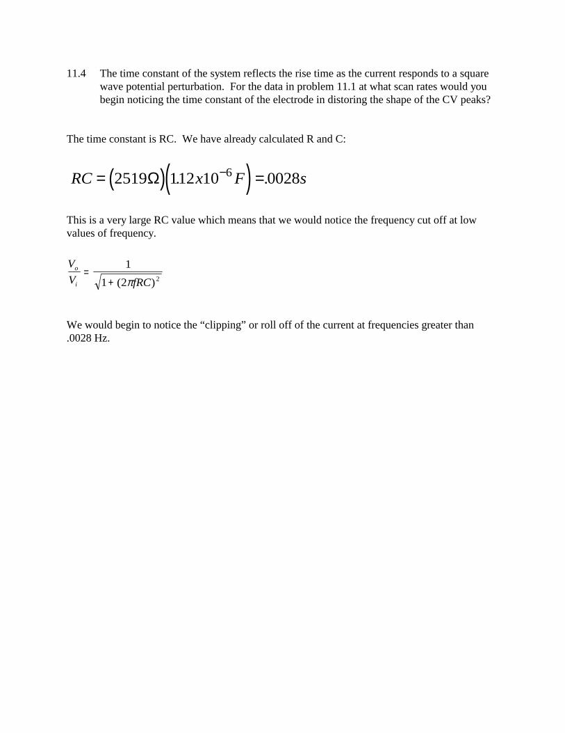
11.4 The time constant of the system reflects the rise time as the current responds to a squarewave potential perturbation. For the data in problem 11.1 at what scan rates would youbegin noticing the time constant of the electrode in distoring the shape of the CV peaks?
The time constant is RC. We have already calculated R and C:
( )( )RC x F s= =−2519 112 10 00286Ω . .
This is a very large RC value which means that we would notice the frequency cut off at lowvalues of frequency.
We would begin to notice the “clipping” or roll off of the current at frequencies greater than.0028 Hz.

11.5 What is the IR error expected at E0 in a thin layer cell of dimension 5 u width where theorifice lies 2 mm from the working electrode. A solution of 0.2 M NaCl was used as anelectrolyte and 2 mM Fe(CN)6
3- is electrolyzed.
Here we need to know the size of the orifice. We were only given one dimension so letsassume that the length of the slip is 1 cm. This orifice area is therefore 5x10-4cm by 1 cm = 5x10-
4 cm2. The length is 2 mm (0.2 cm). From Figure 11.11 we calculate the resistance to be:
( )
( )( ) ( )( )
( )
( )( )( )( )
RA
cm
x cm
concentration v v
x x Smmol
molcm
cmm
cmS
RA
cm
x cm
o solution Na Nao
Cl Clo
= =
= =+
=
+ + −
= =
= = =
−
− −
−
−
ρ ρ
ρ
ρ
ρ
ρ ρ
0 2
5 10
1 1
0 2
1
1501 10 176 3 10 0 210
100
1
2528 10 1039 56
0 2
5 10158 24
2 2
4 42
3 3
2
4
2 2
.
.
. . .
..
..
,Λ Λ Λ
Ω
The current to be expected in this system can only be calculated with some assumptions aboutthe type of experiment to be performed. Let’s assume a CV experiment at 5 mV/s.
The Faradaic current is assumed to be the largest part of the current. In this case the thin layerpeak current is calculated from equation 11.18:
( ) ( )( )( ) ( )
i n F VCRT
ix C
molVs
cm cm x cm x molcm
cmm
JKmol
K
peak thinlayerbulk
,
. .
.
=
=
− −
2 2
2 42
4 33 3
34
1 9 6484 10 0 005 1 1 5 10 2 1010
100
4 8 314 273
υ

( )( )( ) ( )
( ) ( )( )( )( )( )
i
mol emol
x Cmol e
Vs
cm cm x cm x molcm
JKmol
K
ix x x C V
Jsx C
sCVJ
A
=
= = =
− −
− −−
1 9 6484 10 0 005 1 1 5 10 2 1010
4 8 314 273
9 6484 10 0 005 5 10 2 10
4 8 314 273512 10 512
24
24 3
3 3
4 2 4 6 26
. .
.
. .
.. . µ
The IR error will be 0.8 mV.

C A Ab
C A Ab
oxox baseline
baseline
= −
= −ε
εmaxmax
CC
A Ab
A Ab
A AA A
red
ox
ox
ox baseline
ox
ox baseline=
−
−= −
−
maxmaxε
ε
11.6 Derive an expression which relates absorbance of the reduced species to E applied.
Start with the Nernst and absorbance equations:
E E RTnF
dOx
A bC
o
ox ox
= −
=
ln [Re ][ ]
ε
For the absorbance measurements we must account for any baseline absorbance that remainseven when all of our oxidized material is reduced.
Where Amax is the maximum absorbance obtained when everything in the cell is oxidized. Invoke a mass balance expression:
C C CsoC C C
C A Ab
A Ab
A Ab
total ox red
red total ox
redbaseline ox baseline ox
= +
= −
= − − − = −max maxε ε ε
So now we can get the ratio of red/ox by:

E E RTnF
A AA A
o ox
ox baseline= − −
−ln max
This last expression is substituted into the Nernst equation:

11.8 If a thin layer cell has the dimensions of 1cmx1cmx10um and a 1 mM solution ofFe(CN)6
3- how much charge will be passed when the potential is stepped to E0?
This problem does not tell us what the original potential is, however if we assume that theinitial potential is sufficiently positive of the formal potential that everything within the cell isoxidized stepping to E0 will reduce exactly ½ of the cell contents. Using equation 11.4 we cancalculate:
( )( )( )( )( )( )
Q nFN nFVC
Q mole emole
x Cmole e
cm cm x cm x molcm
Q x x x C x C
= =
=
= =
− −
− − −
1 9 6484 10 1 1 1 10 1 1010
9 6484 10 1 10 1 10 9 6484 10
4 4 33 3
4 4 6 6
.
. .
11.9 Explain the CV shape changes in Figure 11.31 obtained at a wall-jet electrode forFe(CN)6
2-.
The Cvs are all obtained at the same scan rate. What changes i the wall jet flow ratewhich increases from 1 to 10 mL/min. The diffusion layer is being pushed from a distance farfrom the electrode where diffusion is observed in the peak shaped lower CV to a diffusion layercloser and closer to the electrode. As the diffusion layer is decreased the effect is to increase theconcentration gradient and to prevent diffusional peak from developing during the time frame ofthe CV.