appendix 13.1 navigational risk...
TRANSCRIPT

Appendix 13.1
Navigational Risk Assessment

Dounreay Tri Floating Wind Demonstration
Project
Marine Safety Navigational Risk Assessment
Report to Hexicon
Issued by Aquatera Ltd
P686 – September 2016

Aquatera Ltd / Dounreay Tri Ltd / Dounreay Tri Floating Wind Demonstration Project / NRA
(This page is intentionally blank)

Aquatera Ltd / Dounreay Tri Ltd / Dounreay Tri Floating Wind Demonstration Project / NRA
This report was completed for:
Dounreay Tri Ltd
1 Exchange Crescent
Conference Square
Edinburgh
EH3 8UL
This study was completed by:
Aquatera Ltd
Old Academy
Stromness
Orkney
United Kingdom
KW16 3AW
Tel: 01856 850088
Email: [email protected]
Revision record
Revision Number Issue Date Revision Details
Rev 1.0
30/03/16 Issue first Draft
Rev 1.1
06/06/16 Approved following HIRA review

Aquatera Ltd / Dounreay Tri Ltd / Dounreay Tri Floating Wind Demonstration Project / NRA
Contents
Contents ................................................................................................................................. iv
List of Figures ......................................................................................................................... viii
List of Tables ............................................................................................................................ x
Abbreviations ......................................................................................................................... xi
1 Introduction ................................................................................................................... 1
1.1 Background ............................................................................................................................... 1
1.2 Objectives ................................................................................................................................. 1
1.3 Scope and Boundaries .............................................................................................................. 2
1.4 Guidance and Proportionate Approach Overview ................................................................... 3
1.5 Consultation .............................................................................................................................. 3
2 Risk Claim Supported by Reasoned Argument and Evidence ............................................. 4
2.1 Risk Claim .................................................................................................................................. 4
2.2 Supporting Reasoned Argument .............................................................................................. 4
2.3 Overview of Evidence ............................................................................................................... 5
2.4 Tools and Techniques Used ...................................................................................................... 6
3 Description of the Marine Environment ........................................................................... 8
3.1 Description of the Current Marine Environment ..................................................................... 8
3.1.1 Sources of information ................................................................................................ 8
3.1.2 Natural marine environmental features of the Project area ....................................... 8
3.1.3 Navigational features of the surrounding Project area ............................................. 10
3.2 Description of Future Marine Environment ........................................................................... 13
3.2.1 Marine renewables potential developments ............................................................ 13
3.2.2 Future marine traffic .................................................................................................. 13
4 Project Description ....................................................................................................... 15
4.1 Introduction ............................................................................................................................ 15
4.2 Site Selection and Consideration of Alternatives ................................................................... 16
4.3 Offshore Infrastructure ........................................................................................................... 18
5 Analysis of Marine Traffic .............................................................................................. 30
5.1 Methodology .......................................................................................................................... 30
5.1.1 Appropriate level of traffic assessment ..................................................................... 30
5.1.2 Project area ................................................................................................................ 30
5.1.3 Vessel categories considered ..................................................................................... 30
5.2 Sources of Information ........................................................................................................... 30
5.2.1 Automatic Identification System (AIS) data ............................................................... 31
5.2.2 Vessel Monitoring System (VMS)............................................................................... 31
5.2.3 Scotmap ..................................................................................................................... 32
5.2.4 Recreational vessels data........................................................................................... 32

Aquatera Ltd / Dounreay Tri Ltd / Dounreay Tri Floating Wind Demonstration Project / NRA
5.2.5 Consultation ............................................................................................................... 32
5.2.6 Data resilience and confidence limits ........................................................................ 33
5.3 Overview of Traffic Analysis ................................................................................................... 40
5.4 Cargo vessels........................................................................................................................... 42
5.4.1 Analysis ...................................................................................................................... 42
5.4.2 Data resilience and confidence .................................................................................. 44
5.5 Tanker Traffic .......................................................................................................................... 44
5.5.1 Analysis ...................................................................................................................... 44
5.6 Passenger Vessel Traffic ......................................................................................................... 46
5.6.1 Analysis ...................................................................................................................... 46
5.6.2 Data resilience and confidence .................................................................................. 48
5.7 Search and Rescue Vessels ..................................................................................................... 48
5.8 Fishing Vessel Traffic ............................................................................................................... 49
5.8.1 Analysis ...................................................................................................................... 49
5.8.2 Data resilience and confidence .................................................................................. 56
5.9 Recreational Vessels ............................................................................................................... 56
5.9.1 Analysis ...................................................................................................................... 56
5.9.2 Data resilience and confidence .................................................................................. 61
5.10 ‘Other’ AIS-Carrying Vessels ................................................................................................... 61
5.10.2 Data resilience and confidence .................................................................................. 63
5.11 Effects of Proposed Project on Vessel Traffic ......................................................................... 63
5.11.1 Vessel traffic associated with the Project .................................................................. 63
5.11.2 Presence of wind farm ............................................................................................... 65
5.12 Predicted Future Traffic Densities and Types ......................................................................... 65
5.13 Predicted Cumulative and In-Combination Effects ................................................................ 66
6 Review of Historical Maritime Incidents ........................................................................ 67
6.1 Introduction ............................................................................................................................ 67
6.2 Marine Accident Investigation Branch (MAIB) Information ................................................... 67
6.3 RNLI Information..................................................................................................................... 69
6.4 Summary of Incident Data ...................................................................................................... 70
7 Stakeholder Consultation and Hazard Review Workshop ............................................... 71
7.1 Stakeholder consultation ........................................................................................................ 71
7.2 Consultation Responses .......................................................................................................... 72
7.2.1 Maritime and Coastguard Agency (MCA) .................................................................. 72
7.2.2 Northern Lighthouse Board (NLB) ............................................................................. 72
7.2.3 UK Chamber of Shipping ............................................................................................ 72
7.2.4 Royal Yachting Association (RYA) ............................................................................... 73
7.2.5 Pentland Firth Yachting Club (PFYC). ......................................................................... 73
7.2.6 Scottish Fishermen’s Federation (SFF) ....................................................................... 73
7.2.7 UK Hydrographic Office (UKHO) ................................................................................ 73

Aquatera Ltd / Dounreay Tri Ltd / Dounreay Tri Floating Wind Demonstration Project / NRA
7.3 Hazard Identification and Risk Analysis (HIRA) Workshop ..................................................... 73
7.3.1 Introduction ............................................................................................................... 73
7.3.2 Attendees ................................................................................................................... 74
7.3.3 Hazards identified ...................................................................................................... 75
7.3.4 Risk ranking process ................................................................................................... 77
8 Status of Hazard Log and Risk Control Register .............................................................. 78
8.1 Status of Hazard log ................................................................................................................ 78
8.2 Status of Risk Control Register ............................................................................................... 79
8.4 Future Development of HIRA Process, Hazard Log and Risk Control Register ....................... 80
9 Navigational Hazards and Risk Assessment .................................................................... 81
9.1 Navigational Hazards – Cases to Consider .............................................................................. 81
9.2 Base Case Without Wind Farm ............................................................................................... 81
9.3 Base Case With Wind Farm..................................................................................................... 82
9.3.1 Installation (or decommissioning) impacts ................................................................ 83
9.3.2 Maintenance activity impacts .................................................................................... 86
9.3.3 Operations phase – vessel collisions with floating platform or infrastructure ......... 88
9.3.4 Operations phase – fishing vessel gear snags on export cable.................................. 92
9.3.5 Operations phase - floating platform breaks free from moorings ............................ 93
9.4 Future Case Without Wind Farm ............................................................................................ 94
9.5 Future Case With Wind Farm – Cumulative and In-Combination Effects .............................. 94
9.6 Other Navigation Risks and Other Risks ................................................................................. 95
9.6.1 Impact on marine systems ......................................................................................... 95
9.6.2 Noise impacts ............................................................................................................. 96
9.6.3 Coastal processes ....................................................................................................... 97
10 Search and Rescue (SAR) ............................................................................................... 98
10.1 Overview ................................................................................................................................. 98
10.2 Resources ................................................................................................................................ 98
10.2.1 SAR helicopters .......................................................................................................... 98
10.2.2 RNLI lifeboats – locations and equipment ................................................................. 99
10.2.3 Medical facilities ........................................................................................................ 99
10.2.4 Salvage – Emergency Towing Vessel availability ....................................................... 99
10.2.5 Coastguard rescue teams .......................................................................................... 99
10.3 SAR liaison for Dounreay Tri Development .......................................................................... 100
10.4 Assessment of Potential Impacts and Demands on Search and Rescue Services ................ 100
11 Emergency Response Overview and Assessment .......................................................... 101
11.1 Overview ............................................................................................................................... 101
11.2 Developer’s Own Contingency Plans for its Personnel and Assets ...................................... 101
12 Through Life Safety Management ................................................................................ 102
12.1 Developer’s Safety Management System ............................................................................. 102
12.2 Updating Risk Assessments .................................................................................................. 102

Aquatera Ltd / Dounreay Tri Ltd / Dounreay Tri Floating Wind Demonstration Project / NRA
12.3 Through Life Review ............................................................................................................. 103
12.4 Compliance and Assurance ................................................................................................... 103
12.4.1 Safety management ................................................................................................. 103
12.4.2 Emergency response management ......................................................................... 103
13 Major Hazards Summary & Conclusions ....................................................................... 104
13.1 Hazards ................................................................................................................................. 104
13.2 Risk Assessment .................................................................................................................... 104
13.3 Significant Hazards Summary ............................................................................................... 104
13.4 Mitigations ............................................................................................................................ 104
13.5 Conclusions ........................................................................................................................... 105
14 References .................................................................................................................. 107
Appendix A – Formal Safety Assessment Process .................................................................. 110
Appendix B - Hazard Log ....................................................................................................... 115
Appendix C - Risk Control Log ............................................................................................... 121
Appendix D1 Risk Matrix for Most Likely Outcomes .............................................................. 125
Appendix D2 Risk Matrix for Worst Credible Outcomes ......................................................... 126
Appendix E – Summary of Vessel Transits – AIS ..................................................................... 128

Aquatera Ltd / Dounreay Tri Ltd / Dounreay Tri Floating Wind Demonstration Project / NRA
List of Figures
Figure 1.1 Chart of Dounreay site .............................................................................................. 2
Figure 3.1 Site surrounding navigational features ................................................................... 12
Figure 3.2 Dounreay tri floating wind demonstration Project area in context of other lease areas
in the PFOW 13
Figure 4.1 Offshore site, export cable corridor and onshore study area ................................ 15
Figure 4.2 Indicative construction and operation programme ............................................... 18
Figure 4.3 Floating platform concept ...................................................................................... 20
Figure 4.4 Indicative platform parameters (assuming 6MW turbines are used) .................... 20
Figure 4.5 Mooring system plan .............................................................................................. 22
Figure 4.6 Mooring system (profile) ........................................................................................ 22
Figure 4.7 Stevpris Mk 5 Drag Embedment Anchor (Image: www.vryhof.com) ..................... 23
Figure 4.8 Plough towing arrangement ................................................................................... 25
Figure 4.9 Example of a cable plough ...................................................................................... 25
Figure 5.1 EMEC’s Black Craig AIS receiver coverage .............................................................. 34
Figure 5.2 Orkney Harbour’s Wideford Hill (Kirkwall) AIS receiver coverage.......................... 34
Figure 5.3 Black Craig reception distance for the 14 day summer period .............................. 35
Figure 5.4 Black Craig reception distance for the 14 day winter period ................................. 35
Figure 5.5 Wideford reception distance for the 14 day summer period ................................. 35
Figure 5.6 Wideford reception distance for the 14 day winter period ................................... 36
Figure 5.7 Vessel traffic densities for the Project area ............................................................ 40
Figure 5.8 Cargo vessel tracks – January 18th-31st 2016 (AIS) .................................................. 43
Figure 5.9 Cargo vessel tracks – July 18th-31st 2015 (AIS) ...................................................... 44
Figure 5.10 Tanker traffic tracks – January 18th-31st 2016 (AIS) ................................................ 45
Figure 5.11 Tanker traffic – July 18th-July 31st 2015 (AIS) ........................................................ 46
Data resilience and confidence ...................................................................................................... 46
Figure 5.12 Passenger vessel tracks – January 18th-31st 2016 (AIS) ........................................... 47
Figure 5.13 Passenger vessel tracks July 18th-31st 2015 (AIS) .................................................. 48
Figure 5.14 Search and rescue vessels – July 18th-July 31st 2015 (AIS) ...................................... 49
Figure 5.15 Fishing vessels – January 18th-31st 2016 (AIS) ......................................................... 50
Figure 5.16 Fishing vessels – July 18th-31st 2015 ..................................................................... 51
Figure 5.17 VMS data for 2011, 2012, 2013 and 2014 .............................................................. 53
Figure 5.18 Scotmap data of inshore fishing vessels by type .................................................... 55
Figure 5.19 Recreational vessels – July 18th-31st 2015 (AIS) ...................................................... 57
Figure 5.20 Dive vessel transits – January 18th-31st 2016 (AIS) ............................................... 58
Figure 5.21 RYA Coastal Atlas – routes in PFOW ....................................................................... 59
Figure 5.22 Recreational vessels AIS track density overlaid on RYA routes (Marine Scotland, 2012)
60
Figure 5.23 AIS vessel tracks classified as ‘Other’ July 18th-31st 2015 ....................................... 62

Aquatera Ltd / Dounreay Tri Ltd / Dounreay Tri Floating Wind Demonstration Project / NRA
Figure 5.24 AIS vessel tracks classified as ‘Other’ January 18th-31st 2016 ............................... 63
Figure 6.1 Locations of significant incidents reported to MAIB over the past decade ........... 69
Figure 10.1 Shetland SAR area ................................................................................................... 98

Aquatera Ltd / Dounreay Tri Ltd / Dounreay Tri Floating Wind Demonstration Project / NRA
List of Tables
A summary of the data sources used in the analysis of marine traffic is provided in Table 5.1. .. 37
Table 5.1 Summary of data sources ....................................................................................... 37
Table 5.2 Vessel type by distribution ..................................................................................... 41
Table 5.3 VMS observations 2011, 2012 and 2013 ................................................................ 52
Table 5.4 Other recreational vessel activities ........................................................................ 60
Table 5.5 Vessel requirements and durations of key installation activities ........................... 64
Table 6.1 Review of historical incident data in the vicinity of the Project area over the last 10
years 67
Table 6.2 List of Royal National Lifeboat Institution call outs 2011-2015 for the Project area +
10nm zone 69
Table 7.1 People/organisations invited to take part in HIRA event ....................................... 74
Table 10.1 RNLI distance to site ............................................................................................... 99
Table A-1 Hazard log entry content ............................................................................................. 110
Table A-2 Frequency Definitions .................................................................................................. 111
Table A-3 Consequence severity definitions ................................................................................ 111
Table A-4 Risk matrix ................................................................................................................... 112
Table A-5 Risk severity definitions ............................................................................................... 112
Table D-1 Risk Matrix for Most Likely Outcomes ......................................................................... 126
Table D-2 Risk Matrix for Worst Credible Outcomes ................................................................... 127

Aquatera Ltd / Dounreay Tri Ltd / Dounreay Tri Floating Wind Demonstration Project / NRA
Abbreviations
ADCP - Acoustic Doppler Current Profiler
AfL - Agreement for Lease
AHTS - Anchor Handling Tug Supply Vessel
AIS - Automatic Identification System
ALARP - As Low As Reasonably Practicable
AoS - Area of Search
ATBA - Area To Be Avoided
BGS - British Geological Survey
BTA - British Tug Owners Association
CA - Cruising Association
CAA - Civil Aviation Authority
CAST - Coastguard Agreement for Salvage and Towage
EIA - Environmental Impact Assessment
EMP - Environmental Management Plan
ERCoP - Emergency Response Cooperation Plan
ERP - Emergency Response Plan
ES - Environmental Statement
ETVs - Emergency Towing Vessel
FMECA - Failure Modes and Effects Criticality Matrices
GPS - Global Positioning System
GRT - Gross Registered Tonnage
HAT - Highest Astronomical Tide
HIRA - Hazard Identification and Risk Analysis
HW - High Water
IALA - International Association of Lighthouse Authorities
ICES - International Council for the Exploration of the Seas
IMO - International Maritime Organisation
LAT - Lowest Astronomical Tide
MCA - Maritime and Coastguard Agency
MGN - Marine Guidance Note
MHWN - Mean High Water Neaps
MHWS - Mean High Water Springs
MLWN - Mean Low Water Neaps
MLWS - Mean Low Water Springs
MRCC - Maritime Rescue Coordination Centre
MRCC - Maritime Response and Co-ordination centre
MSL - Mean Sea Level
MW - Megawatt
NLB - Northern Lighthouse Board
Nm - Nautical Mile
NRA - Navigation Risk Assessment
NtM - Notices to Mariners
O&M - Operation and Maintenance
OFA - Orkney Fisheries Association
OIC - Orkney Islands Council
OREI - Offshore Renewable Energy Installation
PEXA - Practice and Exercise Area
PFOW - Pentland Firth and Orkney Waters
PHA - Preliminary Hazard Analysis

Aquatera Ltd / Dounreay Tri Ltd / Dounreay Tri Floating Wind Demonstration Project / NRA
PLGR - Pre-Laying Grapnel Run
PLN - Port Letter Number
RIB - Rigid Hull Inflatable Boat
RNLI - Royal National Lifeboat Institution
RYA - Royal Yachting Association
SANAP - Strategic Area Navigational Appraisal
SAR - Search and Rescue
SCA - Scottish Canoe Association
SCADA - Supervisory Control and Data Acquisition
SFF - Scottish Fishermen’s Federation
SPV - Special Purpose Vehicle
SSEPD - Scottish and Southern Energy Power Distribution
TCE - The Crown Estate
UKC - Under Keel Clearance
UKHO - United Kingdom Hydrographic Office
VHF - Very High Frequency
VMS - Vessel Monitoring System
VTS - Vessel Traffic Service
WTG - Wind Turbine Generator

Aquatera Ltd / Dounreay Tri Ltd / Hexicon / Navigational Risk Assessment / July 2016 1
1 Introduction
1.1 Background
Aquatera Ltd (Aquatera) has been commissioned by Hexicon to carry out the Navigational Risk
Assessment (NRA) of the proposed Dounreay Tri Project (referred to as ‘the Project’ and described in
Section 4). The proposed Project will be located within an Area of Search (AoS) off the Caithness
coast, shown as ‘offshore site’ in Figure 1.1. An area comprising the ‘offshore site’ and ‘export cable
corridor’ (Figure 1.1) is referred to throughout this NRA as the ‘Project area’, while the immediate
area taken up by the floating platform and its associated moorings, which is yet to be confirmed, is
referred to as ‘the site’.
The Project consists of a semi-submersible floating platform with two wind turbine generators
(WTGs) attached. Power will be exported from the site via a static export cable to a landfall site
located immediately to the west of the Dounreay restoration site within the export cable corridor
and onwards overland to the national grid network. The floating platform covers a sea surface area
of approximately 0.17km2, while its moorings and anchors extend to an area approximately 2km2
across the seabed. The applicant has studied an area which is purposefully larger than required, i.e.
25km2, in order to maintain enough flexibility to move the platform, within this area, to avoid or
offset potential conflicts. It is intended that routine maintenance be carried out onsite during
suitable weather windows, however if significant repairs are required the floating platform will be
towed to a suitable harbour in order to facilitate repairs.
The NRA forms part of the Environmental Impact Assessment (EIA) and is available for review as part
of the Environmental Statement (ES). Guidance covering the preparation of an NRA is provided by
the Maritime and Coastguard Agency (DECC/MCA 2013) and in MCA’s Marine Guidance Note 543
(M+F) (MCA 2016).
The NRA is focused on assessing the marine navigational risk of the Project and demonstrating that
sufficient risk controls are in place for the assessed risk to be judged as ‘tolerable’. The submission
also provides information on the proposed development and its potential impacts, in the context of
the navigational activity and marine environment in the surrounding area.
1.2 Objectives
The main objective of the NRA is to demonstrate that sufficient risk controls are in place for the
assessed risk to be considered broadly acceptable or tolerable. The objective is achieved by:
• Identifying key features of the marine environment around the Project, such as bathymetry,
metocean conditions, port and harbour locations, navigational aids and restrictions;
• Describing the proposed Project and its associated vessel traffic;
• Assessing the level of vessel traffic in the vicinity of the Project using desk based data
supplemented by detailed local consultation;
• Carrying out and reporting on a structured Hazard Identification and Risk Assessment (HIRA)
process to identify and assess the safety risks associated with the Project. This process includes
stakeholder consultation;
• Assessing the level of navigational safety risk for a Base Case (i.e. current environment) with, and
without the Project. Qualitative analysis methods and expert judgement have been applied. A
Future Case assessment has also been carried out including an assessment of possible
cumulative and in-combination impacts;

Aquatera Ltd / Dounreay Tri Ltd / Hexicon / Navigational Risk Assessment / July 2016 2
• Reviewing significant hazards and proposing appropriate risk mitigation measures, and providing
a ‘risk claim supported by reasoned argument and justification’ (in Section 2) to summarise the
evidence and the claim that the Project’s impacts on navigational safety are acceptable with the
noted risk control measures; and
• Assessing Search and Rescue (SAR) provision and Emergency Response Coordination.
1.3 Scope and Boundaries
The scope of the NRA includes all phases of the Project: construction/installation, operation,
maintenance and decommissioning.
An offshore site has been identified in waters deeper than 60m (Figure 1.1). The size of the offshore
site is approximately 25km2. It is anticipated that the actual development area including anchors and
mooring lines would take up an area of the seabed approximately 2km2. The footprint of the floating
platform, including the 360° turn radius will take up an area of approximately 0.17km2. The location
of the floating platform in the offshore site is as of yet undefined. The final location of the
development area will be subject to detailed assessment of geophysical and geotechnical data in
conjunction and with agreement from stakeholders.
The boundaries of the Project area for this NRA include the offshore site together with an adjoining
export cable corridor (see Figure 1.1), collectively referred to as the Project area. Currently the
location of the operations and maintenance (O&M) base is undefined. Therefore, this NRA cannot
consider the site specific navigational risks that could occur during transit routes to the O&M base.
Figure 1.1 Chart of Dounreay site

Aquatera Ltd / Dounreay Tri Ltd / Hexicon / Navigational Risk Assessment / July 2016 3
1.4 Guidance and Proportionate Approach Overview
Guidance - the methodology used has followed the requirements and guidance noted below.
For guidance on the NRA process and reporting:
• DECC/MCA ‘Methodology for Assessing the Marine Navigational Safety & Emergency Response
Risks of Offshore Renewable Energy Installations (OREI)’ (DECC/MCA 2013).
For guidance from MCA on navigational safety issues:
• MGN 543 (M+F) “Offshore Renewable Energy Installations – Guidance on UK Navigational
Practice, Safety and Emergency Response”. (MCA 2016)
• MGN 372 (M+F) ‘Offshore Renewable Energy Installations (OREI) - Guidance to mariners
operating in the vicinity of UK OREIs’ (MVA 2008).
For guidance on formal safety assessment including the hazard identification and risk assessment
(HIRA) methodology used for the NRA:
• Health & Safety Executive Offshore Technology Report on Marine Risk Assessment (H&SE 2001).
• DNV RP-H101- Risk Management in Marine and Subsea Operations (DNV 2003).
Proportionate approach – the DECC/MCA Guidance notes the value of a proportionate approach to
NRAs for developments in areas where the potential risks are lower or a small-scale development.
Such an approach at Level 1a and 1b was provisionally agreed with MCA. Level 1 assessments are
qualitative using expert judgement. A list of key elements for such an approach is provided in Section
2.4.
1.5 Consultation
Consultation with statutory consultees, national organisations and local groups and individuals has
provided invaluable information for this NRA. This has included, for example, the Royal Yachting
Association’s (RYA) valuable position paper on wind energy developments (RYA 2015).
The consultation process is described in Section 7.

Aquatera Ltd / Dounreay Tri Ltd / Hexicon / Navigational Risk Assessment / July 2016 4
2 Risk Claim Supported by Reasoned Argument and
Evidence
2.1 Risk Claim
A navigational safety risk assessment (NRA) has been undertaken to assess the risks to navigation
arising from the Project’s development including all associated installation, operations, maintenance
and decommissioning activities. The assessment concludes that the risks are considered to be
tolerable with monitoring.
A formal safety assessment process has been used, i.e. a Hazard Identification and Risk Analysis
process (Appendix A). Risks have been systematically identified and recorded in the hazard log
(Appendix B) and control measures recorded in the Risk Control Log (Appendix C). No risks were
identified in the ‘Intolerable’ category. All risks after application of the risk mitigation measures
(noted in Appendix B) fall within the ‘As Low As Reasonably Practicable’ (ALARP) category or the low
risk ‘Broadly Acceptable’ category. All risks will continue to be monitored and additional risk
reduction measures introduced ‘So Far As Is Reasonably Practicable’.
2.2 Supporting Reasoned Argument
The navigational safety hazards associated with the proposed development have been identified and
assessed through the Hazard Identification and Risk Assessment (HIRA) process. This process is
based on guidance from DECC/MCA (DECC/MCA 2013), from MCA (MCA 2016), from HSE (HSE 2001)
and from other sources and is summarised below (see Section 2.4). The HIRA process has used
evidence from a range of data sources summarised in Section 2.3, including marine traffic analysis of
various types, local consultation and a Hazard Workshop.
All identified hazards/risk events have been identified in the hazard log (Appendix B). Significant
findings (i.e. risks assessed as greater than ‘Broadly Tolerable’) are described individually in Section 9
‘Navigational Hazards and Risk Assessment’ and summarised in Section 13 ‘Major Hazards
Summary’.
The key reasoned arguments for assessing the navigation risks as ‘Tolerable’ are based on a Level 1
approach, i.e. qualitative analysis and expert judgment of appropriate evidence together with
consultation. These are listed below.
• The traffic analysis is judged to be current, comprehensive and resilient. It shows that the area of
study carries a mix of commercial, fishing and recreational traffic which is of moderate to low
density. Very little passenger vessel traffic has been observed;
• The Project-specific traffic analysis is consistent with recent strategic area studies of PFOW;
• Consultation locally has identified the small fishing vessel operators for assessing movements of
vessels not tracked by AIS or VMS and for continuing liaison and notification;
• Consultation with recreational vessel organisations has identified typical traffic patterns,
although these may vary. Liaison and notification networks have been developed;
• A hazard assessment engaged expert and local participants and generated a preliminary hazard
listing, identification of ‘Most Likely’ and ‘Worst Case’ outcomes and discussion of mitigations.
All hazards identified during the hazard assessments, during consultation and arising from vessel
traffic analysis have been considered and assessed during the NRA;
• Mitigation measures which are either generally applicable or specifically targeted to particular
risks have been described. With the existing mitigations taken into account, all identified hazards

Aquatera Ltd / Dounreay Tri Ltd / Hexicon / Navigational Risk Assessment / July 2016 5
lie within the ‘Tolerable with ALARP’ or ‘Broadly Acceptable’ zones. These risks will continue to
be assessed for application of further mitigation measures;
• An important general mitigation which will be put in place is a comprehensive Safety
Management System (see Section 12.1);
• The contact and collision risk levels for the Project are judged to be relatively low because of its
location in an area of only moderate vessel traffic and the very small area extent of the floating
platform (approximately 0.17km2 within an offshore site of approximately 25km²). This is
surrounded by ample sea room for navigation around the floating platform both to seaward and
landward;
• Historical information on incidents shows the general area to be of relatively low risk;
• It is essential, as far as is reasonably practicable, to avoid vessels entering the site. The floating
platform is free to rotate 360° on its radius and any 3rd party vessel navigating near the site
would be at risk of collision. Mariners will be strongly advised not to enter the site. The options
for site designation, charting and lighting will continue to be discussed with MCA, NLB and
UKHO;
• The potential risk of the floating platform, or part thereof, breaking free and becoming a hazard
to other vessels is well mitigated by the position-monitoring and alarm systems to be fitted to
the platform;
• Risks related to under-keel clearance are not considered in this NRA as the depth from the base
of the floating platform to the clump weight will be approximately 80m and thus under-keel
clearance is not considered to pose a risk to vessels passing over the sub-sea infrastructure
associated with the floating platform (see Section 4.3 and Figure 4.6). Entanglement of fishing
gear on subsea infrastructure (when the floating platform is not on station) will be mitigated by
chart warning and continuing liaison with fishing operators;
• The risk assessment process has found that no risks lie within the ‘Intolerable’ zone. Those
judged to lie within the ‘Tolerable with application of mitigation measures to ALARP’ are
illustrated on risk criticality matrices for ‘Most Likely’ and ‘Worst Credible’ outcomes as
requested in scoping responses.
2.3 Overview of Evidence
Vessel traffic analysis (Section 5) has drawn on evidence contained within the following three
recently-published reports on the strategic area of PFOW:
• the ‘Shipping Study of PFOW’ (Marine Scotland 2012b) which recorded and analysed commercial
and recreational vessel traffic (but not fishing vessel movements);
• the ScotMap Report on a Fishing Pilot Study in PFOW (Kafas et al., 2014) which included an
assessment of small fishing vessels not necessarily tracked by AIS or VMS; and
• the Strategic Area Navigation Appraisal, or SANAP Report (Crown Estate 2013) which used
information from the reports above and added fresh AIS track data. In particular the SANAP
Report assessed traffic in the areas around each potential OREI development gathered in two 28
day periods in summer and winter 2012.
Further to this the following data was analysed to inform the Project:
• A Project-specific AIS track analysis was carried out for all vessels over a 28 day period and takes
account of seasonal variations in traffic patterns and fishing operations by analysing 14 days in
winter and 14 days in summer. This covered the offshore site and also the export cable corridor;

Aquatera Ltd / Dounreay Tri Ltd / Hexicon / Navigational Risk Assessment / July 2016 6
• In addition to AIS track analysis for the Project area, data supplied by Marine Scotland showing
VMS location data for three years (2011-2013) has been analysed;
• An extensive programme of local consultation was carried outwith fishing and recreational
vessel operators to identify small, non-AIS and non-VMS vessel activity;
• Taken together, the data and analysis are judged to be current, comprehensive and resilient; and
• Evidence on the history of incidents in a 10nm zone around the Project area was obtained from
MAIB and RNLI for analysis.
Other evidence used in the traffic analysis, the analysis of cumulative and in-combination effects and
risk assessment included:
• Description of Marine Environment (both current and predicted future cases);
• Project description and high-level sequence and plans for installation (moorings and the floating
platform), operation, maintenance & decommissioning; and
• Hazard assessment meetings.
2.4 Tools and Techniques Used
Guidance from DECC/MCA (DECC/MCA 2013) notes the importance of proportionality in selecting
appropriate tools and techniques for the NRA. Dounreay Tri Ltd has reviewed responses to the
Project Scoping Report and its accompanying Preliminary Hazard Analysis (PHA) and has discussed
an appropriate methodology with MCA. A methodology proportionate to a small scale development
in a relatively low risk area is proposed.
The methodology used for the NRA is described in the DECC/MCA Guidance (DECC/MCA 2013) as a
Level 1a and 1b assessment methodology. The approach is based on a hierarchy of appropriate
assessment, which defines the subsequent level of assessment. For the purposes of this NRA, the
process comprised an area traffic assessment of the strategic area (1a) and an area traffic
assessment of the area local to the Project area (1b). This approach, using qualitative analysis and
expert judgement was agreed in principle with MCA.
The key elements of the approach, covering both current and predicted future cases, are:
• Description of the marine environment (Section 3);
• Project scope and description (Section 4);
• Traffic analysis for both the area of study and the wider strategic area (Section 5);
• Review of historical incidents in the area (Section 6);
• Local consultation (Section 7);
• Formal safety assessment (Appendix A) generating a hazard log (Appendix B) using qualitative
techniques such as expert judgment and Risk Control Register (Appendix C);
• Status of hazard log and Risk Control Register (Section 8);
• A narrative analysis of navigational hazards and risk analysis (Section 9);
• Search and Rescue preliminary overview (Section 10);
• Emergency Response preliminary overview (Section 11);
• Through-life safety management (Section 12); and
• Major hazards summary and conclusions (Section 13).

Aquatera Ltd / Dounreay Tri Ltd / Hexicon / Navigational Risk Assessment / July 2016 7
Using the sources of evidence noted above, hazards have been identified through discussions with
Project personnel, professional mariners and stakeholders, including a HIRA Workshop. Each hazard
was risk-assessed through consultation with Project personnel and expert mariners taking into
consideration both mandatory/regulatory risk control measures and many committed additional
measures firmly adopted by the developer. For some hazards potential additional risk control
measures have been outlined for review and possible application in the future, but their potential
benefits have not been assessed nor were they factored into the risk assessment.
The HIRA process, based on HSE’s guidance on marine risk assessment (HSE 2001) is described in full
in Appendix A. The following additional appendices support this:
Appendix B The Hazard Log
Appendix C Risk Control Register
Appendix D1 The assessed risks presented in matrix form for ‘Most Likely’ scenarios
for each hazard.
Appendix D2 The assessed risks presented in matrix form for ‘Worst Credible’
scenarios for each hazard.

Aquatera Ltd / Dounreay Tri Ltd / Hexicon / Navigational Risk Assessment / July 2016 8
3 Description of the Marine Environment
3.1 Description of the Current Marine Environment
This includes a description of the natural features of the marine environment at and around the
Project area followed by a description of key navigational features in the area.
3.1.1 Sources of information
Sources of information for this chapter include data from Marine Scotland Interactive, British
Geological Survey (BGS), Seazone Solutions, UK Hydrographic Office and other published sources as
cited and included in Section 14.
3.1.2 Natural marine environmental features of the Project area
Introduction
A full description of the natural environmental features present in the Project area is presented in
Chapter 6 of the (ES) ‘Physical and Coastal Processes’. The information presented here provides a
summary of the key environmental aspects of the area.
Bathymetry
Water depths in the offshore Project area are in the range of 60m-110m. Water depth is greatest in
the north-west corner of the offshore site and decreases gradually towards the south-east corner.
Moving south along the export cable corridor the seabed shelves gently to the north-west at about
0.5°. Although not clear from data available for this location, submarine cliffs have been observed in
the Orkney/north-east coast area at water depths of approximately 10m and 45m related to still
stands occurring at around 7000 and 9500 years BP, respectively. The high resolution profile of the
potential cable route indicates the presence of the 45 m cliff structure although the steepness of the
slope was not able to be accurately determined.
Seabed conditions
The distribution of seabed sediments found off the north of Scotland’s coast reflects both the glacial
history of the area and the present hydrodynamic regime. The National Marine Landscape types
present within the Project area are ‘shelf sand plain’ in the northern offshore section and ‘shallow
sand plain’ in the south. The ‘shallow sand plain’ extends inshore to the coast along the potential
cable route.
Seabed video survey collected in the area (Moore, C.G. 2015) indicated the presence of a
predominantly sandy seabed with areas of slightly gravelly sand and other spots with muddier and
rock pavement zones. The predominant sediment type is muddy sand which extends all the way
inshore to the coastline.
The thickness of surface sediment deposits recorded in the Project area are variable and are
expected to range from less than 3m to 28m (BGS 1989). Sediment thickness decreases to
approximately 1m in the southernmost part of the Project area and at its shallowest reaches
approximately 0.1m. Sediment thickness decreases towards the coast. Analysis of ripple marks and
dunes indicate that considerable variation in the sediment thickness exists. Further analysis in the
Project area demonstrates clearly that the sediments below wave base are current rippled sands and
silts which have been derived from dynamic weathering of the Boulder clay and in particular the
Shelly till member.

Aquatera Ltd / Dounreay Tri Ltd / Hexicon / Navigational Risk Assessment / July 2016 9
Tidal range
The annual mean spring tidal range across the Project area is 3.5 m – 4 m, with a corresponding neap
range of 1.5 m – 2 m.
Table 3.1 lists selected tidal data for two locations located close to the development site. Tidal
surges caused by storms may cause short-term modification to predicted water levels and under an
extreme event (1 in 50-year return period) a surge in the order of 1.25 m could be encountered.
Table 3.1 Tidal ranges recorded in the vicinity of the development location (UKHO, 2011)
Tidal Parameter Height in Metres Above Chart Datum
Scrabster 58.37°N3.33°W
Mean High Water Spring (MHWS) 5.0
Mean High Water Neap (MHWN) 4.0
Mean Low Water Neap (MLWN) 2.2
Mean Low Water Spring (MLWS) 1.0
Mean Spring Tidal Range (MSTR) 4.0
Mean Neap Tidal Range (MNTR) 1.8
Tidal currents
The tidal currents in the Project area are generated by water moving between the North Atlantic and
the North Sea through the Pentland Firth and flow from west to east on the flood tide and east to
west on the ebb but may be modified to some extent by local conditions such as water depth and
topography.
Although tidal currents within the Pentland Firth itself are very strong the Project area lies to the
west and peak tidal current flow is relatively low at 0.5-0.75m/s for spring tides and 0.25-0.5m/s for
neap tides.
The velocity and direction of tidal currents found in Admiralty chart tidal diamond F located near the
Project area are provided in Table 3.2.
Table 3.2 Tidal current data (UKHO 2011) in vicinity of development area
Tidal State Hours Direction
(°)
Average Velocity (m/s)
Spring Neap
Before high water (Flood)
-6 262 0.9 0.5
-5 245 1.8 1.0
-4 223 1.8 0.8
-3 158 0.8 0.5
-2 134 0.8 0.4
-1 111 0.9 0.5
High water 0 078 1.0 0.6
After high water
(Ebb)
+1 052 1.1 0.6
+2 032 1.1 0.6
+3 030 0.8 0.4
+4 017 0.5 0.3
+5 299 0.4 0.2
+6 267 0.8 0.4

Aquatera Ltd / Dounreay Tri Ltd / Hexicon / Navigational Risk Assessment / July 2016 10
Wind
Annual mean wind speeds at both 80m and 100m elevation are greatest at distances furthest
offshore and are highest in the north-west corner of the Project area (up to 9-10m/s in the north-
west and 8-9m/s in the north-east). Lowest wind speeds are present in much of the middle and
south of the Project area at 80m elevation (7-8m/s). Similar wind speeds are present in the south-
east section at 100m, but are greater in the south-west (8-9m/s) (ABPmer, 2008). Wind speed and
direction has a major influence on wave and water current formation. The strength of wind and the
frequency of wind directions vary considerably over time, but, in general, winds in the north of
Scotland are predominantly from the south and west. The highest mean wind speeds and gusts are
typically recorded during the winter months (December to February), with gusts of over 100mph not
uncommon during winter storms.
Waves
Annual mean significant wave height (average height of the largest third of waves) across the
majority of the Project area is 1.75-2.0m. To the south of the Project area annual mean significant
wave height values are in the range 1.5-1.75m, decreasing closer to shore (ABPmer, 2008). Wave
heights in the region are some of the highest in the UK, with waves of up to 17m recorded at EMECs
grid connected wave test site approximately 50km north-east of the Project area.
Visibility
At Cape Wrath (approximately 19nm west of the Project area) fog (defined as visibility of less than
1km) is recorded on an average of 40 days per annum, predominantly during the summer months.
Periods of restricted visibility due to precipitation will also occur. In the winter months, daylight can
be restricted to a period of around 6-7 hours.
3.1.3 Navigational features of the surrounding Project area
Navigation
The Project area lies within the Pentland Firth and Orkney Waters (PFOW) strategic area but is
outside the actual Pentland Firth lying approximately 14nm to the western boundary at Dunnet
Head.
The Pentland Firth itself is subject to a voluntary ship reporting system whereby vessels are advised
to contact the Aberdeen Coastguard one hour before entering the Firth and again on leaving. There
are Admiralty Chart warnings about the very strong tidal streams within Pentland Firth. These
warnings also specify an Area to be Avoided (ATBA), advising laden tankers not entering Scapa Flow
to avoid the Pentland Firth in adverse weather or restricted visibility.
No navigational channels are marked on Admiralty Charts for the area surrounding this proposed
development. However, the regional shipping appraisal, SANAP, (Crown Estate, 2014) records a
higher density of shipping to the north of the Project area, most of which would be on a course from
Cape Wrath to the middle of the Pentland Firth between Stroma and Swona (Crown Estate, 2014).
The results of the vessel traffic analysis are presented in Section 5.
Orkney Vessel Traffic Service
The nearest vessel traffic service is operated by Orkney Harbour Authority, who operate a 24 hour
service (Orkney VTS) for vessels navigating into Scapa Flow and Kirkwall Bay. The radar-based vessel
traffic management system combines radar coverage with active interrogation by VHF of vessels
entering the harbour area. Vessels under 12 m overall length do not need to report to the VTS. The
service provides information on all aspects of port operations including pilotage, traffic movements,
navigation warnings, weather forecasts and berth availability (OIC, 2015).

Aquatera Ltd / Dounreay Tri Ltd / Hexicon / Navigational Risk Assessment / July 2016 11
Navigational aids
Seven lighthouses are present along the north coast of the Scottish mainland and PFOW, namely
Cape Wrath, Loch Eriboll, Strathy Point, Holburn Head, Dunnet Head, Stroma and Duncansby Head.
Aquaculture
There are no aquaculture sites in the immediate vicinity of the Project area. There are two salmon
farms and one mussel farm in Loch Eriboll approximately 50km to the west of the Project area,
which is also a classified shellfish harvesting area. The Kyle of Tongue approximately 36km west has
two mussel farms and is also a classified shellfish harvesting area. The east coast of Hoy to the north-
east has six active fish farms, the nearest of which is approximately 45km from the Project area.
Infrastructure
There are no subsea cables or pipelines that intersect with the offshore site or export cable corridor.
There are two active telecommunication cables located east of the Project area; one from Dunnet
Bay to Bay of Skaill on Orkney and another connecting Dunnet Bay to the Faroe Islands. Two active
unburied power cables (a 33kV line and 33kV cable) also run north to Orkney, from Murkle Bay near
Thurso to Rackwick Bay, Hoy, Orkney. All existing cables are at least 6nm (11km) east of the Project
area.
New transmission infrastructure is required between Orkney and Caithness to enable the export of
electricity from renewable energy generation in Orkney into the national grid. Scottish Hydro
Electric-Transmission (SHE-T) is planning to develop a 70km 220kV sub-sea electricity transmission
connection from the existing connection site at Dounreay to the Bay of Skaill on the west coast of
Orkney (SHE-T, 2013). Construction of this new network is expected in 2018/19, however this is
subject to the progress of current wave and tidal energy generation sites in Orkney and dependent
on the submission of a needs case and approval by OFGEM. (See Chapter 17: Other Users of the
Marine Environment).
Ports and harbours
The nearest industrial/fishing ports are Scrabster, Stromness and Lyness to the east and
Kinlochbervie to the west. There a r e also small slipways along the north coast including (see
Figure 3.1):
• Durness and Cape Wrath area: Keoldale West, Keoldale East, Rispond, Port Chamuill, Ard Neakie
and Portnancon;
• Tongue and Bettyhill: Talmine, Skerray, Bettyhill and Kirtomy; and
• Strath Point to Thurso: Port Grant, Portskerra, Sandside, Scrabster and Thurso.
With the exception of the large port development at Scrabster, most of the harbour facilities across
the north coast comprise small jetties, semi natural harbours, harbour walls and slipways. Use of
these facilities includes dedicated passenger ferries (Keodale West and East), small scale fishing
activities (Ard Neakie, Talmine, Port Grant, Portskerra), and small scale tourism (Skerray). Some
jetties are no longer used commercially but may be used for ad hoc leisure or small scale fishing
activities (Bettyhill, Kirtomy and Sandside). Several facilities are privately owned (Rispond and
Portnancon). There are limited opportunities west of Scrabster for berthing medium sized vessels or
marina facilities available until Kinlochbervie, south of Cape Wrath.

Aquatera Ltd / Dounreay Tri Ltd / Hexicon / Navigational Risk Assessment / July 2016 12
Figure 3.1 Site surrounding navigational features
Anchorages
There are no noted commercial or recreational vessel anchorages in the Project area.
Military practice areas
The Project area is located approximately 70km east of a military exercise area and Firing Danger
Area at Cape Wrath. There is also a practice and exercise area (PEXA) within Loch Eriboll, Sutherland
(within the Cape Wrath Firing Range area). Twice a year, Europe’s largest military exercise, Joint
Warrior is undertaken off the north, north-east and north-west coasts of Scotland. Joint Warrior
involves the three Armed Forces and aircraft, navy vessels, submarines and army personnel and
occurs in March/April and October each year over a period of 10 - 15 days.
Wrecks
There are no known surface piercing or partially submerged wrecks within the shipping lane or
Project area that would present a navigational hazard.
Disposal sites
None are recorded in the area.

Aquatera Ltd / Dounreay Tri Ltd / Hexicon / Navigational Risk Assessment / July 2016 13
3.2 Description of Future Marine Environment
3.2.1 Marine renewables potential developments
Dounreay Tri floating wind demonstration Project
The current planned development is to complete installation of the moorings, anchors and export
cable (anticipated to take 2-3 months, subject to weather), shortly before the platform tow and
installation. This is to limit the amount of time the moorings are in place without the floating
platform being installed, thus minimising the risk of e.g. fishing gear entanglement with the
moorings etc. The floating platform will be towed to site from an as yet undefined port with two
WTGs (max 6 MW capacity each) pre-installed, allowing swift connection of the floating platform to
the moorings and export cable which is anticipated to take around five days.
Other marine renewables developments in PFOW
The Strategic Area Navigation Appraisal (SANAP) (Crown Estate 2014) charts the Areas for Lease
granted by The Crown Estate for wave and tidal developments in PFOW (see Figure 3.2).
Figure 3.2 Dounreay tri floating wind demonstration Project area in context of other lease areas
in the PFOW
3.2.2 Future marine traffic
One future change which is likely to increase vessel traffic slightly is marine renewable energy
developments as reviewed in the SANAP (The Crown Estate 2014) strategic area study. Each will
require several specialist survey and construction vessels during construction and a smaller number
of support vessels in operation. The Project site is regarded as being well away from potential wave
and tidal energy sites around Orkney and Stroma; however the proposed Dounreay Floating Wind

Aquatera Ltd / Dounreay Tri Ltd / Hexicon / Navigational Risk Assessment / July 2016 14
Demonstration Centre (DFWDC) will be in the vicinity of the Project and will result in an increase of
vessel traffic if it is to go ahead.
It is possible that the presence of novel floating wind devices may attract visitors including media,
industry or government representatives, as well as recreational vessels as observed in Strangford
Loch in relation to tidal devices. Again, the remoteness of the Dounreay site and notification
warnings of the hazards should minimise casual visits.
An activity which has grown in recent years is passenger cruise ship visits, particularly to Orkney. For
2016 approximately 110 cruise ship visits to Orkney are forecast but only a small proportion are
likely to transit the Project area.
From stakeholder consultation, including Harbour Masters, no significant future growth in
commercial or fishing traffic was noted. The port development in Scrabster and the development of
hydrocarbon resources West of Shetland might lead to a small increase in traffic.

Aquatera Ltd / Dounreay Tri Ltd / Hexicon / Navigational Risk Assessment / July 2016 15
4 Project Description
4.1 Introduction
Hexicon is a Swedish design and engineering company that has developed a semi-submersible
foundation for offshore wind power that hosts two Wind Turbine Generators (WTGs). Hexicon
wishes to demonstrate this technology in Scottish waters.
In order to be eligible for 3.5 Renewable Obligation Certificates (ROCs) the Project must be
commissioned and connected to the grid before the 1st October 2018. Accordingly, Hexicon has
created a Special Purpose Vehicle (SPV) called ‘Dounreay Trì Limited’ for the sole purpose of
developing, financing, constructing and demonstrating this technology within a site approximately 6
km off Dounreay, Caithness (‘the site’) (Figure 4.1).
Dounreay Trì Limited (‘the Applicant’) is proposing to demonstrate a floating offshore wind farm
called Dounreay Trì (‘the Project’) which shall consist of:
• A two turbine offshore wind farm with an installed capacity of between 8 to 12 megawatts
(MW), subject to final approval of The Crown Estate, approximately 6km off Dounreay,
Caithness;
• A single export cable to bring the power to shore immediately to the west of the Dounreay
Restoration site fence line; and
• Subject to a Connection Offer from Scottish and Southern Energy Power Distribution (SSEPD),
the associated onshore electrical infrastructure to connect the Project at, or near, the existing
Dounreay 132/33/11kV substation.
Figure 4.1 Offshore site, export cable corridor and onshore study area

Aquatera Ltd / Dounreay Tri Ltd / Hexicon / Navigational Risk Assessment / July 2016 16
Figure 4.1 depicts the offshore site, the export cable corridor and the onshore study area.
Coordinates for the four corners of the offshore site are provided in Table 4.1.
Table 4.1 Offshore site coordinates
Corner Northing Westing
NW 58040’25.6” 3053’36.0”
NE 58040’27.7” 3048’25.7”
SE 58037’46.0” 3048’22.0”
SW 58037’44.0” 3053’31.9”
4.2 Site Selection and Consideration of Alternatives
Site selection – consideration of alternatives
In August 2014, Hexicon sought to locate a site in Scottish waters to demonstrate their multi-turbine
platform. Marine Scotland (2014) had published the Potential Scottish Test Sites for Deep Water
Floating Wind Technologies - Regional Locational Guidance (RLG). The Regional Locational Guidance
identified eleven sites which were considered suitable for floating wind. Accordingly, each site was
reviewed according to Hexicon’s criteria. Only three sites identified in the RLG met Hexicon’s criteria:
• North-east Aberdeen;
• North Coast (Dounreay); and
• Southern Moray Firth.
These three sites were examined in greater detail using publically available information and the
results presented at a Site Selection Workshop, hosted by Marine Scotland and attended by Scottish
marine stakeholders, in Edinburgh on the 10th October 2014.
On the basis of the information available and feedback from the workshop, the Southern Moray
Firth site appeared to be unsuitable for development. A deep trench lay landward of this site so it
would be difficult to install the marine cable successfully. The Southern Moray Firth site is also
intensively fished and is within an area which is designated for the protection of marine mammals.
The north-east Aberdeen site lay approximately 23km from shore, significantly increasing the length
and cost of the export cable. Furthermore, the site and export cable corridor lay within ground that
is fished by a range of gear types, including scallop dredgers. Scallop dredging could damage subsea
cables, so presented a significant risk for a Project which is reliant on only one export cable.
Hexicon chose the Dounreay site which lies south of the shipping traffic. The Dounreay site was
selected for the following reasons:
• The site has suitable water depths, close to shore thus reducing the export cable length and
costs compared with other sites;
• The substrate is gravelly sand;
• The average wind speed is good and has been calibrated with data from the Forss Wind Farm;
• On the basis of discussions with Scottish Fishermen’s Federation (2014), the site lies outwith
intensively fished areas; and
• Marine Scotland completed a detailed geophysical survey during the summer of 2014, including
sub-bottom profile of the site. This information is publically available.

Aquatera Ltd / Dounreay Tri Ltd / Hexicon / Navigational Risk Assessment / July 2016 17
Project objectives
The Project has two key objectives:
• Technical: To test the performance of a multi-turbine floating wind platform in a real offshore
environment; e.g. fatigue loading, power output, controls etc. and use these results to refine the
platform for larger scale Projects overseas; and
• Economic: Verification of the economic return through this demonstration Project shall provide
a base for more reliable estimations for utility scale Projects overseas. This full scale
demonstration Project is an important step towards developing a commercially competitive
product.
Design envelope
As set out further in Chapter 5: Environmental Impact Assessment Methodology, the ES will include
a clearly defined ‘Design Envelope’. The Design Envelope is also known in UK legal nomenclature as
the Rochdale Envelope1.
Key components of the Project are outlined below. At this early stage, the Design Envelope remains
indicative and will be refined following environmental surveys, technical and engineering studies and
in consultation with The Highland Council and other stakeholders.
Construction and operation programme
Figure 4.2 provides the indicative timeframe over which the Project will be constructed and
operated.
2017 2018 2018-2042 2043
Q2 Q3 Q4 Q1 Q2 Q3
Platform fabricated off- site in a
dry dock
Onshore substation construction
Onshore cable installation
Install mooring system
Install export cable
Hook up platform with WTG pre-
installed
Install scour and cable protection,
if necessary
Final commissioning
1 Case law (for example Rochdale MBC Ex. Parte C Tew 1999) has affirmed the legal principle that the content of any
consent for development requiring EIA cannot exceed the scope of EIA. However, an enduring difficulty for the
promoters of complex infrastructure Projects such as offshore wind farms is that it is not possible to be precise about
each element of a development at the time of the submission of a consent application. A valid approach to this issue is to
define a design envelope (known as a Rochdale envelope) comprising a series of realistic worst case scenarios for
individual environmental or technical disciplines, which will define the scope of the EIA and in turn the scope of any
consent or licence.

Aquatera Ltd / Dounreay Tri Ltd / Hexicon / Navigational Risk Assessment / July 2016 18
Operation
Decommissioning
Figure 4.2 Indicative construction and operation programme
4.3 Offshore Infrastructure
The main offshore components will include:
• Two offshore wind turbines;
• A semi-submersible foundation;
• Mooring clump weight;
• Mooring chain and/or steel lines;
• Drag embedment anchors;
• One cable to bring the renewable electricity ashore; and
• Scour protection for the anchors and the export cable, where necessary.
Turbine envelope
The turbine envelope sets maximum and minimum turbine dimensions against which the
environmental impacts of this Project have been assessed. These minimum and maximum
dimensions used to define the turbine envelope are based on current offshore wind turbine
technology.
Table 4.2 Turbine envelope
Nominal
Rating
Maximum
Rotor Tip
Height
(m MHWS)
Maximum
Number of
Turbines
Maximum
Rotor
Diameter (m)
Maximum Hub
Height (above
MHWS)
Minimum Air
Draft
(above MHWS)
4MW 185 2 130 120 22
5MW 186 2 132 120 22
6MW 201 2 154 124 22
Each wind turbine operates automatically. Each turbine can yaw – the nacelle rotates to face the
rotor blades into the wind. The rotor blades can also pitch – the blades can rotate into or out of the
wind depending on the wind speed. Each turbine is self-starting when the wind speed reaches an
average of about 3 to 5m/s (about 10 mph). The output increases with the wind speed until the wind
speed reaches typically 10 to 13m/s (about 25mph). At this point, the power is regulated at rated
(maximum) power. When the maximum operational wind speed is reached, typically 25 to 30m/s
(about 60mph), the wind turbine will cut-out, either fully or gradually, in order to limit loading. If the
high wind speed cut-out is gradual, the wind turbine will continue to generate some power through
to higher wind speeds, the maximum being dependent on the wind turbine design. A SCADA
(Supervisory Control and Data Acquisition) computer system monitors and controls the output from
each wind turbine. An integrated alarm system will be triggered automatically in the event of a
turbine fault.

Aquatera Ltd / Dounreay Tri Ltd / Hexicon / Navigational Risk Assessment / July 2016 19
Turbine installation
The wind turbines will be installed and commissioned at the fabrication port, prior to transit to the
Dounreay site.
Safety requirements
The Project will be designed and constructed to satisfy the safety requirements of the Maritime and
Coastguard Agency (MCA) as well as the marking, lighting and fog-horn specifications of the Civil
Aviation Authority (CAA) and the Northern Lighthouse Board (NLB). At present, requirements specify
that the turbines must be marked with lights that are visible from 2nm. The Project shall be marked
on navigational charts.
When in operation, the platform shall be marked with clearly visible unique identification characters,
which will be visible from all sides and comply with applicable requirements in Maritime and
Coastguard Agency Marine Guidance Notice MGN 543. Currently these recommend that they should
be visible from at least 150m from the structure and permanently lit by down lights to minimise light
pollution. The colour scheme of the turbine tower, nacelle and blades is likely to be light grey RAL
7035, white RAL 9010 or equivalent.
The platform
The platform is a large, floating, semi-submersible platform supporting two WTGs. The exact size of
the platform shall be determined by the rotor diameter of the turbines used. Table 4.3 sets out the
indicative platform length and other dimensions in relation to the turbine envelope.
Table 4.3 Indicative platform dimensions
Turbine Options
Aspect 4MW 5MW 6MW
Length 195m 200m 230m
Width 105m 110m 135m
Height above water surface 15m 15m 15m
Draft (transit) 8.5m 8.5m 8.5m
Draft (operational) 15m 15m 15m
Total displacement 14100 Te 15200 Te 23000 Te
The topside of the platform would be painted yellow to improve visibility and provide corrosion
protection. Figure 4.4 provides further illustration. Figure 4.3 provides indicative details of the
platform dimensions and parameters when utilizing 6MW turbines with a rotor diameter of 154m.
The platform including the 360o turn radius and allowing for some lateral movement, would occupy
a sea surface area of approximately 0.17km2.

Aquatera Ltd / Dounreay Tri Ltd / Hexicon / Navigational Risk Assessment / July 2016 20
Figure 4.3 Floating platform concept
Figure 4.4 Indicative platform parameters (assuming 6MW turbines are used)
The process for the platform construction and installation shall be as follows:
• The steel is rolled at a steel yard;
• The buoyancy columns are fabricated at a steel or construction yard;
• The steel components are shipped by barge to a dry dock facility for fabrication;

Aquatera Ltd / Dounreay Tri Ltd / Hexicon / Navigational Risk Assessment / July 2016 21
• The turbines are shipped to the dry dock, hoisted onto the platform and are commissioned
whilst in the dock;
• The platform, with turbines installed, is floated out of the dry dock and towed by up to 4 tugs to
the offshore site;
• The platform is connected to the mooring system and export cable; and
• The Project undergoes final checks before exporting power.
The tow shall be completed by up to four anchor handling tugs with support and guard vessels
(Table 4.4). The installation of the platform may require four anchor handling tugs to hold the
platform in position with a dive support vessel onsite to connect the platform to the mooring lines
and export cable. A Notice to Mariners would be promulgated to local ports and marine users prior
to transit and installation works. Local vessels may be employed as guard vessels.
Table 4.4 Platform tow out and installation vessels
Installation
Details Requirement Value
Tow out and
positioning Description
Up to 4 Anchor Handling Tug Supply
(AHTS) vessels.
Connection of
mooring
system and
export cable
Description
Up to 5 support vessels.
This will include up to 4 crew transfer
boats, 1 dive support vessel and up to 2
guard vessels
Safety zone
A declaration shall be sought from Scottish Ministers for a 500m safety zone around construction
works within the offshore site.
Mooring system
The platform must rotate 360o in order to reduce wake effects (i.e. turbulence) between the
turbines. Wake effects can occur when one turbine is downwind of the other. The platform shall use
a passive mooring system which aligns with the prevailing tidal, wind and wave conditions similar to
the way a boat swings at anchor.
The mooring system shall consist of up to 8 mooring lines which are anchored to the seabed. The
mooring lines shall pass through a 600 tonne clump weight (50m by 50m) which shall be suspended
in the water beneath the platform. This clump shall hold the anchor lines taut in the water column
beneath the platform. The clump weight shall act like a pendulum which dampens lateral
movement.
The mooring system is shown in plan view in Figure 4.5 and in profile in Figure 4.6. There are up to 8
mooring lines for holding the platform in position.
The anchors would have a maximum radius of 800m from the platform centre and occupy an area of
approximately 2km2 on the seabed.

Aquatera Ltd / Dounreay Tri Ltd / Hexicon / Navigational Risk Assessment / July 2016 22
Figure 4.5 Mooring system plan
Figure 4.6 Mooring system (profile)
The clump weight shall be brought to site ahead of the platform. The clump weight shall be lowered
on the seafloor, temporarily. Once the platform is in place then the clump weight shall be hoisted
from the seafloor and remain suspended beneath the platform during operation.
The plinth for the clump weight may require dredging to level the seabed. Dounreay Trì Limited are
currently (September 2016) conducting a geophysical survey within the site to determine the
sediment depth and firmness within the Site. The plinth would measure approximately 70m by 70m
and may need to be dredged to a maximum depth of 5m. The approximate volume of dredge
material would be 24,500m3. The dredged material would be replaced by clean, crushed stone. The
dredged material has not yet been characterised so a proper assessment cannot be made of its
potential impacts on human health and the environment, consequently it shall not be disposed of at
sea. The dredged material shall be disposed of at a licenced site onshore.
Dounreay Trì Limited shall require a separate Marine Licence to dredge an area beneath the
platform, in order to level it. The need for dredging shall not be confirmed until the detailed design

Aquatera Ltd / Dounreay Tri Ltd / Hexicon / Navigational Risk Assessment / July 2016 23
of the platform is complete. If dredging is required then Dounreay Trì Limited understands that
sediment samples must be collected, analysed and provided to MS-LOT prior to support another
Marine Licence application for dredging. Any dredging licence application would be made separately
to this application and subject to additional consultation. Dounreay Trì Limited has considered the
environmental effects associated with dredging in this Environmental Statement to the extent that is
possible but Dounreay Trì Limited accepts that further environmental assessment would be
necessary to support any additional Marine Licence for dredging.
Mooring lines
The mooring lines are most likely to be chain, steel wire or a combination thereof. Offshore grade
mooring chains of 100mm to 160mm diameter may be used.
The 8 mooring lines are each approximately 800m long and may be slack. For the purposes of the
assessment it is assumed that up to 75% of each mooring line could come into contact with the
seabed.
Anchors
Drag embedment anchors shall be used. The holding capacity of a drag embedment anchor is
generated by the resistance of the soil between the anchor and the platform. It is possible to add
more than one anchor to each mooring line in order to increase the holding capacity. The platform
may require up to two anchors on each mooring line so up to 16 drag embedment anchors in total.
Each anchor shall be up to 9m long and 9m wide, assuming 30 ton Stevpris Mk 5 anchors are used
(Figure 4.7). These drag embedment anchors are design to penetrate 10-15m into the seabed,
subject to seabed conditions. The anchors would be installed by an Anchor Handling Tug Supply
vessel.
Figure 4.7 Stevpris Mk 5 Drag Embedment Anchor (Image: www.vryhof.com)
Scour protection
Scour protection is designed to prevent structures being undermined by sediment processes and
seabed erosion. The impacts of scour can be managed by protecting the seabed around the base of
the anchors and the export cable. Several types of scour protection exist, including mattress
protection, sand bags, grout-filled bags, stone bags and artificial seaweeds. However, the placement
of large quantities of crushed rock around the base of the foundation structure is the most
frequently used solution. The base case is that no scour protection is required; however if scour
protection were to be used, then the foot print would extend no more than 20m out from the centre
of the anchor and to a height of 2m above the seabed (Table 4.5).

Aquatera Ltd / Dounreay Tri Ltd / Hexicon / Navigational Risk Assessment / July 2016 24
Table 4.5 Scour protection details
Scour Protection Unit Measurement
Type of scour protection - Rock
Diameter of rocks used m 0.06-0.65
Height of scour protection above original seabed m 2
Extent of scour protection (from centre of
anchor) m 20
Seabed area take (per anchor) m2 1,260
Anticipated number of vessels required including
support vessels - 2
Vessel type -
Dynamically positioned fall-pipe
vessel
Crew transfer vessel
Intra-array cables
Intra-array cables shall connect the two wind turbines. These cables shall be integrated into the top-
side of the platform.
Export cable
The export cable shall be buried in the seabed between the site and the landfall. The export cable
will make landfall in an area immediately to the west of the Dounreay restoration site (Figure 4.1).
The export cable would be between 6 and 13.8km in length, depending on the final position of the
platform within the site.
The marine cable shall include conductor cores and a fibre optic cable encased in one cable which is
armoured. The copper or aluminium conductors are covered by an insulation of polyethylene (cross
linked XLPE) or EPR (Ethylene Propylene Rubber). The insulation is contained within an insulation
screen, a lead alloy sheath (to ensure no ingress of water into the insulation). The diameter of the
cable would be a maximum of 0.5m.
The portion of the cable closest to the platform shall be dynamic so the platform can rise and fall
without stretching or snapping the cable. A dynamic cable would typically be suspended in a “lazy-
wave” (s-shape) acting like a flexible riser would on an oil and gas platform. Buoyancy elements lift
the cable from the seabed and suspend it in the water column, well below the sea surface. The cable
shall touchdown on the seabed approximately 250m beyond the platform. Approximately 20% (50m)
of the dynamic cable may come into contact with the seabed as the platform moves. A small drag
embedment anchor or clump weight shall stabilise the export cable touchdown. Thereafter the
export cable will be buried under the seabed with a target burial depth of 1-2m.
Ploughing is the preferred cable installation method (see Figure 4.8 and Figure 4.9). Although jetting
or vertical injection may be used where local sediments require. The export cable will be buried
within a trench up to maximum 8m wide and up to 2m deep. Depending on seabed conditions along
the export cable corridor it may not be possible to bury the full length of cable to the desired depth.
Where it is not possible to bury the cable, rock may be required to protect the cable. As a worst case
it is assumed that a maximum of (20%) 2.8km of cable may require protection.
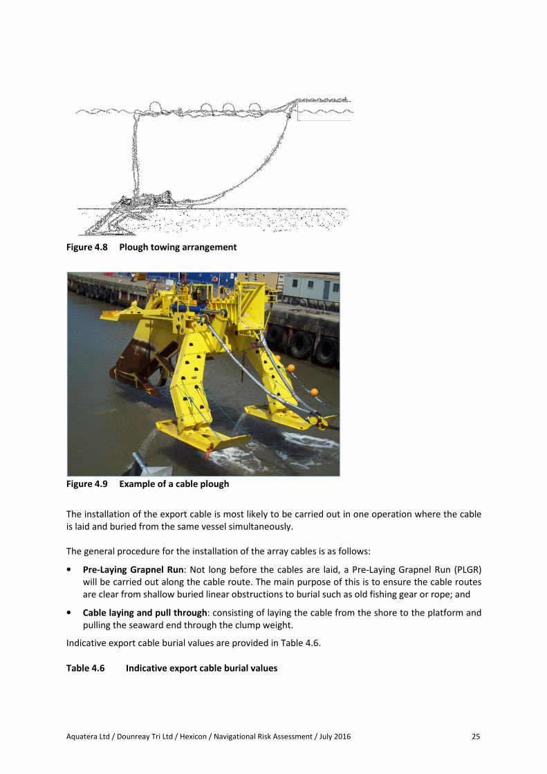
Aquatera Ltd / Dounreay Tri Ltd / Hexicon / Navigational Risk Assessment / July 2016 25
Figure 4.8 Plough towing arrangement
Figure 4.9 Example of a cable plough
The installation of the export cable is most likely to be carried out in one operation where the cable
is laid and buried from the same vessel simultaneously.
The general procedure for the installation of the array cables is as follows:
• Pre-Laying Grapnel Run: Not long before the cables are laid, a Pre-Laying Grapnel Run (PLGR)
will be carried out along the cable route. The main purpose of this is to ensure the cable routes
are clear from shallow buried linear obstructions to burial such as old fishing gear or rope; and
• Cable laying and pull through: consisting of laying the cable from the shore to the platform and
pulling the seaward end through the clump weight.
Indicative export cable burial values are provided in Table 4.6.
Table 4.6 Indicative export cable burial values

Aquatera Ltd / Dounreay Tri Ltd / Hexicon / Navigational Risk Assessment / July 2016 26
Cable Parameter Requirement Value
Specification Range AC Cable
Diameter (including armour and insulation) – up to 0.5m
Length Range 6 – 13.8km
Burial depth Range
Generally the cable will be buried at 1 – 2m. In extreme
cases this can be as high as 3m. Sections of the cables will
be surface laid if soil conditions are hard and/or the risk of
cable damage is very low.
Width of seabed
affected per cable
during burial
Max 1-8m depending on soil conditions and burial method
Burial spoil
Jetting
Jetting may cause sediment suspension. This volume of
sediment suspension depends on the soil conditions. For
the calculation of the maximum volume of the sediment
suspension, it can be assumed that there is 100% sediment
suspension along 95% of the total cable length from a
trench up to 3m deep and 0.6m wide. It should be noted
that this is based on burial with a jet and does not
represent the actual shape of the trench which in reality
could be wider and v-shaped.
For the remaining 5%, it can be assumed that there is 100%
sediment suspension from a trench up to 10m deep and
1m wide with straight sides. It should be noted that this is
based on burial with a vertical injector and does not
represent the actual shape of the trench which in reality
could be wider and v-shaped.
Ploughing
Ploughing will not result in substantive sediment
suspension.
Spoil will be pushed up out of the trench to lay in a berm
on either side. A multi-pass plough will dig a v-shaped
trench up to 2m deep and 3m wide. Spoil can be backfilled
if required.
Type of cable
protection - Rock
Diameter of rocks
used m 0.06-0.65
Height of cable
protection above
original seabed
m 2
Width of cable
protection m 8
Length of cable
protection m 2,800
Seabed area take m2 22,400
Anticipated
number of vessels
required including
support vessels
- 2
Vessel Type - Dynamically Positioned Fall-pipe Vessel
Crew transfer vessel

Aquatera Ltd / Dounreay Tri Ltd / Hexicon / Navigational Risk Assessment / July 2016 27
Cable crossings
There are no known active or inactive cables within either the offshore site or export cable corridor.
Offshore substation
This Project shall not require an offshore substation.
Offshore anemometer mast
This Project shall not require an offshore anemometer mast.
Fabrication and installation activities
The platform is a steel truss structure with welded steel joints. The basic premise of the fabrication
and installation methodology is as follows:
• Rolling of steel and fabrication of sections of the platform, Scottish fabrication options are being
explored;
• Joining of the sections of the platform in a dry dock;
• Turbine installation and commissioning in the dry dock;
• While the fabrication is taking place, the subsea cable, anchors, mooring lines and clump weight
will be installed at the Dounreay site. The lines will be buoyed and marked as required, ready for
installation of the platform. Anchor handling and installation can be carried out from a local port
using local support vessels, where possible. Cable laying and particularly anchor installation will
be done as late as possible prior to platform installation to minimise risks to the components
and shipping. Scour protection for the anchors and cable may be required depending on the
seabed conditions and the metocean conditions experienced at the site;
• Tow the platform to site and then hook up to the export cable and the anchor lines; and
• Final testing and export power.
The environmental management of construction activities will be carried out under the provisions of
an Environmental Management Plan (EMP), which will be agreed with key stakeholders prior to
construction. The provisions of an EMP typically include issues such as fuel and chemical handling,
pollution prevention and control and storage of waste and effluent.
Programme of works (offshore)
Approximate durations for typical construction activities associated with individual components are
provided below:
• Fabrication and turbine installation may take approximately 12 - 18 months. The platform shall
be fabricated in a dry dock, off site; and
• Subsea cable, anchors and mooring lines would be installed at the Dounreay site, as will the
anchors and mooring lines. This would take 2 - 3 months, subject to weather.
The overall programme of works would likely remain 12 - 18 months as the fabrication of the
platform and installation of the cable, anchors and moorings would occur in parallel.
Operations and maintenance
Once operational, the Project will require regular inspections, servicing and maintenance throughout
its lifetime. This will require technicians and support staff. Given the distance of the Project from

Aquatera Ltd / Dounreay Tri Ltd / Hexicon / Navigational Risk Assessment / July 2016 28
shore and the Project size, it is assumed that an Operations and Maintenance (O&M) hub at an
existing port may be required. The O&M hub would be shortlisted and selected during the consent
determination period. O&M vessels would steam between the port and the Project. Operations and
maintenance activities will be defined within the Design Envelope and addressed in the relevant
technical chapters of the ES.
Turbine maintenance falls into two categories: Preventative maintenance and corrective
maintenance. Preventive maintenance will be mostly undertaken using crew vessels (although
helicopters could be used in certain circumstances) to access the turbine and includes tasks such as
the replacement of consumables (filters and oil) as well as a general inspection of the turbine. Crew
transfers from vessels are expected to be via boat landing whereas helicopter access will be via heli-
hoist. Corrective maintenance includes minor repairs/restarts and major component replacements
(such as generator, blades, etc.). This is required if the results of condition monitoring or preventive
maintenance suggest it is necessary, or if monitoring alarms are triggered (some of which may result
in the wind turbines being remotely shutdown). It is expected that on average up to eight visits per
turbine, per year will be required for fault rectification and up to three per turbine, per year for
major component replacement (these figures may vary significantly from year to year). Corrective
maintenance will be carried out using crew boats, helicopter or specialised vessels depending on
weather conditions and the details of the breakdown. Major component replacements (nacelle,
blades etc.) may mean that the platform is towed to a deep water port or dry dock.
Foundation maintenance will be mostly undertaken using vessels to access the foundations and
divers or ROVs for subsea inspections. Preventative maintenance operations will include routine
inspections of the subsea and topside structures, along with confined space operations which may
require specialised technicians. The structural integrity of the foundation structure and ancillary
structure (access ladders, walkways etc.) will be assessed along with the level of corrosion and
marine growth. Marine growth will be removed if it is causing excessive loading on the foundation
structure or restricting access. Pressure washers (using high-pressure sea water with no additives)
will most likely be used for general cleaning and removing marine growth on key areas such as
access ladders and walkways.
Additionally, separate inspections (such as side-scan sonar or ROVs) will inspect the condition of the
seabed and scour protection (if utilised) around the anchors and export cable.
Decommissioning
The design life of the turbines and other major components of the Project are likely to be 25 years.
The Energy Act 2004 requires Dounreay Trì Limited to provide a decommissioning plan, supported by
appropriate financial security, prior to constructing the Project. Decommissioning activities will
comply with all relevant legislation at that time.
At the end of the operational lifetime of the Project, it is anticipated that there will be a requirement
for all structures above the seabed to be completely removed. For the purposes of the EIA, the
decommissioning of the wind farm is likely to be the reverse of the construction process.
Decommissioning best practice and legislation will be applied at that time.
Decommissioning the platform
The removal and dismantling of the platform will largely be a reversal of the installation process and
subject to the same constraints. Even though decommissioning may not require the same level of
precision as installation, it will be undertaken in the same controlled manner and in accordance with
a risk management plan to ensure the same level of safety and pollution control measures.
Components will be reused or recycled, where possible.

Aquatera Ltd / Dounreay Tri Ltd / Hexicon / Navigational Risk Assessment / July 2016 29
Decommissioning the export cable
Relevant stakeholders and regulators will be consulted to determine which sections of the offshore
cable will need to be removed. If there are no issues with stakeholders/regulators and the risk of the
cable becoming exposed is minimal, then the cable may be left in situ to avoid disturbing the seabed
unnecessarily. The ends of the cables will be cut as close to the seabed. The ends will be weighted
down and buried (probably using an ROV) to ensure they do not interfere with trawling etc.
The sequence for removal of the cable is anticipated to be:
� Locate the cable using a grapnel and lift it from the seabed. Alternatively, or in addition, it may
be necessary to use an ROV to cut and/or attach a lifting attachment to the cable so that it can
be recovered to the vessel;
� Seabed material may need to be removed to locate the cable. This is likely to be carried out
using a water jetting tool similar to that used during cable installation;
� The recovery vessel will either 'peel out' the cable as it moves backwards along the cable route
whilst picking it up on the winch or cable engines, or, if the seabed is very stiff/hard it may first
under-run the cable with a suspended sheave block to lift the cable from the seabed. The use of
a suspended sheave block could be carried out before by a separate vessel such as a tug prior to
the recovery vessel ‘peeling out’ the cable;
� The recovery vessel will either spool the recovered cable into a carousel or cut into lengths as it
is brought aboard before transport to shore; and
� The cables will be recycled onshore.
Removal of scour protection
It may be preferable to leave the scour protection in situ to preserve the marine habitat that may
have developed over 25 years. Relevant stakeholders and regulators will be consulted to establish
what the best approach is. If removal is deemed necessary, the removal sequence is anticipated to
be:
� For rock armour, the individual boulders are likely to be recovered using a grab vessel, and
transferred to a suitable barge for transport to an approved onshore site for appropriate re-use
or disposal; or
� The filter layer is likely to be dredged and transported to be re-used or disposed of at a licensed
disposal area (this could be offshore or onshore).

Aquatera Ltd / Dounreay Tri Ltd / Hexicon / Navigational Risk Assessment / July 2016 30
5 Analysis of Marine Traffic
The purpose of the marine traffic analysis is to provide an assessment of current and potential future
traffic densities within and adjacent to the Project area to inform the evaluation of navigational
safety in relation to the Project proposals.
This section summarises the results of desk-based maritime traffic surveys and data gathered to
inform the NRA. The analysis includes a combination of datasets comprising AIS, VMS and additional
sources compiled by Marine Scotland and The Crown Estate. An overview of each dataset is provided
and confidence and resilience of the data are discussed. The data are analysed by vessel type and
the effects of the Project proposals on vessel traffic are discussed with consideration of predicted
cumulative and in-combination effects.
5.1 Methodology
5.1.1 Appropriate level of traffic assessment
It has been proposed to and agreed with MCA that an appropriate and proportionate level of
assessment for the NRA for this small Project located west of the Pentland Firth is at Level 1a and 1b
as defined in the DECC/MCA Guidance (DECC/MCA 2013, p63).
The Level 1 (1a and 1b) Area Traffic Assessment requires the assessment of the marine environment,
traffic densities and general navigational issues to predict the risk of collision, contact, grounding
and stranding in relation to the proposed Project. The Level 1 assessments are qualitative using
expert judgement. In comparison, the Level 2, Level 3 and Level 4 assessments require quantitative
analysis, simulations and trials as appropriate for high traffic densities or higher risk scenarios.
The Level 1a traffic assessment is required to cover the regional area, for which both Project-
gathered data and SANAP assessment (The Crown Estate 2014) is used. The Level 1b assessment is
of the traffic around the Project area.
5.1.2 Project area
To cover all features of the proposed development, the Project area for this analysis as shown in
Figure 1.1 includes the:
• Offshore site; and
• Export Cable corridor to Sandside Bay.
5.1.3 Vessel categories considered
The traffic analysis presented below starts with an overview section and continues with analysis for
each of the main vessel categories in turn, i.e. cargo, tanker, passenger, tug, military, law
enforcement, fishing and recreational is described in more detail utilising a range of data sources as
described below.
5.2 Sources of Information
The following sources of information were used to inform this analysis of marine traffic (also see 0):
• AIS data gathered in summer 2015 and winter 2016 and analysed specifically for the Project (see
Section 5.2.1);
• Vessel Monitoring System (VMS) data for the years 2011, 2012 and 2013 provided by Marine
Scotland (see Section 5.2.2);

Aquatera Ltd / Dounreay Tri Ltd / Hexicon / Navigational Risk Assessment / July 2016 31
• Data on small fishing vessel movements from the ScotMap Pilot Study of Fishing in PFOW
(Marine Scotland 2012a; see Section 5.2.3);
• AIS and other information to provide context to the Project data were gathered from the PFOW
Strategic Area Navigation Appraisal (SANAP) (The Crown Estate 2014); (see Section 5.2.1);
• Information from the Shipping Study of PFOW (Marine Scotland 2012b);
• RYA UK Coastal Atlas (RYA 2009); and
• Consultation (see Section 5.2.5).
The sources used are described in more detail in the sections that follow and are summarised in 0.
5.2.1 Automatic Identification System (AIS) data
This analysis of marine traffic was informed by data gathered from vessels carrying AIS (Automatic
Identification System) equipment. Those vessels in EU member states required to fit and use AIS are:
• All (non-fishing) vessels > 300 gross tonnes;
• All passenger ships regardless of size;
• All fishing vessels > 24m length by May 2012;
• All fishing vessels > 18m length by May 2013; and
• All fishing vessels >15m length by May 2014.
The main source of AIS data was Project-gathered AIS over 12 months for the region around and
including the Project area. It was gathered for two weeks in summer (July 18th-31st 2015) and two
weeks in winter (January 18th-31st 2016) by two receivers installed by EMEC (to monitor vessel
activity at its wave and tidal test sites in Orkney) and by Orkney Harbours’ Vessel Traffic Service
(VTS). This AIS data was analysed to inform this NRA. EMEC’s AIS receivers are situated at Black Craig
on the West Mainland coast of Orkney and on the northern island of Eday. The spatial coverage of
this AIS data ranges from the Minch in the west, to the Moray Firth in the east. The Orkney Harbours
AIS receivers are based at Scapa, Wideford Hill (Kirkwall), Orphir and Sandy Hill (South Ronaldsay)
and cover a minimum radius of 36nm.
The AIS data were converted to vessel tracks, and tracks were then investigated further within the
Project area. Data are presented as the number and type of vessels.
AIS data from SANAP (The Crown Estate 2014) has been used to complement and corroborate the
Project-AIS data. The SANAP AIS data was gathered over four weeks in January/February 2012 and
four weeks in July 2012 for the PFOW. These data are referenced as an overview of traffic in PFOW
and provide a comparison with the AIS data collected for this Project (as described above).
5.2.2 Vessel Monitoring System (VMS)
For observation and monitoring of Scottish fisheries, Marine Scotland operates a Vessel Monitoring
System (VMS). This is a form of satellite tracking using transmitters on-board fishing vessels. The
system is a legal requirement under EC Regulation 2244/2003 and Scottish SI 392/2004. All EU,
Faroese and Norwegian vessels which exceed 15m overall length must be fitted with VMS units.
From 2012, this changed to an overall length of 12m for EU vessels.
A basic VMS unit consists of a GPS receiver which plots the position of the vessel coupled with a
communications device which reports the position at a minimum of every two hours.

Aquatera Ltd / Dounreay Tri Ltd / Hexicon / Navigational Risk Assessment / July 2016 32
The unit automatically sends the following data on a predetermined timescale:
• Vessel identification;
• Geographical position;
• Date/time (UTC) fixing of position; and
• Course and speed.
The data used for this analysis were point data provided by Marine Scotland for the Project area for
the period April 2011 to March 2014. These data plot the exact positions of vessels; however the
data are required to be anonymised so that individual vessels cannot be identified.
5.2.3 Scotmap
The main data source for the smaller fishing vessels (<15m) is the ScotMap Pilot study of Inshore
Fishing (Kafas et al., 2014) based on local investigation.
The ScotMap methodology involved extensive interviews between June-October 2011 with
skippers/owners of commercial fisheries vessels <15m registered in Kirkwall or Scrabster which were
known to fish in the inshore waters within the PFOW strategic area. The interviews capture the
spatial range of fishing activity between 2007-2011. Fishing areas were delineated as ‘polygons’ and
information gathered for each. Although this information was gathered more than 4 years ago it is
included with caution as a valuable source to support and corroborate information from Project
consultation. The dataset, as of July 2013, is based on interviews of 1,090 fishermen who collectively
identified 2,634 fishing areas or ‘polygons’, the majority of which relate to creel (pot) fishing.
The collated and analysed information reported for each polygon included the following:
• Value of landings – all vessel sizes;
• Number of unique vessels operating (all sizes); and
• Number of unique vessels operating (<10m).
The report notes that most vessels discussed were <15m and many <10m. Crab and lobster creeling
were particularly important. The report, therefore, gives a good indication of small vessel activity in
inshore waters which is complementary to the AIS analysis which captures the larger fishing vessels.
However, there are two important caveats:
• Other vessels may enter the areas which are not registered in Orkney/Scrabster; and
• Individual vessels are not identified.
5.2.4 Recreational vessels data
Some information on sailing vessels is available from RYA in its UK Coastal Atlas (RYA 2009) which
shows sailing routes by density of sailing vessel traffic. RYA noted during consultation that more
recent data is available, notably the SANAP Report which overlays the original RYA routes with more
recent AIS information for PFOW. In addition the Project-specific AIS data set is even more recent.
Local consultation with yachting and recreational kayaking/canoeing organisations will provide
qualitative information on sailing and recreational vessel movements.
5.2.5 Consultation

Aquatera Ltd / Dounreay Tri Ltd / Hexicon / Navigational Risk Assessment / July 2016 33
A consultation programme was carried out with local stakeholders to gather essential local
knowledge of vessel activity in the area; particularly with regards to smaller vessels and fishing
activity. A full record of consultation is provided in Annex A of the Environmental Statement, and
relevant responses summarised in Section 7 of the NRA.
A Hazard Identification and Risk Assessment Workshop was held (Section 7.3) to gather expert and
local input, however, due to unforeseen circumstances the turnout was not a quorum. It was
proposed to reschedule the HIRA event, however it became apparent that there wasn’t enough
interest to get a quorum and it was therefore decided to hold the HIRA remotely, via teleconference.
An initial traffic analysis was provided as part of the discussions; this provided much useful local
information which has been included.
5.2.6 Data resilience and confidence limits
MCA have noted the importance of understanding the confidence limits and the resilience of the
data used. The combination of data sources used can be described as current and comprehensive
but not exhaustive. The data and analysis used for this assessment represent the best practicable
approach to achieving the necessary confidence that traffic patterns are understood, including small
craft. This requires continuing and future liaison with stakeholders.
The confidence limitations arise, in part, from the variations in regulatory requirements for:
• Fitting of tracking equipment to different types and sizes of vessels; and
• Release to the public domain of the individual identities of fishing vessels’ tracking data.
It is not practicable or proportionate to compile a truly exhaustive database of vessel movements.
This would require, for example, prolonged and full radar coverage together with a method of
identifying every vessel observed. A system such as the Orkney Vessel Traffic Service (VTS) requires
vessels to report their identity, position and routing to a 24 hour control facility equipped with
extensive radar monitoring. However, the VTS is limited to vessels >12m length overall or when
carrying passengers.
The AIS data for this Project has been gathered and analysed for a 28 day (summer and winter)
period to give a comprehensive view of the traffic.
The option to collect and analyse radar data was considered but not proposed for the Project for the
following reasons:
• The Project is located off a relatively remote part of the north coast with no existing radar
coverage which is available to the public;
• The Orkney VTS is the nearest radar-based coverage which requires active interrogation to
identify vessels. Costs would be disproportionate to extend to the Project area. Furthermore,
only certain vessel sizes and types are required to report and thus smaller vessels may not be
captured;
• Installing new, temporary radar equipment for the Project is judged disproportionate to traffic
levels and navigational risk in the area;
• Information tracked by radar is limited, in comparison to AIS, and although smaller vessels can
be tracked, no information on vessel type or identity is gathered; and
• Information on the activity of smaller vessels can be gathered through local consultation with
appropriate stakeholders.

Aquatera Ltd / Dounreay Tri Ltd / Hexicon / Navigational Risk Assessment / July 2016 34
Review of AIS robustness – downtime and aerial coverage
The figures below show the coverage of both the EMEC Black Craig AIS receiver and the Orkney
Harbours AIS receiver.
Figure 5.1 EMEC’s Black Craig AIS receiver coverage
Figure 5.2 Orkney Harbour’s Wideford Hill (Kirkwall) AIS receiver coverage
Over the two 14 day periods for which the AIS data were analysed, both stations were fully
operational and coverage extended to approximately 100nm from each receiver, as shown in Figure
5.3, Figure 5.4, Figure 5.5 and Figure 5.6 below.

Aquatera Ltd / Dounreay Tri Ltd / Hexicon / Navigational Risk Assessment / July 2016 35
Figure 5.3 Black Craig reception distance for the 14 day summer period
Figure 5.4 Black Craig reception distance for the 14 day winter period
Figure 5.5 Wideford reception distance for the 14 day summer period

Aquatera Ltd / Dounreay Tri Ltd / Hexicon / Navigational Risk Assessment / July 2016 36
Figure 5.6 Wideford reception distance for the 14 day winter period
The 12 month data are consistent with the separate AIS surveys and analysis of two 28 day periods
presented in the SANAP strategic area study (Crown Estate 2014).
In addition to the AIS data for fishing vessels fitted with AIS equipment, three successive years of
VMS data provided by Marine Scotland have been assessed. Together AIS and VMS provide a
comprehensive view of the larger fishing vessel movements. Neither AIS nor VMS equipment is
required to be fitted to small vessels and for these the ScotMap analysis has been used and cross-
checked successfully with local consultation.
Finally, as noted above the relatively recent strategic area reports for PFOW (SANAP and ScotMap)
provide an important cross-check on the Project data and analysis used in the assessment.

Aquatera Ltd / Dounreay Tri Ltd / Hexicon / Navigational Risk Assessment / July 2016 37
A summary of the data sources used in the analysis of marine traffic is provided in Table 5.1.
Table 5.1 Summary of data sources
Data Source Source Temporal Coverage Vessel Coverage (Category/Length) Data Confidence and Resilience
AIS EMEC AIS
receivers
situated at
Black Craig
and Eday
Orkney
Harbours AIS
receivers at
Scapa,
Wideford Hill,
Orphir and
Sanday Hill
July 18th
-31st
2015 and
January 18th
-31st
2016
All ships > 300 gross tonnes engaged on
international traffic
All ships >500 gross tonnes not engaged
on international traffic
All passenger ships regardless of size
All fishing vessels > 24m length by May
2012
All fishing vessels > 18m length by May
2013
All fishing vessels >15m length by May
2014
Data have been gathered and analysed for two 14 day
periods in summer and winter to give a comprehensive view
of the traffic
A review of downtime and aerial coverage has been carried
out
Data are consistent with the separate AIS surveys and
analysis of two 28 day periods presented in the PFOW
strategic area studies (Marine Scotland 2012b and The
Crown Estate 2014). These reports note that AIS tracking
can confidently be used to assess commercial traffic but is
of less use for recreational vessels
Fishing vessels and recreational vessels sized below the AIS
size category must be assessed using other methods
VMS Marine
Scotland
April 2011 to March
2014
All EU fishing vessels which exceed 12m
overall length from 20122
All Faroese and Norwegian fishing vessels
which exceed 15m overall length
Data have been provided for each of the three years
Analysis allows a quantitative estimate of numbers of
vessels coming within the area of interest
Data does not identify the vessel so cannot be analysed for
repeat visits or for type of fishing vessel
Scotmap Pilot
Study of Fishing
in PFOW
Marine
Scotland
2012a and
Kafas et al.,
June-October 2011
information gathered
looking back over
period 2007-11
Smaller fishing vessels (<15m) Data have been gathered by an authoritative body using an
interview-based methodology (qualitative data) which does
not utilise quantitative spatial data recorded directly from
vessels
2 From 2013 the EU Directive changed the requirement for VMS to an overall length of 12m for EU vessels. Approximately 18% of Scottish-registered vessels between 12-15m vessels were fitted by September 2013
and 71% by June 2014 (Fisheries Monitoring Centre Manager, Marine Scotland Compliance (personal communication, 15 July 2014).

Aquatera Ltd / Dounreay Tri Ltd / Hexicon / Navigational Risk Assessment / July 2016 38
Data Source Source Temporal Coverage Vessel Coverage (Category/Length) Data Confidence and Resilience
2014 Data is based on
interviews of 1,090
fishermen
The analysis for the area of interest does match closely the
information gathered in detailed consultation
UK Coastal Atlas RYA 2009 2008-9 Recreational sailing vessels A qualitative and relatively old analysis of sailing vessel
preferred routes
Based on wide consultation by an authoritative organisation
Shipping Study of
Pentland Firth
and Orkney
Waters
MS 2012b 2012 Commercial shipping and recreational
vessels
Uses AIS data for commercial traffic which is consistent with
SANAP AIS data and Project AIS data
Uses AIS data for recreational vessels – but only a minority
of sailing vessels are equipped with AIS
Useful consultation with recreational vessel users and
harbour masters to give a qualitative view of activity which
updates the RYA Coastal Atlas
Information is congruent with that gathered during Project
consultation
Strategic Area
Navigation
Appraisal
(SANAP)
(AIS) The
Crown Estate
2014
4 weeks in January to
early February 2012
(winter) and 4 weeks
July 2012 (summer)
All ships > 300 gross tonnes engaged on
international traffic
All ships >500 gross tonnes not engaged
on international traffic
All passenger ships regardless of size
All fishing vessels exceeding 24m overall
length (by May 2012)
Uses AIS data for all vessel types
Data gathered only over 2 x 28 day periods
Analysis shows no seasonality except for fishing and
recreational vessels
AIS data closely matches the 12 month Project AIS data set
Consultation HIRA and pers
comm
All vessel types but with focus on local
vessels and movements
Fishing activity in the area of interest for
both small local vessels and for larger
visiting vessels
Qualitative information and not necessarily comprehensive
High degree of internal congruence between the various
local sources

Aquatera Ltd / Dounreay Tri Ltd / Hexicon / Navigational Risk Assessment / July 2016 39
Data Source Source Temporal Coverage Vessel Coverage (Category/Length) Data Confidence and Resilience
Local recreational activity consultation
with local and national yacht associations
HIRA Attendees
described in
Section 7.3.2
All navigational activity in and around the
area of interest
Focus on hazard identification and risk
assessment
Expert participants from fishing, RYA, NLB
Qualitative assessment and expert judgement

Aquatera Ltd /Dounreay Tri Ltd / Hexicon / Navigational Risk Assessment / July 2016 40
5.3 Overview of Traffic Analysis
The highest densities of marine traffic in the PFOW can be found along a shipping route running to
the north of the Scottish mainland, along ferry routes between Orkney and the Scottish Mainland in
the central and south of the PFOW area and ferry routes between Orkney and Shetland and the
Scottish Mainland to the east. The 12 month AIS analysis for the Project and wider area shows the
relative traffic densities (see Figure 5.7). It can be seen in Figure 5.7 that the offshore site has
between 0.05 - 0.5 AIS tracks per day, much lower than the area located north of the Project area
which clearly indicates vessels transiting east-west to and from the Pentland Firth shipping channel.
Figure 5.7 Vessel traffic densities for the Project area
In order to obtain more detail of the vessels passing through or close to the Project area, a zone
containing the offshore site and export cable corridor was defined. The AIS tracks of vessels during
two weeks in summer (July 18th – July 31st 2015) and two weeks in winter (January 18th – January 31st
2016) were plotted in this zone. Vessels are analysed by type in Sections 5.3 to 5.10.
Up to ten different types of vessels transited through or near to the Project area, including: cargo
vessels, tankers, tugs, fishing vessels, passenger ferries, search and rescue, research vessels and
recreational crafts.

Aquatera Ltd /Dounreay Tri Ltd / Hexicon / Navigational Risk Assessment / July 2016 41
The main seasonal variations are in passenger and offshore vessels, i.e. cruise ships, ferries, and oil
and gas vessel movements which are all more frequent during summer. Apart from these there is no
significant seasonal variation in AIS-tracked vessels. Variations in recreational vessel movements are
described in the relevant section.
Within the overall PFOW area the east-west traffic through the Pentland Firth is clearly significant.
The SANAP Report (The Crown Estate 2014, p37) describes this area:
“This southerly area between Orkney and mainland Scotland acts as a pinch point for
the traffic, where the area available to navigate is reduced and offers less sea room. The
hazard this can present may become exacerbated by heavy seas, strong tidal conditions
and the frequency of crossing traffic”.
However, it is important to note that the area of interest around the Project area lies well to the
west of the pinch point of the Pentland Firth. Vessels have greater sea room to manoeuvre and the
vessel tracks visibly fan out to the west. There are no scheduled passenger vessel movements in the
area and tidal currents are less strong.
The Project area is located between the north coast and the main shipping route. According to AIS
data, fishing vessels accounted for the majority of vessels in the Project area (51%) most of which
passed in the northern most section of the Project area (Figure 5.15).
Destinations of these vessels include UK and Eire ports and ports around the North Sea. As noted
above there is no significant seasonal variation for AIS-tracked vessels and the SANAP report notes
“The density of commercial shipping, as indicated by AIS, is consistent throughout the year”. The
seasonality of fishing and recreational activity is discussed within Sections 5.8.1 and 5.9.1
respectively.
Vessel traffic in the Project area in both the summer and winter analysis periods comprised of:
• 16 individual vessels; and
• All vessels transited on only one day of the study period.
The breakdown by category of vessels is shown in Table 5.2.
Table 5.2 Vessel type by distribution
Vessel Type Number Recorded in Project
Area
Fishing vessels 5
Cargo 6
Tankers 1
Search and rescue 1
Passenger ferries 0
Tugs 0
Recreational crafts 0
Dive vessel 1
Other (research, dredgers,
survey and marine support
vessels)
1

Aquatera Ltd /Dounreay Tri Ltd / Hexicon / Navigational Risk Assessment / July 2016 42
The AIS analysis of the wider area indicates that the Project area has low cargo traffic levels
compared to the main Pentland Firth shipping channel to the north.
The analysis of fishing vessel activity is presented in Section 5.8 of this report but it is concluded that,
on average, less than one fishing vessel transits per day occurs in the Project area.
Taken together the frequency of transits through the offshore site by commercial and fishing vessels
is approximately 0.75 per day on average. This supports the view of the Project area as one of
relatively low traffic density.
The most recent AIS data was gathered during two weeks in summer (July 18th – July 31st 2015) and
two weeks in winter (January 18th – January 31st 2016).
The Project AIS data confirm the pattern of the shipping route lying to the north of the Project area
(Figure 5.7). In terms of vessel type, fishing vessels (25%) and cargo vessels (44%) represent the
majority of vessel transits through the Project area which also correlates with the SANAP findings.
More detail on each of the types of vessel traffic in the Project area is provided in the following
sections.
In overview, the proposed development area lies well to the west of the Pentland Firth pinch point
so there is significantly greater sea room for manoeuvre. Traffic density is low and for all vessel types
the average is less than 1 transit per day, although daily fluctuations are to be expected.
5.4 Cargo vessels
5.4.1 Analysis
Data utilised for the analysis includes:
• Project AIS
• Supported by SANAP report.
AIS data for both the summer and winter analysis periods show that that the majority of vessels
transiting the Project area were cargo vessels, predominantly in the north of the Project area (Figure
5.8 & Figure 5.9). The distribution and density of cargo vessel transits is consistent with the surveyed
analysis in the SANAP report.
The AIS analysis identifies a total of six cargo vessels passing through the Project area over summer
and winter analysis periods, with two vessels transiting the offshore area on three occasions. See
Appendix E for a summary of vessel transits and draughts.
The main shipping route is a major route from west to east and it is thought the vessels entering the
Project area are relatively smaller vessels (draft below 5m) avoiding the busier route to the north.

Aquatera Ltd /Dounreay Tri Ltd / Hexicon / Navigational Risk Assessment / July 2016 43
Figure 5.8 Cargo vessel tracks – January 18
th-31
st 2016 (AIS)

Aquatera Ltd /Dounreay Tri Ltd / Hexicon / Navigational Risk Assessment / July 2016 44
Figure 5.9 Cargo vessel tracks – July 18th-31st 2015 (AIS)
5.4.2 Data resilience and confidence
All ships over 300 tonne capacity are required to be fitted with an AIS transmitter, therefore all cargo
ships are likely to be captured in the Project AIS analysis. These data are gathered within the last 12
months and are consistent with that presented within the SANAP study (The Crown Estate 2014).
Therefore, the marine cargo vessel traffic data is judged to be recent, comprehensive and accurate.
5.5 Tanker Traffic
5.5.1 Analysis
Data utilised for the analysis includes:
• SANAP report; and
• Project AIS.
The Project AIS data shows that one oil product tanker transited the Project area throughout the
study year (Figure 5.10 & Figure 5.11). The majority of tanker vessel traffic can be seen transiting
north of the Project area through the Pentland Firth shipping channel and tend to avoid inshore

Aquatera Ltd /Dounreay Tri Ltd / Hexicon / Navigational Risk Assessment / July 2016 45
waters. One transit route by the oil tanker Sarnia Liberty was observed in the proposed offshore site
and export cable corridor. See Appendix E for a summary of vessel transits and draughts.
The analysis is consistent with the low level of tanker activity reported in the SANAP study.
Figure 5.10 Tanker traffic tracks – January 18
th-31
st 2016 (AIS)

Aquatera Ltd /Dounreay Tri Ltd / Hexicon / Navigational Risk Assessment / July 2016 46
Figure 5.11 Tanker traffic – July 18th-July 31st 2015 (AIS)
Data resilience and confidence
All ships over 300 tonne capacity are required to be fitted with an AIS transmitter, therefore all
tanker vessels will be captured in the Project AIS analysis. These data are gathered within the last 12
months and are consistent with those presented within the SANAP study (The Crown Estate 2014).
Therefore, the tanker vessel traffic data is judged to be recent, comprehensive and accurate.
5.6 Passenger Vessel Traffic
5.6.1 Analysis
Data utilised for the analysis includes:
• SANAP report; and
• Project AIS.
The Project AIS analysis identifies zero passenger vessels transiting the Project area during the study
period (Figure 5.12 & Figure 5.13). The majority of passenger vessel traffic in the Pentland Firth can
be seen transiting in and out of Scrabster port (approximately 18km east of the site), most of which

Aquatera Ltd /Dounreay Tri Ltd / Hexicon / Navigational Risk Assessment / July 2016 47
is likely to be the Scrabster to Stromness ferry service, and north of the offshore site through the
Pentland Firth shipping channel.
Figure 5.12 Passenger vessel tracks – January 18
th-31
st 2016 (AIS)

Aquatera Ltd /Dounreay Tri Ltd / Hexicon / Navigational Risk Assessment / July 2016 48
Figure 5.13 Passenger vessel tracks July 18th-31st 2015 (AIS)
5.6.2 Data resilience and confidence
All passenger ships carrying more than 12 passengers are required to be fitted with an AIS
transmitter and would be expected to be captured in the Project AIS analysis. These data are
gathered within the last 12 months and are consistent with those presented within the SANAP study
(The Crown Estate 2014). Therefore the passenger vessel traffic data is judged to be recent,
comprehensive and accurate.
5.7 Search and Rescue Vessels
Data utilised for the analysis is from Project AIS data.
Figure 5.14 shows RNLI search and rescue (SAR) vessel activity in and around the Project area during
the summer analysis period (no SAR vessels were observed in the study area in the winter period).
The nature of its activity is not clear; however a review of historical marine incidents in Section 6 will
provide information as to whether any incidents occurred in the Project or wider area.

Aquatera Ltd /Dounreay Tri Ltd / Hexicon / Navigational Risk Assessment / July 2016 49
Figure 5.14 Search and rescue vessels – July 18
th-July 31
st 2015 (AIS)
All search and rescue vessels are fitted with an AIS transmitter and would be expected to be
captured in the Project AIS analysis. These data are gathered within the last 12 months and are
consistent with that presented within the SANAP study (The Crown Estate, 2014). Therefore the
search and rescue vessel traffic data is judged to be recent, comprehensive and accurate.
5.8 Fishing Vessel Traffic
5.8.1 Analysis
Data utilised for the analysis includes:
• Project AIS;
• SANAP report;
• VMS;
• ScotMap; and
• Consultation.
Project AIS data
AIS tracks for the study period indicate that 33% of vessels (5 vessels) transiting the offshore site and
export cable corridor were fishing vessels (Figure 5.15).

Aquatera Ltd /Dounreay Tri Ltd / Hexicon / Navigational Risk Assessment / July 2016 50
The fishing vessel tracks are sparse throughout the Project area. There are clear densities of traffic
north of the Project area in the Pentland shipping channel (east to west) and transits between
Scrabster Port and offshore fishing grounds further north and north-west. Thus, indicating that the
area is not intensively fished by fishing vessels carrying AIS. See Appendix E for a summary of vessel
transits and draughts.
Figure 5.15 Fishing vessels – January 18
th-31
st 2016 (AIS)

Aquatera Ltd /Dounreay Tri Ltd / Hexicon / Navigational Risk Assessment / July 2016 51
Figure 5.16 Fishing vessels – July 18th-31st 2015
VMS data
Marine Scotland operates a Vessel Monitoring System (VMS) to observe and monitor Scottish
fisheries. This is a form of satellite tracking using transmitters on board fishing vessels. The system
records:
• Vessel identification;
• Geographical position;
• Date/time (UTC) of fixing of position; and
• Vessel course and speed of vessel.
The VMS data capture vessels >15m (some vessels >12m from 20123) overall length and indicate a
moderately busy area for fishing vessels. The data analysed for the VMS area during 2011, 2012 and
2013 are shown in Figure 5.17.
3 From 2013 the EU Directive changed the requirement for VMS to an overall length of 12m for EU vessels. Approximately 18% of Scottish-
registered vessels between 12-15m vessels were fitted by September 2013 and 71% by June 2014 (Fisheries Monitoring Centre Manager,
Marine Scotland Compliance (personal communication, 15 July 2014)

Aquatera Ltd /Dounreay Tri Ltd / Hexicon / Navigational Risk Assessment / July 2016 52
The speed of the vessels at the time of data capture is noted. A normal assumption would be that
vessels travelling at 0-3 knots are fishing and those travelling at 3-6 knots may be fishing, depending
on the gear type. Speeds >6 knots indicate vessels in transit. Table 5.3 summarises the number of
vessel observations in total and those where the speed observed is <6 knots. All EU, Faroese and
Norwegian vessels which exceed 15m overall length must be fitted with VMS units. From 2012, this
changed to an overall length of 12m for EU vessels. Approximately 18% of Scottish-registered vessels
between 12-15m vessels were fitted by September 2013 and 71% by 20144.
The data made available by Marine Scotland do not include the vessel identification or date in order
to preserve anonymity and reports positions at least every two hours from vessels operating with
VMS.
Data were analysed for the most recent three years available: 2011, 2012 and 2013.
Table 5.3 VMS observations 2011, 2012 and 2013
VMS 2011 Data Total Vessel Observations Observations at 0-5 Knots
Offshore site 104 63
Export cable corridor 23 12
VMS 2012 Data Total Vessel Observations Observations at 0-5 Knots
Offshore site 66 27
Export cable corridor 23 10
VMS 2013 Data Total Vessel Observations Observations at 0-5 Knots
Offshore site 114 42
Export cable corridor 39 16
The fishing vessel transit route is apparent through the Pentland Firth shipping lane and is consistent
with the pattern identified in the Project AIS data and SANAP report.
By nature, commercial fishing activity is both spatially and temporally variable due to a range of
factors including seasonality, weather conditions and market prices. Fishing activity is likely to
fluctuate, to some degree, from year to year, as is demonstrated in Table 5.3.
In all study years there were a greater proportion of the slower vessels towards the inshore part of
the Project area. This corresponds to local information that fishing with static gear predominates
inshore waters of 60m depth. Further from shore in the northern portion of the area, a greater
proportion of vessels were travelling at greater speed and therefore assumed to be in transit.
4 Fisheries Monitoring Centre Manager, Marine Scotland Compliance (personal communication, 15 July 2014)

Aquatera Ltd /Dounreay Tri Ltd / Hexicon / Navigational Risk Assessment / July 2016 53
Figure 5.17 VMS data for 2011, 2012, 2013 and 2014
In 2011, sightings are most frequent in the west and north-west of the offshore site, with most
showing vessel speeds of 0-3 knots and to a lesser extent 3-6 knots, indicating that vessels are likely
to be fishing (Figure 5.17). Sightings on vessels at speeds greater than or equal to 6 knots are spread
throughout the offshore site and are likely indicating vessels in transit, not fishing. There is less
activity in the export cable corridor, most of which is concentrated in the northern half.
The level of activity is relatively widespread throughout the wider north coast area, while a greater
intensity of activity is apparent approximately 2-4km north of Holburn Head and Scrabster. It is not
possible however, to determine whether any number of these sightings relate to an individual or
several vessels.
In 2012, the VMS requirement extended to vessels exceeding 12m overall length, however the roll
out on vessels between 12m and 15m is likely to have been relatively low given that just 18% of
Scottish-registered vessels were fitted towards the end of 20134.

Aquatera Ltd /Dounreay Tri Ltd / Hexicon / Navigational Risk Assessment / July 2016 54
Fishing activity appears to be more dispersed in the offshore site in 2012 and less frequent than that
sighted in 2011. The main shipping channel through the Pentland Firth is apparent north of the
offshore site and may be dispersed with some fishing activity. Areas of greatest fishing intensity are
evident west, offshore from Strathy Point and Armadale with a pattern of potential fishing activity
leading eastward towards the export cable corridor.
In 2013, fishing activity appears to be widespread in the offshore site with some activity in the
northern half of the cable route corridor. The data may be representative of a proportion of the
vessels between 12m and 15m overall length fitted with VMS; however it is not possible to identify
individual vessels or size.
The level of activity within the Project area is relatively low compared to the wider north coast and a
notable area of intense fishing activity to the east, approximately 2km north of Brims Ness and
Holburn Head.
Scotmap data
AIS tracking and VMS do not provide a comprehensive database for vessels <15m given that neither
is a requirement under respective EU Directives. The main data sources for smaller vessels are the
ScotMap study of ‘Inshore Fishing Study Pilot in PFOW’ (Kafas et al., 2014) and local consultation. An
analysis of these data shows the density of inshore fishing vessels <15m in the Project area (Figure
5.18) as ranging from one to six. This density is relatively low compared, for example, to inshore
waters in the Pentland Firth itself or Orkney waters where densities in the range 11-20 were
observed by ScotMap.
The ScotMap information shows that the Project area:
• Has between 1-3 fishing vessels under 15 m overall length operating in the offshore site and
potentially up to 5 in the export cable corridor;
• Activity may be low in the Project area compared to the wider north coast, with vessel numbers
greatest east of the site and further west off Armadale; and
• Main gear types are those with pots and creels, with a lower level of activity from towed
dredges and no scallop diving activity in the Project area.
The importance of the ScotMap data is that it underlines the likely predominance of small vessel
fishing activity, which will not necessarily be tracked by VMS or AIS, and the potential intensity of
fishing activity in the Project area relative to the wider area.

Aquatera Ltd /Dounreay Tri Ltd / Hexicon / Navigational Risk Assessment / July 2016 55
Figure 5.18 Scotmap data of inshore fishing vessels by type
Consultation
Initial consultations with Scottish Fishermen’s Federation (SFF) during the site selection process
indicated that the site is not intensively fished and that the southern extent avoids known fishing
grounds (refer to Chapter 3: Site Selection and Engagement to Date).
Fisheries are restricted around the export cable corridor where there is a 2km fisheries exclusion
zone (as shown by the red boundary in Figure 5.18). Anecdotal reports suggest that fishing by creel
vessels occurs up to the boundary. The spatial distribution of vessels presented in Figure 5.18
indicates that the data are not highly accurate or may reflect the rendering process in presentation
of the data and effort to anonymise individual fishing grounds.
A representative from Dounreay Site Restoration Limited (DSRL) confirmed that creel fishing occurs
up to the boundary of the fishing exclusion zone (2km buffer from Dounreay Nuclear site’s effluent
pipe). DSRL, through local knowledge of the area, suggest that the exclusion zone may act as a
‘nursery site’ for target species and provide a good fishing resource up to the boundary of the
exclusion zone.

Aquatera Ltd /Dounreay Tri Ltd / Hexicon / Navigational Risk Assessment / July 2016 56
5.8.2 Data resilience and confidence
It has been possible to link together the information from AIS, VMS and ScotMap data sources and
local consultation to gather as comprehensive a view as practicable. However, two limitations are
clear. Firstly, the VMS and ScotMap data do not provide vessel identification which has been
obtained from local sources as far as is practicable. Secondly, activity may change from year to year
as illustrated by the VMS data, and vessels from outside the local area may visit.
The VMS information indicates low levels of activity throughout the Project area. The activity level
will vary depending on weather conditions and vessel operators’ views on the prospects for fishing.
Together AIS and VMS provide a comprehensive view of the larger fishing vessel movements.
Neither AIS nor VMS equipment is required to be fitted to small vessels and for these the ScotMap
analysis has been used but cross-checked successfully with local consultation. Overall, the analysis of
fishing vessel activity is judged as being comprehensive and resilient.
The value of this collated information is that it indicates that the overall level of fishing intensity is
moderate, describes the range of fishing activities, and identifies many specific vessels/owners. This
will inform the important risk mitigation measure of notifying and liaising with the owners as the
proposed development proceeds.
5.9 Recreational Vessels
5.9.1 Analysis
The analysis follows the guidance from MCA (DECC/MCA 2013, MCA 2016 and MCA 2008). It also
notes the important position paper on offshore wind energy developments and sailing craft
researched and prepared by the RYA (RYA 2013) which highlights key areas of concern.
Data utilised for the analysis includes:
• Project AIS
• SANAP report;
• RYA Atlas; and
• Information gathered from consultation.
•
Recreational craft includes sailing vessels, pleasure craft and diving boats. Seven of these vessels
were recorded in the Project area during the study year, each on one occasion (Figure 5.19). It
should be noted that the majority of smaller recreational craft may not be fitted with AIS
transmitters and therefore some activity may not be captured in the Project area.
AIS data for sailing vessels
An important issue concerns the proportion of sailing vessels actually carrying AIS. A survey, carried
out by Marine Scotland (MS 2012b) found that the percentage of all yachts visiting Orkney harbours
carrying AIS was around 10-20%. Vessels >10m were more likely to carry AIS (between 15-20%).
Clearly, AIS only tracks a minority of sailing vessels and other sources are of great importance.
The Project AIS data for sailing vessel movements in the Project area shows light traffic compared to
the wider PFOW area (Figure 5.19). No recreational vessels were observed in the Project area during
the summer and winter analysis periods (Figure 5.19). All of these were observed in the offshore site
and also transited through the north-east section of the export cable corridor. One dive vessel
transited the offshore site on one occasion in January 2016 (Figure 5.20).

Aquatera Ltd /Dounreay Tri Ltd / Hexicon / Navigational Risk Assessment / July 2016 57
Figure 5.19 Recreational vessels – July 18
th-31
st 2015 (AIS)

Aquatera Ltd /Dounreay Tri Ltd / Hexicon / Navigational Risk Assessment / July 2016 58
Figure 5.20 Dive vessel transits – January 18th-31st 2016 (AIS)
From the Project AIS data showing the wider area around the proposed development in Figure 5.7
and from data from the RYA Atlas (2009), five main recreational routes can be discerned:
• East-west transits offshore, e.g. vessels en-route Cape Wrath – Scrabster;
• East-west transits along the actual coastline;
• SW-NE transits heading from the north coast west of Eriboll across to Orkney;
• SW-NE transits from the anchorages at Loch Eriboll and Talmine (Loch Tongue) to Orkney; and
• S-N transits from Scrabster to Orkney, passing well to the east of the Project area.
This pattern fits well with the data and analysis from the RYA Atlas of Routes (RYA 2009) and from
the SANAP report (The Crown Estate 2014) as described below.
Royal Yacht Association (RYA) and SANAP data
The RYA publishes a UK Atlas of Sailing and Recreational Cruising Routes (RYA 2009) which identifies
routes as being of ‘Light’ ‘Medium’ or ‘Heavy’ usage. The atlas for PFOW shows ‘Medium’ and ‘Light’
routes for the area (Figure 5.21).

Aquatera Ltd /Dounreay Tri Ltd / Hexicon / Navigational Risk Assessment / July 2016 59
Figure 5.21 RYA Coastal Atlas – routes in PFOW
It can be seen that the RYA Atlas of Routes for the Project area corresponds reasonably with the
Project AIS data. Considering the wider, regional area of the North Coast the SANAP report (The
Crown Estate 2014) has overlaid the AIS track density for a 56-day period for recreational vessels
onto the RYA chart (Figure 5.22). The SANAP data corresponds reasonably well for the Project AIS
analysis for sailing vessels in the north coast region. As noted by RYA (RYA 2013) these routes should
be regarded as ‘corridors or lanes’ rather than a single route along the centre line. This is well-
illustrated in the figure by the green, medium density lane running from Loch Eriboll to Orkney.

Aquatera Ltd /Dounreay Tri Ltd / Hexicon / Navigational Risk Assessment / July 2016 60
Figure 5.22 Recreational vessels AIS track density overlaid on RYA routes (Marine Scotland, 2012)
The degree of correspondence between the data from the RYA Atlas, from SANAP AIS data and from
the Project AIS data is good and indicates that the analysis is robust.
Traffic information from consultation
Sea kayaking
The Shipping Study of PFOW (MS 2012b) included a review of sea kayaking activity. Four kayaking
clubs were consulted for the PFOW study: Kirkwall Kayakers Club, Orkney Sea Kayaking Club,
Caithness Kayak Club, and Pentland Canoe Club. Sea kayaking by clubs takes place on a weekly or
fortnightly basis, mainly in the summer months. Generally groups of kayakers between 3 and 20 in
size will combine to travel a pre-defined route. Directions are available for popular routes, e.g. ‘north
and east coasts of Scotland Sea Kayaking’ (PESDA 2014), which describes a route across the Pentland
Firth but has no other entries for the north coast. However, the clubs reported that there are regular
group excursions along the north coast from Tongue to Duncansby Head, i.e. to the south and east
of the Project area, and also within Loch Eriboll to the west.
During consultation, a response from the Pentland Canoe Club also noted that sea kayakers navigate
along the north coast, but that the Project was sufficiently far offshore so as to not pose a problem
as kayakers tend to hug the coast. Furthermore, it was also noted that the east side of Sandside Bay
was not a particularly interesting area for kayaking.
Other recreational vessel activities
Local research identified additional recreational vessel activities, as listed in Table 5.4 below.
Table 5.4 Other recreational vessel activities
Vessel Name Activity Source
MV Stormdrift II Runs out of Scrabster Harbour, for Boatdistrict 2014

Aquatera Ltd /Dounreay Tri Ltd / Hexicon / Navigational Risk Assessment / July 2016 61
charter for sea anglers
Wild Sea Charters
Operate wildlife and sailing trips out of
Scrabster on renovated, ketch rigged
1960s fishing trawler
Boatdistrict 2014
MV Freedom Operates out of Wick for charter by sea
anglers Where to fish 2014
Silver Line Sea Angling Operates locally out of Scrabster using
‘MV Silver Line’ as charter angling boat Silverline 2014
No information was available on the destinations of such vessels, however although the Project area
is relatively close to Scrabster Harbour the small scale of the Project and the large amounts of sea
room either side provide ample opportunity for avoidance.
5.9.2 Data resilience and confidence
The AIS data for this Project for recreational vessels has been gathered and analysed for a two week
summer period and a two week winter period to give a comprehensive view of vessel traffic in the
Project area. In addition, the AIS data are consistent with the separate AIS surveys and analysis of
two 28 day periods presented in the SANAP strategic area study (Crown Estate 2014). Only a
minority of recreational vessels carry AIS so these data sets can only give an indication of
recreational vessel movements. The AIS analysis has been supplemented by consultation with the
RYA and local sailing associations to gather an indication of overall vessel numbers and routes used.
This local information broadly confirms the AIS data for the Project area and the findings of the
SANAP report (Crown Estate 2014).
5.10 ‘Other’ AIS-Carrying Vessels
Data utilised for the analysis includes:
• SANAP report; and
• Project AIS.
Other vessels carrying AIS equipment that were tracked include:
• Survey and research vessels;
• Marine support vessels;
• Dredgers; and
• Other unconfirmed vessels.
The tracks of ‘Other’ vessels carrying AIS equipment are shown in Figure 5.23 and Figure 5.24
indicate a low level of activity in contrast to the vessels transiting the Pentland Firth Shipping route.
One vessel was recorded transiting through the Project area. The vessel MRV Scotia is a research
vessel operated by Marine Scotland for fisheries stock assessment and environmental monitoring etc
which transited back and forth in the Project area in January 2016. See Appendix E for a summary of
vessel transits and draughts.
The results of the AIS analysis are consistent with the SANAP results which indicate a relatively low
level of activity from ‘other’ vessels.

Aquatera Ltd /Dounreay Tri Ltd / Hexicon / Navigational Risk Assessment / July 2016 62
Figure 5.23 AIS vessel tracks classified as ‘Other’ July 18
th-31
st 2015

Aquatera Ltd /Dounreay Tri Ltd / Hexicon / Navigational Risk Assessment / July 2016 63
Figure 5.24 AIS vessel tracks classified as ‘Other’ January 18th-31st 2016
5.10.2 Data resilience and confidence
The majority of these vessel types would be expected to be fitted with an AIS transmitter and are
therefore likely to be captured in the Project AIS analysis. These data are gathered within the last 12
months and are consistent with that presented within the SANAP study (The Crown Estate 2014).
Therefore the ‘other vessel’ traffic data are judged to be recent, comprehensive and accurate.
5.11 Effects of Proposed Project on Vessel Traffic
5.11.1 Vessel traffic associated with the Project
Installation phase
The proposed installation phase methodology and schedule is contained within the Project
Description and in Section 4. This section of the NRA focuses on the likely vessel traffic associated
with the proposed development. See Error! Reference source not found. for vessel requirements
and durations of key installation activities.
During the installation phase a small number of Project vessels will be in the area installing the
export cable first then the anchors, mooring systems, inter-array cabling and finally the floating
platform which will have two WTGs pre-installed. Given that only one structure is to be installed the

Aquatera Ltd /Dounreay Tri Ltd / Hexicon / Navigational Risk Assessment / July 2016 64
additional vessel traffic movements will be relatively low and should not cause anything other than
very minor avoidance by other traffic.
Following preparatory work to finalise site designation and charting, the anticipated sequence of
installation activities is:
• Initiate the communications planned to alert other sea users (e.g. Kingfisher bulletin, Harbour
Masters, local notices, direct contacts with known organisations and operators)
• Install site marking, notify UKHO and issue Notices to Mariners; and
• Lay static export cable.
For floating platform:
• Install anchors;
• Install mooring system;
• Connect mooring system to floating platform; and
• Connect array cable to export cable.
Table 5.5 Vessel requirements and durations of key installation activities
Key Activity Vessel Anticipated
Duration
Comments
Export cable installation Cable Lay Vessel plus 1 dive
support
1 week Options of surface-laid
and trench/bury to be
assessed
Positioning of mooring
arrangement
1 Anchor Handling Tug
Support (AHTS) vessel, 1 flat
deck barge and 1 tug
1 week Some activities may
overlap, e.g. export
cable installation
Platform tow (with
turbines installed) to site
3 AHTS 3 days -
Platform installation 4 AHTS , 1 dive support
vessel and 1 workboat
5 days -
Commissioning Workboat 1 month -
Operation & maintenance phase
The Project O&M strategy is to undertake the majority of maintenance activities on site. Any major
repair work (e.g. turbine gearbox change) will be carried out offsite so the floating platform will need
to be retrieved from site and towed to the specified O&M base for attention (or to other harbours as
appropriate for carrying out the required tasks).
Three AHTS vessels will be required to tow the floating platform to site. The time taken will depend
on the location of the Construction base, which is as yet undefined. Installation of the floating
platform is expected to take around 5 days.
It is anticipated that the floating platform will need to be accessed for inspection or maintenance
once every week throughout the initial operation phase. This is then likely to be carried out less
frequently over time as operation of the Project becomes smoothed. These operations should not

Aquatera Ltd /Dounreay Tri Ltd / Hexicon / Navigational Risk Assessment / July 2016 65
cause anything other than very minor avoidance by other vessels in the Project area, due to the
small scale of the Project and the requirement for only one workboat during planned maintenance
procedures.
It is important to note that when a machine is removed from site, the cables and mooring lines will
be >15m below the sea surface. This is judged to be a safe depth to avoid under keel clearance
concerns. However, the development area will be charted and vessels advised not to enter whether
or not the floating platform is present.
A 24-hour watch system will be maintained when the floating platform is onsite to monitor the data
output and, in particular, any alarms from the device. These include alarms should the floating
platform move outside its normal watch circle which might indicate a partial mooring system failure.
It is expected that the O&M base will accommodate a suitable multi-cat vessel dedicated to servicing
the Project. This vessel will normally be moored and would not be on 24 hour watch to respond to a
VHF emergency call. However, although not available at immediate readiness, the vessel would be
available to intervene at the site (or to provide assistance in other emergency situations) whenever
possible.
Decommissioning phase
The level of activity will be similar to that in the installation phase with a similar risk profile and risk
analysis.
5.11.2 Presence of wind farm
The offshore site (Figure 1.1) is restricted to water deeper than 60m, and covers around 25km².
Within that, the actual footprint of the floating platform and its anchors is anticipated to be within a
maximum area of 2km2. Such a small area in open seas is very unlikely to require significant
avoidance by existing traffic.
5.12 Predicted Future Traffic Densities and Types
A discussion of this topic was noted in Section 3.2
In brief, a potential source of traffic is the marine renewable energy traffic associated with EMEC’s
wave test site at Billia Croo. However, the Dounreay site is remote enough from the site that there is
unlikely to be any significant disruption.
There is potential for an increase in marine traffic in the area due to the proposed construction of
the Dounreay Floating Offshore Wind Development Centre (DFOWDC).
An activity which has grown in recent years is passenger cruise ship visits, particularly to Orkney. For
2016 approximately 117 cruise ship visits are forecast but only a small proportion are likely to transit
the area.

Aquatera Ltd /Dounreay Tri Ltd / Hexicon / Navigational Risk Assessment / July 2016 66
5.13 Predicted Cumulative and In-Combination Effects
This assessment of cumulative effects considers the potential impacts that may potentially arise
from development of the Dounreay Tri Ltd floating wind demonstration site, combined with existing
baseline trends along with any future planned projects. An important factor for cumulative effects to
shipping and navigation is which ports will be chosen as the construction and O&M base(s), for the
proposed Projects. The following proposed Projects have the potential to result in cumulative effects
to shipping and navigation receptors:
• SHE-T Orkney-Caithness interconnector cable;
• HIE Dounreay Demonstration Centre (DDC);
• Brims Tidal Array Limited, Brims Ness;
• Meygen, Inner Sound;
• Scotrenewables, Lashy Sound; and
• DP Energy, Westray South.
If one or more of the aforementioned Projects was to be constructed at the same time as the
Dounreay Tri Ltd Project and the same port was used as a construction base there is potential for
conflicts to arise. This could lead to congestion in and around the ports, leading to an increased
collision risk. If ports such as Stromness and Lyness were chosen as the construction base for more
than one project and construction was to be carried out simultaneously, the limited ability of these
ports to accommodate large numbers of commercial vessels for construction activities, compared to,
for example, Scrabster could lead to an increased risk of collision. Furthermore, increased activity by
Project vessels in the Pentland Firth could lead to displacement or redirection of vessel traffic, e.g.
commercial, fishing and recreational vessels, which could lead to an increased risk of collision.
Although the Projects highlighted in this cumulative impact assessment have the potential to
increase the risk of collision between all vessels, it is unlikely that the construction periods of these
projects will overlap. Furthermore, the floating platform will be constructed in a dry dock away from
site and towed to position, before being hooked up to pre-installed mooring lines and export cable,
which is anticipated to take a period of 5 days. This represents a small period of time over which the
risk of collision will be increased, if one or more of these projects were to be constructed
simultaneously. Good port management and liaison with harbour authorities will help mitigate
against any potential conflicts were one or more of the aforementioned projects to be constructed
at the same time and to use the same port.
The ability of the nearby ports, Scrabster, Stromness, and Lyness to accommodate the relatively
small number of vessels required for O&M of the aforementioned projects, means any cumulative
impact throughout the operational phase is unlikely to be significant. Any potential conflicts can be
mitigated by good port management and liaison with harbour authorities.

Aquatera Ltd /Dounreay Tri Ltd / Hexicon / Navigational Risk Assessment / July 2016 67
6 Review of Historical Maritime Incidents
6.1 Introduction
It is useful to understand the history of maritime incidents in the area around the proposed
development to judge whether it is, in general, a high or low-risk area and to check if there are
occurrences or patterns which should be considered when:
• Assessing the risks arising from the development; or
• Assessing potential future impacts on SAR and emergency response coordination.
Data have been provided in January 2016 from the Marine Accident Investigation Board (MAIB) and
from the Royal National Lifeboat Association (RNLI) which are summarised below.
6.2 Marine Accident Investigation Branch (MAIB) Information
All UK-registered vessels are required to report significant incidents to MAIB. Non-UK registered
vessels must report incidents occurring within UK 12 mile territorial waters (which includes the
proposed development location).
MAIB carried out a search in January 2016 of their database for incidents occurring within 10nm of
the Project area over the past decade.
There were thirteen incidents logged, details of which are given in the following table.
Table 6.1 Review of historical incident data in the vicinity of the Project area over the last 10
years
Date Type Vessel Latitude Longitude Outcome
13/02/
2005
Heavy
weather
damage
UK Trawler,
57m, 783GRT 5847 N 347 W
Towed to port. No
damage. No
fatalities/injuries
08/02/
2007
Machinery
failure
UK fishing
vessel, 18.2m,
150GRT
5846.6 N 343.8 W
Towed to port. No
damage. No
fatalities/injuries
01/06/
2011
Machinery
failure
UK twin rig
trawler, 24m,
216GRT
5838.5 N 347.3 W
Towed to port. Minor
damage. No
fatalities/injuries.
03/12/
2011
Cargo
handling
failure
Isle of Man
timber cargo
carrier, 91m,
2601GRT
5835 N 358.5 W Partial loss of cargo. No
fatalities/injuries.
10/12/
2006
Machinery
failure UK fishing vessel 5481.5 N 337 W
Towed to port. No
damage. No
fatalities/injuries
14/05/
2011
Machinery
failure
UK pleasure
craft, 14m 5834 N 347 W
Vessel towed to port.
No damage. No
fatalities/injuries

Aquatera Ltd /Dounreay Tri Ltd / Hexicon / Navigational Risk Assessment / July 2016 68
Date Type Vessel Latitude Longitude Outcome
22/09/
2005
Flooding
/foundering
UK fishing
vessel, 16.9m,
62GRT
5836.1 N 358.7 W
Ship initially grounded.
Ship lost. No
fatalities/injuries
05/05/
2015
Occupational
accident
Iceland survey
vessel, 49.9m,
935GRT
5841.4 N 247.2 W
Survey technician
sustained cut to hand.
No damage. No
fatalities. 1 injury
13/01/
13
Casualty with
a ship
UK dredger,
18m, 84GRT 5838 N 401 W
Towed to port. No
damage. No
fatalities/injuries
23/10/
13
Casualty with
a ship
UK trawler,
17m, 82GRT 5839 N 332 W
Towed to port. No
damage. No
fatalities/injuries
19/12/
2014
Casualty with
a ship
UK passenger,
Ro-Ro, 112m,
8780GRT
5836 N 332 W
Vessel experienced
berthing difficulties,
when it was hit by a
sudden heavy squall
which damaged a
section of the weld.
Damage not significant
and vessel continued to
destined port. No
fatalities. No injuries
03/01/
2015
Occupational
accident
UK fishing
vessel, 17m,
119GRT
5836 N 333 W
Son of skipper fell over
in fish hold. No
fatalities. 1 injury
27/11/
2015
Casualty with
a ship
Dutch cargo
vessel, 99m,
4015GRT
5847 N 333 W
Main engine failure
which was able to be
fixed and the vessel
able to continue to its
destination. No
fatalities. No injuries
There were 13 incidents in ten years, an average rate of 1.3 incidents per year within a 10nm zone
around the Project area, approximately 1900km2.
The most serious outcomes were:
• A survey technician on an Icelandic vessel sustained a cut to hand; and
• A shipping vessel was initially grounded and was subsequently lost, but with no injuries.
Machinery failures on small vessels were the most common type of incident but there are no
collision-related incidents.

Aquatera Ltd /Dounreay Tri Ltd / Hexicon / Navigational Risk Assessment / July 2016 69
Figure 6.1 Locations of significant incidents reported to MAIB over the past decade
6.3 RNLI Information
RNLI provided listings in March 2016 of call outs from nearby RNLI stations for the five years 2011-
2015. Those call outs within 10nm of the Project area are listed in Table 6.2. All incidents in the area
were answered by Thurso RNLI station.
Table 6.2 List of Royal National Lifeboat Institution call outs 2011-2015 for the Project area +
10nm zone
Date Incident
14/05/2011 Fouled propeller/impeller
22/05/2011 Adverse conditions
01/06/2011 Machinery failure
17/06/2011 Machinery failure
28/08/2011 Machinery failure
27/10/2011 Injured
28/11/2011 Vessel abandoned, derelict or adrift
09/02/2012 Person missing
07/04/2012 Machinery failure

Aquatera Ltd /Dounreay Tri Ltd / Hexicon / Navigational Risk Assessment / July 2016 70
Date Incident
22/07/2012 Thought to be in trouble – false alarm
27/08/2012 Thought to be in trouble
25/09/2012 Stranding or grounding
13/01/2013 Machinery failure
06/07/2013 Thought to be in trouble
11/07/2014 Thought to be in trouble
14/07/2014 Injured
14/07/2014 Fouled propeller/impeller
09/08/2014 In danger of drowning
09/08/2014 In danger of drowning – false alarm
13/09/2014 Thought to be in trouble – false alarm
19/12/2014 Machinery failure
20/12/2014 Thought to be in trouble – false alarm
05/04/2015 In danger of drowning
07/04/2015 Injured
15/05/2015 Steering failure
23/05/2015 Machinery failure
09/07/2015 In danger of drowning – false alarm
There were 27 RNLI call outs over five years for the Project area + 10nm zone, an average of 5 per
year.
Five incidents relating to fishing vessels with machinery failure, steering failure or which were
grounded were recorded. One cargo vessel with machinery failure required assistance. There were
three instances of yachts with engines, exhibiting machinery failure. Two of the call outs were
related to a search for missing persons, both of which were unsuccessful. Six incidents were related
to incidents where a person or persons were thought to be in trouble, with five of them related to
surfers or inflatables and one response to a fishing vessel. Three of these incidents, including the
response to the fishing vessel turned out to be false alarms. Three incidents were related to
responses to people who were thought to be in danger of drowning, with two turning out to be false
alarms. One incident was related to a power boat which had been abandoned or was derelict or
adrift.
There was one incident involving a fishing vessel caught in adverse conditions which required
assistance, however no incidents involved vessel collision.
6.4 Summary of Incident Data
Incidents reported by MAIB and RNLI were relatively few in number. In order to get a useful listing
the area of search for incidents was extended from the usual 5nm zone around the Project area to a
zone 10nm covering approximately 1900km². Even so, incidents were relatively few, perhaps
reflecting the low volume of commercial, fishing and leisure craft. There was, on average, 1.3
incidents per year recorded by MAIB and around 5 callouts per year for RNLI.
The most common incidents involved fishing vessels or yachts disabled by machinery failure. These
data are relevant to the hazard of a vessel, not under control, drifting into the floating platform,
which takes up a very small area of 0.17km2. The RNLI attended seven such callouts over five years in
a 1900km2 zone around the Project area.

Aquatera Ltd /Dounreay Tri Ltd / Hexicon / Navigational Risk Assessment / July 2016 71
7 Stakeholder Consultation and Hazard Review Workshop
7.1 Stakeholder consultation
Wide ranging consultation on navigation issues has been carried out during preparation for this NRA.
As a precursor to this NRA an Environmental Scoping Report including a Preliminary Hazard Analysis
(PHA) was circulated to key stakeholders in order to:
• Provide stakeholders with outline information regarding the proposed Project;
• Identify the potential key interactions between the development and the receiving environment;
• Identify key marine safety issues in preparation for NRA;
• Provide a PHA; and
• Request feedback responses from stakeholders which have been used to inform the NRA.
All responses received from statutory bodies, advisors and other interested parties are recorded in
the Scoping Opinion from Marine Scotland (Marine Scotland 2016).
This section focuses on those consultations relating to the NRA. Following scoping, further
consultation was carried outwith consultees and stakeholders during preparation of this NRA. This
included meetings with key stakeholders and interviews with local fishermen to gain a
comprehensive assessment of local vessel activity not necessarily captured by AIS/VMS systems.
The consultation included a Hazard Identification and Risk Assessment (HIRA) workshop held in
Caithness to the convenience of the local stakeholders, yet giving all other stakeholders adequate
notice and information of the event. The invitee’s included a range of national and local
stakeholders, reported in Section 7.3. Unfortunately insufficient representation of stakeholders at
this event led to a no quorum verdict. It was decided after much correspondence with all
stakeholders to their convenience due to long travel and other working commitments (fisherman) to
hold the HIRA remotely via a combination of email, and telephone conference. Organisations who
responded to consultation on navigation issues were:
• Northern Lighthouse Board (NLB);
• Maritime and Coastguard Agency (MCA);
• Royal Yachting Association (RYA);
• Scottish Fishermen’s Federation (SFF); and
• Orcades Marine Management Consultants (OMMC).
A brief summary of some of these consultations is presented, by organisation, below. In addition,
specific feedback or information from consultees and stakeholders is referred to within the
appropriate sections of this document. In addition, the HIRA event, held during preparation of this
NRA, is described in Section 7.3.

Aquatera Ltd /Dounreay Tri Ltd / Hexicon / Navigational Risk Assessment / July 2016 72
7.2 Consultation Responses
A brief summary of pertinent consultations is presented below by organisation and topic.
7.2.1 Maritime and Coastguard Agency (MCA)
On 24 February 2016 a meeting with the MCA was held to discuss the planned scope of work for the
NRA and seek MCA guidance on the topic of proportionality of the NRA to the scale of development
and magnitude of risks.
The following points were noted:
• MCA agreed that a qualitative assessment is appropriate for the scale and type of development;
• Consider traffic data for all vessel types; and
• In the identification of vessels that don’t carry AIS, it was suggested radar data from the Orkney
Harbour’s Authority could be used to identify the peak vessel movements and routes. In the
event that this radar data was unsuitable it was agreed it may be possible to approach local
users and harbours to provide qualitative data on vessel movements which could then be
quantified via a radar survey, or similar, post consent. This quantitative revision of the NRA
would be a condition of consent.
7.2.2 Northern Lighthouse Board (NLB)
In response to the scoping report the following was noted:
• As well as shipping density, it is important to take regard of type and cargo, draught and number
of persons on board, to assess the likelihood and consequence of any shipping incident relating
to the development or accumulation of developments being considered for the Pentland Firth
area;
• NLB anticipate that the development site would be marked with Aids to Navigation based on
International Association of Lighthouse Authorities (IALA) recommendations during the
operational phase; and
• NLB will require additional information regarding the layout, mooring arrangement and
deployment sequence in order to recommend marking and lighting that will provide safe
warning through any transition from construction to operation.
7.2.3 UK Chamber of Shipping
In a response to the scoping opinion the following points were noted:
• Although the Project area is not a particularly busy area for commercial shipping, concerns over
the proposed novel concept of floating turbine structures, particularly in contingency planning
and safety zones were part of the structure to break free, were raised as these had not been
considered in scoping (see Section 9.3.5 for consideration of this hazard);
• Suggested that the NRA should include details of the number and types of vessels transiting the
zone in the past and present as well as any future increase in traffic due to potential projects in
the wider area; and
• Highlighted that AIS and radar data alone will not necessarily provide a true picture of navigation
in the region and therefore vessel operators, ports and coastguards should be consulted
regularly in order to bridge any data gaps.
Aquatera Ltd /Dounreay Tri Ltd / Hexicon / Navigational Risk Assessment / July 2016 73
7.2.4 Royal Yachting Association (RYA)
In response to the scoping opinion the RYA indicated that the Project was unlikely to pose a huge
risk to recreational vessels. It was noted that:
• The PFOW shipping study was able to provide better information, compared to the RYA coastal
Atlas of Recreational Boating, which is currently being updated, by showing shipping routes as
corridors rather than lines;
• Recreational vessels do pass through the Project area but that should not pose a problem
provided the floating platform and WTGs are marked and lighted to NLB specifications;
• A floating wind farm is no more dangerous to recreational craft than an anchored vessel;
• The type of sailor who passes through the Pentland Firth is skilled in seamanship and knowledge
of the COLREGS and is used to noticing and avoiding obstacles whether charted or not:
• This is the third floating wind site so experience has already been gained; and
• The RYA is opposed to safety zones except during construction.
7.2.5 Pentland Firth Yachting Club (PFYC).
• Noted that none of their members had expressed any concern and that, generally the club
supports renewable energy projects.
7.2.6 Scottish Fishermen’s Federation (SFF)
On 24 March 2016 a meeting with SFF was held to discuss the potential impact of the Project to
fisheries, with a particular focus on navigational interests. SFF also represent Scottish Whitefish
Producers Association and Scottish Pelagic Fishermen’s Association. The following points were
noted:
• The site is not intensively fished and the platform is small so fishermen may avoid the platform
and anchors once installed;
• An AIS transmitter on the platform is essential so the platform remains clearly visible on
electronic charts, regardless of sea conditions;
• Suggested that the site could be marked on charts as an operational “Advisory Zone” that
extends 50m from the anchors and encompasses the whole mooring system. This advisory zone
would be marked on the “Fish Safe” system and would trigger an alarm that there is a high risk
of snagging when approaching the zone.
7.2.7 UK Hydrographic Office (UKHO)
• Noted that UKHO has a neutral position on such developments and that analysis of the largest
scale chart of the Project area identified nothing charted that might impact on the Project.
7.3 Hazard Identification and Risk Analysis (HIRA) Workshop
7.3.1 Introduction
A HIRA workshop was arranged to be held in Thurso on 24 March 2016 to:
• Update stakeholders on Project development;
• Seek input from stakeholders on, e.g. traffic patterns for the different categories of vessels;
• Identify and define potential hazards and to generate a preliminary hazard List; and

Aquatera Ltd /Dounreay Tri Ltd / Hexicon / Navigational Risk Assessment / July 2016 74
• Discuss risk mitigation measures and generate a preliminary mitigation list.
Prior to the workshop the marine environment had been researched and data reviewed in relation
to the activities likely to be undertaken with the proposed development. Additionally, traffic
patterns in the areas around the Project had been reviewed. Future traffic densities had also been
considered for potential interactions with the Project.
7.3.2 Attendees
Unfortunately there was not a quorum at this HIRA event and it was subsequently postponed.
Invitations were sent to:
Table 7.1 People/organisations invited to take part in HIRA event
Organisation/Company Person
Maritime and Coastguard Agency (MCA) Nick Salter
MCA Peter Lowson
RNLI Thurso
Andy Pearson
W Munro
RNLI Lochinver
Northern lighthouse Board (NLB)
Archie Johnstone, Peter Douglas
Local fisherman in the study area David Fraser
Orkney Sailing Club David Bruce
Orkney Sailing Club/Marinas John Hinckley
MOD Clifford Guy
MOD defence estates
Highland Council General Manager (Harbours) Tony Usher
Highland Council Marine Superintendent Duncan Brown
RYA Agnes Barclay
RYA Graham Russell
RYA Mike Grainger
Durness Development Group Neil Fuller
Scottish Fishermen’s Federation John Watt
Scottish Sea Farms Richard Darbyshire
Moray Firth and North Coast inshore fisheries group John Cox
National Inshore Fisheries Groups Secretariat George White
Scottish Creel Fishermen’s federation Ailsa McLellan
Scottish White Fish Producers Association (SWFPA) Mike Park
Scottish Pelagic Fishermen's Association (SPFA) Ian Gatt
Scottish Fisheries Federation K Coull
Orkney Harbour Master Brian Archibald
Kinlochbervie Harbour Hugh Morrison
Wick Harbour Malcolm Bremner
Scrabster Harbour trust Jason Hamilton (harbour master)
Scrabster Harbour trust Sandy Mackie
Gill’s Bay Harbour B Mowat
Orcades David Thomson
Highland Council Harbour David Seddon
Scottish Fishermen's Federation Malcolm Morrison

Aquatera Ltd /Dounreay Tri Ltd / Hexicon / Navigational Risk Assessment / July 2016 75
Organisation/Company Person
Northern Lighthouse Board Peter Douglas
Pentland Firth Yacht Club Guy Newson
OIC Marine Services Brian Archibald
PFOW developer i.e. MeyGen, BTAL, HIE
Michael Lewis (OpenHydro/BTAL)
MeyGen
Tim Hurst (HIE)
UK Chamber of shipping Andrew Mundin
Orkney Fisheries Association
Orkney Fishermen’s Society Fiona Mathieson
Orkney Sea Angling Association
Scottish Creel Fisherman’s Federation
Sea Fish Industry Authority
Local fisheries were contacted as part of the consultation process in order to try and get local
fishermen to attend the HIRA event. This enabled one local fisherman to be identified, who
expressed concern about the Project as his fishing vessel, which fishes using long-lines, was active in
the Project area approximately every five weeks.
Consultation with this fisherman highlighted that as far as he was aware his was the only vessel that
fished in the Project area. The operator of this vessel was invited to attend the HIRA event, but
unfortunately was going to be offshore for a sustained period of time. It was agreed that he would
attend the consultation event in Thurso on 9 April 2016, and speak to a representative from
Renewable Energy Scotland (RES), who are acting on behalf of the developer. During this meeting
the details of the Project including the potential risks to navigation were discussed and the results of
which are presented below.
Discussions about the creation of an “advisory zone” extending out to 50m beyond the anchors to
warn fishermen of the heightened snagging risk were held.
It was noted that the AoS for the Project was purposefully large to allow the developer flexibility in
choosing a site in order to avoid or offset any conflicts. It was noted that the vessel uses long-lines in
the north-west quadrant of the offshore site and the possibility of locating the floating platform
away from the north-west quadrant was discussed as a potential mitigation. Consultation will
continue with the vessel operator directly as the Project progresses.
As discussed it was agreed with all stakeholders and the MCA to hold the HIRA remotely, negating
the need to travel long distances and also to engage more feedback from all parties. Consultees
were each sent a copy of the hazard log (see Appendix B) and asked to review and provide comment,
before a teleconference was to be held on 25th May 2016. All recommendations received were
incorporated into the hazard log, and are set out in Section 7.3.3.
7.3.3 Hazards identified
Maritime hazards associated with the development were provided to consultees in the form of the
hazard log together with appropriate risk control measures. The DECC/MCA guidance on Hazard
Identification and an example hazard identification checklist were used in preparation of this hazard
log. In the hazard log each phase of the proposed Project was described in turn. For each phase, the
relevant categories of vessels (e.g. survey vessels, Project construction vessels, Project operations
vessels, commercial vessels, fishing vessels and recreational vessels) were considered.

Aquatera Ltd /Dounreay Tri Ltd / Hexicon / Navigational Risk Assessment / July 2016 76
This enabled the identification of ‘hazard scenarios’ relevant to the Project. For each hazard scenario
two cases were defined: ‘Most Likely Outcome’ and ‘Worst Credible Outcome’.
The hazard scenarios identified were:
ID No. Hazard Scenario
1 Survey vessel collision with other vessel
2 Survey gear entanglement
3 Construction vessel collides with 3rd party vessel
4 Construction vessel collides with another Project vessel
5 Attendant vessel collides with floating platform
6 Project vessel entangled with fishing gear/abandoned fishing gear
7 Project vessel experiences difficulties in the area
8 Attendant vessel collides with another attendant vessel in Project area
9 Attendant vessel towing floating platform collides with another vessel
10 Attendant vessel towing floating platform loses power and collides with floating platform
11 Attendant vessel loses tow to floating platform
12 Commercial vessel under control collides with floating platform
13 Fishing vessel under control collides with floating platform
14 Recreational vessel under control collides with floating platform
15 Vessel drifting and not under control collides with floating platform
16 Vessels navigating around Project site collide
17 Fishing vessel snags gear on export cable
18 Fishing vessel snags gear on floating platform/moorings/cables
19 Vessel snags anchor on export cable
20 Vessel snags anchor on floating platform mooring/substructure/cable
21 Floating platform breaks free and collides with vessel
22 Floating platform breaks free and runs aground
23 Man overboard
24 Naval vessel (submarine) under control collides with floating platform or subsea
infrastructure
25 Access difficulties for SAR vessels
26 Unauthorised boarding of the platform for vandalism or theft
This list of potential hazards has been used as a preliminary hazard list as a basis for further review
and development of the hazard log which is presented as Appendix B. To help understand the nature
and potential risk severity of these hazards it was useful for stakeholders to be aware of vessel traffic
patterns in the area, i.e. commercial vessels, naval vessels, fishing vessels and recreational vessels.
This information was provided to stakeholders in the form of the PHA document. In general it was
agreed that vessel traffic density was significant to the north of the offshore site and decreased
steadily towards the southern part of the offshore site.

Aquatera Ltd /Dounreay Tri Ltd / Hexicon / Navigational Risk Assessment / July 2016 77
There were valuable inputs from contacted stakeholders specifically relating to the following:
RYA:
In relation to ‘potential additional risk mitigation measures’, for ID 14 ‘Recreational vessel under
control collides with floating platform’ it was noted that:
• About 20% of recreational vessels in these waters transmit an AIS signal and slightly more are
likely to be able to receive one (indicating that a large percentage of recreational vessels will be
reliant on sailing directions, sight and markings and lighting to see the floating platform);
• Recreational vessels can be difficult to spot using radar (the potential for live monitoring of
traffic by AIS and radar is considered as a potential additional risk mitigation measure;
• The time taken for a Project vessel to reach the device in all conditions should be calculated – to
enable response times to be calculated; and
• If a recreational vessel collides with the device will its crew be able to board the device – it was
suggested that this would be a possibility.
In relation to ‘risk mitigation measures considered when ranking’ the RYA stated that:
• Notification of the Project to the Clyde Cruising Club for incorporation in their Sailing Directions
and Anchorages would be required as this has recently been made a condition of recent Marine
Licences.
It was also noted by the RYA, in agreement with the NLB, that IALA Recommendation 0-139 Edition 2
Dec 2013 in particular 2.3.2 ‘Marking of Floating Wind Structures’ should be followed.
The RYA has suggested that in certain cases sailing between structures is possible, and therefore any
navigational marking should be such that this cannot be considered as an option. It was also noted
that due to long distances between ports and other places of refuge various weather and tidal
conditions may occur whilst on passage. The RYA therefore suggested that it would be important
that marking should be more than the minimum requirement.
The RYA investigated possible causes of hazard ID 14, suggesting that recreational sailors who
typically reach the area concerned will be experienced and in a well maintained vessel. It was also
suggested that vessels may approach the device from interest, tourism or simply as a navigational
aid, but considered very unlikely that this would be close enough to risk collision. It was also
highlighted that the floating platform is not much different to a vessel at anchor, yet there is no
evidence that they pose a collision risk.
The specific linking of risk control measures to particular hazards is presented in the hazard log
(Appendix B) and Risk Control Register (Appendix C).
7.3.4 Risk ranking process
The risk ranking process described in Appendix A was provided to consultees who were tasked to
review and feedback comment hazard. This process has allowed potential hazards that were
potentially missed to be identified, and for amendments to risk mitigation measures and risk rating
to be made. This process was informed by other consultation input and the vessel traffic analysis
data. This process is described in Section 9 Navigational Risk Assessment.

Aquatera Ltd /Dounreay Tri Ltd / Hexicon / Navigational Risk Assessment / July 2016 78
8 Status of Hazard Log and Risk Control Register
8.1 Status of Hazard log
The process used to generate the hazard log has been described in Appendix A. The risk assessment
process including the proposed definitions of risk consequence, risk frequency and risk severity are
also described in Appendix A. Hazards identified during consultation, the vessel traffic analysis and
the HIRA activities were assessed for two cases, the ‘Most Likely Outcome’ and the ‘Worst Credible
Outcome’.
Risk assessment was based on the ‘existing risk control measures’ noted on the hazard log being in
place. These include not just mandatory or regulatory requirements but also many additional
measures to which the developer is committed. In some cases where the risk lies in the ‘Tolerable
with ALARP’ region possible additional mitigation measures are noted separately in the hazard log
(Appendix B).
All risks on the hazard log are ranked and assigned an ID Number. In brief, no hazards lie within the
‘Intolerable’ zone. The hazards noted in the hazard log, those which lie within the ‘ALARP’ zone, i.e.
where the risk is assessed as greater than ‘Broadly Acceptable’, are listed below and are plotted on
risk criticality matrices in Appendices D1 and D2.
For ‘Most Likely’ outcomes these are:
• ID 5 Attendant vessel collides with floating platform;
• ID 7 Project vessel in difficulties whilst at sea (e.g. fire, machinery failure, unexpected severe
weather);
• ID 8 Attendant vessel collides with another attendant vessel within the development site;
• ID 12 Commercial vessel under control collides with floating platform;
• ID 13 Fishing vessel, under control, collides with floating platform;
• ID 14 Recreational vessel, under control, collides with floating platform;
• ID 15 Vessel drifting and not under control collides with floating platform;
• ID 17 Fishing vessel snags gear on export cable; and
• ID 18 Fishing vessel snags gear on floating platform /moorings/cables.
For the ‘Worst Credible’ scenarios they are:
• ID 3 Project construction vessel collides with 3rd party vessel (commercial, fishing or
recreational) including when towing floating platform to site;
• ID 4 Project construction vessel collides with another Project vessel onsite;
• ID 7 Project vessel in difficulties at sea (e.g. fire, machinery failure, unexpected severe weather);
• ID 8 Attendant vessel collides with another attendant vessel within the Project area;
• ID 9 Attendant vessel on passage or towing floating platform collides with another vessel;
• ID 12 Commercial vessel under control collides with floating platform;
• ID 13 Fishing vessel, under control, collides with floating platform;
• ID 14 Recreational vessel, under control, collides with floating platform;
• ID 15 Vessel drifting and not under control collides with floating platform;
• ID 16 Vessels navigating around the development site collide; and

Aquatera Ltd /Dounreay Tri Ltd / Hexicon / Navigational Risk Assessment / July 2016 79
• ID 21 Floating platform breaks free from moorings and collides with vessel.
8.2 Status of Risk Control Register
The Risk Control Register will be used to track and audit the application of intended risk control
measures and is presented in Appendix C.
All significant risks identified in the risk assessment process have been analysed and control
measures adopted or developed to reduce all risks to the ‘ALARP’ or ‘Broadly Acceptable’ levels. This
is also presented on risk criticality matrices in Appendix D1 for ‘Most Likely’ outcomes and D2 for
‘Worst Credible’ outcomes. All lie within the ALARP zone.
An audit on the application of risk mitigation measures will be carried out before construction starts.
This will be combined with a systematic approach to monitoring the implementation and
effectiveness of all the proposed mitigation measures throughout the lifecycle of the Project.
8.3 Overview of Mitigation Measures
Risk mitigation measures are noted against each hazard recorded in the hazard log (Appendix B). In
summary, the mitigation measures taken into account for risk severity assessment include all the
control measures required by regulation which include, but are not limited to:
• Compliance with COLREGS;
• Compliance with MCA/NLB requirements for marking and lighting the site;
• UKHO requirements for charting; and
• Requirements for issuing Notices to Mariners.
Also, the mitigation measures taken into account in this risk assessment include those to which the
developer is committed, e.g. the requirements of the developers own management systems:
• Design management system including:
- Change control procedure;
- Failure Modes and Effects Criticality Analysis;
• Safety Management System;
• Project HSE Plan;
• Project Emergency Response Plan;
• Crew training programme including (but not limited to):
- Personal Survival Techniques (STCW);
- Deck Safety Awareness;
- ENG 1 Medical;
• Operating Procedures including:
- Task risk assessment; and
- Tool box talks.
In addition to the control measures above, which apply across the Project activities, some specific
control measures were identified through consultation. These are noted in the hazard log (Appendix
B) and the Risk Control Register (Appendix C). They have also been taken into account during risk
assessment. They include, for example:

Aquatera Ltd /Dounreay Tri Ltd / Hexicon / Navigational Risk Assessment / July 2016 80
• Continue to develop a comprehensive approach to notification/warning to all sea users;
• Discuss emergency response planning with Coastguard/RNLI including the presence, under
normal circumstances, of the Project workboat based at the O&M base; and
• Consideration of export cable burial in relation to fishing activity and seabed survey.
8.4 Future Development of HIRA Process, Hazard Log and Risk Control Register
Future development of the HIRA process (for the Project planning and execution phase) will include
more detailed Project planning and development of method statements. Further HIRA reviews will
be held with the developer and Lead Contractor and other experts. These reviews will inform the
Lead Contractor in the development of the final method statements. The HIRA process can be
adjusted to focus more on risk management at an operational level. The Risk Control Register will be
developed to list in detail the risk management and audit actions.

Aquatera Ltd /Dounreay Tri Ltd / Hexicon / Navigational Risk Assessment / July 2016 81
9 Navigational Hazards and Risk Assessment
9.1 Navigational Hazards – Cases to Consider
The guidance on preparation of a Navigational Risk Assessment (DECC/MCA 2013) suggests four
cases should be considered:
• Base Case (no wind farm);
• Base Case with wind farm;
• Future Case without wind farm; and
• Future Case with wind farm.
Each case is reviewed with the main hazard descriptions and risk assessments presented within
‘Base Case with wind farm’. The full listing of hazards identified is in the hazard log (Appendix B) and
Risk Control Register (Appendix C) and the most significant risks for ‘Most Likely’ and ‘Worst
Credible’ outcomes are shown in risk matrices (Appendices D1 and D2).
9.2 Base Case Without Wind Farm
The Base Case vessel traffic analysis has been described in detail in Section 5. In summary:
• The east-west commercial shipping channel runs to the north of the offshore site with some
traffic passing through the offshore site, mainly in the northern sector;
• Fishing vessels transit the area, mainly east-west, and some actively fish the area. These include
larger vessels tracked by AIS or VMS and smaller craft which have been identified by local
consultation;
• Recreational vessels also pass through the area. Their general routings are shown in the RYA
Routes Atlas (RYA 2009) and updated in SANAP (The Crown Estate 2014) (see Figure 5.21 and
Figure 5.22 respectively); and
• Military exercises take place in the area.
Traffic in the Project area is subject to fewer hazards than in the Pentland Firth itself because:
• The east-west shipping channel has broadened out to the west of the pinch point of the
Pentland Firth, reducing traffic density;
• No regular ferry services cross the area; and
• Tidal streams are much less strong with velocities ranging from approximately 0.5 – 0.75m/s
during spring tides and 0.25 – 0.5m/s for neap tides (ABPmer 2008), compared to 4.1m/s in the
Pentland Firth between Stroma and South Ronaldsay (ESRU 2014).
The historical marine incident data from RNLI and MAIB presented in Section 6 shows a small
number of incidents with no collisions or vessels lost. The commonest type of incident requiring
intervention was ‘machinery failure’.

Aquatera Ltd /Dounreay Tri Ltd / Hexicon / Navigational Risk Assessment / July 2016 82
9.3 Base Case With Wind Farm
A list of hazards (event chains) was identified through HIRA and from expert input or vessel traffic
analysis and included in the hazard log. All these hazards were assessed for risk severity for either
‘Most Likely’ or ‘Worst Credible’ outcomes as described in Appendix A. The risk severity assessment
considers consequences for people/safety, environment, property/assets, and business.
Hazards giving rise to risks assessed as higher than ‘Broadly Acceptable’ for either ‘Most Likely’ or
‘Worst Credible’ scenarios are illustrated on risk criticality matrices in Appendices D1 and D2. These
are listed below with their hazard log ID number:
• ID 3 Project construction vessel collides with 3rd party vessel (commercial, fishing or recreational)
including when towing floating platform to site;
• ID 4 Project construction vessel collides with another Project vessel on- site;
• ID 5 Project vessel working within the site collides with floating platform;
• ID 7 Project vessel in difficulties whilst at sea (e.g. fire machinery failure, unexpected severe
weather);
• ID 8 Attendant vessel collides with another vessel within the Project area;
• ID 9 Attendant vessel on passage or towing floating platform collides with another vessel;
• ID 10 Attendant vessel towing floating platform loses power and collides with floating platform;
• ID 11 Attendant vessel loses tow to floating platform;
• ID 12 Commercial vessel under control collides with floating platform;
• ID 13 Fishing vessel under control collides with floating platform;
• ID 14 Recreational vessel under control collides with floating platform;
• ID 15 Vessel drifting and not under control collides with floating platform;
• ID 16 Vessels navigating around wind farm collide;
• ID 17 Fishing vessel snags gear on export cable;
• ID 18 Fishing vessel snags gear on floating platform/moorings/cables; and
• ID 21 Floating platform breaks free from moorings and collides with vessel.
Risks identified and logged, but assessed as being in the ‘Broadly Acceptable’ zone are described in
the hazard log but not discussed further in this section which focuses on risks assessed as greater
than ‘Broadly Acceptable’. This is with the exception of ID 22 ‘Man Overboard’ which, although
assessed as being broadly acceptable is still discussed to remain in line with DECC/MCA Guidance
which requires attention to ‘Other Navigation Risks’ and ‘Other Risks’.
Hazards are analysed below in related groups:
- Installation (or decommissioning) impacts
• ID 3 Project construction vessel collides with 3rd party vessel (commercial, fishing or recreational)
including when towing floating platform to site; and
• ID 4 Project construction vessel collides with another Project vessel on- site.
- Maintenance activity impacts
• ID 7 Project vessel in difficulties whilst at sea (e.g. fire machinery failure, unexpected severe
weather); and
• ID 22 Man Overboard.

Aquatera Ltd /Dounreay Tri Ltd / Hexicon / Navigational Risk Assessment / July 2016 83
- Operations phase – vessel collisions and collisions with floating platform/infrastructure
• ID 5 Project vessel working within the site collides with floating platform;
• ID 8 Attendant vessel collides with another vessel within the Project area;
• ID 9 Attendant vessel on passage or towing floating platform collides with another vessel;
• ID 10 Attendant vessel towing floating platform loses power and collides with floating platform;
• ID 11 Attendant vessel loses tow to floating platform;
• ID 12 Commercial vessel under control collides with floating platform;
• ID 13 Fishing vessel under control collides with floating platform;
• ID 14 Recreational vessel under control collides with floating platform;
• ID 15 Vessel drifting and not under control collides with floating platform;
• ID 16 Vessels navigating around wind farm collide; and
• ID 18 Fishing vessel snags gear on floating platform/moorings/cables.
- Operations phase – fishing vessel snags gear on export cable
• ID 17 Fishing vessel snags gear on export cable.
- Operations phase – floating platform breaks free
• ID 21 Floating platform breaks free from moorings and collides with vessel.
For each group of hazards the assessment methodology is to describe the activity, list the hazards
being assessed, discuss relevant issues, describe the mitigations and summarise the residual level of
risk.
9.3.1 Installation (or decommissioning) impacts
This section describes the activities associated with the installation phase, the specific hazards
identified and particular issues around the hazards. Mitigations for each of the hazards are set out
and described.
Activity
The activities associated with installation are deployment of:
• one static export cable;
• moorings and anchors for the floating platform; and
• connection of the floating platform to mooring lines and export cable.
The vessel activities for installation are provided in the project description with summary tables in
Section 5 Analysis of Marine Traffic. It is anticipated that the laying of the export cable will take
approximately seven days with a cable laying vessel and a dive support vessel at least being
required.
The installation of moorings, anchors and cabling is expected to take 2 - 3 months with 1 - 2 vessels
onsite at any one time. For the tow of the floating platform to site, the towing configuration is
expected to utilise 3 AHTS vessels and the time for connection of the floating platform to the
mooring lines and export cables is anticipated to take around five days. It is probable that the
decommissioning programme would essentially be ‘reverse installation’ with a similar risk profile
and risk analysis.

Aquatera Ltd /Dounreay Tri Ltd / Hexicon / Navigational Risk Assessment / July 2016 84
Hazards identified
• ID 3 Project construction vessel collides with 3rd party vessel (commercial, fishing or recreational)
including when towing floating platform to site; and
• ID 4 Project construction vessel collides with another Project vessel on- site.
Issues
Sea room around the construction activities
The location of the development site will be at least 6km off the mainland coast in water deeper
than 60m. The development site will not be greater than 0.17km2 and therefore presents very little
obstruction to other vessels during construction. Furthermore, the small size of the Project means
smaller vessels will be easily able to avoid it without being pushed into the shipping lane to the
north. This could be further mitigated by smaller vessels transiting the site on the landward side of
the floating platform, for which there is large amounts of sea room available.
The site is not subject to strong tidal flows affecting vessel manoeuvrability, and installation
activities will not be undertaken during adverse weather.
Safety zones during construction
The cable installation vessel will be a specialist vessel, most-likely a dynamically-positioned vessel,
which needs to maintain course and speed and would normally broadcast a navigation warning
requesting other vessels to stay clear of an appropriate safety zone around it.
The vessels used for installing the mooring system, anchors, export cable and the floating platform
will be relatively static at the development site. The radius of a temporary safety zone around these
should be minimised as far as possible whilst providing the necessary protection. Discussions will
take place with MCA and contractors to agree the extent of safety zones. Working vessels will
display appropriate marking and lighting and update their status on AIS. Notices to Mariners will be
broadcast and local sea users informed.
Site charting, marking and lighting
All the provisions for charting the site to be agreed in detail with UKHO will be in place prior to site
installation works. It will be proposed to UKHO that the chart will note that even if the floating
platform is not on station, there will be submerged infrastructure still in place, i.e. mooring systems
and cabling. The marking and lighting of the site will also be finalised with NLB prior to installation
works. The marking and lighting will follow NLB recommendations and IALA requirements. The
floating platform itself would be installed later and would be marked and lit appropriately following
further discussion with NLB.
Guard vessel
It is not thought that a guard vessel stationed site during the construction phase would reduce risks
to vessels navigating in the area because the construction vessels themselves will provide visible
warning. However, the guard vessel option may be considered during detailed construction
planning.
Mitigation
Safety zones during construction
It is normal practice for vessels engaged in construction to broadcast a request for a safety zone
typically of 500 meters around them whilst they are working. It is recommended that safety zones
required for construction activities on site and for installing the export cable from the site to landfall

Aquatera Ltd /Dounreay Tri Ltd / Hexicon / Navigational Risk Assessment / July 2016 85
at Sandside Bay are reviewed. Consultation with MCA/NLB, will seek only the minimum size required
to ensure the safety of the working vessels.
Notifications
All the regulatory requirements for charting the site will be followed and a comprehensive process
will be implemented to:
(a) Inform vessels in transit using measures such as:
• Notices to Mariners;
• Navtex;
• Coastguard Safety broadcasts;
• Fishermen’s notifications such as KIS-ORCA; and
• Port Notices.
(b) To inform local vessel operators of construction activities using the contacts built up during
consultation.
(c) Updates to Kingfisher bulletins.
(d) Other notification processes to be agreed directly with key stakeholders.
Developer’s Safety Management System
The developer is firmly committed to applying a comprehensive safety management system. Of
particular relevance to the risks of vessel collision during construction are the commitments to
contractor selection processes and vessel audit. In addition, development of a Project HSE Plan will
take place in full consideration of the contractors’ own HSE systems, procedures and expertise. A
Project Emergency Response Cooperation Plan (ERCoP) will be developed in liaison with MCA and
RNLI.
Hazard Review Process
The developer is firmly committed to a continuing programme of hazard identification and risk
assessment during detailed design and planning of operations. The hazard reviews will involve the
marine contractors and representatives from other sea users, MCA/Coastguard, RNLI, Harbour
Masters and others as appropriate.
Task Risk Assessment and Tool Box Talks
Before any construction activity commences, the developer’s safety management system will
require that a task risk assessment is carried out to allow for personnel involved to discuss and agree
the risk reduction measures to be implemented. Also, a tool box talk with operations personnel on
the tasks, risks and mitigations will be held.
Level of risk
Given the application of the mitigation measures described above Hazard ID 3 ‘Project construction
vessel collides with 3rd Party vessel (commercial, fishing or recreational) including towing floating
platform to site’ is assessed as lying within the ALARP zone. Similarly the level of risk for Hazard ID 4
‘Project construction vessel collides with another Project vessel site’ lies in the ALARP region. Risks
lying within the ALARP zone are subject to further attention during detail planning for risk reduction.

Aquatera Ltd /Dounreay Tri Ltd / Hexicon / Navigational Risk Assessment / July 2016 86
9.3.2 Maintenance activity impacts
Activity
During the operational phase the marine operations at the Project site will generally be on-board
inspection of the floating platform which will be accessed by workboat. Other more serious
interventions will need to be carried out off- site. The floating platform will require unlatching onsite
before being towed to the O&M base for maintenance (or to other harbours as appropriate for
carrying out the required tasks, e.g. dry dock).
These activities require Project vessels to be at sea between the Project site and O&M base or other
harbours.
Hazards identified
• ID 7 Project vessel in difficulties whilst at sea (e.g. fire, machinery failure, unexpected severe
weather); and
• ID 22 Man Overboard.
Issues
Risk exposure of Project vessel
The main role of the Project vessel based at the O&M base will be to attend the site for visual
inspection. This is estimated at once per week when the platform is installed. The potential hazards
to the workboat and crew include machinery failure, fire and explosion, and unexpected severe
weather.
Man overboard risks
Man overboard risks arise particularly during personnel transfer from vessel to vessel at sea or
transfer from attendant vessel to the floating platform.
Mitigations
Mitigations and the hazards to which they apply within maintenance activities are described:
Safety management system
The key features of the Safety Management System (SMS) developed by the operator in conjunction
with key contractors have been described earlier (see Section 9.3.1). Those of particular relevance to
these hazards are the process for selecting contractors, carrying out vessel audits, requirements for
crew training, and the development of detailed Project HSE and Project Emergency Response
planning (including the Project Emergency Response Cooperation Plan). Also, detailed operating
procedures and method statements will be developed and critically reviewed by a detailed HIRA
process. These will be supplemented by task risk assessments and tool box talks immediately prior to
operations.
These elements of the SMS together should facilitate a safe system of work using inspected vessels
and trained crews following clear procedures and will effectively mitigate the risks for the hazard
identified for this phase, i.e.:
• ID 7 Project vessel in difficulties whilst at sea (e.g. fire, machinery failure, unexpected severe
weather); and
• ID 22 Man Overboard.

Aquatera Ltd /Dounreay Tri Ltd / Hexicon / Navigational Risk Assessment / July 2016 87
The application of a comprehensive SMS (including an Emergency Response Plan as described in
Section 11) will also help reduce the levels of non-navigation risks to the vessel crews arising from
deck operations, lifting operations, medical emergencies, etc.
O&M strategy
Once operational, the Project will require regular inspections, servicing and maintenance throughout
its lifetime. This will require technicians and support staff. Given the distance of the Project from
shore and Project size, it is assumed that an O&M hub at an existing port may be required. The O&M
hub would be selected during the consent determination period. O&M vessels would steam
between the port and the Project.
Turbine maintenance falls into two categories: Preventative maintenance and corrective
maintenance. Preventive maintenance will be mostly undertaken using crew vessels (although
helicopters could be used in certain circumstances) to access the turbine and includes tasks such as
the replacement of consumables (filters and oil) as well as a general inspection of the turbine. Crew
transfers from vessels are expected to be via boat landing whereas helicopter access will be via heli-
hoist. Corrective maintenance includes minor repairs/restarts and major component replacements
(such as generator, blades, etc.). This is required if the results of condition monitoring or preventive
maintenance suggest it is necessary, or if monitoring alarms are triggered (some of which may result
in the wind turbines being remotely shutdown). It is expected that on average up to eight visits per
turbine, per year will be required for fault rectification and up to three per turbine, per year for
major component replacement (these figures may vary significantly from year to year). Corrective
maintenance will be carried out using crew boats, helicopter or specialised vessels depending on
weather conditions and the details of the breakdown. Major component replacements (nacelle,
blades etc.) may mean that the platform is towed to a deep water port or dry dock.
Foundation maintenance will be mostly undertaken using vessels to access the foundations and
divers or ROVs for subsea inspections. Preventive maintenance operations will include routine
inspections of the subsea and topside structures, along with confined space operations which may
require specialised technicians. The structural integrity of the foundation structure and ancillary
structure (access ladders, walkways etc.) will be assessed along with the level of corrosion and
marine growth. Marine growth will be removed if it is causing excessive loading on the foundation
structure or restricting access. Pressure washers (using high-pressure sea water with no additives)
will most likely be used for general cleaning and removing marine growth on key areas such as
access ladders and walkways.
Additionally, separate inspections (such as side-scan sonar or ROVs) will inspect the condition of the
seabed and scour protection (if utilised) around the anchors and the export cable.
Operating procedures for tow management
It is expected that the majority of repairs be carried out onsite, with the floating platform able to be
accessed by Project workers. However, in the event that major repair work is required the floating
platform may have to be towed to an appropriate harbour in order to facilitate repairs. In order to
mitigate the risks associated with towing the floating platform for maintenance, these operations
will only be carried out during periods of forecast suitable weather conditions. The operating
procedures include detailed procedures relating to tow management, including definition of weather
window requirements and weather forecast checks, and contingency plans and equipment for loss
of tow including back up tow line deployment.
These control measures mitigate the risks to Project vessels engaged in towing operations.

Aquatera Ltd /Dounreay Tri Ltd / Hexicon / Navigational Risk Assessment / July 2016 88
Level of Risk
For Hazard ‘ID 7 Project vessel in difficulties whilst at sea (e.g. fire, machinery failure, unexpected
severe weather)’ the level of risk with the mitigations described in place is assessed as being in the
ALARP zone
These are shown in Appendices D1 and D2. Further opportunities to reduce risk levels will be sought
during Project development.
9.3.3 Operations phase – vessel collisions with floating platform or infrastructure
Activity
The base case vessel traffic analysis has been presented above (see Section 5) together with the
intended plan to install the floating platform in a small section within an offshore site of 25km2. The
applicant has studied an area which is purposefully larger than required. The platform covers a sea
surface area of approximately 0.17km2. However, Hexicon has been studying an area of 25km2 in
order to maintain enough flexibility to move the platform, within this area, to avoid or offset
potential conflicts.
Hazards identified
• ID 5 Project vessel working within the site collides with floating platform;
• ID 8 Attendant vessel collides with another vessel within the Project area;
• ID 9 Attendant vessel on passage or towing floating platform collides with another vessel;
• ID 10 Attendant vessel towing floating platform loses power and collides with floating platform;
• ID 11 Attendant vessel loses tow to floating platform;
• ID 12 Commercial vessel under control collides with floating platform;
• ID 13 Fishing vessel under control collides with floating platform;
• ID 14 Recreational vessel under control collides with floating platform;
• ID 15 Vessel drifting and not under control collides with floating platform;
• ID 16 Vessels navigating around wind farm collide; and
• ID 18 Fishing vessel snags gear on floating platform/moorings/cables.
Issues
Avoidance of the site by other sea users
The MCA have published in MGN 372 (MCA 2008) guidance to mariners operating in areas with
offshore renewable energy installations (OREI), including wind, wave or tidal energy conversion
machines. The guidance notes three broad options for mariners:
• Avoid the area completely;
• Navigate around the edge; or
• In the case of fixed and visible machines (wind farm) navigate with caution through the array.
As with other OREI sites, the development area will be marked on UKHO charts with a description of
the features relevant to mariners. A recommendation for avoidance of the defined area by other sea
users may be added subject to agreement with MCA, NLB and UKHO.
Sea users should avoid the area as they would avoid any other marked and charted navigational
hazard. Vessels which require passage near the array, either fishing or in transit, should navigate

Aquatera Ltd /Dounreay Tri Ltd / Hexicon / Navigational Risk Assessment / July 2016 89
around the edge, prudently on the downwind side. Non-Project vessels should be strongly advised
not to enter the site as the floating platform is not static but moves in response to wind direction.
Further discussions will be held with MCA regarding site designation options.
Charting and notification
The site will be appropriately marked on charts in consultation with UKHO, MCA and NLB. It will be
important to include in the charting description and notifications that during operation there may be
periods when the floating platform is off site, but its associated moorings and cables remain as a
potential hazard to fishing gear entanglement.
As a complementary activity, a comprehensive plan to alert and notify all sea users will be developed
and implemented in consultation with national, regional and local bodies for commercial shipping,
fisheries and recreational users. This will include:
• UKHO charting with site description;
• Notices to Mariners;
• Navtex;
• Notification to fishermen via KIS-ORCA;
• Notification to recreational vessel associations (both sailing and kayaking);
• Local liaison with fishermen;
• Local liaison with Harbour Masters; and
• Other methods as agreed with consultees.
Site marking and lighting
The marking of the site will accord with current regulatory requirements (IALA Recommendation O-
139 Section 2.4). Further consultation with NLB at the NRA HIRA will confirm approved method.
Further detailed consultation with NLB is planned regarding site marking and lighting.
Array location and layout
The actual location of the 2km2 development area (including floating platform and associated
moorings and anchors) is yet to be defined and is influenced by several factors. However, it is noted
that a location away from the northern edge of the offshore site would benefit from lower transiting
vessel density.
Mitigations
The main mitigations for this group of hazards taken together are:
- site designation
Discussions will continue with MCA on the site designation and how best to ensure non-Project
vessels do not enter the site. These discussions will include the appropriate description of the site
and recommendations to mariners on charts.
- charting and notification
A comprehensive approach will be taken to discussion and notification not just to UKHO but also to
KIS-ORCA for fisheries, Notice to Mariners and Navtex, and all relevant national and local
stakeholders whether commercial, fisheries or recreational.

Aquatera Ltd /Dounreay Tri Ltd / Hexicon / Navigational Risk Assessment / July 2016 90
- site marking and lighting
This will be in compliance with regulatory requirements and ongoing consultation with MCA and
NLB.
- site location within the Project area
The actual development site is small compared to the AoS. Its location has yet to be decided and is
subject to a range of factors. However, locating the development away from the northern boundary
of the AoS would place it in an area of lower vessel traffic density.
- site monitoring
A potential additional mitigation for vessel collisions with the floating platform would be to monitor
the site to detect, for example by AIS surveillance, vessels intruding into the development site.
Options including Orkney VTS will be discussed with MCA.
- safety management system
As noted above, this will be of particular importance in reducing risks for all Project operations.
Specific mitigations for each of the individual hazards considered in this section are noted below:
ID 5 ‘Project attendant vessel collides with floating platform’ and ID 8 ‘Attendant vessel collides
with another attendant vessel within the Project area’
It is anticipated that the Project operations support vessel may attend the Project site frequently,
maybe up to 50 times in its first year. Hexicon will develop a SMS and operations procedure to
control risks. The safety management system will, as noted earlier, mitigate the risk by requiring
proper detailed planning of operations, selection of vessels audited to IMCA standards, passage
planning, trained crew, task risk assessment and tool box talks with the crew.
Project vessels will be familiar with the site layout and will only operate within it at a low speed, thus
minimising the risk of a heavy collision. Similarly, the operation of towing the floating platform is
controlled under specific tow management procedures and contingency measures defined by
Hexicon and the marine contractor.
ID 12 ‘Commercial vessel under control collides with floating platform’
The vessel traffic analysis shows a moderate traffic density of commercial vessels and fishing vessels
generally transiting east-west to the north of the offshore site and within the offshore site;
particularly in its northern part. It is noted that the actual area of the floating platform will be only
0.17km2 of the full area for which consent is sought (i.e. one floating platform). This was judged to
be easy to avoid from previous consultations with mariners, either making a small diversion to
offshore or (for vessels desiring an inshore track) to the inshore side where there is a minimum of
6km distance to shore.
ID 13 ‘Fishing vessel under control collides with floating platform’ and ID 18 ‘Fishing vessel snags
gear on floating platform/moorings/cables’
Fishing activity as described in the traffic analysis broadly divides into offshore fishing beyond the 60
meter depth contour by vessels coming to trawl for squid or herring or to dredge for scallops, and
local vessels using static gear. The scope of these operations has been established through
consultation with local, regional and national organisations which will facilitate further discussion on
the Project development.

Aquatera Ltd /Dounreay Tri Ltd / Hexicon / Navigational Risk Assessment / July 2016 91
A member of the Hexicon team or RES will continue to ensure all operators are aware of the site
location, designation and the timing of activities onsite. A Fisheries Management Plan will be
developed to ensure liaison is inclusive of key ports, harbours and trade associations. It will be
emphasised specifically that the site is potentially hazardous not only when the floating platform is
installed but also when the subsea infrastructure of mooring systems and electrical cabling is in
place and the floating platform is off site. This infrastructure would certainly pose a risk to fishing
gear entanglement, whether trawling, dredging or static gear. It is important that all chart
descriptions and warning notifications advise this.
ID 14 ‘Recreational vessel under control collides with floating platform’
During the HIRA the collision risk to yachts has been considered and feedback from the RYA
received. The RYA has suggested any navigational marking should be carefully considered to prevent
a sailor attempting to sail in-between the structures.
Consultation with RYA highlighted that “a floating wind farm is no more dangerous to recreational
craft than an anchored vessel”. It was also suggested that the type of sailor who passes through the
Pentland Firth is skilled in seamanship and knowledge of the COLREGS and is used to noticing and
avoiding obstacles whether charted or not.
ID 15 ‘Vessel drifting or not under control collides with floating platform’
Vessels losing propulsion or control are at risk of collision with the floating platform or any other
natural hazard to navigation. The analysis of previous marine incidents from MAIB and RNLI does
highlight that whilst no severe weather-related or collision, grounding or foundering incidents
occurred over ten years there were several incidents of machinery failure affecting fishing and
recreational vessels. The MAIB/RNLI data shows 34 incidents in ten years in a zone 10nm (18.5km)
around the Project area, a sea area of approximately 1900km². The size of the floating platform at
0.17km² constitutes a very small proportion of this area. Therefore, the probability of machinery
failure nearby the floating platform is very small and the actual collision risk even smaller.
ID 16 ‘Vessels navigating around the wind farm collide’
The traffic density is moderate and the small size of the development requires only minor deviations
so collision risks between vessels avoiding the array are small. Vessels are assumed to comply with
COLREGS to avoid collision. The potential additional mitigation of locating the development area
away from the northern edge of the offshore site would reduce the number of vessels passing
nearby and needing to navigate around the array.
Level of risk
Hazards relating to collisions with the floating platform or fishing gear entanglement with the subsea
infrastructure are:
• ID 5 Attendant vessel collides with floating platform;
• ID 8 Attendant vessel collides with another attendant vessel within the development site;
• ID 9 Attendant vessel on passage or towing floating platform collides with another vessel;
• ID 10 Attendant vessel towing floating platform loses power and collides with floating platform;
• ID 11 Attendant vessel loses tow to floating platform;
• ID 12 Commercial vessel under control collides with floating platform;
• ID 13 Fishing vessel under control collides with floating platform;
• ID 14 Recreational vessel under control collides with floating platform;
• ID 15 Vessel drifting or not under control collides with floating platform;

Aquatera Ltd /Dounreay Tri Ltd / Hexicon / Navigational Risk Assessment / July 2016 92
• ID 16 Vessels navigating around the wind farm collide; and
• ID 18 Fishing vessel snags gear on floating platform/ moorings/cables.
Given the application of the mitigation measures described above all these risks lie within the ALARP
zone. Further attention to risk reduction will be applied during the detailed planning and design.
9.3.4 Operations phase – fishing vessel gear snags on export cable
Activity
The area within which the export cable will lie is frequented on occasion each year by trawlers,
scallop dredgers and local creel fisheries, the latter of which accounts for the most fishing activity in
the area.
Hazards identified
ID 17 ‘Fishing vessel snags gear on export cable’
A fishing vessel (particularly scallop trawlers and dredgers) may entangle its gear on a surface-laid
cable or become snagged/damaged on cable protection materials (aggregate or mattresses).
Issues
Cable routing and installation
The route which the cable will take will be influenced by a number of factors including geophysical
make-up of the seabed, seabed topology, distance, appropriate landing point at the landward grid
connection point and environmental factors and other sea users.
The cable will be landed at the east side of Sandside Bay. The length of cable is likely to be 6 to
13.8km. It will be a single cable with a maximum diameter of 0.5m.
Ploughing is the preferred cable installation method, although jetting or vertical injection may be
used where local sediments require. The export cable will be buried within a trench up to a
maximum of 8m wide and 2m deep. The cable will not be trenched for the entire route, but is likely
to be buried or drilled for a short distance in the near-shore area. The risk assessment has assumed
partial burial in the near-shore area. Depending on seabed conditions along the export cable
corridor it may not be possible to bury the full length of cable to the desired depth. Where it is not
possible to bury the cable, rock may be required to protect the cable. As a worst case it is assumed
that a maximum of (20%) 2.8km of cable may require protection.
Anchorages
There are no anchorages in close proximity to Sandside Bay and consequently risks identified at the
HIRA workshop relating to a vessel snagging its anchor on the export cable were judged to be
minimal and Broadly Acceptable.
Mitigations
The main mitigations would be:
• Burial in part or whole of the cable or application of suitable protective covering;
• Charting on UKHO and KIS-ORCA charts; and
• Providing coordinates directly to local fishermen to enter on their chart plotters.

Aquatera Ltd /Dounreay Tri Ltd / Hexicon / Navigational Risk Assessment / July 2016 93
Level of risk
For Hazard ID 17 ‘Fishing vessel snags gear on export cable’ the level of risk is assessed as being in
the ALARP zone.
For sections of export cable which are laid on the seabed there will be a risk of fishing gear snagging.
The risk analysis assumes partial burial or protection and indicates a risk in the ALARP zone. Risk
mitigation will continue to assess route selection and installation methods, continuing discussion
with fisheries organisations and provision of accurate as-laid survey information for charts and
notifications.
9.3.5 Operations phase - floating platform breaks free from moorings
Activity
The floating platform will be installed with the intention that it remains securely moored except for
planned removal for maintenance.
Hazard identified
ID 21 ‘Floating platform breaks free from moorings and collides with vessel’
If the floating platform was to break free it would pose a significant moving hazard to shipping in the
area.
Mitigations
Design safety analysis
Failure modes which may impact the environment and/or other sea users will be comprehensively
risk assessed and recorded. These assessments include a series of Failure Modes Effects and
Criticality Analysis (FMECA) carried out on the main components, including the platform’s structural
integrity and mooring system integrity.
The body of design assessment work will facilitate Hexicon obtaining 3rd party design verification
(TPV) in due course. This provides an independent view of the integrity of the design, its compliance
with relevant codes and standards and its robustness for key safety issues.
Design safety measures
Two groups of design safety measures have been incorporated to guard against the floating platform
breaking free. Firstly, the mooring system design is robust for extreme weather conditions. Also, the
mooring system is designed so that a single-point failure in the mooring is not sufficient to allow the
floating platform to break free.
Secondly, the control system generates detailed information on the floating platform’s health,
including location, based on GPS receivers. An alarm system will operate should the floating
platform move outwith a pre-defined watch radius. In the event of a single mooring element failure
the floating platform would be retained on its moorings but with greater movement. This would be
detected and an alarm raised to alert operations control, coastguard, local mariners etc.
Recovery measures
The probability of the floating platform or a part of it breaking free is low and any excursion of the
floating platform outside its normal watch circle will be detected by the control system and an alarm
raised immediately for the 24 hour operations control personnel. This would prompt an intervention
at site by the coastguard, emergency towing vessel (ETV) or any other vessel with tow capabilities to
avoid the floating platform drifting into the main shipping channel.

Aquatera Ltd /Dounreay Tri Ltd / Hexicon / Navigational Risk Assessment / July 2016 94
If the floating platform was to break free duty personnel will initiate the following response plan:
1. Review weather forecast and commission suitable vessels;
2. Inform the coastguard;
3. Inform other local stakeholders;
4. Mobilise vessels to the site to facilitate recovery; and
5. If possible attempts will be made to rectify the fault onsite. If this is not possible the floating
platform will be towed to a suitable harbour for repair.
The scenario will be included in the Project emergency response planning and refined during
development of the ERCoP in conjunction with the Coastguard and RNLI.
Level of risk
For hazard ID 21 ‘Floating platform breaks free from moorings and collides with vessel’ the risk is
assessed as being in the ALARP zone.
Whilst the probability of the floating platform breaking free is very low the potential worst case
consequence involving a collision with a 3rd party vessel is high. The risk is assessed as being in the
ALARP zone.
9.4 Future Case Without Wind Farm
Within the strategic studies of vessel, port and renewables activity in PFOW, i.e. Shipping Study of
PFOW (Marine Scotland 2012b) and SANAP (Crown Estate 2014) there are no forecasts of future
traffic growth except growth in renewables activity. Therefore, risks to navigation for the Future
Case without the wind farm are judged to remain as for the Base case without wind farm.
9.5 Future Case With Wind Farm – Cumulative and In-Combination Effects
Consent will be sought for a 12MW array containing two wind turbine generators (WTGs) and the
associated infrastructure.
This assessment of cumulative effects considers the potential impacts that may potentially arise
from development of the Dounreay Tri Ltd floating wind demonstration site, combined with existing
baseline trends along with any future planned projects. An important factor for cumulative effects to
shipping and navigation is which ports will be chosen as the construction and O&M base(s), for the
proposed projects. The following proposed projects have the potential to result in cumulative effects
to shipping and navigation receptors:
• SHE-T Orkney-Caithness interconnector cable;
• HIE Dounreay Demonstration Centre (DDC);
• Brims Tidal Array Limited, Brims Ness;
• Meygen, Inner Sound;
• Scotrenewables, Lashy Sound; and
• DP Energy, Westray South.
If one or more of the aforementioned projects was to be constructed at the same time as the
Dounreay Tri Ltd Project and the same port was used as a construction base there is potential for
conflicts to arise. This could lead to congestion in and around the ports, leading to an increased
collision risk. If ports such as Stromness and Lyness were chosen as the construction base for more

Aquatera Ltd /Dounreay Tri Ltd / Hexicon / Navigational Risk Assessment / July 2016 95
than one project and construction was to be carried out simultaneously, the limited ability of these
ports to accommodate large numbers of commercial vessels for construction activities, compared to,
for example, Scrabster could lead to an increased risk of collision. Furthermore, increased activity by
project vessels in the Pentland Firth could lead to displacement or redirection of vessel traffic, e.g.
commercial, fishing and recreational vessels, which could lead to an increased risk of collision.
Although the projects highlighted in this cumulative impact assessment have the potential to
increase the risk of collision between all vessels, it is unlikely that the construction periods of these
projects will overlap. Furthermore, the floating platform will be constructed in a dry dock away from
site and towed to position, before being hooked up to pre-installed mooring lines and export cable,
which is anticipated to take a period of 5 days. This represents a small period of time over which the
risk of collision will be increased, if one or more of these projects were to be constructed
simultaneously. Good port management and liaison with harbour authorities will help mitigate
against any potential conflicts were one or more of the aforementioned projects to be constructed
at the same time and to use the same port.
The ability of the nearby ports, Scrabster, Stromness, and Lyness to accommodate the relatively
small number of vessels required for O&M of the aforementioned projects, means any cumulative
impact throughout the operational phase is unlikely to be significant. Any potential conflicts can be
mitigated by good port management and liaison with harbour authorities.
Having considered the information presently available in the public domain on the projects for which
there is potential for cumulative impacts, and due to the localised nature of potential impacts
associated with this Project, it is considered that from a shipping and navigation perspective there
will be no significant cumulative impact from any of these projects.
9.6 Other Navigation Risks and Other Risks
In addition to General Navigation Risks the DECC/MCA Guidance requires attention to ‘Other
Navigation Risks’ and ‘Other Risks’:
• Vessel and fishing gear interactions with cables were considered in Section 9.3.4;
• Floating platform breaking free as a hazard to navigation has been considered in Section 9.3.5;
and
• Risks to personnel from Man Overboard have been considered in Section 9.3.2.
9.6.1 Impact on marine systems
The following summarises the potential impacts of the different communications and position fixing
devices used in and around offshore wind farms (GPA, VHF, AIS). The basis for the assessment is the
trials carried out by the MCA at North Hoyle and experience of personnel/vessels operating in and
around other offshore windfarm sites.
VHF communications (including digital selective calling)
Vessels operating in and around offshore wind farms have not noted any noticeable effects on VHF
(including voice and Digital Selective Calling (DSC) communications). No significant impact is
anticipated at the Project.

Aquatera Ltd /Dounreay Tri Ltd / Hexicon / Navigational Risk Assessment / July 2016 96
Navtex
The Navtex system is used for the automatic broadcast of localised Maritime Safety Information
(MSI). The system mainly operates in the medium frequency radio band just above and below the
old 500 kilohertz (kHz) Morse Distress frequency. No significant impact has been noted at other sites
and none are expected at the Project site.
VHF direction finding
During the North Hoyle trials, the VHF direction equipment carried in the lifeboats did not function
correctly when very close to turbines (within about 50 metres). This is deemed to be a relatively
small scale impact and provided the effect is recognised, it should not be a problem in practical
search and rescue.
Automatic identification systems
In theory there could be interference when there is a structure located between the transmitting
and receiving antennas (i.e. blocking line of sight). This was not evident in the trials carried out at the
North Hoyle site and no significant impact is anticipated for AIS signals being transmitted and
received at the Project site, especially as there are only five turbines.
Global positioning systems
No problems with basic GPS reception or positional accuracy were reported during the trials at
North Hoyle and this has been confirmed from other vessels which have been inside offshore wind
farms. Consideration will require to be given to any potential degradation of DGPS signals being used
to position construction equipment when close to a tower.
Electromagnetic interference on navigation equipment
Based on the findings of the trials at the North Hoyle Offshore Wind Farm (MCA & QinetiQ, 2004),
the wind farm generators and their cabling, inter-turbine and onshore, did not cause any compass
deviation during the trials. However, it is stated that as with any ferrous metal structure, caution
should be exercised when using magnetic compasses close to turbines. It is noted that all equipment
and cables will be rated and in compliance with design codes. In addition the cables associated with
the wind farm will be buried (where practicable) and any generated fields are expected to be very
weak and will have no significant impact on navigation or electronic equipment.
9.6.2 Noise impacts
The MCA notes (in MGN 543) that consideration should be given to the possibility of noise
emanating from OREIs masking the sound signals required for ships whistles and fog alarms.
Acoustic noise masking sound signals
A concern which must be addressed under MGN 543 is whether acoustic noise from the Project
could mask prescribed sound signals. Industry research has indicated that the sound level from a
wind farm at a distance of 350m is below background sound level so it is not expected that wind
farm noise will be an issue for most mariners.
The International Regulations for Preventing Collisions at Sea 1972 (COLREGS), ANNEX III, entered
into force by the IMO, specifies the technical requirements for sound signal appliances on marine
vessels. Frequency range and minimum decibel level output is specified for each class of ship (based
on length).
A ship’s whistle for a vessel of 75m should generate in the order of 138 decibels (dB) and be audible
at a range of 1.5nm. Therefore, this should be heard above the background noise of the wind farm.

Aquatera Ltd /Dounreay Tri Ltd / Hexicon / Navigational Risk Assessment / July 2016 97
Foghorns will also be audible over the background noise of the wind farm. Therefore, there is no
evidence that the sound level of the wind farm will have any significant influence on marine safety.
Noise impacting sonar
Once in operation it is not believed that the subsea acoustic noise generated by the wind farm will
have any significant impact on sonar systems.
9.6.3 Coastal processes
These are considered within Chapter 6: Physical and Coastal Processes of the Environmental
Statement. It was concluded that the impact of the Project on coastal processes will be negligible.

Aquatera Ltd /Dounreay Tri Ltd / Hexicon / Navigational Risk Assessment / July 2016 98
10 Search and Rescue (SAR)
10.1 Overview
MCA/HM Coastguard co-ordinates all search and rescue activities in the UK. Each area of coastal
waters is controlled by a Maritime Response and Co-Ordination Centre (MRCC).
The MRCC covering the area around the Project is Shetland. HM Coastguard is responsible for
requesting and tasking SAR resources made available by other authorities and for co-ordinating the
subsequent SAR operations (unless they fall within military jurisdiction) (see Figure 10.1).
Figure 10.1 Shetland SAR area
10.2 Resources
10.2.1 SAR helicopters
The current SAR helicopter capability for the area is delivered from bases at Sumburgh, Stornoway
and Lossiemouth, which are in range of the site. The aircraft used (S-92) has an automatic Flight
Control System and Auto Hover and has a speed of 0-139 knots long range, 0-153 knots cruise and 0-
165 knots and has a radius of approximately 250nm. Wind limitations of the SAR helicopter are as
follows: Start/shutdown 45 knots any direction, for the hover in side/tailwind, limits are 35 knots any
direction. The aircraft has all-weather, full capability to carry out night SAR with thermal imaging. It
carries hoists as rescue equipment together with a comprehensive inventory of first aid equipment
and can deploy a 10-person droppable life raft.

Aquatera Ltd /Dounreay Tri Ltd / Hexicon / Navigational Risk Assessment / July 2016 99
10.2.2 RNLI lifeboats – locations and equipment
Lifeboats are operated by the Royal National Lifeboat Institution (RNLI), along with the other
nominated inshore rescue services. Crew and lifeboats are available from Thurso, Longhope,
Stromness and Lochinver on a 24-hour basis throughout the year.
The RNLI stations at Thurso, Stromness and Lochinver use the Severn class lifeboat capable of a
speed of 25 knots with a range of 250nm which can operate in all weather. The Longhope lifeboat is
a Tamar class vessel.
The approximate distances of RNLI stations from the Project are given in Table 10.1.
Table 10.1 RNLI distance to site
Lifeboat Station Distance (nm)
Thurso 10
Stromness 25
Longhope 26
Wick 39
Lochinver 73
10.2.3 Medical facilities
If a medical emergency occurs at sea, the nearest MRCC (Shetland Coastguard) will assist until help
arrives. An MRCC centre can provide medical advice over the radio to ensure the safety of the
casualty until a lifeboat or helicopter arrives to assist, or the casualty has arrived safely back to
shore. The MRCC will then call an ambulance ready for the casualty arriving on land.
10.2.4 Salvage – Emergency Towing Vessel availability
The MCA charters four Emergency Towing Vessels (ETVs) to provide emergency towing cover in
winter months in the areas thought to pose the highest risk of a marine accident. These include the
Western Isles and the Northern Isles, and these tugs would be within range of the Project. However,
response time would depend on the tugs’ particular locations. The contract for these ETVs was due
to end in February 2012 but has been extended until further notice.
Each MRCC also holds a comprehensive database of harbour tugs available locally. Procedures are
also in place with Brokers and Lloyd’s Casualty Reporting Service to quickly obtain information on
towing vessels that may be able to respond to an incident.
MCA has an agreement with the British Tug-owners Association (BTA) for emergency chartering
arrangements for harbour tugs. The agreement covers activation, contractual arrangements,
liabilities and operational procedures, should MCA request assistance from any local harbour tug as
part of the response to an incident. The nearest participant in PFOW strategic area is Orkney
Towage, based at Scapa, Orkney, which has three 55 tonne bollard pull tugs.
10.2.5 Coastguard rescue teams
The Coastguard Rescue Service (CRS) is a network of volunteer teams around the coast who are
equipped to deal with incidents and rescues appropriate to the local area. These teams will be sent
to rescues by the local MRCC, and can respond to a variety of emergency situations. The nearest
teams to the Project activities are located at Melvich, Scrabster and Duncansby.

Aquatera Ltd /Dounreay Tri Ltd / Hexicon / Navigational Risk Assessment / July 2016 100
10.3 SAR liaison for Dounreay Tri Development
The developer will consult with MCA, local RNLI stations and local Coastguard stations to provide
information which might assist planning and execution of SAR services.
This would include:
• Project description;
• Device description;
• Location details; and
• Emergency contact details.
In addition, the presence and capability, under normal circumstances, of the Project workboat
located at the O&M base will be discussed and described in the Project’s Emergency Response Plan.
10.4 Assessment of Potential Impacts and Demands on Search and Rescue Services
The Project covers a very small area adjacent to, but not actually within the main shipping lane along
the north coast. Therefore it is unlikely to pose any significant hazard to SAR operations.
Additionally, because the scale of the Project’s construction, operation and maintenance activities is
small it is unlikely that they will add significantly to the existing load on SAR services in the area. The
historical number of incidents recorded by MAIB and RNLI is relatively low within 10nm of the
Project area.

Aquatera Ltd /Dounreay Tri Ltd / Hexicon / Navigational Risk Assessment / July 2016 101
11 Emergency Response Overview and Assessment
11.1 Overview
A Project Emergency Response Plan (ERP) will be developed and dove tailed with the safety
management systems and emergency response procedures of the main contractors. An Emergency
Response Cooperation Plan (ERCoP) will be developed in conjunction with the appropriate MRCC.
The ERP will be developed for each phase of the Project and will specifically take into account the
nature of the works, the significant risks identified in the hazard log (Appendix B) together with risk
management processes. At each stage there will be:
• Clear lines of command and control defined within the Project organisation;
• Clear definitions of roles and responsibilities; and
• Clear communications procedures to contact emergency response services.
For each of the major hazards noted the Emergency Response Plan will address:
• Action to be taken;
• Communication;
• Event time line; and
• Resources available.
The ERCoP will be developed following guidance and input from MCA and RNLI through the
Maritime Rescue Coordination Centre.
11.2 Developer’s Own Contingency Plans for its Personnel and Assets
The developer will develop a full Project HSE Plan and a full Project Emergency Response Plan.
A suitable workboat will be based at the O&M base for the purpose of attending the floating
platform. This vessel will also be available for unplanned interventions. More widely, all Project
personnel involved in marine operations will receive appropriate training and certification in key
aspects of the operations such STCW Personal Survival Techniques – Deck Safety Awareness and
pass ENG 1 Medical.
As the Project operations become fully defined, detailed method statements will be prepared. These
will then be subject to a detailed HIRA analysis and Operational Risk Analysis which will generate
appropriate risk control measures such as preparation of procedures, competence assessment and
training.

Aquatera Ltd /Dounreay Tri Ltd / Hexicon / Navigational Risk Assessment / July 2016 102
12 Through Life Safety Management
12.1 Developer’s Safety Management System
A mature and comprehensive safety management system will be developed to meet the
requirements of the Project. Key elements of the safety management systems when applied to a
particular Project include:
At company level:
• Safety Policy Statement; and
• Safety Management System.
Project-specific HSE planning
• Project-specific HSE Plan which bridges across to the main and sub-contractor safety
management systems;
• Project-specific Emergency Response Plan which links with main and sub-contractor ERPs;
• Project-specific Emergency Response Cooperation Plan (ERCoP) developed with MCA/RNLI
through the appropriate Maritime Rescue Coordination Centre (MRCC);
• 3rd party verification of key design elements;
• Management of Change Procedure; and
• Preparation for meeting requirements of the Construction Design and Maintenance Regulations
(CDM).
Project execution planning:
• Project Execution Plan and HIRA process.
Operational level planning:
• Method statements and HIRA process;
• Operating Procedures;
• Task risk assessment procedures; and
• Tool box talk procedures.
This Project specific NRA describes hazards and risk mitigations relevant to the installation,
operation, maintenance and decommissioning of the floating platform and its infrastructure. It will
accompany the license applications required for Project consents and provide useful input to the
Project Health and Safety Plan. The NRA will also be used in conjunction with Hexicon’s risk
identification and management processes in developing the operational plans for the Project to
ensure that all navigational risks are considered through the life of the Project.
12.2 Updating Risk Assessments
All risk registers will be updated regularly and prior to key stages of the Project. The methodology
used will continue to follow the pattern of holding workshops/teleconferences with those involved
in managing and supervising the activities and where appropriate, with stakeholders and other sea
users in the area affected by the Project.
Where gaps in the assessments are present or become apparent then appropriate investigation,
analysis and additions will be made.

Aquatera Ltd /Dounreay Tri Ltd / Hexicon / Navigational Risk Assessment / July 2016 103
12.3 Through Life Review
Following initial deployment a review will be carried out by the developer to identify any lessons
learned. This will be particularly valuable when assessing the installation, operation and
maintenance outcomes and experience gained from the initial deployment to assist in optimising
subsequent deployments.
12.4 Compliance and Assurance
12.4.1 Safety management
The developer will comply with regulatory requirements and the requirements of its company safety
policy. Assurance of this will be provided to regulatory organisations by applying its Safety
Management System and Project HSE Plan which will include key elements such as:
• Leadership and engagement of Project delivery team;
• Structured audit programme;
• CDM Co-ordinator will review and maintain the CDM Safety File;
• Recurring Project safety and environment risk reviews with contractors and sub-contractors;
• Maintenance and updating of hazard logs and Hazard Identification Risk Assessment (HIRA);
• Maintenance and updating of a Risk Control Register; and
• Development of detailed operating procedures for all key operations and tasks.
12.4.2 Emergency response management
The developer will develop and maintain emergency response plans, management systems and
necessary equipment to comply with MCA’s MGN 543 (M+F), (MCA 2016). This will be achieved by
coordination with MCA and RNLI through the appropriate MRCC in developing the necessary ERCoP.

Aquatera Ltd /Dounreay Tri Ltd / Hexicon / Navigational Risk Assessment / July 2016 104
13 Major Hazards Summary & Conclusions
13.1 Hazards
The full listing of all hazards identified through stakeholder consultation, HIRA and arising from
vessel traffic analysis and Project activity analysis is contained in Appendix B, the hazard log. Each
hazard is assigned an ID No.
13.2 Risk Assessment
The hazards have been risk assessed for ‘Most Likely’ and ‘Worst Credible’ scenarios, taking into
account not just the minimum regulatory mitigations but also additional mitigations set out in
Appendix B. The risk assessment methodology is described in Appendix A. This includes the
definitions of risk event frequency and risk consequence severity used in the assessment. For each
hazard two risk event scenarios were considered, i.e. ‘Most Likely Outcome’ and ‘Worst Credible
Outcome’. The risk assessment has taken into account not only mandatory mitigations but also
additional operational mitigations, such as the application of a comprehensive Safety Management
System. For each of these outcome scenarios a risk criticality matrix is shown in Appendices D1 and
D2 plotting qualitative expert judgment of risk severity and risk likelihood. These are divided into
zones of low risk (‘Broadly Acceptable’), of tolerable risk providing continuing practicable mitigation
effort is applied (‘ALARP’) and ‘Intolerable’. The matrices show those risks assessed as greater than
‘Broadly Acceptable’.
No risks identified were assessed as being within the ‘Intolerable’ zone. Those which lie within the
‘ALARP’ zone have been discussed (together with mitigation measures and one ‘Broadly Acceptable’
risk) in Section 9. This is in narrative form linking each risk to the identified mitigations. The risks
identified as being within the ‘ALARP’ zone are summarised below by phase or type of activity as in
Section 9.
13.3 Significant Hazards Summary
• No hazards have been identified either before or after mitigation at the intolerable level of risk.
• A total of 26 specific hazards have been identified for this development with regards to
navigational safety.
• The hazards have been individually risk assessed for the most likely consequence as well as
worst credible consequence.
• There are 9 hazards identified under the most likely occurrence for consequence assessment
that are tolerable - only if the mitigation measures are put into practice to reduce the likelihood
of the hazard occurring.
• There are 14 hazards identified under the worst credible occurrence for consequence
assessment that are tolerable – only if the mitigation measures are put into practice to reduce
the likelihood of the hazard occurring.
13.4 Mitigations
In overview the mitigation measures taken into account for risk severity assessment include all the
control measures required by regulation which include, for example, but not limited to:
• Compliance with COLREGS;
• Compliance with MCA/NLB requirements for marking and lighting the site;
• UKHO requirements for charting; and

Aquatera Ltd /Dounreay Tri Ltd / Hexicon / Navigational Risk Assessment / July 2016 105
• Requirements for issuing Notices to Mariners.
The mitigation measures taken into account in risk assessment include additional measures set out
in Section 9.
• Vessel/operators shall be assessed and audited prior to hire;
• Dual propulsion system vessels as minimum standard;
• Employment of Independent Verification Body (IVB) American Bureau of Shipping (ABS) who will
ensure the floating platform complies with floating wind design standards;
• Weather risk mitigated with forecasts and planning to include weather uncertainties;
• Local tugs will be on stand-by for the duration of the towage to ensure that vessels can assist, if
required;
• Confirmation by 3rd party undertaking Tow Warranty Survey that if one vessel was to lose a tow
the remaining vessels would be of sufficient capability to undertake tow in poor conditions;
• Project vessel based at the O&M base would be available to respond in an emergency;
• Floating platform will have AIS so will be visible to all vessels with AIS;
• Project control centre can shut down or feather the turbines to control the platforms
movement, if necessary;
• Export cable will be buried where practical or alternative cable protection measures will be used
i.e. rock mattresses;
• Hazard warning will emphasise that even when the floating platform is not on station the
moorings and cabling onsite is a risk to fishing gear entanglement;
• The mooring system will be designed to extreme load cases as specified by the design standards;
• The platform shall have batteries to ensure navigational safety systems remain operational in
the event that either the electrical or mooring system fails;
• Crew transfers to the floating platform will be limited to ~1.5 m significant wave height; and
• Consider fitting subsea acoustic transponder to make the platform visible to submarines in the
area.
Project hazard log
Risk mitigation measures are noted against each hazard recorded in the hazard log (Appendix B) and
are discussed in narrative form in Section 9.
13.5 Conclusions
A Navigation Risk Assessment has been carried out for the Project proposal using a proportionate
approach combining qualitative analysis and expert judgement with information from consultation.
Key conclusions are listed below:
• The development is relatively small scale in the context of the available sea area for vessels to
navigate around safely.
• The development is located in an area of low marine traffic, being out of the main east-west
commercial shipping channel of the Pentland Firth, being a low priority fishing area and being
isolated enough to not see regular recreational vessel activities.
• The marine traffic analysis is current and comprehensive and it shows the area carries a mix of
commercial, fishing and recreational traffic of low density with little passenger vessel traffic.
• Local consultation within the marine community has identified a fishing vessel operator not
tracked by AIS or VMS and continuing liaison and notification for this vessel will be implemented.
• Consultation with recreational vessel organisations has identified traffic patterns which are
expected, although these may vary.

Aquatera Ltd /Dounreay Tri Ltd / Hexicon / Navigational Risk Assessment / July 2016 106
• A HIRA engaged all relevant local and national stakeholders and all hazards identified during the
HIRA arising from the development have been considered and assessed during the NRA.
• Mitigation measures which are either generally applicable or specifically targeted to particular
risks have been described. With the existing mitigations taken into account all identified hazards
lie within the ‘Tolerable with ALARP’ or ‘Broadly Acceptable’ zones. These risks will continue to
be assessed for application of further mitigation measures.
• The contact and collision risk levels for the Project tend to be low because of its location in an
area of low vessel traffic and the small area of the proposed development, which is surrounded
by sufficient sea room for navigation around the platform both to seaward and landward.
• Historical information on incidents shows the general area to be of relatively low risk.
• It is essential, as far as is reasonably practicable, to avoid vessels entering the site. The platform
is free to weathervane and any 3rd party vessel navigating through the site would be at risk of
collision. Mariners will be advised not to enter close to the site. The options for site designation,
charting and lighting will continue to be discussed with MCA, NLB and UKHO.
• The potential risk of a platform, or part thereof, breaking free and becoming a hazard to other
vessels is well mitigated by the position-monitoring systems to be fitted to the machines as well
as AIS and lighting.
• The risk assessment process has found that no risks lie within the ‘Intolerable’ zone. Those
judged to lie within the ‘Tolerable with application of mitigation measures to ALARP’ are
illustrated on risk criticality matrices for ‘Most Likely’ and ‘Worst Credible’ outcomes.

Aquatera Ltd /Dounreay Tri Ltd / Hexicon / Navigational Risk Assessment / July 2016 107
14 References
Boatdistrict 2014, web site for sea angling charter vessels
Available from: http://www.boatdistrict.co.uk/Places-Caithness.htm
Accessed April 2016
British Geological Survey (BGS) 1989, Sutherland, Sheet 58°N-06°W. Sea bed sediments and
Quaternary, 1:250,000 geological map.
Crown Estate, 2013, Pentland Firth and Orkney Waters Strategic Area: Marine Energy Resources.
Crown Estate 2014. ‘Strategic Area Navigational Appraisal for Pentland Firth and Orkney Waters’.
Available from:
http://www.thecrownestate.co.uk/energy-infrastructure/wave-and-tidal/pentland-firth-and-orkney-
waters/enabling-actions/Projects-and-publications/ or from:
http://www.scotland.gov.uk/Publications/2012/12/1868/8
Accessed March 2016
DECC/MCA 2013, ‘Methodology for Assessing the Marine Navigational Safety & Emergency
Response Risks of Offshore Renewable Energy Installations (OREI)’.
Available from: http://www.dft.gov.uk/mca/nra_methodology_2013.pdf
Accessed November 2015.
Department for Transport Maritime Statistics 2004.
DNV 2003, Risk Management in Marine and Subsea Operations, Report number DNV-RP-H101, Det
Norske Veritas, January 2003.
ESRU 2014, Data extracted from Tidal Stream Atlas.
Available from: http://www.esru.strath.ac.uk/EandE/Web_ sites/03-
04/marine/Resource_Map_Zoom.htm#12
Accessed June 2016
Forargyll 2013, Search for missing fishing boat. Available from:
http://forargyll.com/2013/04/search-for-missing-fishing-boat-near-easdale-island/
Accessed August 2015
Fugro 2014, Report on Coastal Processes and Sediment Transport for Farr Point EIA Report No.
14/J/3/06/2568/1641.
H&SE 2001, ‘Health & Safety Executive Offshore Technology Report on Marine Risk Assessment’.
Available from: http://www.hse.gov.uk/research/otopdf/2001/oto01063.pdf.
Accessed November 2015
HMSO 2014, Applying for safety zones around offshore renewable energy installation – guidance
notes. Revised November 2011.
Available from:
https://www.gov.uk/government/uploads/system/uploads/attachment_data/file/80785/safety_zon
es.pdf
Accessed May 2016

Aquatera Ltd /Dounreay Tri Ltd / Hexicon / Navigational Risk Assessment / July 2016 108
IALA 2008, IALA Recommendation O-139 on the Marking of Man-Made Offshore Structures, Edition
1, International Association of Marine Aids to Navigation and Lighthouse Authorities, December
2008.
Available from: http://www.orga.nl/pdf/IALA%20O-139%20The%20marking%20of%20man-
made%20offshore%20structures%20(Dec%2008).pdf
Accessed November 2015
Kafas, A., McLay, A., Chimienti, M., and Gubbins M. (2014), Marine Scotland: ScotMap Inshore
Fisheries Mapping in Scotland: Recording fishermen’s use of the sea. Scottish Marine and Freshwater
Science, Volume 5, No. 17. Available [online]: http://www.gov.scot/Publications/2014/12/4821
Accessed November 2015
Marine Scotland 2012b, ‘Shipping Study of Pentland Firth and Orkney Waters’.
Available from: http://www.scotland.gov.uk/Resource/0041/00410623.pdf
Accessed November 2015
Marine Scotland 2013, ‘Farr Point Wave Farm, Sutherland Scoping Opinion
Available from:
http://www.scotland.gov.uk/Resource/Doc/295194/0119633.pdf
Accessed November 2015
MAIB 2014, Marine Accident Investigation Branch Annual Reports. Edinburgh: Marine Scotland.
Available from: http://www.maib.gov.uk/publications/investigation_reports/reports_by_year.cfm
Accessed January 2014
MCA (2016), Maritime and Coastguard Agency‘s (MCA) Marine General Notice (MGN 543(M+F))
Offshore Renewable Energy Installations (OREI) - Guidance on UK Navigational Practice, Safety and
Emergency Response, 2016.
Accessed February 2016
MCA (2008), Maritime and Coastguard Agency‘s (MCA) Marine General Notice (MGN 372(M+F))
Offshore Renewable Energy Installations (OREI) - Guidance to mariners operating in the vicinity of
UK OREIs, 2008.
Available from: http://www.dft.gov.uk/mca/mgn372.pdf
Accessed November 2015
PESDA 2014, North and East Coasts of Scotland Sea Kayaking, PESDA Press (in press), 2014.
Available from: http://www.pesdapress.com/pdfs/sample_Skerries&Havra.pdf
Accessed April 2016
Ramsay & Brampton 2000, D L Ramsey and A H Brampton. ’Coastal Cells in Scotland – Duncansby
Head to Cape Wrath’. Scottish Natural Heritage, 2000.
RNLI 2014, Communication by email 11-04-2014 with attached listing of call outs.
RYA 2009, Royal Yacht Association. UK Coastal Atlas of Recreational Boating, Recreational Cruising
Routes, Sailing and Racing Areas around the UK Coast. 2nd Edition, 2009.
RYA 2013, Royal Yacht Association ‘The RYA’s position on offshore renewable energy developments:
Paper 1 (of 4) – Wind Energy’ RYA September 2015.

Aquatera Ltd /Dounreay Tri Ltd / Hexicon / Navigational Risk Assessment / July 2016 109
SeaZone Solutions. © British Crown and SeaZone Solutions Limited. All rights reserved. Products
Licence
SI 2007/1948 Electricity (Offshore Generating Stations) (Safety Zones) (Applications Procedures and
Control of Access) Regulations 2007 (SI No 2007/1948)
Available from: http://www.opsi.gov.uk/si/si2007/20071948.htm
Accessed May 2016
Silverline 2014, Silverline Cruises. Available from: http://www.silverline-seaangling.co.uk/
Accessed April 2016
UK Hydrographic Office, 2011, Cape Wrath to Pentland Firth including The Orkney Islands. Chart
1954.
Where to fish 2014, web site for sea anglers
Available from: http://wheretofish.spinfish.co.uk/wtfseaangling/index-seaangling.html#Caithness
Accessed April 2016

Aquatera Ltd /Dounreay Tri Ltd / Hexicon / Navigational Risk Assessment / July 2016 110
Appendix A – Formal Safety Assessment Process
The risk assessment process is described here and illustrated with a worked example.
A Hazard log is developed using the sources of information and workshop reviews as noted in
Section 2.3 and contains the information noted in Table A-1.
Table A-1 Hazard log entry content
Field in Hazard Log Information
Hazard ID Hazard Identification number
Title Title of hazardous event
Event Description Description of the hazardous event
Category General hazard category, e.g. General Navigational Safety
Sub-Category Hazard sub-category, e.g., collision
Area Location of hazardous event
Phase Phase(s) of operation e.g. Pre-Installation, Construction, Operation,
Maintenance and Decommissioning. (Maybe more than one)
Causes List the identified potential causes of the hazard
‘Most likely’ Outcome Description of the ‘Most Likely’ outcome should the hazard occur
‘Worst Credible’
Outcome Description of the ‘Worst Credible’ outcome should the hazard occur
Frequency (Most likely
Outcome) Estimates the frequency of the ‘Most Likely’ outcome occurring.
Frequency (Worst
Credible Outcome) Estimates the frequency of the ‘Worst Credible’ event occurring
Consequence (Probable
Outcome)
Estimates the probable outcome should the event occur in terms of
consequence to People/Safety, Environment, Property, Business and
overall average.
Consequence (Worst
Credible Outcome)
Estimates the worst credible outcome should the event occur in terms
of consequence to People, Environment, Asset, Business and overall
average
Risk Estimate (Probable
Outcome)
Combines the frequency and (average) consequence to estimate the risk
level for probable event
Risk Estimate (Worst
Credible Outcome)
Combines the frequency and (average) consequence to estimate risk
level for the worst credible event

Aquatera Ltd /Dounreay Tri Ltd / Hexicon / Navigational Risk Assessment / July 2016 111
Field in Hazard Log Information
Risk Reduction
Measures
Documents the potential mitigation measures which will aid in the
reduction of risk or in the management of the hazardous event
Each identified hazard is assessed using the Risk Assessment Process to determine the frequency,
consequence and risk level for each hazard.
The definitions used to assess frequency are shown in Table A-2.
Table A-2 Frequency Definitions
Weighting Category Description
1 Negligible < 1 occurrence per 1000 years
2 Extremely Unlikely 1 occurrence per 100-1000 years
3 Remote 1 occurrence per 10-100 years
4 Reasonably Probable 1 occurrence per 1-10 years
5 Frequent 1 or more occurrence per year
The definitions used to assess consequence categories are shown in Table A-3.
Table A-3 Consequence severity definitions
Category Health & Safety Environment Property Business
5 (Major) Multiple
fatalities
Total change to total
ecosystems and
indeterminate
recovery period
Loss of property
value > £10m
Loss of business >
£10m
4 (Serious) Single fatality
High toxicity,
geographical spread,
5-10 yr recovery
Loss of property
value £1-10m
Loss of business
£1-10m
3 (Moderate)
LTI or multiple
medical
attention
Local geographical
effect and/or 1-5 yr
recovery
Loss of property
value £100k-£1m
Loss of business
£100k- £1m
2 (Minor)
Single medical
attention or > 1
first aid
Similar to natural
variation and/or
localized to adjacent
area with < 1 yr
recovery
Loss of property
value £10-100k
Loss of business
£10-100k
1 (Negligible) No injury or
single first aid
Within natural
variability and limited
to vicinity of
operations
Loss of property
< £10k
Loss of business <
£10k

Aquatera Ltd /Dounreay Tri Ltd / Hexicon / Navigational Risk Assessment / July 2016 112
The Frequency and Severity weightings (from 1-5 in each case) are combined in a Risk Severity
Matrix:
Table A-4 Risk matrix
Frequency Severity
1. Extremely
unlikely
(<1 per 1000yr)
2. Very
unlikely
(1 per 100-1000 yr)
3. Unlikely
(1 per 10-100 yr)
4. Quite likely
(1 per 1-10 yr)
5. Very likely
(>1 per yr)
Co
nse
qu
en
ce
5. Major
4. Serious
Intolerable
3. Moderate
Tolerable with
ALARP
2. Minor Broadly
acceptable
1. Negligible
The level of risk severity is described in Table A-5.
Table A-5 Risk severity definitions
Broadly
Acceptable
Risks regarded as low and adequately controlled.
Tolerable with
ALARP
Tolerable only if mitigation measures to achieve ALARP are implemented and the
analysis team has found the residual risk tolerable.
Intolerable Unacceptable risk whatever the level of benefit. Requires further mitigation or
radical change to reduce to Tolerable status.
Worked example
A worked example illustrates the process.
NB: The hazard (or risk event) is assessed for Consequence and likely Frequency taking into
account not only the minimum mandatory risk control measures (e.g. COLREGS) but also the risk
mitigation measures which have been committed. These are listed in the hazard log and Risk
Control Register. Where further risk mitigation measures are potentially applicable these are
noted separately in the hazard log.
The process is applied to a ‘Most Likely Outcome’ and to a ‘Worst Credible Outcome’ for each
hazard.

Aquatera Ltd /Dounreay Tri Ltd / Hexicon / Navigational Risk Assessment / July 2016 113
Hazard Title Attendant Vessel Collides With Floating Platform
Possible Causes Human error, machinery failure, poor visibility, bad weather, poor
passage planning
Most Likely Outcome
(consequence)
Low speed collision with slight damage to vessel and floating platform.
More than one first aid case. No pollution. Property and Business Loss
£10-100k
Frequency of Probable
Consequence Possible, maybe 1 occurrence per 1-10 years (Frequency Level 4)
Worst Credible
Consequences
Collision at speed, vessel sinks, potential fatalities, fuel oil pollution,
floating platform badly damaged
Frequency of Worst
Credible Outcome Very Unlikely, 1 per 100-1000yr (Frequency Level 2)
Risk reduction
measures applied
All regulatory requirements
Developer’s Safety Management System in place, which includes:
Marine Operating Procedures in place for vessels attending site
Passage Plan mandatory with bad weather/poor visibility procedures
Task Risk Assessment and Tool Box Talks
Taking the ‘Most Likely’ outcome and assessing the severity for each of Health & Safety,
Environment, Property and Business generates 4 risk matrices:
Co
nse
qu
en
ce
Pe
op
le/
Safe
ty
5
Co
nse
qu
en
ce
En
viro
nm
en
t
5
4 4
3 3
2 X 2
1 1 x
1 2 3 4 5 1 2 3 4 5
Frequency Frequency
Co
nse
qu
en
ce
Pro
pe
rty
5
Co
nse
qu
en
ce
Bu
sin
ess
5
4 4
3 x 3 X
2 2
1 1
1 2 3 4 5 1 2 3 4 5
Frequency Frequency
For the probable outcome the overall risk severity is the average of 4 consequences (2+1+2+2) / 4 =
2.25. The frequency is assessed at level 4. This determines where the risk lies when plotted onto the
overall Severity vs Frequency matrix for ‘Most Likely’ outcomes (Appendix D1). This example lies in
the ALARP zone.

Aquatera Ltd /Dounreay Tri Ltd / Hexicon / Navigational Risk Assessment / July 2016 114
During the detailed planning of the Project Hexicon will seek further mitigation measures to further
reduce risk levels.
Each identified Hazard is logged in the hazard log (Appendix B) and colour-coded to show its position
as assessed on the ‘Most Likely’ outcome and ‘Worst Credible’ scenario.

Aquatera Ltd /Hexicon / Dounreay Tri Ltd Navigational Risk Assessment / July 2016 115
Appendix B - Hazard Log
No. Phase Category Hazard Title Hazard (Event Chain) Description
Possible Causes Risk Mitigation Measures Considered When Ranking
Most Likely Consequence
Safety Severity
Environmen
t Severity
Property Severity
Business Severity
Average Severity
Frequen
cy
Risk Zone on m
atrix
(Most likely) Worst Credible
Consequence
Safety Severity
Environmen
tal S
everity
Property Severity
Business Severity
Average Severity
Frequen
cy
Risk Zone on m
atrix
(Worst cred
ible)
Potential Additional Risk Mitigation Measures
Comments
1 Survey Navigation Survey Vessel collision with other vessel
Collides with other vessel
Human error: Little experience for vessel operation, task and sea area; not competent non-compliance; fatigue. Bad weather/poor visibility, equipment failure
Apply all normal navigational risk control measures, e.g. COLREGS, watch keeping. Contractor selection procedure applied Notice to Mariners (NtM)
Damage to vessels possible injuries to crews
3 1 3 3 2.5 2 Loss of vessel, pollution, possible fatalities
5 3 4 4 4 2 Vessels / operators shall be assessed and audited prior to hire.
2 Survey Navigation Survey gear entanglement
Survey towed gear becomes entangled with survey vessel itself or another vessel or with seabed fishing gear (creels etc.)
Human error: Little experience for vessel operation, task and sea area; not competent non-compliance; fatigue. Lack of awareness of presence of seabed fishing gear
Apply all normal navigational risk control measures, e.g. COLREGS, watch keeping. Contractor selection procedure applied plus task risk assessment and pre-job briefing Notice to Mariners for survey operations
Damage to towed gear and/or seabed fishing gear
1 1 2 2 1.5 2
Loss of towed gear Fouled vessel propulsion Loss of vessel control
1 1 3 3 2 2
Vessels / operators shall be assessed and audited prior to hire. Dual propulsion system vessels as minimum standard
3 Installation and Operation
Navigation
Project construction Vessel collides with 3rd party vessel (commercial, fishing or recreational) including when towing floating platform to site
Project construction vessel collides with 3rd party vessel (including the case of tow to site)
Human error: Little experience for vessel operation, task and sea area; not competent non-compliance; fatigue. bad weather/poor visibility, DP run off, equipment or GPS failure
Apply all normal navigational risk control measures, e.g. COLREGS, watch keeping. Notice to Mariners (NtM) to request safety zone around large construction vessels. Plan simultaneous operations (SIMOPS) very carefully. Apply developer’s Safety Management System in selecting competent contractors, vessel audit, detailed task risk assessment (TRA) and Tool Box Talks (TBT) Project Emergency Response Plan in place
Damage to vessels possible injuries to crews
3 1 3 3 2.5 2 Loss of large vessel, pollution, fatalities
5 4 5 4 4.5 2
4 Installation and Operation
Navigation
Project construction Vessel collides with another Project vessel at site.
Project construction vessel collides with another Project vessel at site
Human error: Little experience for vessel operation, task and sea area; not competent non-compliance; fatigue. Bad weather/poor visibility, DP run off, equipment or GPS failure
Apply all normal navigational risk control measures, e.g. COLREGS, watch keeping. NtM to request safety zone around large construction vessels. Plan simultaneous operations (SIMOPS) very carefully. Apply Developer's Safety Management System to all Project contractors with IMCA vessel audit, marine operating procedures in place. Detailed task risk assessment (TRA) and Tool Box Talks (TBT) Project Emergency Response Plan in place
Low speed collision. Minor damage to vessels and minor injuries to crews
3 1 3 3 2.5 2 Loss of large vessel, pollution, fatalities
5 3 5 4 4.25
2

Aquatera Ltd /Hexicon / Dounreay Tri Ltd Navigational Risk Assessment / July 2016 116
No. Phase Category Hazard Title Hazard (Event Chain) Description
Possible Causes Risk Mitigation Measures Considered When Ranking
Most Likely Consequence
Safety Severity
Environmen
t Severity
Property Severity
Business Severity
Average Severity
Frequen
cy
Risk Zone on m
atrix
(Most likely) Worst Credible
Consequence
Safety Severity
Environmen
tal S
everity
Property Severity
Business Severity
Average Severity
Frequen
cy
Risk Zone on m
atrix
(Worst cred
ible)
Potential Additional Risk Mitigation Measures
Comments
5 Installation and Operation
Navigation Attendant vessel collides with floating platform
Project vessel working within the site collides with floating platform
Human error: Little experience for vessel operation, task and sea area; not competent non-compliance; fatigue. bad weather , poor visibility, equipment failure
Apply Developer's Safety Management System to all Project contractors with IMCA vessel audit, marine operating procedures in place. Detailed task risk assessment (TRA) and Tool Box Talks (TBT) Dounreay Tri Ltd will be subject to FMECA during design development (see Comments) Project Emergency Response Plan in place
Low speed collision minor damage but vessel and floating platform remain afloat. Some first aid cases. No pollution
2 1 3 3 2.25
4
Collision at passage speed. Vessel sinks. Multiple fatalities. Pollution
5 3 4 4 4 2
FMECA process for survivability will be carried out, considers: collision risk, partial flooding and consequential damage. Design has been developed so that a low speed impact by a typical workboat or local fishing vessel will not sink the floating platform. Dounreay Tri Ltd has employed an Independent Verification Body (IVB) American Bureau of Shipping (ABS) who will ensure the floating platform complies with floating wind design standards.
6 Installation and Operation
Navigation
Project vessel entangled with fishing gear/ abandoned fishing gear.
Vessel working within or near the Project site on installation or operations becomes entangled with fishing gear
Lack of awareness of presence of fishing gear in area
Liaison with fisheries to identify key fishing areas and learn of any lost or abandoned gear. Liaison with S&N stakeholders to confirm final location of the platform and export cable within the site and export cable corridor. The platform will occupy a sea surface area of 0.17km2. The final location of the platform and cable will be marked on charts
Minor damage to vessel propulsion and fishing gear
1 1 2 2 1.5 2
Vessel propulsion system failure, vessel drifts and collides with floating platform or other vessel. Low speed impact
2 1 3 3 2.25
2
Dual propulsion vessel, selected as minimum standard
7 Installation and Operation
Navigation & Other safety
Project vessel in difficulties whilst at sea (e.g. fire, machinery failure, unexpected severe weather)
Project vessel en route to site or at site experiences difficulties, e.g. fire, explosion, unexpected bad weather, deck operations incident (no other vessel or floating platform involved)
Fire or explosion machinery failure, equipment failure, unexpected bad weather.
Apply contractors Safety Management System to all Project contractors with IMCA vessel audit, marine operating procedures in place. Detailed task risk assessment (TRA) and Tool Box Talks (TBT) Project Emergency Response Plan in place
Minor incident resolved without assistance but minor damage to vessel and minor injuries to crew.
3 1 2 2 2 4
Vessel lost due to fire, foundering or grounding. Fatalities and pollution
5 3 4 4 4 2 Weather risk mitigated with forecasts and planning to include weather uncertainties.
8 Installation and Operation
Navigation
Attendant vessel collides with another attendant vessel within the Project area
Vessels working within the Project area on installation or operations collide.
Human error: Little experience for vessel operation, task and sea area; not competent non-compliance; fatigue. bad weather , poor visibility
Apply Developer's Safety Management System to all Project contractors with IMCA vessel audit, marine operating procedures in place. Detailed task risk assessment (TRA) and Tool Box Talks (TBT) Project Emergency Response Plan in place
Low speed collision minor damage and some first aid cases. No pollution
2 1 3 3 2.25
4
Collision at passage speed. Vessel sinks. Multiple fatalities. Pollution
5 3 4 4 4 2
Skipper and crew experience is a determining factor in personnel assignment to particular tasks. Weather risk mitigated with forecasts and planning to include weather uncertainties.
9
Installation and Maintenance
Navigation
Attendant vessel on passage or towing floating platform collides with another vessel
Project vessel on passage or towing floating platform to or from site for installation or maintenance collides with another vessel
Human error: Little experience for vessel operation, task and sea area; not competent non-compliance; fatigue. Poor tow passage planning. Restricted manoeuvrability, weather conditions, immobilisation due to machinery failure or tow entanglement.
Apply Developer's Safety Management System to all Project contractors with IMCA vessel audit, marine operating procedures in place. Detailed task risk assessment (TRA) and Tool Box Talks (TBT) Project Emergency Response Plan in place Tow warranty survey (carried out on behalf of insurers) Request Coastguard broadcasts during tow-out to site, especially passage through the Pentland Firth
Medium speed collision, moderate damage and some injuries. No pollution
3 1 3 3 2.5 3
Collision at passage speed. Vessel sinks. Multiple fatalities. Pollution
5 3 4 4 4 2
Project vessels maintain an appropriate watch. Weather risk mitigated with forecasts and planning to include weather uncertainties.

Aquatera Ltd /Hexicon / Dounreay Tri Ltd Navigational Risk Assessment / July 2016 117
No. Phase Category Hazard Title Hazard (Event Chain) Description
Possible Causes Risk Mitigation Measures Considered When Ranking
Most Likely Consequence
Safety Severity
Environmen
t Severity
Property Severity
Business Severity
Average Severity
Frequen
cy
Risk Zone on m
atrix
(Most likely) Worst Credible
Consequence
Safety Severity
Environmen
tal S
everity
Property Severity
Business Severity
Average Severity
Frequen
cy
Risk Zone on m
atrix
(Worst cred
ible)
Potential Additional Risk Mitigation Measures
Comments
10
Installation and Maintenance
Navigation
Attendant vessel towing floating platform loses power and collides with floating platform
One of the four vessels towing floating platform loses power
Machinery failure or tow entanglement causes loss of control
Apply Developer's Safety Management System to all Project contractors with IMCA vessel audit, marine operating procedures in place. Detailed task risk assessment (TRA) and Tool Box Talks (TBT) highlights this particular risk FMECA will be applied (see Comments) Project Emergency Response Plan in place Tow warranty survey (carried out on behalf of insurers)
Tow is detached and floating platform is towed using the three vessels with power. Another workboat / tug is summoned to rescue stricken vessel. No pollution
2 1 1 1 1.25
3
Floating platform collides with drifting vessel causing vessel loss, with fatalities and pollution
5 3 4 4 4 2
Local tugs will be on stand-by for the duration of the towage to ensure that vessels can assist, if required.
FMECA process will identify the risk and if penetrated the floating platform will not sink which avoids any further danger to towing vessel.
11
Installation and Maintenance
Navigation Attendant vessel loses tow to floating platform
One of the three vessels towing floating platform to or from site loses tow.
Human error: Little experience for vessel operation, task and sea area; not competent non-compliance; fatigue. Unexpected bad weather. Failed equipment
Apply Developer's Safety Management System to all Project contractors with IMCA vessel audit, marine operating procedures in place. Detailed task risk assessment (TRA) and Tool Box Talks (TBT) highlights this particular risk Tow vessel and floating platform are equipped to assist applying an emergency tow line. Project Emergency Response Plan covers this hazard. Tow warranty survey (carried out on behalf of insurers)
Delay whilst tow is re-secured
2 1 1 1 1.25
3
Loss of one towing vessel and worsening weather could make tow unmanageable and ultimately cause grounding
5 3 4 4 4 2
Confirmation by 3rd party undertaking the Tow Warranty Survey that if one vessel was to lose a tow the remaining vessels would be of sufficient capability to undertake tow in poor conditions. Local tugs will be on stand-by for the duration of the towage to ensure that vessels can assist, if required.
12 Operation Navigation
Commercial vessel under control collides with floating platform
Commercial vessel under control collides with floating platform.
Human error: Little experience for vessel operation, task and sea area; not competent non-compliance; fatigue. Navigation error, poor visibility.
Commercial vessel should comply with COLREGS. This phase of development occupies an area of only approximately 0.17km2 within the offshore site area of 25km2. It is a very small obstacle. Project Emergency Response Plan covers this risk. Fully comply with requirements for marking and lighting the site and the floating platform and Wind Turbine Generators (WTGs). Liaise with UKHO on detail/timely addition of chart notification. Apply comprehensive approach to notification/warnings to all sea users. Request Coastguard broadcasts whenever significant work taking place site
Collision. Major damage and some first aid cases. Pollution
3 1 4 4 3 3
Collision at passage speed. Vessel sinks. Multiple fatalities. Pollution
5 4 5 5 4.75
2
NTM's. Consider possible live traffic monitoring by radar or AIS. VHF coverage onsite is satisfactory. Project vessel based at O&M base would respond in emergency. Floating platform will have AIS so will be visible to vessels carrying AIS.
13 Operation Navigation
Fishing vessel under control collides with floating platform
Fishing vessel engaged in fishing collides with floating platform
Human error: Little experience for vessel operation, task and sea area; not competent non-compliance; fatigue. navigation error, lack of awareness of site.
Fully comply with requirements for marking and lighting the site and the floating platform and WTGs. Liaise with UKHO on detail/timely addition of chart notification. Apply comprehensive approach to notification/warnings to all sea users. Disseminate information about the site via Kingfisher (KIS ORCA) and follow Crown Estate FLOWW guidance, including ongoing liaison with local fishing communities
Collision. Small fishing boat damaged and requires assistance. Some injuries. No pollution
3 1 4 4 3 3 Fishing vessel sinks, fatalities. Limited pollution
5 3 5 5 4.5 2
NTM's. Consider possible live traffic monitoring by radar or AIS. VHF coverage onsite is satisfactory. Project vessels based at O&M base would respond in emergency. Floating platform will have AIS so will be visible to fishing vessels.

Aquatera Ltd /Hexicon / Dounreay Tri Ltd Navigational Risk Assessment / July 2016 118
No. Phase Category Hazard Title Hazard (Event Chain) Description
Possible Causes Risk Mitigation Measures Considered When Ranking
Most Likely Consequence
Safety Severity
Environmen
t Severity
Property Severity
Business Severity
Average Severity
Frequen
cy
Risk Zone on m
atrix
(Most likely) Worst Credible
Consequence
Safety Severity
Environmen
tal S
everity
Property Severity
Business Severity
Average Severity
Frequen
cy
Risk Zone on m
atrix
(Worst cred
ible)
Potential Additional Risk Mitigation Measures
Comments
14 All phases Navigation
Recreational vessel under control collides with floating platform
Recreational vessel under control collides with floating platform
Human error: Little experience for vessel operation, task and sea area; not competent non-compliance; fatigue. Navigation error, lack of awareness of site. Increased interest or tourism bringing vessels closer to site
Fully comply with requirements for marking and lighting the site, floating platforms and WTGs. Liaise with UKHO on detail/timely addition of chart notification. Apply comprehensive approach to notification/warnings to all sea users. Disseminate information about the site via RYA, local yachting and recreational craft organisations. Notifications via appropriate magazines. Notification via Harbour Masters. Request Coastguard broadcasts whenever significant activity at site
Collision. Small boat damaged and requires assistance. Some injuries. No pollution
3 1 4 4 3 3 Recreational vessel sinks, fatalities
5 3 4 4 4 2
NTM's. Consider possible live traffic monitoring by radar or AIS. VHF coverage onsite is satisfactory. Project vessel based at O&M base would respond in emergency. Floating platform will have AIS so will be visible to vessels carrying AIS.
15 Operation Navigation
Vessel drifting and not under control collides with floating platform
Vessel drifting and not under control collides with floating platform
Machinery or propulsion failure causes loss of control and vessel drifts and collides with floating platform
All of the charting, marking and lighting would alert vessels to presence of the floating platform and its associated components and stimulate vessel to request assistance. Coastguard will coordinate SAR and RNLI and Emergency Towing Vessel if needed
Low speed collision. Damage to vessel and floating platform. Medical attention injuries. No pollution
3 1 4 4 3 3
Low speed collision but small vessel sinks, fatalities. Limited pollution
5 3 4 4 4 2
Project vessels at O&M base would respond in an emergency (provide support to SAR operations). Project to inform coastguard of its capability for responding. Project control centre can shut down or feather the turbines to control the platforms movement, if necessary.
16 Operation Navigation
Vessels navigating around Project site collide.
Vessels navigating around Project site collide because of increased congestion or avoidance of restricted area
Human error: Little experience for vessel operation, task and sea area; not competent non-compliance; fatigue. Navigation error, poor visibility.
Commercial vessel should comply with COLREGS. This phase of development will occupy a box of only approximately 0.17km² within the offshore site area of 25km². So course deviations required are very slight. Full implementation of charting, warning, lighting measures will minimise chance of surprise and sudden evasive course changes
Contact with minor damage. Medical attention injuries. No pollution
3 1 4 4 3 2
Collision at passage speed. Vessel sinks. Multiple fatalities. Pollution
5 4 5 5 4.75
2
Traffic density is low therefore the increase in collision risk attributable to presence of the Project is very slight.
17 Operation Navigation Fishing vessel snags gear on export cable
Fishing vessel whilst fishing outside the marked development box snags its gear on the export cable running between the Project site and the coast.
Lack of awareness of cable position and cable not buried
Cable route will be marked on charts. Current base case is that the cable is buried to a target depth of 2m offshore and for Horizontal Direct Drilling (HDD) in the intertidal area.
Damage to fishing gear and to cable
1 1 4 4 2.5 3
Gear snags and causes fishing vessel to capsize with fatalities
5 3 4 4 4 2
Seabed type survey to be carried out. Export cable will be buried where practical or alternative cable protection measures will be used. ROV surveys at appropriate intervals to ensure it is still buried. If clay, flatten with trawler towed chain mat to remove obstacles to fishing gear.

Aquatera Ltd /Hexicon / Dounreay Tri Ltd Navigational Risk Assessment / July 2016 119
No. Phase Category Hazard Title Hazard (Event Chain) Description
Possible Causes Risk Mitigation Measures Considered When Ranking
Most Likely Consequence
Safety Severity
Environmen
t Severity
Property Severity
Business Severity
Average Severity
Frequen
cy
Risk Zone on m
atrix
(Most likely) Worst Credible
Consequence
Safety Severity
Environmen
tal S
everity
Property Severity
Business Severity
Average Severity
Frequen
cy
Risk Zone on m
atrix
(Worst cred
ible)
Potential Additional Risk Mitigation Measures
Comments
18 Operation Navigation
Fishing vessel snags gear on floating platform /moorings/cables
Fishing vessel strays into Project site, possibly when the floating platform is not on station, and snags gear on moorings and electrical cabling
Lack of awareness that moorings and electrical cabling lies beneath the surface
All charting and notifications will emphasise the presence within the Project site of subsea mooring lines and electrical cables that pose risk of entanglement to fishing gear - and will emphasise that this risk is present even if the floating platform has been removed for maintenance
Damage to fishing gear and to moorings/cabling
1 1 4 4 2.5 3
Gear snags and causes fishing vessel to capsize with fatalities
5 3 4 4 4 2
NTM's. Consider possible live traffic monitoring by radar or AIS. VHF coverage onsite is satisfactory. Project vessels based at O&M base would respond in emergency. Hazard warning needs to emphasise that even when the floating platform is not on station the moorings and cabling onsite is a risk to fishing gear entanglement. Ask UKHO to consider referencing underwater hazards as a marked obstruction.
19 Operation Navigation Vessel snags anchor on export cable
Vessel drops anchor and snags export cable
Need to deploy anchor unexpectedly or not aware of cable location
Cable route will be marked on charts.
Damage to cable 1 1 4 4 2.5 1
A small vessel anchor snags cable and vessel requires assistance
1 1 4 4 2.5 2
No anchorages in area
20 Operation Navigation
Vessel snags anchor on floating platform / mooring / substructure / cable
Vessel drops anchor and snags subsea moorings or cabling within the Project site
Need to deploy anchor unexpectedly or not aware of cable location
Project site marked and charted as noted
Damage to moorings or cabling
1 1 4 4 2.5 1
A small vessel anchor snags moorings or cable and vessel requires assistance
1 1 4 4 2.5 2
NTM's. Consider possible live traffic monitoring by radar or AIS. VHF coverage onsite is satisfactory. Project vessel based at O&M base would respond in emergency. NTM's. Consider possible live traffic monitoring by radar or AIS. VHF coverage onsite is satisfactory. Project vessel based at O&M base would respond in emergency.
Location is excessively deep for planned anchoring events for small or large vessels (50-60 metres) and would not normally anchor
21 Operation Navigation
Floating platform breaks free from moorings and collides with vessel
Floating platform breaks free from moorings and drifts into shipping route
Mooring failure
Project will use FMECA to refine the design to include redundancy to prevent this event. In addition the design links GPS detection to the Project SCADA system so that any single mooring failure causes excursion outside normal watch circle triggers alarm to 24hr duty holder. Project Emergency Response Plan considers this risk and response. Project vessels at O&M base normally available to intervene (acting as temporary guard vessel) Lighting on floating platform and WTGs not affected. Coastguard warnings to shipping Other local stakeholders notified
Appropriate vessels mobilised to the site to facilitate search and recovery
1 1 3 3 2 2
Multiple mooring line failures cause the floating platform to break free. Floating platform and WTGs still lit and has radar reflectors but collides with vessel. Vessel lost with fatalities and pollution
5 4 5 5 4.75
2
The mooring system will be designed to extreme load cases as, specified by the design standards. The platform shall have batteries to ensure navigational safety systems remain operational in the event that either the electrical or mooring system fails. . Local tugs will be on call-off contract to ensure that vessels can assist, if required.
FMECA and 3rd party verification will be available.

Aquatera Ltd /Hexicon / Dounreay Tri Ltd Navigational Risk Assessment / July 2016 120
No. Phase Category Hazard Title Hazard (Event Chain) Description
Possible Causes Risk Mitigation Measures Considered When Ranking
Most Likely Consequence
Safety Severity
Environmen
t Severity
Property Severity
Business Severity
Average Severity
Frequen
cy
Risk Zone on m
atrix
(Most likely) Worst Credible
Consequence
Safety Severity
Environmen
tal S
everity
Property Severity
Business Severity
Average Severity
Frequen
cy
Risk Zone on m
atrix
(Worst cred
ible)
Potential Additional Risk Mitigation Measures
Comments
22 Operation Navigation Floating platform breaks free and runs aground
Floating platform breaks free from moorings and runs aground
Mooring failure
Project will use FMECA to refine the design to include redundancy to prevent this event. In addition the design links GPS detection to the Project SCADA system so that any single mooring failure causes excursion outside normal watch circle triggers alarm to 24hr duty holder. Project Emergency Response Plan considers this risk and response. Project vessels at O&M base normally available to intervene (acting as temporary guard vessel). Lighting on floating platform and WTGs not affected. Coastguard warnings to shipping Other local stakeholders notified
Appropriate vessels mobilised to the site to facilitate search and recovery
1 1 3 3 2 2
Multiple mooring line failures cause the floating platform to break free. Floating platform and WTGs still lit and has radar reflectors. Floating platform runs aground
3 3 5 3 3.75
2
The mooring system will be designed to extreme load cases as specified by the design standards. The platform shall have batteries to ensure navigational safety systems remain operational in the event that either the electrical or mooring system fails. . Local tugs will be on call-off contract to ensure that vessels can assist, if required.
23 Operation Other Man overboard
Man overboard during personnel transfer to floating platform. Man overboard during personnel transfer during construction phase.
Personnel transfer at sea
During construction personnel transfers may take place but only after review with Project management. Task risk assessment and tool box talks will assess risks and apply risk control measures
Person in water recovered by vessel. Medical attention needed.
3 1 1 2 1.75
3 Person overboard lost - fatality
4 1 1 4 2.5 2
Crew transfers limited to ~1.5m wave height.
24 Installation and Operation
Navigation
Naval vessel (submarine) under control collides with floating platform or subsea infrastructure
Naval vessel (submarine) under control collides with floating platform or associated subsea infrastructure
Human error, navigation error, lack of awareness of site Military operations
Fully comply with requirements for marking and lighting the site. floating platform and WTGs Liaise with UKHO on timely addition of chart notification. Apply comprehensive approach to notifications/warnings to all sea users
Contact with floating platform or subsea infrastructure. Minor damage. No pollution
1 1 2 2 1.5 3
Collision with floating platform or subsea infrastructure. Damage and injuries. No pollution
3 1 2 2 2 2
NTM's. Consider possible live traffic monitoring by radar or AIS. VHF coverage onsite is satisfactory. Project vessels based at O&M base would respond in emergency. Also consider fitting subsea acoustic transponder
25 Installation and Operation
Other Access difficulties for SAR vessels
Difficulties in access for SAR personnel to rescue injured party
Rough sea/weather conditions. New structure with which the SAR crew might not be experienced in accessing
Project vessel crew trained in platform evacuation. Potential to use helicopter for evacuation
SAR crew able to board floating platform after delay, with assistance from maintenance crew
2 1 1 1 1.25
2
SAR personnel unable to access floating platform – potential fatality
4 1 1 1 1 2
26 Operation Other Unauthorised boarding of the platform
Unauthorised boarding of the platform for vandalism or theft
N/A Electrical infrastructure and turbine access points will be locked when maintenance crew are off site
Unauthorised boarding, get bored and then leave.
2 1 1 1 1.25
3
Gain access to locked electrical infrastructure or turbine – potential fatality
4 1 1 1 1 2

Aquatera Ltd /Hexicon / Dounreay Tri Ltd Navigational Risk Assessment / July 2016 121
Appendix C - Risk Control Log
No. Hazard (Event Chain) Consequence (Most Likely/Worst Credible)
Frequency (Most Likely/Worst Credible)
Risk Level on Most Likely Matrix (Appendix D1)
Risk Level on Worst Credible Matrix (Appendix D2)
Risk Control Measures Applied and Taken Account of in Risk Ranking
Potential Additional Control Measures Not Taken Account of in Risk Ranking
Compliance Required
Relevant Documents
Responsible Person
Action Due Date
Verification Date
1 Survey Vessel collision with other vessel
2.5/4.0 2.0/1.0 Apply all normal navigational risk control measures, e.g. COLREGS, watch keeping
Vessels/operators shall be assessed and audited prior to hire
Yes To be advised
To be advised TBA TBA
2 Survey gear entanglement 1.5/2 2.0/1.0 Apply all normal navigational risk control measures, e.g. COLREGS, watch keeping
Vessels/operators shall be assessed and audited prior to hire Dual propulsion vessels as minimum standard
Yes To be advised
To be advised TBA TBA
3 Construction Vessel collides with 3rd party vessel
2.5/4.5 2.0/1.0
Apply all normal navigational risk control measures, e.g. COLREGS, watch keeping. Notice to Mariners (NtM) to request safety zone around large construction vessels. Plan simultaneous operations (SIMOPS) very carefully. Apply developer’s Safety Management System in selecting competent contractors, vessel audit, detailed task risk assessment (TRA) and Tool Box Talks (TBT) Project Emergency Response Plan in place
Yes
To be advised
To be advised TBA TBA
4 Construction Vessel collides with another Project vessel
2.5/4.25 2.0/1.0
Apply all normal navigational risk control measures, e.g. COLREGS, watch keeping. Notice to Mariners (NtM) to request safety zone around large construction vessels. Plan simultaneous operations (SIMOPS) very carefully. Apply Developer's Safety Management System to all Project contractors with IMCA vessel audit, marine operating procedures in place. Detailed task risk assessment (TRA) and Tool Box Talks (TBT) Project Emergency Response Plan in place
Yes
To be advised
To be advised TBA TBA
5 Attendant vessel collides with floating platform
2.25/4.0 4.0/1.0
Apply Developer's Safety Management System to all Project contractors with IMCA vessel audit, marine operating procedures in place. Detailed task risk assessment (TRA) and Tool Box Talks (TBT) Hexicon will be subject to FMECA during design development (see Comments) Project Emergency Response Plan in place
FMECA process for survivability will be carried out and will consider: collision risk, partial flooding and consequential damage. Design has been developed so that a low speed impact by a typical workboat or local fishing vessel will not sink the floating platform
Yes To be advised
To be advised TBA TBA
6 Project vessel entangled with fishing gear/ abandoned fishing gear.
1.5/2.25 2.0/1.0 Liaison with fisheries to learn of and prevent deployment of fishing gear within the development area
Yes To be advised
To be advised TBA TBA
7 Project vessel experiences difficulties in the area
2.0/4.0 4.0/2.0
Apply Developer's Safety Management System to all Project contractors with IMCA vessel audit, marine operating procedures in place. Detailed task risk assessment (TRA) and Tool Box Talks (TBT) Project Emergency Response Plan in place
To be advised
8 Attendant vessel collides with another attendant vessel in Project area
2.25/4.0 4.0/2.0
Apply Developer's Safety Management System to all Project contractors with IMCA vessel audit, marine operating procedures in place. Detailed task risk assessment (TRA) and Tool Box Talks (TBT) Project Emergency Response Plan in place
Skipper and crew experience is a determining factor in personnel assignment to particular tasks
Yes To be advised
To be advised TBA TBA
9 Attendant vessel towing floating platform collides with another vessel
2.5/4.0 3.0/2.0
Apply Developer's Safety Management System to all Project contractors with IMCA vessel audit, marine operating procedures in place. Detailed task risk assessment (TRA) and Tool Box Talks (TBT) Project Emergency Response Plan in place
Project vessels maintain an appropriate watch Weather risk mitigated with forecasts and planning to include weather uncertainties
Yes To be advised
To be advised TBA TBA

Aquatera Ltd /Hexicon / Dounreay Tri Ltd Navigational Risk Assessment / July 2016 122
No. Hazard (Event Chain) Consequence (Most Likely/Worst Credible)
Frequency (Most Likely/Worst Credible)
Risk Level on Most Likely Matrix (Appendix D1)
Risk Level on Worst Credible Matrix (Appendix D2)
Risk Control Measures Applied and Taken Account of in Risk Ranking
Potential Additional Control Measures Not Taken Account of in Risk Ranking
Compliance Required
Relevant Documents
Responsible Person
Action Due Date
Verification Date
10 Attendant vessel towing floating platform loses power and collides with floating platform
1.75/4.0 3.0/1.0
Apply Developer's Safety Management System to all Project contractors with IMCA vessel audit, marine operating procedures in place. Detailed task risk assessment (TRA) and Tool Box Talks (TBT) highlights this particular risk FMECA will be applied (see Comments) Project Emergency Response Plan in place
Local tugs will be on stand-by for the duration of the towage to ensure that vessels can assist, if required FMECA process for survivability will be carried out and will consider: collision risk, partial flooding and consequential damage
Yes To be advised
To be advised TBA TBA
11 Attendant vessel loses tow to floating platform
1.0/4.0 3.0/1.0
Apply Developer's Safety Management System to all Project contractors with IMCA vessel audit, marine operating procedures in place. Detailed task risk assessment (TRA) and Tool Box Talks (TBT) highlights this particular risk Tow vessel and floating platform will be equipped to assist in applying an emergency tow line. Project Emergency Response Plan covers this hazard
Confirmation by third party undertaking the Tow Warranty Survey that if one vessel was to lose a tow the remaining vessels would be of sufficient capability to undertake tow in poor conditions Local tugs will be on stand-by for the duration of the towage to ensure that vessels can assist, if required
Yes To be advised
To be advised TBA TBA
12 Commercial vessel under control collides with floating platform
3.0/4.75 3.0/2.0
Commercial vessel should comply with COLREGS. The floating platform occupies an area of only approximately 0.17km2 within the offshore site area of 25km2. It is a very small obstacle. Project Emergency Response Plan covers this risk. Fully comply with requirements for marking and lighting the site, floating platform and WTGs. Liaise with UKHO on detail/timely addition of chart notification. Apply comprehensive approach to notification/warnings to all sea users. Request Coastguard broadcasts whenever significant work taking place site
NTM's. Floating platform will have AIS on-board VHF coverage onsite is satisfactory. Project vessel based at O&M base would respond in emergency
Yes To be advised
To be advised TBA TBA
13 Fishing vessel under control collides with floating platform
3.0/4.75 3.0/2.0
Fully comply with requirements for marking and lighting the site, floating platform and WTGs. Liaise with UKHO on detail/timely addition of chart notification. Apply comprehensive approach to notification/warnings to all sea users. Disseminate information about the site via Kingfisher (KIS ORCA) and follow Crown Estate FLOWW guidance, including ongoing liaison with local fishing communities
NTM's. Floating platform will have AIS on-board. VHF coverage onsite is satisfactory. Project vessel based at O&M base would respond in emergency
Yes To be advised
To be advised TBA TBA
14 Recreational vessel under control collides with floating platform
3.0/4.0 3.0/2.0
Fully comply with requirements for marking and lighting the site, floating platform and WTGs. Liaise with UKHO on detail/timely addition of chart notification. Apply comprehensive approach to notification/warnings to all sea users. Disseminate information about the site via RYA, local yachting and recreational craft organisations. Notifications via appropriate magazines. Notification via Harbour Masters. Request Coastguard broadcasts whenever significant activity site
NTM's. Floating platform will have AIS on-board. VHF coverage onsite is satisfactory. Project vessel based at O&M base could respond in emergency. Project to inform Coastguard of its capability for responding
Yes To be advised
To be advised TBA TBA

Aquatera Ltd /Hexicon / Dounreay Tri Ltd Navigational Risk Assessment / July 2016 123
No. Hazard (Event Chain) Consequence (Most Likely/Worst Credible)
Frequency (Most Likely/Worst Credible)
Risk Level on Most Likely Matrix (Appendix D1)
Risk Level on Worst Credible Matrix (Appendix D2)
Risk Control Measures Applied and Taken Account of in Risk Ranking
Potential Additional Control Measures Not Taken Account of in Risk Ranking
Compliance Required
Relevant Documents
Responsible Person
Action Due Date
Verification Date
15 Vessel drifting and not under control collides with floating platform
3.0/4.0 3.0/2.0
All of the charting, marking and lighting would alert vessel to presence of Project components and stimulate vessel to request assistance. Coastguard will coordinate SAR and RNLI and Emergency Towing Vessel if needed
Project vessel at O&M base could be first response. Project to inform coastguard of its capability for responding. Project control centre can shut down or feather the turbines to control platform movement, if necessary
Yes To be advised
To be advised TBA TBA
16 Vessels navigating around Project site collide.
3.0/4.75 2.0/2.0
Commercial vessel should comply with COLREGS. This phase of development will occupy a box of only approximately 0.17km2 within the offshore site area of 25km2. So course deviations required are very slight. Full implementation of charting, warning, lighting measures will minimise chance of surprise and sudden evasive course changes
Yes
To be advised
To be advised TBA TBA
17 Fishing vessel snags gear on export cable
2.5/4.0 3.0/1.0 Cable route will be marked on charts. Current base case is surface-laid cable (but see Possible additional measures)
Seabed type survey to be carried out. Export cable will be buried where practical or alternative cable protection measures will be used. ROV surveys to ensure it is still buried, every 6-12 months. If clay, flatten with trawler towed chain mat to remove obstacles to fishing gear
Yes To be advised
To be advised TBA TBA
18 Fishing vessel snags gear on floating platform / moorings / cables
2.5/4.0 3.0/1.0
All charting and notifications will emphasise the presence within the Project area of subsea mooring lines and electrical cables that pose risk of entanglement to fishing gear - and will emphasise that this risk is present even if the floating platform has been removed for maintenance. Cardinal buoys remain in place at all times
NTM's. Floating platform will have AIS on-board VHF coverage onsite is satisfactory. Project vessel based at O&M base would respond in emergency. Hazard warning needs to emphasise that even when the floating platform is not present the moorings and cabling onsite is a risk to fishing gear entanglement. Ask HO to consider referencing underwater hazards as a marked obstruction
Yes To be advised
To be advised TBA TBA
19 Vessel snags anchor on export cable 2.5/2.5 1.0/1.0 Cable route will be marked on charts. No anchorages in the Project area
Yes To be advised
To be advised TBA TBA

Aquatera Ltd /Hexicon / Dounreay Tri Ltd Navigational Risk Assessment / July 2016 124
No. Hazard (Event Chain) Consequence (Most Likely/Worst Credible)
Frequency (Most Likely/Worst Credible)
Risk Level on Most Likely Matrix (Appendix D1)
Risk Level on Worst Credible Matrix (Appendix D2)
Risk Control Measures Applied and Taken Account of in Risk Ranking
Potential Additional Control Measures Not Taken Account of in Risk Ranking
Compliance Required
Relevant Documents
Responsible Person
Action Due Date
Verification Date
20 Vessel snags anchor on floating platform mooring/substructure/cable
2.5/2.5 1.0/1.0 Project site marked and charted as noted
NTM's. Floating platform will have AIS on-board VHF coverage onsite is satisfactory. Project vessel based at O&M base would respond in emergency. Location is excessively deep for planned anchoring events for small or large vessels (50-60 metres) and would not normally anchor
Yes To be advised
To be advised TBA TBA
21 Floating platform breaks free and collides with vessel
2/4.75 2.0/1.0
Project will use FMECA to refine the design to include multiple layers of redundancy to prevent this event. In addition the design links GPS detection to the Project SCADA system so that any single mooring failure causes excursion outside normal watch circle triggers alarm to 24hr duty holder. Project Emergency Response Plan considers this risk and response. Project vessel at O&M base normally available to intervene Lighting not affected
The mooring system will be designed to extreme load cases as specified by the design standards The platform shall have batteries to ensure navigational safety systems remain operational in the event that either the electrical mooring system fails Local tugs will be on call-off contract to ensure that vessels can assist, f required
Yes To be advised
To be advised TBA TBA
22 Floating platform breaks free and runs aground
2.0/3.75 2.0/2.0
23 Man overboard 1.75/2.5 3.0/2.0 During Construction personnel transfers may take place but only after review with Project management. Task risk assessment and tool box talks will assess risks and apply risk control measures
Crew transfers limited to ~1.5 m significant wave height
Yes To be advised
To be advised TBA TBA
24 Naval vessel (submarine) under control collides with floating platform or subsea infrastructure
1.5/2.0 3.0/2.0
As for Hazard ID 12 Fully comply with requirements for marking and lighting the site, floating platform and WTGs Liaise with UKHO on timely addition of chart notification. Apply comprehensive approach to notifications/warnings to all sea users
NTMs Consider possible live traffic monitoring by radar AIS Fit subsea acoustic transponder VHF coverage on- site is satisfactory Project vessels based at O&M base would respond in an emergency
Yes To be advised
To be advised TBA TBA
25 Access difficulties for SAR vessels 1.25/1.0 2.0/2.0 Project vessel crew trained in platform evacuation. Potential to use helicopter for evacuation
Yes To be advised
To be advised TBA TBA
26 Unauthorised boarding of the platform for vandalism or theft
1.25/1.0 3.0/2.0 Electrical infrastructure and turbine access points will be locked when maintenance crew are off site
To be advised
To be advised TBA TBA

Aquatera Ltd /Hexicon / Dounreay Tri Ltd Navigational Risk Assessment / July 2016 125
Appendix D1 Risk Matrix for Most Likely Outcomes
This matrix shows those risks from the hazard log (as assessed for ‘Most Likely’ outcome) which lie
above the Broadly Acceptable zone.
Haz Log
ID No. Description Summary of ‘Most Likely’ Outcome
5 Attendant vessel collides with the
floating platform
Low speed collision, minor damage to vessel,
some first aid cases, no pollution
7
Project vessel in difficulties at sea
(e.g. fire, machinery failure,
unexpected severe weather)
Minor damage and minor injuries to crew,
no pollution
8
Attendant vessel collides with
another attendant vessel within
development area
Low speed collision, minor damage to
vessels, some injuries to crew members, no
pollution
12 Commercial vessel, under control,
collides with floating platform
Low speed collision, minor damage, minor
injuries, no pollution
13 Fishing vessel, under control,
collides with floating platform
Low speed collision, some damage to small
vessel, minor injuries, no pollution
14 Recreational vessel, under control,
collides with floating platform
Low speed collision, some damage to small
vessel, minor injuries, no pollution
15
Vessel, drifting or not under
control, collides with floating
platform
Low speed collision, minor damage, some
damage to vessel, minor injuries, no
pollution
17 Fishing vessel snags gear on export
cable
Damage to fishing gear and cable, business
impact.
18 Fishing vessel snags gear on
floating platform /moorings/cables
Damage to fishing gear and cable, business
impact.

Aquatera Ltd /Hexicon / Dounreay Tri Ltd Navigational Risk Assessment / July 2016 126
Table D-1 Risk Matrix for Most Likely Outcomes
Frequency Severity
1. Extremely
unlikely
(<1 per 1000yr)
2. Very
unlikely
(1 per 100-1000 yr)
3. Unlikely
(1 per 10-100 yr)
4. Quite likely
(1 per 1-10 yr)
5. Very likely
(>1 per yr)
Co
nse
qu
en
ce
5. Major
4. Serious
Intolerable
3. Moderate
Tolerable with
ALARP
12(ML)
13(ML)
14(ML)
15(ML)
17(ML)
18(ML)
5(ML) 8(ML)
2. Minor Broadly
acceptable 7(ML)
1. Negligible
Appendix D2 Risk Matrix for Worst Credible Outcomes
This matrix shows those risks from the hazard log (as assessed for ‘Worst Credible’ outcome)
which lie above the Broadly Acceptable zone.
HazLog
ID No. Description Summary of ‘Worst Credible’ Outcome
3
Project construction Vessel collides
with 3rd party vessel (commercial,
fishing or recreational) including
when towing floating platform to
site
Loss of a vessel, fatalities, pollution.
4 Project construction Vessel collides
with another Project vessel site Loss of a vessel, fatalities, pollution.
7
Project vessel in difficulties whilst
at sea ( e.g. fire, explosion,
machinery failure, unexpected
severe weather)
Loss of a vessel due to fire, foundering or
grounding, fatalities, pollution.
8
Attendant vessel collides with
another attendant vessel in the
Project area
Collision at passage speed, loss of vessel,
fatalities, pollution
9 Attendant vessel on passage or Collision at passage speed, loss of a vessel,

Aquatera Ltd /Hexicon / Dounreay Tri Ltd Navigational Risk Assessment / July 2016 127
towing floating platform collides
with another vessel
fatalities, pollution
12 Commercial vessel, under control,
collides with floating platform
Collision at passage speed, loss of a vessel,
fatalities, pollution.
13 Fishing vessel, under control,
collides with floating platform
Collision at passage speed, loss of a vessel,
fatalities, pollution.
14 Recreational vessel, under control,
collides with floating platform Loss of a vessel, fatalities.
15
Vessel, drifting or not under
control, collides with floating
platform
Loss of a vessel, fatalities, pollution.
16 Vessels navigating around
development site collide
Collision at passage speed, loss of a vessel,
fatalities, pollution.
21 Floating platform breaks free from
moorings and collides with vessel Loss of a vessel, fatalities, pollution
Table D-2 Risk Matrix for Worst Credible Outcomes
Frequency Severity
1. Extremely
unlikely
(<1 per 1000yr)
2. Very
unlikely
(1 per 100-1000 yr)
3. Unlikely
(1 per 10-100 yr)
4. Quite likely
(1 per 1-10 yr)
5. Very likely
(>1 per yr)
Co
nse
qu
en
ce
5. Major
3(WC)
4(WC)
21(WC)
12(WC)
13(WC)
16(WC)
4. Serious
7(WC)
8(WC)
9(WC)
10(WC)
11(WC)
14(WC)
15(WC)
Intolerable
3. Moderate
Tolerable with
ALARP
2. Minor Broadly
acceptable
1. Negligible

Aquatera Ltd /Hexicon / Dounreay Tri Ltd Navigational Risk Assessment / July 2016 128
Appendix E – Summary of Vessel Transits – AIS
Estimates for crew numbers in the following tables are taken from an ILO survey of seafarers during
1998-99 (International Labour Organisation, 2001), the average commercial vessel had a crew of 17.
For other (non-commercial vessels) such as naval craft and RNLI lifeboats the average crew has been
estimated to be 20. On-board fishing vessels and pleasure craft the average crew has been
estimated to be 5.
Cargo Winter
Ship Name Draught No. of transits Average number of crew
Fri Stream 3.5 1 17
Victress 3.8 3 17
Lehmann Sprinter 3.2 1 17
Fame 3.9 1 17
Cargo Summer
Ship Name Draught No. of transits Average number of crew
Fri Tide 3.4 3 17
Carly - (looks
flat) 1
17
Tanker Winter
Ship Name Draught No. of transits Average number of crew
Sarnia Liberty 5.1 1 17
Search and Rescue Summer
Ship Name Draught No. of transits Average number of crew
RNLI Lifeboat 14-
22 1.1 1
20
Fishing Vessel Winter
Ship Name Draught No. of transits Average number of crew
Magan D 5.0 1 5
Kemarvin WK814 1.8 1 5
Northern Quest - 1 5
Fishing Vessel Summer
Ship Name Draught No. of transits Average number of crew
Kingfisher 3.5 1 5
Boy Shane 4.5 1 5
Dive Vessel Winter
Ship Name Draught No. of transits Average number of crew
Ocean Dragon 2.3 1 17

Aquatera Ltd /Hexicon / Dounreay Tri Ltd Navigational Risk Assessment / July 2016 129
Other Vessel Winter
Ship Name Draught No. of transits Average number of crew
Scotia 6 1 back and
forth 17
International Labour Organisation, (2001). The Impact on Seafarers’ Living and Working
Conditions of Changes in the Structure of the Shipping Industry, Geneva 2001, JMC/29/2001/3.