appendix 1 contractor's drilling execution plan
TRANSCRIPT

St. Clair River Replacement
Project Execution Plan
Appendix 1 – Contractor’s Drilling Execution Plan
Contractor’s Drilling Execution Plan
APPENDIX 1 – Contractor’s Drilling Execution Plan Page 1
Enbridge will follow the Canadian Association of Petroleum Producers’ (CAPP) document Planning HDD for Pipeline Construction September 2004, section 9.9 ‐ “Contractor’s Drilling Execution Plan” throughout the HDD process as set out below:
1.0 Overview
1.1 Each step to be taken during mobilization, surface preparation, sump construction, anchor installation, casing installation, pilot hole drilling, hole opening operation, pullback operation and demobilization.
See “Construction Process” section of the Main Project Plan.
1.2 Detailed drawing showing the intended drill path in plan and profile, depth of cover, entry angle, exit angle, depth and size of surface casings, and any other pertinent data.
The detailed HDD design drawing was developed by GeoEngineers at the direction of Enbridge, and will be provided separately.
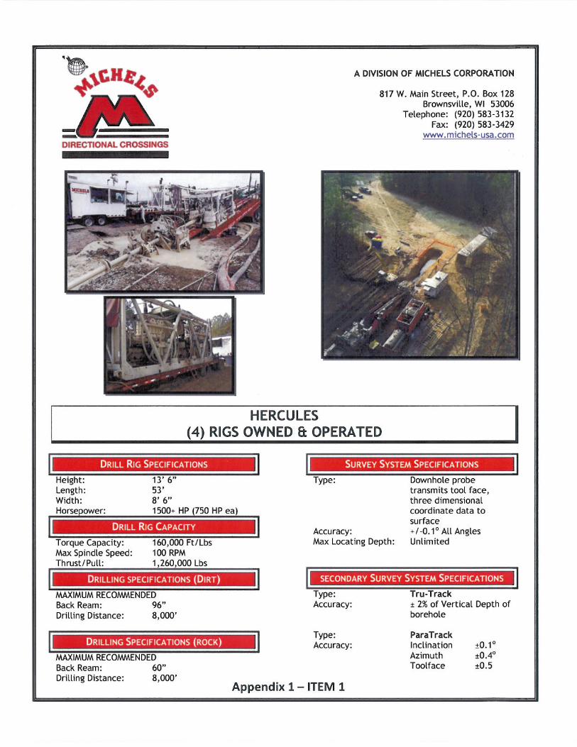
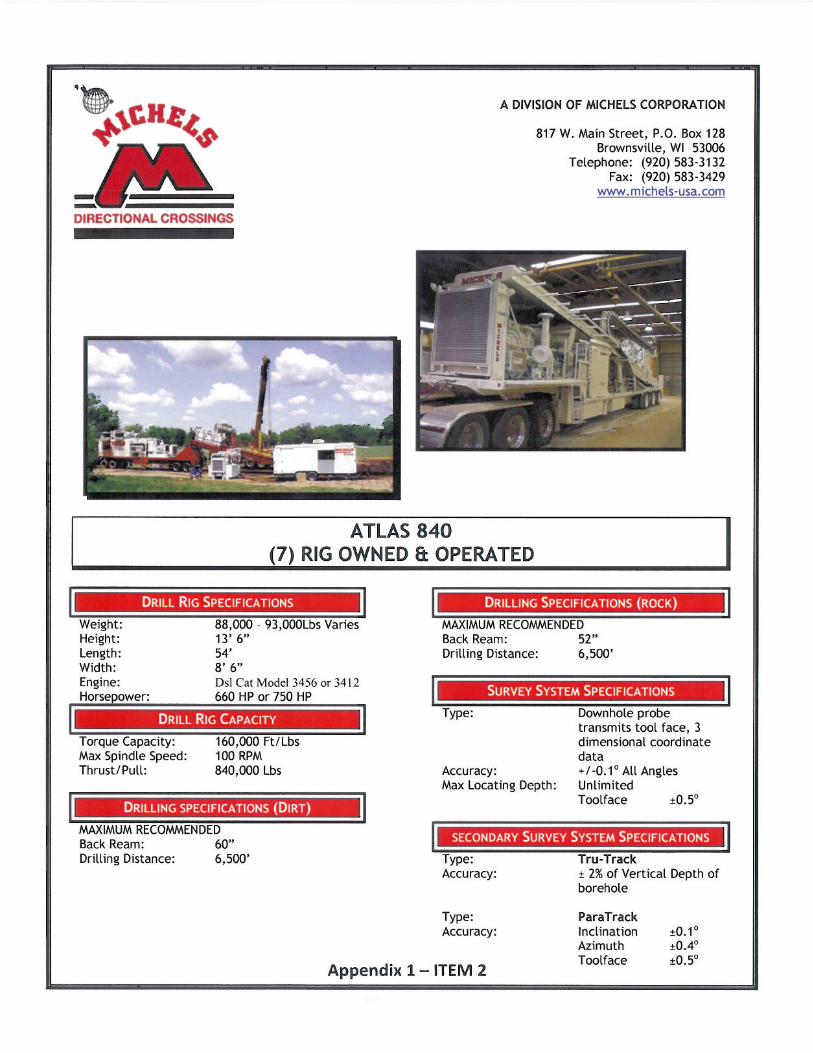
2.0 Drill rig specifications including push/pull force, torque and other specifications of the specific rig to be used on this project.
Either the Hercules Rig or Atlas 840 Rig or may be used depending on equipment availability. Both of these rigs are equally capable executing the St Clair River drill and pullback, with the Hercules having additional thrust and pull capability than required at this location. Specific information about these rigs is attached to the end of this appendix as ITEM 1 and ITEM 2.
3.0 A full description of the drilling fluid recycling system, fluid flow operating rate, tanks, pumps, solids control/recycling, centrifuge(s), etc.
See “Drill Mud Recycling System” paper in Appendix 3.
4.0 Proposed water supply for drilling.
Water will be purchased from the municipal water supplies of Marysville, Michigan and St Clair Township, Ontario by the contractor.
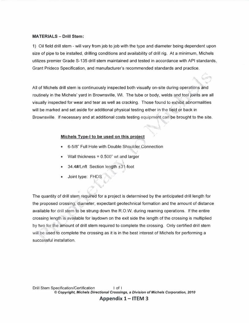
5.0 Drilling pipe description with certifications (size, grade and quantity).
See “MATERIALS‐ Drill Stem” information attached as ITEM 3 to the end of this appendix.
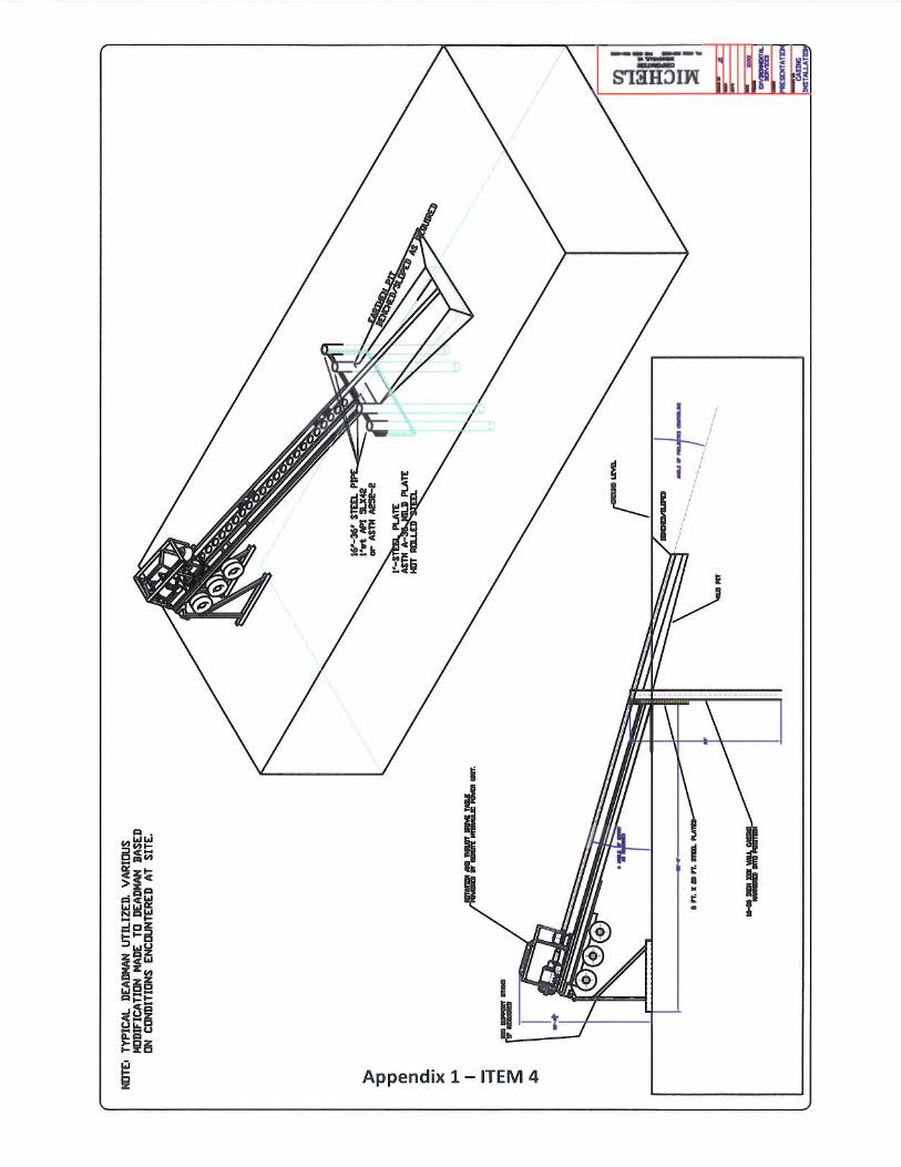
6.0 Details of drill rig anchoring system.
See drawing ITEM 4 attached to the end of this appendix showing the deadman anchoring system.
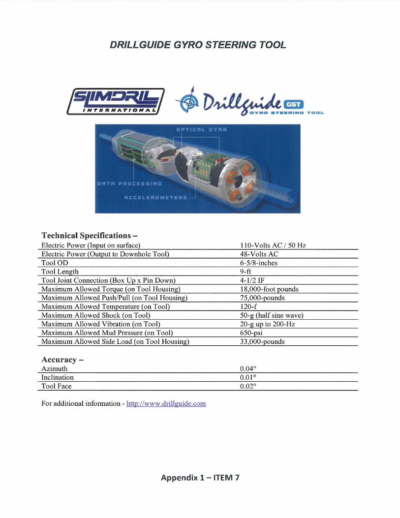
7.0 Proposed steering system with limitations and access requirements.
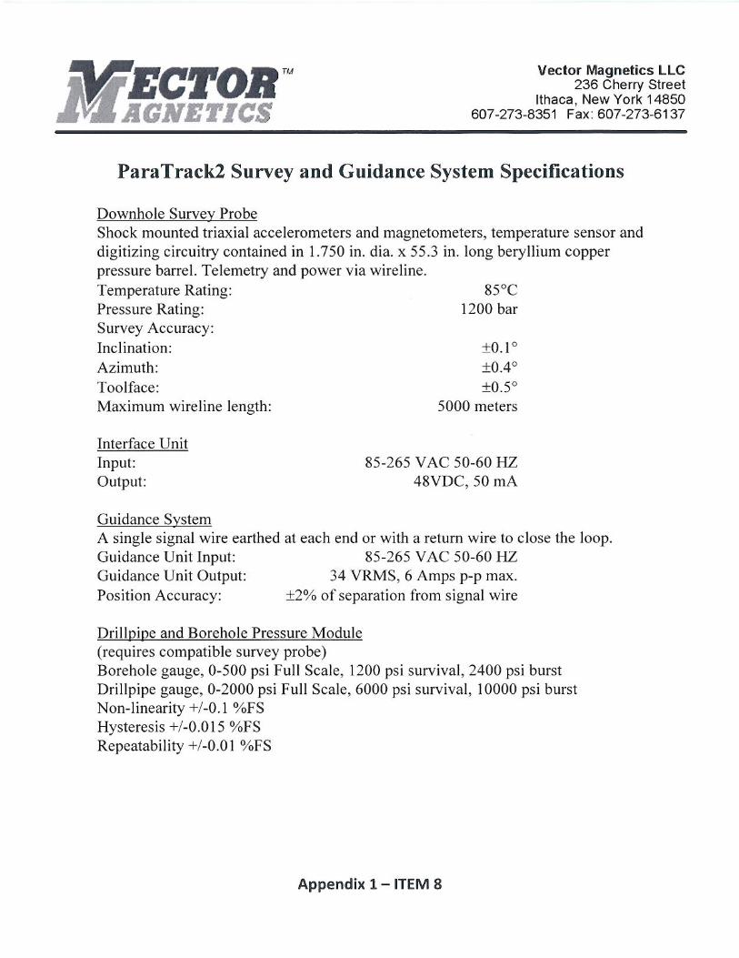
MGS or Gyro will be used in conjunction with ParaTrack2. See attachments at the end of this appendix pertaining to Steer Tool System ITEM 5, Magnetic Guidance System ITEM 6, Drillguide gyro steering tool ITEM 7, and ParaTrack2 ITEM 8.
8.0 Pressure monitor type and pressure range, if required.
See ParaTrack2 specifications, ITEM 8 attached to the end of this appendix.
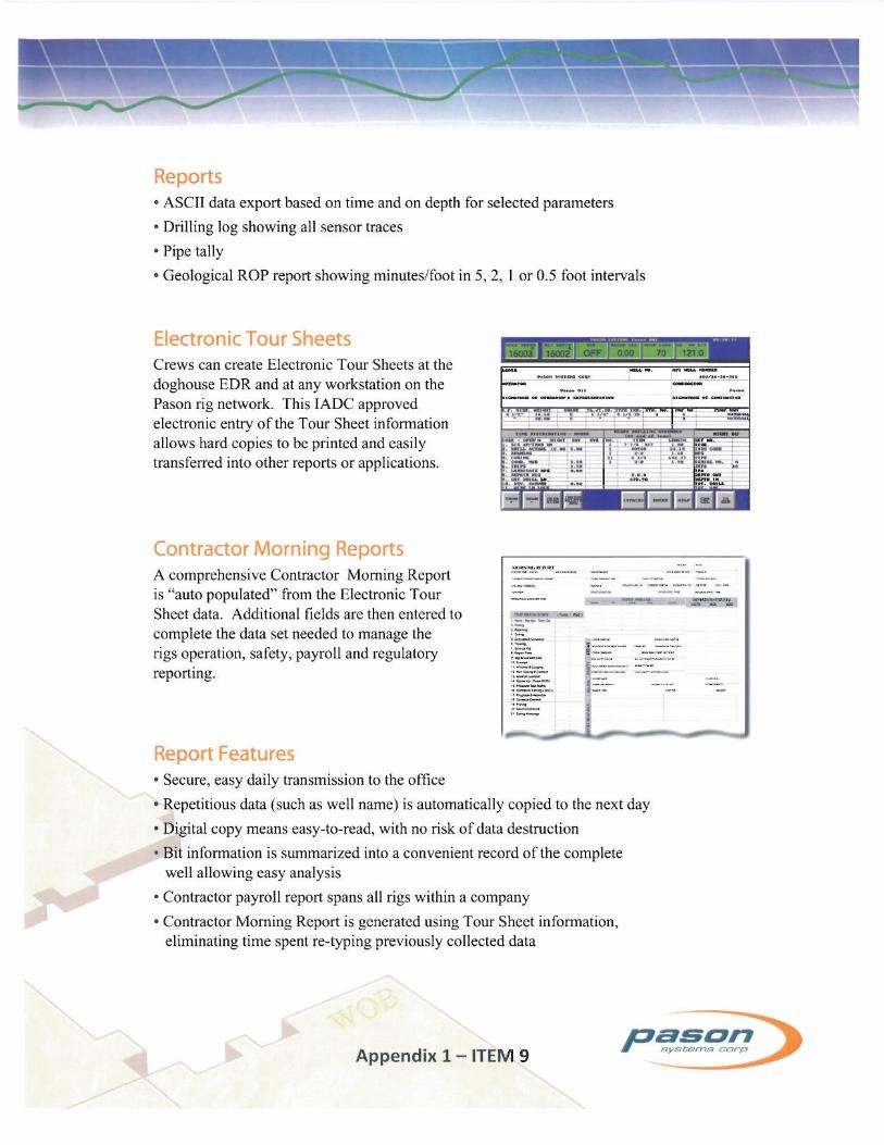
9.0 Electronic drilling recorder type and functions monitored (if required).
See EDR Brochure, ITEM 9 attached to the end of this appendix.
Contractor’s Drilling Execution Plan
APPENDIX 1 – Contractor’s Drilling Execution Plan Page 2
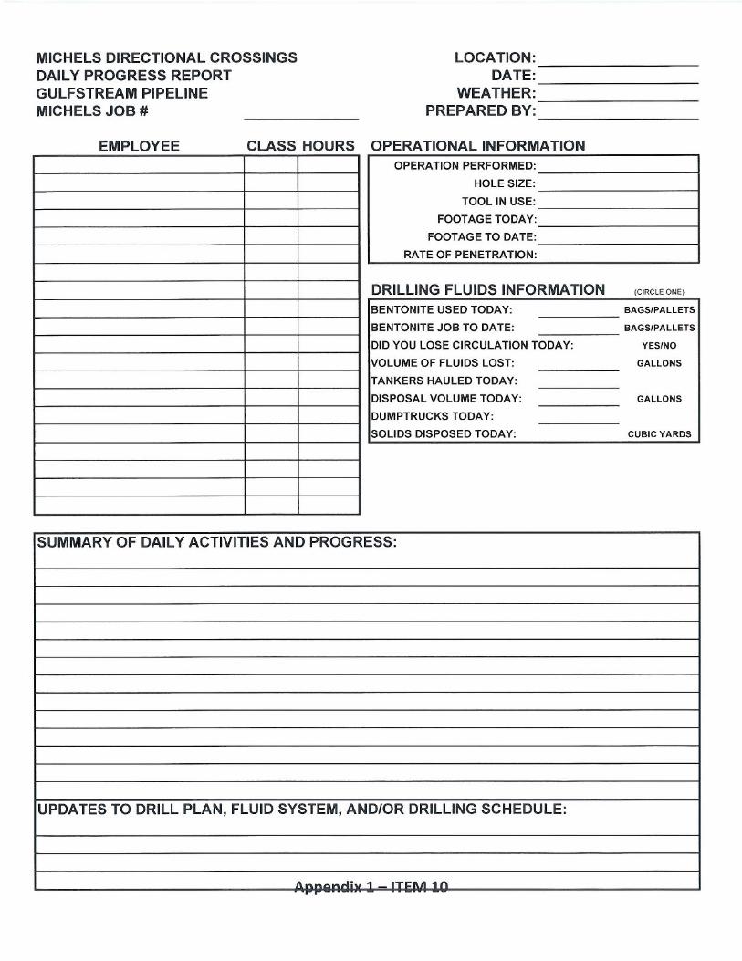
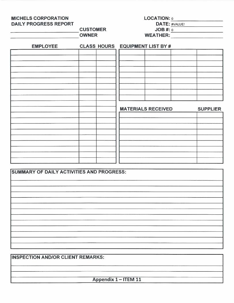
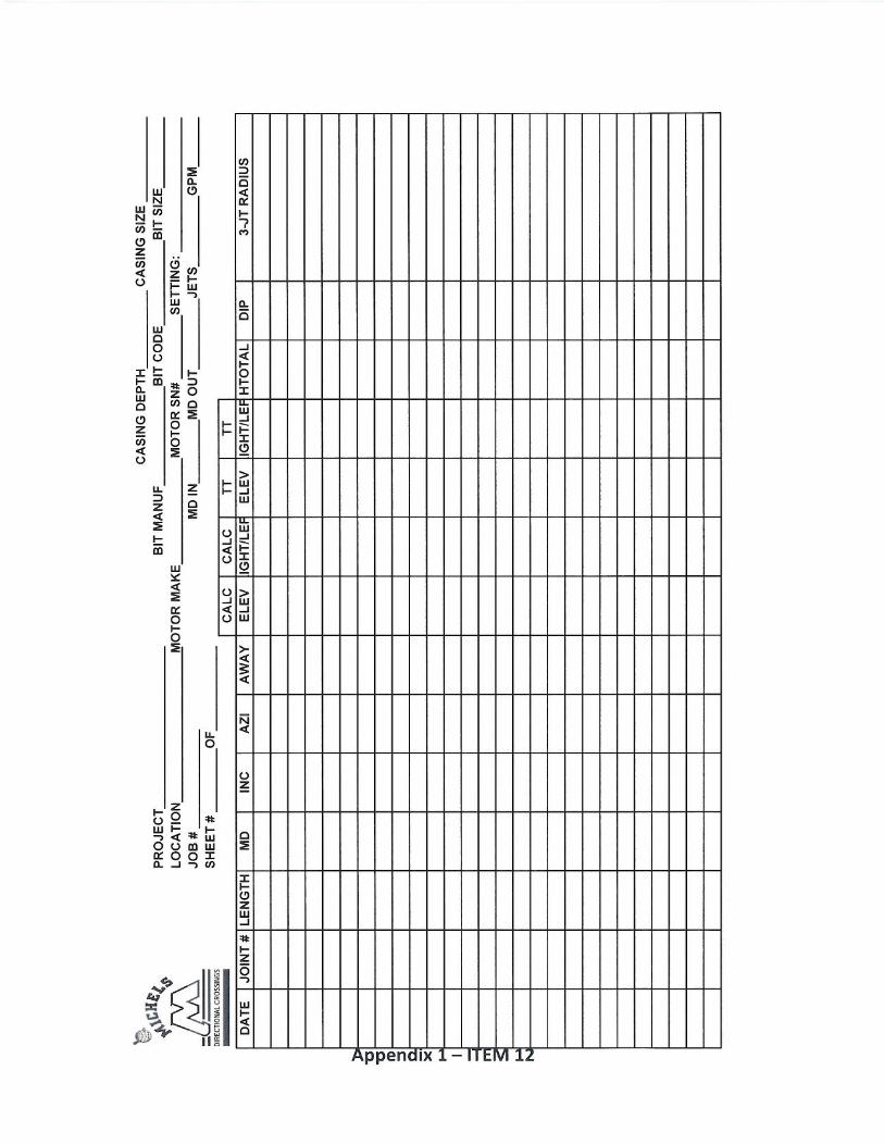
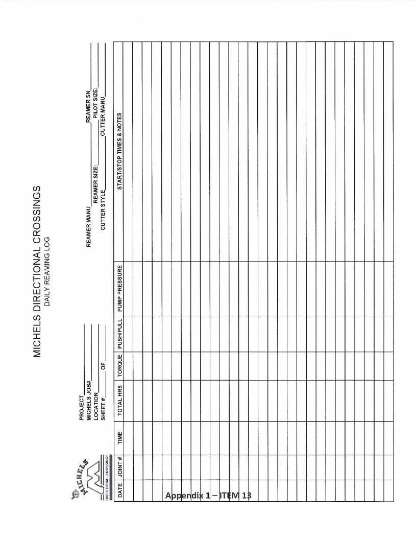
10.0 Sample of daily drilling reports.
See attached reports: 1) Daily Report ITEM 10, 2) DAILY PROGRESS ITEM 11, 3) DRILLSHEET ITEM 12, 4) REAMSHEET ITEM 13, and 5) Pullback Report ITEM 14.
11.0 Contingency plan to be employed in event of:
11.1 Casing removal difficulties.
Casing is not expected to be used on this project, unless there are guidance issues in the immediate vicinity of the HDD entry. If casing is installed and difficult to remove, the casing will be dug up and pulled until it comes free.
11.2 Inadvertent returns to surface.
See Inadvertent Return Plan (Appendix 2).
11.3 Equipment lost in the hole.
In the unlikely event of lost equipment downhole, the contractor will attempt to “fish out” the lost equipment by utilizing specialized tools designed to rethread the drill pipe onto the lost equipment. If this is not possible the contractor will deviate slightly from the designed drill path and drill around the lost equipment, with approval from Enbridge.
11.4 Hole collapse during pipe pull.
If the hole collapses during pipe pullback an assessment will be conducted by all parties involved and a determination will be agreed upon as to what direction should be taken. If the collapse is not too severe, assistance can be provided from the pipe side utilizing pneumatic assist or thrusting in order to complete the pullback. However, if the collapse is more severe than the pipe will be pulled out of the hole and a determination will be made whether the existing borehole can be re‐conditioned for pipe pullback. As a last resort the hole will be re‐drilled, from the opposite side if necessary.
11.5 Pipe getting stuck during pull back.
If the pipe becomes stuck during pullback, additional rotational and/or pulling force will be applied to un‐stick the pipe. If required, a pneumatic hammer or pipe thruster will be attached to the back of the pull string to help push the pull sting through the hole.
11.6 Appearance of severe damage to the coating during pullback.
The pipe coating will be inspected prior to installation and also holiday tested during pullback just prior to the downhole. ANY coating damaged during the pullback that can be safely exposed at the uphole (where the pipe is not too deep) will be repaired. In addition, Enbridge will verify that the cathodic protection system has adequate capacity to ensure the pipe is protected from corrosion.
11.7 Appearance of severe damage to the pipe during pullback.
The pipe is completely inspected prior to installation. If any severe damage is observed at the uphole after installation, an In‐Line Inspection tool will be sent through the pipe by Enbridge to verify the occurrence and severity of damage. An engineering decision will be made by Enbridge based on the In‐Line Inspection tool data.
12.0 A drilling fluid mitigation plan, including:
12.1 A description of the proposed fluid type and additives complete with manufacturer’s specifications (MSDS, etc.).

Contractor’s Drilling Execution Plan
APPENDIX 1 – Contractor’s Drilling Execution Plan Page 3
The possible bentonite drilling mud brands are:
Max Gel
Super‐Gel X
Quick‐Gel
Bara‐Kade
The possible additives (pending authorization from the appropriate agencies) are:
Suspend‐It
Drill‐Terge
InstaVis Plus
RelPac Xtra Low
Macro Fill
See the attachments to “Drill Mud Recycling System” paper in Appendix 3 for more information and the MSDS documents for these substances.
12.2 Written authorization from appropriate agencies to use additives, if required.
Enbridge will acquire written authorization from the appropriate agencies for the additives above prior to commencement of drilling.
12.3 Emergency response plan:
12.3.1 Notification procedures.
See Inadvertent Return Plan (Appendix 2).
12.3.2 Emergency containment and clean‐up procedures plan for inadvertent fluid migration or release in a water body or on land (including inadvertent returns).
See Inadvertent Return Plan (Appendix 2).
12.3.3 Emergency response equipment on site.
See Inadvertent Return Plan (Appendix 2).
13.0 A description of the fluid cleaning, recycling and control systems, including volumes of fluids and water tankage required.
See attachments to “Drill Mud Recycling System” paper in Appendix 3.
14.0 Disposal plan composed of:
14.1 An estimate of the complete composition of the drilling waste including the relative quantities of water, bentonite, other sediments and drill cuttings, and any additives which may be necessary during construction or to allow flocculation prior to.
The expected maximum material to dispose will consist of the following:
Cubic feet Cubic meters Material
16,935 479.5 Drill Cuttings
81,289 2,301.8 Water
3,387 95.9 Bentonite
<15 <0.4 Additives
101,625.80 2,877.72 Total
No flocculation material is expected to be used for disposal.

Contractor’s Drilling Execution Plan
APPENDIX 1 – Contractor’s Drilling Execution Plan Page 4
14.2 Method of containment and, if appropriate, disposal of drilling fluids onsite.
Drilling fluids will be contained in the drill hole sump or in frac tanks until shipment. Large open top dumpsters will be used to hold separated tailings from the mud unit.
14.3 Off‐site disposal plan (fluid disposal options).
The drilling mud is recycled many times and the tailings are separated by the mud unit. The tailings (and the drilling mud removed during swab and pullback) will be trucked to an environmentally approved gravel pit, farm field or landfill as fill material. Mud disposal locations will be identified, environmentally qualified and permitted in both Ontario and Michigan. It is expected that the majority of drilling mud and drill tailings will be disposed at a pre‐approved location in Michigan.