appearance capture and modeling of human teeth...appearance capture and modeling of human teeth...
TRANSCRIPT
Appearance Capture and Modeling of Human Teeth
ZDRAVKO VELINOV, Disney Research, Rheinische Friedrich-Wilhelms-Universität BonnMARIOS PAPAS, Disney ResearchDEREK BRADLEY, Disney ResearchPAULO GOTARDO, Disney ResearchPARSA MIRDEHGHAN, Disney ResearchSTEVE MARSCHNER, Cornell UniversityJAN NOVÁK, Disney ResearchTHABO BEELER, Disney Research
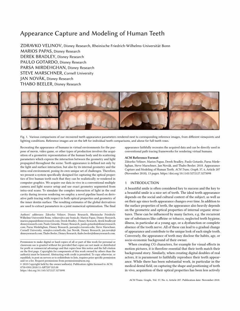
Fig. 1. Various comparisons of our recovered teeth appearance parameters rendered next to corresponding reference images, from different viewpoints andlighting conditions. Reference images are on the left for individual teeth comparisons, and above for full teeth rows.
Recreating the appearance of humans in virtual environments for the pur-pose of movie, video game, or other types of production involves the acqui-sition of a geometric representation of the human body and its scatteringparameters which express the interaction between the geometry and lightpropagated throughout the scene. Teeth appearance is defined not only bythe light and surface interaction, but also by its internal geometry and theintra-oral environment, posing its own unique set of challenges. Therefore,we present a system specifically designed for capturing the optical proper-ties of live human teeth such that they can be realistically re-rendered incomputer graphics. We acquire our data in vivo in a conventional multiplecamera and light source setup and use exact geometry segmented fromintra-oral scans. To simulate the complex interaction of light in the oralcavity during inverse rendering we employ a novel pipeline based on deriv-ative path tracing with respect to both optical properties and geometry ofthe inner dentin surface. The resulting estimates of the global derivativesare used to extract parameters in a joint numerical optimization. The final
Authors’ addresses: Zdravko Velinov, Disney Research, Rheinische Friedrich-Wilhelms-Universität Bonn, [email protected]; Marios Papas, Disney Research,[email protected]; Derek Bradley, Disney Research, [email protected]; Paulo Gotardo, Disney Research, [email protected]; Parsa Mirdehghan, Disney Research, [email protected]; Steve Marschner,Cornell University, [email protected]; Jan Novák, Disney Research, [email protected]; Thabo Beeler, Disney Research, [email protected].
Permission to make digital or hard copies of all or part of this work for personal orclassroom use is granted without fee provided that copies are not made or distributedfor profit or commercial advantage and that copies bear this notice and the full citationon the first page. Copyrights for components of this work owned by others than theauthor(s) must be honored. Abstracting with credit is permitted. To copy otherwise, orrepublish, to post on servers or to redistribute to lists, requires prior specific permissionand/or a fee. Request permissions from [email protected].© 2018 Copyright held by the owner/author(s). Publication rights licensed to ACM.0730-0301/2018/11-ART207 $15.00https://doi.org/10.1145/3272127.3275098
appearance faithfully recreates the acquired data and can be directly used inconventional path tracing frameworks for rendering virtual humans.
ACM Reference Format:Zdravko Velinov, Marios Papas, Derek Bradley, Paulo Gotardo, Parsa Mirde-hghan, Steve Marschner, Jan Novák, and Thabo Beeler. 2018. AppearanceCapture and Modeling of Human Teeth. ACM Trans. Graph. 37, 6, Article 207(November 2018), 13 pages. https://doi.org/10.1145/3272127.3275098
1 INTRODUCTIONA beautiful smile is often considered key to success and the key toa beautiful smile is a nice set of teeth. The ideal teeth appearancedepends on the social and cultural context of the subject, as well ason their age since teeth appearance changes over time. In addition tothe surface properties of teeth, the appearance also heavily dependson the geometric and optical properties of internal organic struc-tures. These can be influenced by many factors, e.g. the recurrentuse of substances like caffeine or tobacco, neglected teeth hygiene,illness, in particular at a young age, or a dysfunction or completeabsence of the tooth nerve. All of these can lead to a gradual changeof appearance and contribute to the unique look of each single tooth.Conversely, the appearance of teeth may disclose the habits, age, orsocio-economic background of their owner.When creating CG characters, for example for visual effects in
motion pictures, it is therefore essential that their teeth match theirbackground story. Similarly, when creating digital doubles of realactors, it is paramount to faithfully reproduce their teeth appear-ance. While there has been substantial work, in particular in themedical dental field, on capturing the shape and positioning of teethin vivo, acquisition of their optical properties has been less actively
ACM Trans. Graph., Vol. 37, No. 6, Article 207. Publication date: November 2018.

207:2 • Velinov, Papas, Bradley, Gotardo, Mirdehghan, Marschner, Novák, Beeler
Fig. 2. Dental scanning. Current dental scanners extract a diffuse texture.The diffuse albedo is incorrectly darker in the areas where the tooth isoptically thinner, and glossy highlights are also incorrectly encoded, leadingto brighter appearance than expected.
pursued. While the most recent intra-oral scanners do capture color,they offer only very basic appearance acquisition and do not ac-count for the complex optical properties of teeth, ending up withan overall unnatural look, as illustrated by the dental scan using a3Shape TRIOS® device shown in Fig. 2. Previous works dedicatedto capturing the reflectance of teeth limited themselves to simplemodels [Buchaillard et al. 2007] or derived synthetic models whichpartially approximate light transport [Larsen et al. 2012], in bothcases delivering lower visual quality compared to a more completelight transport simulation.The scattering properties of a tooth are determined by its two
outermost layers composed of materials with very different opticalproperties (Fig. 3). The inner core is made out of dentin, whichhas the biggest influence on its chroma and is also responsible forthe fluorescent nature of teeth. A layer of enamel with varyingthickness covers the dentin. It is typically thinner at the gums andthicker towards the tip, causing a chroma gradient. Enamel is astructurally dense material, but thinner than dentin. It has a highdegree of translucency, which depends substantially on its mineral-ization and hydration. At the microscopic level, enamel is formedby rods that run from the dentin towards the surface and causestrongly anisotropic light propagation. Translucent enamel displaysthe characteristics of opalescence, causing the tooth to backscat-ter in the blue spectra and hence appear red-yellowish when litfrom the other side. Finally, surface variations, cracks, stains andother imperfections add yet another layer of visual richness to teethappearance.
This work presents a step towards overcoming the limitations ofpresent acquisition systems by capturing the optical properties ofteeth such that they can be realistically re-rendered in virtual en-vironments. Our work complements existing shape reconstructionmethods, such as intra-oral scanning or extra-oral fitting. In factwe use geometry acquired through an intra-oral scan and segmentit according to Wu et al. [2016]. We acquire the appearance databy imaging a person’s mouth area from multiple views and undermultiple lighting conditions.To model the complex interaction of light within the oral cavity
and tooth volume, we use amodified path tracing framework capableof estimating derivatives with respect to optimized parameters whileperforming regular rendering. Essentially, our method iterativelysolves for the derivatives of the entire radiative transfer integral overthe entire visible scene. Furthermore, we can perform optimizationof not just scattering parameters (albedo, density, surface texture)but also geometric parameters (dentin surface shape). We modeldentin shape as a set of deformations from the base enamel shape,
Enamel
Crow
nRo
ot
Dentin
Tubules
Enamel RodsGingiva
a) b)
Fig. 3. Anatomy. a) A tooth is made of two different materials with verydifferent optical properties. The inner core is formed by dentin, which has thebiggest influence on the tooths chroma, and is covered by a layer of opticallydenser enamel. Finally, the tooth is bounded to the sides by gingiva tissue(gums), which scatters skin tinted light into the tooth. b) At a microscopiclevel, enamel is formed by rods that run from the dentin towards the surfaceand cause strong anisotropic light propagation.
which we parametrically control in the optimization loop. Thus weare able to predict the approximate shape and contribution of thehidden dentin surface on the appearance. Our approach represents astep forward in visual fidelity compared to previous works on toothappearance capture. To the best of our knowledge, the proposeduse of morphable shapes for representing hidden structures hasnot been explored by previous methods and represents a majorcontribution to the field of differentiable path tracing. We believethat our framework is general enough to be successfully employed inother applications, such as appearance acquisition of organic tissues(skin, fruits, plants), translucent gemstones, and other man-madeobjects.We validate our technique by capturing a dead tooth extracted
from a mouth cavity, where the ground truth inner dentin and outerenamel geometry is available. We further apply our method onin-vivo data acquired in an appearance capture session of humanvolunteers (Fig. 1). In both cases our approach closely recreates theoverall appearance. Since the main framework employed withinthe optimization loop is based on path tracing, the resulting set ofparameters is readily available for re-rendering the teeth with veryminor modification within production environments.
2 RELATED WORKIn the following we discuss other methods that capture properties ofteeth in the context of computer graphics and beyond. Our appear-ance capture approach is also related to methods for reconstructingthe appearance of real skin, in particular faces. Since the ultimategoal is to re-render the captured teeth in CG, we outline relevantwork in volumetric rendering, particularly those dedicated to teeth.Finally, as inverse rendering is a key ingredient to our optimizationpipeline, we end by discussing how this concept has been exploredin other contexts.
ACM Trans. Graph., Vol. 37, No. 6, Article 207. Publication date: November 2018.

Appearance Capture and Modeling of Human Teeth • 207:3
2.1 Teeth CaptureReconstructing the 3D shape of teeth is important in the field ofdentistry, in particular for diagnosing medical problems or planningrestoration procedures. Common approaches include plaster castingor CT scanning [Omachi et al. 2007; Yanagisawa et al. 2014]. Morelightweight intra-oral scanners have also been developed (e.g. 3MTM
True Definition, iTero, 3Shape TRIOS®, [Ahn et al. 2017]), whichtypically use structured light to recover teeth shape and, in some in-stances, a basic surface color. Detailed survey of these devices fromdental practitioner standpoint is provided by Mangano et al. [2017].In the areas of computer graphics and vision, photometric recon-struction methods such as shape-from-shading [Carter et al. 2010]and feature-based reconstruction [Zheng et al. 2011] have beenproposed. Because teeth generally have few identifiable features,model-based fitting approaches have gained popularity [Buchaillardet al. 2007; Farag et al. 2013; Mehl and Blanz 2005; Mostafa et al.2014]. The current state-of-the-art in teeth shape capture is the re-cent model-based method of Wu et al. [2016], who build a statisticalmodel of teeth shape from dental scans and then fit the model tosilhouette features, presenting high-quality results for teeth recon-struction from passive imagery. Most shape reconstruction paperslimit their appearance models to color extraction from images, as itis the case in Wu et al. [2016] and Kawai et al. [2014]. They are thusseverely limited in their ability to faithfully re-render teeth fromnovel viewpoints or in different lighting conditions. Our method fordetailed appearance capture of teeth would naturally complementthese techniques for teeth shape reconstruction.
In medical dental literature, several experiments have measuredappearance properties of teeth, in particular the scattering andabsorption values of both dentin and enamel [Fried et al. 1995; Pop-Ciutrila et al. 2015; Spitzer and Ten Bosch 1975]. These studies aremotivated by different applications in dentistry, for example thecreation of false teeth substitutes that are identical to real teeth [Pop-Ciutrila et al. 2015], or the study of how lasers designed for softtissue surgical procedures interact with hard dental tissue [Friedet al. 1995]. In all cases the measurement process is a destructive one,where individual teeth are sliced into thin layers for measurement. Inour work we design a method to measure the appearance propertiesof teeth in vivo, with the goal of re-rendering for computer graphics.The optical properties reported by dentistry literature, in particu-lar the average measured absorption and scattering properties ofenamel [Spitzer and Ten Bosch 1975] and dentin [Pop-Ciutrila et al.2015], are employed as initial values in our optimization procedure,described in Section 6.
To the best of our knowledge, the only existing specialized modelfor rendering teeth is presented by Larsen et al. [2012] which makesseveral compromises in order to enable real-time performance. Incontrast, we are interested in higher fidelity reproduction of the realteeth appearance for the application of high-quality digital humans.
2.2 Facial Appearance CaptureTeeth appearance capture can be considered part of the larger fieldof facial appearance modeling and capture, which has received alot of attention over the past decades. An in-depth overview canbe found in the state-of-the-art report of Klehm et al. [2015] and
is beyond the scope of this paper. The relevant work in the area offacial appearance capture is concerned with the estimation of scat-tering properties of skin, which falls in the wider area of volumetricappearance capture discussed in the next section.
2.3 Volumetric Appearance CaptureA number of methods have been proposed for acquiring surface-based definitions of translucency (e.g. the methods by Debevec et al.[2000]; Donner et al. [2008]; Tong et al. [2005]). We take a differentapproach and explicitly model the volumetric optical propertiesof teeth, which falls into the wider area of volumetric appearancecapture. The most common approach to estimate the absorption andreduced scattering coefficients is to inject light at a specific pointand image the diffusion profile on the medium. Approaches employsingle beams [Jensen et al. 2001; Weyrich et al. 2006], stripes [Tariqet al. 2006], and dots [Ghosh et al. 2008].Wang et al. [2008] employeda polygrid diffusion algorithm for solving the diffusion equation.Munoz et al. [2011] proposed a pipeline for predicting the appear-ance of optically thick homogenous translucent objects based onthe diffusion theory. Papas et al. [2013] measured a database ofdiffusion profiles of pigments used in a mixture estimation pipelinecapable of reproducing the appearance of translucent materials. Incontrast, Gkioulekas et al. [2013] invert the radiative transfer equa-tion [Chandrasekhar 1960] and solve in operator-centric fashion foroptical parameters using a combination of Monte Carlo rendering,stochastic gradient descent, and material dictionaries.
More generally our method builds upon the family of papers thatcompute analytic path contribution gradients which are numericallyintegrated on a sensor. Initially Hašan and Ramamoorthi [2013] pro-vided analytic gradients of paths with respect to albedo to facilitateinteractive albedo editing. This was later generalized to handle allBidirectional Scattering Distribution Function (BSDF) and volumerelated properties [Khungurn et al. 2015] and more general light-ing/viewing conditions [Gkioulekas et al. 2016] for the purpose ofinverse rendering. Our paper extends this line of work by allowingthe joint optimization of optical properties and geometry, which isessential for optimizing the dentin geometry in the case of teeth.
2.4 Rendering Translucent MaterialsThe concept of BSDFwas introduced in physics tomodel transparentsurfaces [Bartell et al. 1981; Dereniak et al. 1982]. In order to rendermaterials with a significant degree of internal scattering, Stam [1995]proposed a grid-based method for spatially resolving the diffusionof light. To render effects due to subsurface scattering, Jensen et al.[2001] utilized the diffusion dipole, which was later extended tohandle layered materials [Donner and Jensen 2005; Donner et al.2008] and edges and corners [Donner and Jensen 2008]. It wasdemonstrated that the quality of diffusion-based approaches can beimproved by quantization [d’Eon and Irving 2011] and combinationwith Monte Carlo simulations [Habel et al. 2013; Li et al. 2005].Frisvad et al. [2014] proposed a directional dipole that better handlestransport at oblique angles. Frederickx and Dutré [2017] introduceda forward scattering dipole model based on the theory of functionalintegrals for radiative transfer. Despite all of these improvements,
ACM Trans. Graph., Vol. 37, No. 6, Article 207. Publication date: November 2018.

207:4 • Velinov, Papas, Bradley, Gotardo, Mirdehghan, Marschner, Novák, Beeler
the poor handling of the boundary leads to inaccurate results whenthe object is thin and (locally) highly translucent, such as teeth.
Approaches based onMonte Carlo integration, such as volumetric(bidirectional) path tracing [Kajiya and Von Herzen 1984; Lafortuneand Willems 1996], metropolis light transport [Pauly et al. 2000],or photon mapping [Donner and Jensen 2008; Jensen and Chris-tensen 1998] are computationally more intensive, but provide high-accuracy results. Since we strive for visual fidelity and can affordrender times on the order of minutes, we use volumetric path tracingduring inverse rendering and to render our validation results.
3 METHOD OVERVIEWLight takes many paths when interacting with teeth. First, it inter-acts with the surface, characterized by a rough dielectric layer, and iseither reflected or refracted into the interior. The interactions in theinterior are mainly defined by the two layers of a tooth: enamel anddentin. We thus identify three sets of parameters defining the ap-pearance of teeth: surface reflectance and transmission, sub-surfacescattering parameters, and inner dentin shape. Our approach aimsto derive a plausible set of model parameters for the purpose ofhigh-quality rendering in a scenario where teeth are illuminatedexternally with respect to the oral cavity. We split our discussioninto a general definition of the appearance model in Section 4, ourdata acquisition methodology in Section 5, and the respective pa-rameter estimation pipeline in Section 6 followed by qualitativeevaluations of the proposed model and optimization on real-worldmeasurements in Section 7.
4 TEETH APPEARANCE MODELThe appearance of a tooth is highly influenced by the shape and op-tical properties of its enamel and dentin parts (Fig. 3). We representboth materials as bounded volumes and introduce a number of keysimplifying assumptions to accelerate the inverse rendering.
4.1 EnamelBoundary Geometry and BSDF. The enamel boundary is the outer
boundary of the tooth, and is modeled as a triangle mesh. In order tomodel the interaction of light with the air-enamel boundary, we usea modified version of the smooth-dielectric BSDF, which adopts theconcept of separating the air and enamel using a “thin” dielectriclayer.
The BSDF consists of a reflective and a transmissive component,f (x,ωi ,ωo ) = fr (x,ωi ,ωo ) + ft (x,ωi ,ωo ), where ωi and ωo corre-spond to the incident and outgoing light directions.The reflection component is defined in a standard way,
fr (x,ωi ,ωo ) =δ (ωh, n)|ωi · n|
F (ωi · n,η), (1)
where F is the Fresnel term that quantifies the amount of lightreflected off the dielectric boundary (see e.g. [Pharr et al. 2016] forthe definition), x is the spatial position, ωh is the half-way vectorbetween ωi and ωo , n is the surface normal, and δ (a,b) is a Diracdelta function that equals +∞ when a = b and 0 otherwise. We usea fixed refractive index from dentist literature η = 1.631 [Meng et al.2009] for computing the Fresnel term.
The transmission component,
ft (x,ωi ,ωo ) = at (x)δ (ωi ,−ωo )
|ωi · n|(1 − F (ωi · n,η)), (2)
introduces the simplification that transmitted light does not bend, i.e.it continues along a straight line, which greatly simplifies the light-transport simulation. The spatially varying at (x) modulates theabsorption of the thin enamel/air boundary layer. During inverserendering we store at (x) in a texture which is indexed by a UVparametrization of the outer enamel mesh.
The BSDF can be interpreted as an infinitesimally thin dielectriclayer, and, while physically inaccurate, the model is expressiveenough to capture specular highlights and stains, which are essentialto faithfully represent the appearance. Ignoring the bending oflight rays during transmission greatly accelerates our Monte Carlosimulations during inverse rendering as direct illumination canbe sampled using shadow rays that connect to lights through theboundary. We avoid highlights during optimization by maskingthem and reintroduce them in the final images by using a mixture ofthis BSDF representing the transmission term and a rough dielectricrepresenting the reflection term according to the GGX distribution[Walter et al. 2007].
Volumetric Properties. Once transmitted through the boundary,light will start interacting with the inner material. To model thepropagation through the volume, we rely on the radiative transferequation [Chandrasekhar 1960],
(ω · ∇L) = −σL(x,ω) + ασ∫
fp (ωi ,ωo )L(x,ωi )dωi , (3)
which describes the change of radiance L due to absorption andscattering, here quantified by the extinction coefficient σ and single-scattering albedo α . To reproduce the characteristic wavelength-dependent scattering and absorption of teeth, these quantities areRGB vector values.In order to model the directional distribution of scattered light,
we use a two-lobe phase function:
fp (ωi ,ωo ) = β fHG(ωi · ωo,д1) + (1 − β)fHG(ωi · ωo,д2), (4)
where β balances the influence of the two lobes and fHG is theHenyey-Greenstein [1941] phase function parameterized by themean cosine д of the scattering angle.
4.2 DentinBoundary Geometry and BSDF. The thickness of the enamel layer
largely affects the amount of light reaching the dentin core of thetooth and has therefore significant impact on the overall appearance.We allow varying the thickness by modeling the enamel-dentininterface using a blend-shapemodel defined by a set of deformations:
V = B0 + c · (B − B0)T. (5)
We denote the resulting shape V, its individual vertices vi , themeshes representing the deformation by each mode B, and thevector weights c. We chose to represent the deformations withrespect to an initial mesh B0 as it enables intuitive visualization ofeach mode. Through experimentation we came to the conclusionthat three modes are enough to capture most of the visible changesin scattering introduced by the difference of enamel thickness. The
ACM Trans. Graph., Vol. 37, No. 6, Article 207. Publication date: November 2018.

Appearance Capture and Modeling of Human Teeth • 207:5
(a) (b) (c) (d)
Fig. 4. Dentin deformation modes. The fully deformed (a) dentin blendshape of an incisor serves as a boundary defining enamel thickness. Foroptimization purposes it is further decomposed in three deformation modesalong the major axes extracted according to the canonical tooth space suchthat they represent the following directions: (a) buccal, (b) proximal, (c)occlusal.
modes represent the deformation along the three major axes in acanonical tooth space; see the illustration for a single tooth in Fig. 4.
We use a highly simplified BSDF to model the interactions of lightwith the enamel-dentin interface, which assumes an index-matchedboundary, i.e. light passes through the interface unaltered.
Volumetric Properties. The directional scattering is modeled anal-ogously to enamel, i.e. using a two-lobe phase function.
4.3 Gingiva and oral cavityGingiva or gums and the oral cavity in general do have an indirectimpact on the appearance of teeth since they scatter skin tintedlight into the tooth. In order to explain that stray light and preventthe optimization from predicting a tinted tooth we have to modeland include the gums and a substitute for the oral cavity walls.The gums are modeled as a triangle mesh wrapping around the
outer boundary of the root of the teeth. As we can directly observethe gums, we use the same set of parameters as the enamel toextract their appearance through numerical optimization with fixedrefractive index η = 1.33.
The oral cavity is highly occluded and non-trivial to capture, how-ever it has a great impact on the appearance as light bounces fromits walls and illuminates areas in shadow. We use a substitute meshwith a diffuse reflectance set as free parameter. Its starting point isderived by using similarity theory and average values derived fromprevious optimization of the scattering parameters of gingiva.
5 DATA ACQUISITIONWe fit our appearance model described in Section 4 to real teethmeasurements captured for three volunteers. In this section we de-scribe the data capture and the pre-processing and post-processingsteps.
5.1 Image CaptureIn order to obtain accurate appearance parameters, we require adense sampling of incoming and outgoing light directions. For thisreason, we capture each volunteer in a light dome [Beeler 2012]consisting of 155 lights (each one a RGB LED triplet), where eachlight is approximately one meter away from the teeth. Due to oc-clusions of the head, we record imagery for 54 of the lights, whichaccounts for all visible incoming directions. We capture multi-view
imagery from three color cameras (Ximea CB200CG), positionedaround the edge of the light dome with long lenses to maximizeteeth resolution, recording 20 megapixel images, synchronized withindividual light activations. Please refer to Fig. 5 (a) for an image ofthe light dome and example captured imagery.
Calibration. We geometrically calibrate the cameras using a pla-nar fiducial pattern [Garrido-Jurado et al. 2014]. The positions ofthe lights are measured using a Leica DISTOTM S910 laser distancemeasuring device, and then aligned to the camera coordinate sys-tem by imaging a mirror sphere. Color calibration is performed byrecording the X-Rite ColorChecker® chart with all lights turned onto extract corrective terms similar to Ilie and Welch [2005]. The indi-vidual light intensities are measured by recording a diffuse sphericalspectralon and considering it as ideal Lambertian surface. In orderto account for spurious incoming light, a black (no light) image isrecorded and subtracted from all measurements.
Volunteer Preparation. Recording the 54 light directions requiresapproximately 10-15 seconds, during which time the subject mustremain still. To facilitate this, we provide a stabilizing neck brace, ahead strap and a rigid object to bite on, which also helps to separatethe upper and lower teeth. To minimize occlusions by the face, weretract the lips and cheeks using an OptraGate lip retractor fromIvoclar Vivadent, often used in dentistry.
Post-Processing. Despite stabilizing the volunteer’s head duringacquisition, there is still a minimal amount of residual motion left,which we remove as a postprocessing step by aligning all framesto the first image using optical flow [Brox et al. 2004]. Our im-agery contains shadows cast by the lips and lip retractor, whichwill confuse the appearance optimization since we do not modelthe geometry of the face or the retractor. Additionally, we will notattempt to match specular highlights since we are more interestedin the volumetric light transport. Therefore, we manually mask theimagery to remove shadows, the gums and inner mouth and employthe method of Mallick et al. [2005] to automatically detect and maskspecular highlights, keeping only valid teeth pixels that will informthe optimization. These tasks do not form an integral part of ouralgorithm, and are easy to perform by non-experts. They could alsobe further automated for use in a production pipeline when thecomplete facial appearance and geometry is available.
a) b)
Fig. 5. Data Acquisition. (a) We capture the teeth from three viewpointsunder 54 different light directions using a light dome. Here we show threedifferent light directions for the frontal camera. (b) The teeth are scannedand we align the geometry to the imagery, in preparation for the appearanceoptimization.
ACM Trans. Graph., Vol. 37, No. 6, Article 207. Publication date: November 2018.

207:6 • Velinov, Papas, Bradley, Gotardo, Mirdehghan, Marschner, Novák, Beeler
5.2 Geometry CaptureThe captured imagery alone is not sufficient to perform appearanceoptimization, as we require knowledge of the teeth geometry aswell. While lightweight teeth reconstruction methods exist (e.g. Wuet al. [2016]), they fail to recover the accurate shape of the backside of the teeth and only hypothesize the teeth shape where imagecoverage is low. Since we need to evaluate volumetric light paths,we require accurate teeth boundaries on all sides. Therefore, weobtain a professional teeth scan for the volunteer using a 3ShapeTRIOS® intra-oral scanner. In order to segment the teeth in the scanand separate them from the gums we align template teeth meshesto the scan geometry using the semi-automatic template fittingapproach described inWu et al. [2016]. Since the appearance of teethis tightly coupled with the gums, we also model the gums geometryartistically based off the scans. Finally, we align the resulting per-tooth geometry and gums model to the camera coordinate frameby manually selecting a sparse set of corresponding landmarks andsolving for a rigid transformation (see Fig. 5 (b)).
The final result of the data acquisition is, per volunteer, a total of162 images (54 individual light directions for three views) maskedto identify valid teeth pixels, with precise teeth and gums geometryaligned to the imagery. Part of this dataset will be used in the modelparameter optimization method and for validation.
6 MODEL PARAMETER OPTIMIZATIONWe formulate the problem of extracting the parameters that de-scribe the appearance of teeth as a non-linear optimization problem.Assuming we haveM pixels in each of the rendered and objective im-ages, and a vector xwith P parameters to be optimized according to aloss function ρ(ψ ) : RM → R and a cost functionψ (x) : RP → RM ,we formally define the set of optimal parameters
x+ = argminx
ρ(ψ (x)). (6)
Since light transport in participating media is generally difficultto evaluate in closed form, the cost function cannot be computedanalytically. Instead, we take the route of differentiable path tracingby computing analytic derivatives associated with each light pathand accumulating them to compute approximate global derivativesto guide a nonlinear optimization algorithm, thus iteratively solvingEq. 6. Since the number of light paths is finite—we use 64 samplesper pixel—we obtain a noisy estimate of the true gradient. As such,we take the first-order stochastic gradient descend (SGD) approachproposed by Kingma and Ba [2014], which was demonstrated to besufficiently reliable for solving problems with such characteristics.A similar decision was made by Gkioulekas et al. [2016] who usedAdaDelta [Zeiler 2012] in their Monte Carlo based SGD approachfor inverse rendering of participating media.The derivative for each pixel with respect to a free parameter is
expressed starting from the loss function ρ(ψ ), then applying thechange according to image-reconstruction filter F used when sam-pling the camera pixel footprint, and finally applying the individualgradients ∇ψx according to the respective parameters,
∇ρ =dρdF
dFdψx
∇ψx. (7)
We accumulate the first order derivatives at each interaction witha medium, surface or shape containing free parameters separatelyby exploiting the generalized product rule. Furthermore, we assumea pinhole camera with box filtering function dependent only on thenumber of samples N and the L2 loss function, resulting in the finalequation:
∇ρ =1N(C −Cref) ·
( K∏i=0
ψ(i)x
) ( K∑i=0
∇ψ(i)x
ψ(i)x
)=
1N(C −Cref) · T
( K∑i=0
∇ψ(i)x
ψ(i)x
), (8)
where C and Cref are vectors holding linearized rendered and ref-erence RGB images, respectively, and N denotes the number ofsamples and K the maximum number of bounces. The completethroughput is expressed as a matrix T , thus separating the specificchange introduced by each interaction from the complete computa-tion of light propagation.Three groups of parameters are treated within our optimization
pipeline: the dentin shape as well as the surface and subsurfaceparameters of dentin, enamel, and gums. We discuss them in theirown separate sections and show them in Fig. 6. For the purpose ofoptimization we define the respective block of gradients
∇ψx = ∇ψB ∥ ∇ψσ ∥ ∇ψα ∥ ∇ψfp ∥ ∇ψf (9)
as the concatenation of the gradients w.r.t. the deformable dentinshapemodel (∇ψB ), volume extinction (∇ψσ ), single-scattering albedo(∇ψα ), the phase function (∇ψfp ), and the BSDF surface model (∇ψf ).The gradients of subsurface parameters (∇ψσ , ∇ψα , ∇ψfp ) are fur-ther composed of separate groups of RGB components associatedwith dentin and enamel.
atωi
ωo
c
αd, σd, βd, g0,d, g1,d
αe, σe, βe, g0,e, g1,e
Fig. 6. Model parameters. We jointly optimize surface absorption (at ),enamel scattering parameters (αe, σe, βe, д0,e, д1,e), optical and geometryparameters of dentin (αd, σd, βd, д0,d, д1,d, c). We further create a relationbetween enamel and dentin parameters by smoothing the border betweenmedia which establishes correlation between scattering and geometry pa-rameters.
ACM Trans. Graph., Vol. 37, No. 6, Article 207. Publication date: November 2018.

Appearance Capture and Modeling of Human Teeth • 207:7
6.1 Enamel and GumsEnamel and gums are treated similarly by the optimization as theyare both modeled to share the same types of optical properties suchas a homogeneous volume and an absorption layer. For brevity wediscuss the case of enamel. The gums are treated analogously. Theonly difference is that enamel encloses another internal volume(dentin) with free optical and geometrical properties.
Air-Enamel boundary. The BSDF model introduces a linear de-pendency on its transmissive absorption coefficient. Excluding thereflectance term, the derivative at each transmission is completelydefined by the light transport equation, which leads to a very simpleequation for the accumulated term:
∇ψ(i)f
ψ(i)f
=1at. (10)
Phase function. We use a dual-phase function leading to threesets of parameters with the following accumulated term:
∇ψfp
ψfp=
1fp (ωi ,ωo )
( dfpdд1
∥dfpdд2
∥dfpdβ
). (11)
We use a linear blend between the phase functions leading to thefollowing relation for the analytic gradient with respect to the blendfactor:
dfpdβ= fp (ωi · ωo,д1) − fp (ωi · ωo,д2). (12)
The derivative with respect to the mean cosine дj of the j-th lobe is
dfpdдj= −b(j)
(2дj
1 − д2j+
3дj + 3 cosθ1 + д2j + 2дj cosθ
)fHG(ωi ,ωo,дj ), where
(13)
b(j) =
{β, for j = 1,1 − β, for j = 2.
(14)
These derivatives need to be further modified to account for cor-relation with other parameters. We employ a blend shape modelto approximate the geometry of dentin. Due to discontinuity intro-duced between the two media by the mesh, we cannot computederivatives expressing correlation between scattering and geometryparameters in path space. To alleviate this issue we interpolate thephase function parameters of dentin and enamel according to asmooth function in spatial domain based on distance q to the dentinshape. We use a logistic sigmoid,
l =1
1 + e−q/s, (15)
dldq=
eq/s
s(1 + eq/s )2, (16)
where we define the spread factor s such that the major influence is1mm around the border. We use this weight to linearly interpolatebetween enamel and dentin phase function parameters,
βmix = βel + (1 − l)βd, (17)дmix = дel + (1 − l)дd. (18)
We are going to re-express the derivative according to phase functionparameters with respect to blend weights from the perspective of apoint inside enamel,
∇ψfp ,c
ψfp ,c=
1fp (ωi ,ωo )
(βmix(д0,e − д0,d)
dfpdд0,mix
+
(1 − βmix)(д1,e − д1,d)dfp
dд1,mix+
(βe − βd)(fHG(д0,e) − fHG(д1,e))) dldq
dqdc.
(19)
This relationship can be expressed symmetrically for dentin by ex-changing the respective mean cosine coefficients д. Both derivativeswith respect to enamel and dentin parameters are computed at thesame time by applying their respective weight l and (1 − l). Werefer to Appendix A for more details about the derivative accordingto distance and the dedicated Section 6.2 on dentin geometry forspecific details about transforming from derivative according todistance to derivative according to blend weights c.
Single-scattering albedo. Assuming a piece-wise constant medium,the light gets attenuated by the scattering coefficient σs = ασ . Thederivative is analogous to the one of the BSDF function, given as
∇ψ(i)α
ψ(i)α
=1α. (20)
Therefore the modified derivative can be expressed with respectto the the blend shape weights analogously to the phase functionparameters,
∇ψ(i)αmix,c
ψ(i)αmix,c
=1
αmix(αe − αd)
dldq
dqdc, (21)
The difference between the high albedo values is much larger,resulting in poor scaling of the problem. To alleviate this issue were-expressed the parameter in a dual domain, α = 1 − 10κ , and alterthe respective derivative,
∇ψ(i)ακ
ψ(i)ακ
=∇ψ
(i)αmix
ψ(i)αmix
10−κ log10. (22)
Extinction coefficient. The density (precisely the extinction coeffi-cient) acts on both transmission and scattering. In the simple caseof a homogeneous medium, the derivative depends on two terms.The first term (∇ψσ ,s/ψσ ,s ) stems from the scattering coefficientapplied at each scattering event. The second term accumulated overeach path segment (∇ψσ ,t /ψσ ,t ) derives from the Beer-Lambert lawand the path-length dependence. The collective derivative is
∇ψσψσ
=∇ψσ ,sψσ ,s
+∇ψσ ,tψσ ,t
=Ns − 1σ
−
Ns∑k=0
tk , (23)
where Ns is the number of path segments and tk is the length ofthe k-th path segment. We further reparameterize in a dual domain,
ACM Trans. Graph., Vol. 37, No. 6, Article 207. Publication date: November 2018.

207:8 • Velinov, Papas, Bradley, Gotardo, Mirdehghan, Marschner, Novák, Beeler
σ = eξ , yielding
∇ψξ
ψξ= eξ
(Ns − 1σ
−
Ns∑k=0
tk
). (24)
6.2 DentinSimilarly to the enamel and the gums we optimize the phase func-tion, density, and albedo for dentin.We also leverage the blend shapemodel described in Section 4.2 to enable optimizing the geometryof dentin, which has a crucial impact on the appearance.
Dentin geometry. Modeling deformable surfaces within the con-text of differentiable path tracing requires the exact computationof analytic gradients to establish the connection between defor-mation parameters and the effect on light transmittance throughparticipating medium. We are going to discuss the specific caseof index-matched boundary between two homogeneous partici-pating media. The transmittance in this case is a composition ofthree operations: deformation (ψG), intersection distance (ψd ), andtransmittance (ψt ). Collectively, this subset of the light transportevaluation can be expressed as function composition,
ψB (c) = (ψt ◦ψd ◦ψG)(c). (25)
We will break down the set of operations, starting from the verylast one and build the respective transformations required to reachthe final solution. We express the deformation model as alreadydescribed in Eq. (5). To simplify the application of the chain ruleagainst the derivative of the per triangle intersection we are goingto restructure the matrix of vertices v(m) = [v(m)
0 v(m)
1 v(m)
2 ] intoa tensor of vertex triplets associated with each ray intersectionG = [v(0) . . . v(n)], with n being the number of intersections. Thechange according to the model parameters c = [c0 . . . ck ], whichare k in total, in this case is expressed by the change of shape∇ψG : Rk → Rk×n×3×3 derived from Eq. (5) as
∇ψG = B − B0 = ∆B. (26)
The next relation that is crucial to derive is the change of inter-section distance w.r.t. the model. It is governed by the ray-triangleintersection. The intersection point p(m)
r is expressed as a the dis-tance t (m) traversed along the ray in direction rd starting from pointro :
p(m)r = ro + rd t
(m), (27)
t (m) =
�������v(m)
2 − v(m)
0ro − v(m)
0v(m)
1 − v(m)
0
��������������v(m)
1 − v(m)
0rd
v(m)
2 − v(m)
0
�������−1
= |D1 | |D2 |−1. (28)
The transformation to distance space involves the computation of aJacobian matrix which represents a linear transformation such that∇ψd : Rk×n×3×3 → Rk×n .For convenience we define the vector columns of the adjugate
matrix as h(k )m ≡ colm adj(Dk ). By using the definition of the de-rivative of a determinant we express the columns of the Jacobian
S e S i S e S i
∆ BB
a) b)
Fig. 7. A path segment going from one medium into another will be influ-enced when changing the shape B as it will pass more through one of themedia and less through the other.
(∇ψ (m)
d ≡ colm∇ψd ) with the following relation:
∇ψ(m)
d = t (m)
−h(1)0 − h(1)1 − h(1)2
h(1)2h(1)0
−t (m)
|D2 |
−h(2)0 − h(2)2
h(2)0h(2)2
. (29)
The final part is computing the transformation to transmittancespace. As outlined in Fig. 7 the goal is to compute the effect a changeof shape∆B has on the light transport along a segment t . Lets assumethe segment crosses a boundary, exiting from a set of media whoseoptical properties are given by Se and entering into another onecharacterized by Si . Then the transmittance at the border (excludingthe endpoints) is expressed as
ψt = exp ((Si − Se ) · t) , (30)
where S = [σ1 . . . σn ] is a vector of the extinction coefficients whichis further split into a vector of entered (Si ) and exited media (Se ).These coefficients are appended to Si and Se at each successive cross-ing between media. The Jacobian transformation ∇ψt : Rk×n → Rk
is
∇ψt = (Si − Se ) exp((Si − Se ) · t). (31)
We are now able to express the entire computation of the accumu-lated term by also taking into account the common terms with thecomplete light transport:
∇ψB (c)ψB (c)
=1
ψB (c)∇ψt ∇ψd ∇ψG = (Si − Se ) ∇ψd ∇ψG. (32)
This relation shows thatwhen entering an optically thickermediumwith triangles translated in the positive direction w.r.t. to the ray di-rection, the transmittance increases as the ray traverses less distancethrough the medium with higher extinction (Fig. 7).
7 RESULTSWe implemented the optimization procedure in Python by usingthe scientific computing package Numpy as a building block of ourcustom implementation of Adam. We implemented custom volumet-ric integrator in Mitsuba [Jakob 2010] which enabled path tracingof derivatives with respect to the optimized parameters and devel-oped the respective BSDF, blend shape and data structures usedto store the parameters. We used the Python bindings to interfacewith the renderer and exchange free parameters x, the resultingderivative blocks ∇ψx, and rendered image C . We split derivativeestimation and image rendering in two independently seeded ren-dering passes. Our optimization and rendering runs on a dual CPUmachine equipped with Intel Xeon E5-2680v3 processors. We run
ACM Trans. Graph., Vol. 37, No. 6, Article 207. Publication date: November 2018.

Appearance Capture and Modeling of Human Teeth • 207:9
the optimization at very low resolution (approximately a fifth of thecaptured resolution across each dimension) to keep the executiontimes feasible.We setup the virtual optimization scene based on calibration
data of teeth geometry, camera, and light positions and optimizeagainst our stabilized images. We associate free parameters withthe appearance properties of all objects in the scene: teeth, gin-giva and oral cavity. We use a point light representation and therecovered positions to simulate our calibrated LED light sources.For the case of a single tooth scene we derive the volume parame-ters starting point by densely exploring the space spanned by thevalues reported in literature [Fried et al. 1995; Pop-Ciutrila et al.2015; Spitzer and Ten Bosch 1975] for both dentin and enamel andcomparing the rendered results with our reference measurements.This step is necessary since there is a wide range of values reportedin literature mainly due to the various pre-processing proceduresperformed on the measured sample surfaces which affect roughnessand consecutively the appearance. We tabulated the three dimen-sional domain of albedo, density, and phase function anisotropyinto a set of 50000 points and evaluated a scale invariant error ofa virtual homogeneous tooth against reference measurements of amasked tooth illuminated from various directions and viewed bydifferent cameras. For each channel we find the point in the domainwith the smallest error and use it as our initialization. We do notperform highlight or high frequency normal map fitting. For thecase of a complete set of teeth we initialize the appearance of allteeth with the converged values derived by the stochastic singletooth optimization.
We first explore the capability of our technique to estimate scatter-ing parameters of teeth and re-render them in virtual environmentsby using isolated dead teeth. We acquired micro-CT scans to extractthe exact geometry of enamel and dentin. We only mask highlightsfor this scene since the tooth is static. In Fig. 8 we provide quali-tative comparisons of our training set for a single view (left) andadditional extrapolated appearance renderings (middle, right) ona testing set with novel viewpoints corresponding to images cap-tured by other cameras but were not visible to the optimization.The procedure is initialized with average values derived from thedental literature. Overall our method provides plausible fits in thecase of an isolated dead tooth. Dead teeth contain details whichare less pronounced in live teeth. One example is dead tissue andcracks which cast volumetric shadows within the tooth volume thatour model does not explicitly support. Other discrepancies in thehighlights are caused by the reflection of the metal frame of ourdome. These preliminary results validated the plausibility of ourtechnique to estimate parameters of live teeth.We proceed with capture of live teeth in vivo of a few human
volunteers. We provide separate fits by progressively enabling moreparameters as shown in Fig. 9. Optimizing with a homogeneousenamel-only volume results in very smooth appearance which lacksdetail. To capture the translucency of teeth around the edges weadd an inner layer to model dentin. Finally, we model the missingsurface details by enabling a textured stains-absorption layer onthe enamel outer boundary. We provide the complete comparisonof fitting results in Fig. 10, including validation from novel view-points and reference images. Overall our method is able to match
Ref
Front CameraFront Lights
Front CameraSide Lights
Side CameraFront Lights
RefFit Fit Ref FitInit
Fig. 8. Dead Tooth Validation. We validate our appearance estimationfit on a dead incisor with known dentin geometry. Left: 9 light directionsfrom front (top to bottom) are shown from the front camera. We optimizethe appearance using the 9 references images as targets, initialized withdefault appearance parameters as shown. Our fit result closely matchesthe reference images. Center: Extrapolating the fit parameters to a sideview validates that the volumetric appearance is reasonably close to thereal tooth. Right: We extrapolate further to 9 different side light directions,as seen from the front camera view.
the appearance characteristics of a live tooth. Note that when asample location is masked from the camera then the optimizationmight arrive to sub-optimal results (due to over-fitting), such as therecovered diffuse albedo of the mouth.
The results of our method on the more challenging complete setsof teeth are shown in Fig. 11, Fig. 12, Fig. 13 on three different vol-unteers. Additional data regarding the initialization values, textures,masks and loss function values is provided in the supplementalmaterial. All scenes use independent parameters for each tooth thatare jointly optimized. With these scenes we test the capability of ourmodel to capture realistic teeth appearance in the presence of gumsand inter-reflections from neighboring teeth. We would like to pointout that the measurements with the left camera shown in Fig. 13were not used in the optimization. Our model is optimized using
ACM Trans. Graph., Vol. 37, No. 6, Article 207. Publication date: November 2018.

207:10 • Velinov, Papas, Bradley, Gotardo, Mirdehghan, Marschner, Novák, Beeler
only the information of center and right cameras. The left cameracomparison is an evaluation of the ability of our method to extrapo-late to novel view points. Overall our method performs better forteeth in the front part of the mouth where shadows from the oralcavity occur less frequently than the teeth in the back. In the caseof a shadow boundary in our measurements we mask the nearbyaffected teeth since we do not have an accurate reconstruction ofthe oral cavity and thus we can not simulate the shadow accurately.Most of the molars are usually masked out in our measurementsand consequently some of them have false appearance. An accuratereconstruction of the entire oral cavity and the lip retractor mightbe required to achieve better fits on these particular teeth alongwith a regularization term. Regularizing the optical properties ofthese teeth to the average values of the frontal teeth is one optionthat we tested and partially alleviates the issue. We note that theun-textured reflectance of the oral cavity proxy in this case reachesa compromise between the inner color and the white lip retractor,resulting in ambient illumination which is specularly reflected bysome teeth in shadowed areas. The ambient light reflected by theoutside environment and light dome is not modeled, similarly tothe single tooth experiment. It leads to further discrepancies withthe real physical properties that are encoded in the current set ofparameters (optical thickness and texture). Capturing a light probealong with the actor can be used in the future to account for themissing light. We experimented with different loss functions (L1,relative L1, L2, relative L2) and came to the conclusion that L2 lossfunction produces higher quality results as it applies a significantlylower weight on dark and shadowed regions where most of the errordue to our measurement methodology is concentrated.
ReferenceEnamel+Dentin+TexEnamel+DentinEnamel Only
Fig. 9. Model Validation. All three components of our appearance modelare required to generate realistic teeth appearance. Fitting only a singlehomogeneous enamel volume appears too opaque (left). Fitting both enameland our dentin layer allows spatially-varying translucency (left-center).Adding a stain texture layer on top provides the best fit (right-center) to thereference image (right).
8 DISCUSSION AND FUTURE WORKWe presented a system for capturing bulk properties that are key fordigitally reproducing the appearance of teeth. Our approach is thefirst to consider the internal structure of each tooth when reverse-engineering its optical properties and while the results match thephotographs well, we would like to point out a number of limitationsof our system and how they could be addressed in future work.Our acquisition setup is very similar to those used for facial-
appearance capture, so suitable measurements could likely be madewith capture rigs already used in industry. Furthermore, a dense
Optimized Fit ValidationLeft Cam
Ref Fit Ref Render Ref RenderRef Fit Ref Fit
Center Cam Right Cam Right CamLeft Cam
Fig. 10. Single Tooth Fitting and Validation. Here we show the accuracyof our method on a single tooth. Left: The optimized appearance fit to threecameras (columns) and five lighting conditions (rows). Our fit tooth appear-ance closely matches the reference photo. Right: We validate the recoveredappearance properties by rendering under five new lighting directions thatwere not part of the optimization. Our model extrapolates well to theseunseen conditions.
capture setup is actually not required, as Fig. 10 shows an optimizedfit using only 3 cameras and 5 light sources.Our parametric model currently does allow for capturing craze
lines and cracks in enamel, and assumes the tooth is free of cavi-ties and fillings. These can potentially impact the appearance (e.g.amalgam fillings tend to significantly darken the entire tooth whichcan be observed on the right molar in Fig. 13) but we believe theyneed to be encoded in the geometric representation of the tooth andwould require a joint optimization of the appearance and the outertooth geometry. Such optimization is significantly more challengingthan inferring the outer geometry and appearance independently.Another option is to consider dental filling and cracks as a mor-phable mesh similarly to the dentin inner shape and perform jointoptimization in similar manner. In this work, we focused on makingthe first step towards capturing the appearance parameters and thedentin geometry, but we believe the joint optimization representsan interesting avenue for extending our work.
We heavily simplified the simulation of light transport at dielec-tric boundaries, completely disregarding the effect of light bendingupon refraction. While this purely performance-motivated simplifi-cation did not cause visually significant differences in our experi-ments, we would like to note that implementing search-based meth-ods [Holzschuch 2015; Walter et al. 2009] or manifold walks [Jakoband Marschner 2012] would permit simulating light transport moreaccurately at acceptable render times. We also did not attempt tocapture high-frequency glossy highlights. These could be added bysubtracting the main diffuse reflectance and performing standardBRDF fitting separately according to one of the existing techniquesin the graphics literature [Guarnera et al. 2016].The volumetric model can be further improved by considering
anisotropic particle distributions [Jakob et al. 2010] that would better
ACM Trans. Graph., Vol. 37, No. 6, Article 207. Publication date: November 2018.

Appearance Capture and Modeling of Human Teeth • 207:11
Left Cam Center Cam Right Cam
Ref Fit Ref Fit Ref Fit
Fig. 11. Upper Jaw Fitting: Volunteer 1. We compare the optimized result of our model and optimization on a complete upper jaw consisting of 14 teeth.We show three different viewpoints of the same person’s teeth next to corresponding reference images at the same resolution.
Left Cam Center Cam Right Cam
Ref Fit Ref Fit Ref Fit
Fig. 12. Upper Jaw Fitting: Volunteer 2. Fitting results on the entire upper jaw of another volunteer. We show three different viewpoints of the sameperson’s teeth and comparisons to corresponding reference images.
Left Cam Center Cam Right Cam
Ref Fit Ref Fit Ref Fit
Fig. 13. Upper Jaw Fitting: Volunteer 3. Fitting results on the entire upper jaw of another volunteer. In this experiment we only use the center and rightcameras during the optimization. The left camera image comparison is a qualitative, modeling power evaluation of our method when used to extrapolate tonovel views.
represent the tubular structure of enamel. Another option is to en-able heterogeneity and spatial variation of the scattering parametersof enamel and dentin. In this work, we opted for homogeneous ap-proximations with anisotropic phase functions to avoid excessivelylong rendering times. Another danger of adding more parametersto the model is over-fitting and it may require regularization andpriors to constrain the optimization. A careful analysis of potentialgains in visual fidelity is to be carried out first before committingto more sophisticated models; our experiments did not reveal such
needs but we did not attempt to model heavily stained and damagedteeth where additional parameters could potentially help.
The choice to use per-path analytic gradients for each parameterenables the cancellation or reuse of certain terms within the im-plementation. We further optimize the layout of the block-sparsegradients and avoid a significant amount of computation. Anotheralternative is to use automatic differentiation which would need tobe applied to a substantial part of the rendering system, including
ACM Trans. Graph., Vol. 37, No. 6, Article 207. Publication date: November 2018.

207:12 • Velinov, Papas, Bradley, Gotardo, Mirdehghan, Marschner, Novák, Beeler
the carefully optimized ray/triangle intersection code, potentiallyentailing additional performance and storage costs.
9 ACKNOWLEDGMENTSWe would like to thank Lifan Wu for the initial work on the differen-tiable integrator and numerical optimization pipeline. We thank Dr.med. dent. Lukas Stucky, Raphael Laue, Dr. med. dent. Sven Müh-lemann and the rest of the team at the Center of Dental Medicineat the University of Zurich for the intra-oral geometry scans. Fur-thermore, Dr. Klearchos Stylianides for many valuable discussionsregarding the anatomy and appearance of human teeth. In additionwe thank Gaspard Zoss and Jan Wezel for generously donating theirtime for the measurements required by this work.
REFERENCESJae Sung Ahn, Anjin Park, Ju Wan Kim, Byeong Ha Lee, and Joo Beom Eom. 2017.
Development of Three-Dimensional Dental Scanning Apparatus Using StructuredIllumination. In Sensors.
F. O. Bartell, E. L. Dereniak, and W. L. Wolfe. 1981. The theory and measurement ofbidirectional reflectance distribution function BRDF and bidirectional transmittancedistribution function BTDF. In Radiation scattering in optical systems, G. H. Hunt(Ed.), Vol. 257. 154–160. https://doi.org/10.1117/12.959611
Thabo Beeler. 2012. Passive Spatio-Temporal Geometry Reconstruction of Hu-man Faces at Very High Fidelity. Ph.D. Dissertation. ETH Zurich / Dis-ney Research Zurich. http://graphics.ethz.ch/~dbeeler/research/bee12c/PassiveSpatioTemporalGeometryReconstructionOfHumanFacesAtVeryHighFidelity.pdf
T. Brox, A. Bruhn, N. Papenberg, and J. Weickert. 2004. High accuracy optical flowestimation based on a theory for warping. In ECCV. 25–36.
Stéphanie I. Buchaillard, S. H. Ong, Yohan Payan, and Kelvin Foong. 2007. 3D StatisticalModels for Tooth Surface Reconstruction. Comput. Biol. Med. 37, 10 (2007), 1461–1471.
C.N. Carter, R.J. Pusateri, Dongqing Chen, A.H. Ahmed, and A.A. Farag. 2010. Shapefrom shading for hybrid surfaces as applied to tooth reconstruction. In IEEE ICIP.4049–4052.
S. Chandrasekhar. 1960. Radiative Transfer. Dover Publications.Paul Debevec, Tim Hawkins, Chris Tchou, Haarm-Pieter Duiker, Westley Sarokin, and
Mark Sagar. 2000. Acquiring the Reflectance Field of a Human Face. In Proceedingsof the 27th Annual Conference on Computer Graphics and Interactive Techniques(SIGGRAPH ’00). ACM Press/Addison-Wesley Publishing Co., New York, NY, USA,145–156. https://doi.org/10.1145/344779.344855
Eugene d’Eon and Geoffrey Irving. 2011. A quantized-diffusion model for renderingtranslucent materials. 30, 4 (July 2011), 56:1–56:14.
Eustace L. Dereniak, Langford G. Brod, and John E. Hubbs. 1982. Bidirectional trans-mittance distribution function measurements on ZnSe. Appl. Opt. 21, 24 (Dec 1982),4421–4425. https://doi.org/10.1364/AO.21.004421
Craig Donner and Henrik Wann Jensen. 2005. Light Diffusion in Multi-layered Translu-cent Materials. In ACM SIGGRAPH 2005 Papers (SIGGRAPH ’05). ACM, New York,NY, USA, 1032–1039. https://doi.org/10.1145/1186822.1073308
Craig Donner and Henrik Wann Jensen. 2008. Rendering Translucent Materials UsingPhoton Diffusion. In ACM SIGGRAPH 2008 Classes (SIGGRAPH ’08). ACM, New York,NY, USA, Article 4, 9 pages. https://doi.org/10.1145/1401132.1401138
Craig Donner, Tim Weyrich, Eugene d’Eon, Ravi Ramamoorthi, and SzymonRusinkiewicz. 2008. A Layered, Heterogeneous Reflectance Model for Acquiring andRendering Human Skin. In ACM SIGGRAPH Asia 2008 Papers (SIGGRAPH Asia ’08).ACM, New York, NY, USA, Article 140, 12 pages. https://doi.org/10.1145/1457515.1409093
David Eberly. 2015. Distance Between Point and Triangle in 3D. Technical Report.https://www.geometrictools.com/Documentation/DistancePoint3Triangle3.pdf
Aly Farag, Shireen Elhabian, Aly Abdelrehim, Wael Aboelmaaty, Allan Farman, andDavid Tasman. 2013. Model-Based Human Teeth Shape Recovery from a SingleOptical Image with Unknown Illumination. In Medical Computer Vision: RecognitionTechniques and Applications in Medical Imaging (MCV ’12). 263–272.
Roald Frederickx and Philip Dutré. 2017. A Forward Scattering Dipole Model from aFunctional Integral Approximation. ACM Trans. Graph. 36, 4, Article 109 (July 2017),13 pages. https://doi.org/10.1145/3072959.3073681
Daniel Fried, Richard E. Glena, John D. B. Featherstone, and Wolf Seka. 1995. Nature oflight scattering in dental enamel and dentin at visible and near-infrared wavelengths.Journal of Applied Optics 34, 7 (1995), 1278–1285.
Jeppe Revall Frisvad, Toshiya Hachisuka, and Thomas Kim Kjeldsen. 2014. DirectionalDipole Model for Subsurface Scattering. ACM Trans. Graph. 34, 1, Article 5 (Dec.
2014), 12 pages. https://doi.org/10.1145/2682629S. Garrido-Jurado, R. Mu noz Salinas, F.J. Madrid-Cuevas, and M.J. Marín-Jiménez.
2014. Automatic generation and detection of highly reliable fiducial markers underocclusion. Pattern Recognition 47, 6 (2014), 2280 – 2292. https://doi.org/10.1016/j.patcog.2014.01.005
Abhijeet Ghosh, Tim Hawkins, Pieter Peers, Sune Frederiksen, and Paul Debevec. 2008.Practical modeling and acquisition of layered facial reflectance. In ACM Transactionson Graphics (TOG), Vol. 27. ACM, 139.
Ioannis Gkioulekas, Anat Levin, and Todd Zickler. 2016. An Evaluation of Computa-tional Imaging Techniques for Heterogeneous Inverse Scattering. , 685-701 pages.
Ioannis Gkioulekas, Shuang Zhao, Kavita Bala, Todd Zickler, and Anat Levin. 2013.Inverse Volume Rendering with Material Dictionaries. ACM Trans. Graph. 32, 6,Article 162 (Nov. 2013), 13 pages. https://doi.org/10.1145/2508363.2508377
D. Guarnera, G.C. Guarnera, A. Ghosh, C. Denk, and M. Glencross. 2016. BRDF Rep-resentation and Acquisition. Comput. Graph. Forum 35, 2 (May 2016), 625–650.https://doi.org/10.1111/cgf.12867
Ralf Habel, Per H. Christensen, and Wojciech Jarosz. 2013. Photon Beam Diffusion: AHybrid Monte Carlo Method for Subsurface Scattering. 32, 4 (June 2013). https://doi.org/10.1111/cgf.12148
Milovš Hašan and Ravi Ramamoorthi. 2013. Interactive Albedo Editing in Path-tracedVolumetric Materials. ACM Trans. Graph. 32, 2, Article 11 (April 2013), 11 pages.https://doi.org/10.1145/2451236.2451237
L. G. Henyey and J. L. Greenstein. 1941. Diffuse radiation in the Galaxy. Astrophys. J.93 (1941), 70–83. https://doi.org/10.1086/144246
Nicolas Holzschuch. 2015. Accurate computation of single scattering in participatingmedia with refractive boundaries. Computer Graphics Forum 34, 6 (Sept. 2015), 48–59.https://doi.org/10.1111/cgf.12517
A. Ilie and G. Welch. 2005. Ensuring color consistency across multiple cameras. InTenth IEEE International Conference on Computer Vision (ICCV’05) Volume 1, Vol. 2.1268–1275 Vol. 2. https://doi.org/10.1109/ICCV.2005.88
Wenzel Jakob. 2010. Mitsuba renderer. http://mitsuba-renderer.org.Wenzel Jakob, Adam Arbree, Jonathan T. Moon, Kavita Bala, and Steve Marschner.
2010. A Radiative Transfer Framework for Rendering Materials with AnisotropicStructure. In ACM SIGGRAPH 2010 Papers (SIGGRAPH ’10). ACM, New York, NY,USA, Article 53, 13 pages. https://doi.org/10.1145/1833349.1778790
Wenzel Jakob and Steve Marschner. 2012. Manifold exploration: a Markov Chain MonteCarlo technique for rendering scenes with difficult specular transport. 31, 4 (July2012), 58:1–58:13.
HenrikWann Jensen and Per H. Christensen. 1998. Efficient simulation of light transportin scenes with participating media using photon maps. In 98 (Annual ConferenceSeries). ACM, New York, NY, USA, 311–320.
Henrik Wann Jensen, Stephen R Marschner, Marc Levoy, and Pat Hanrahan. 2001. Apractical model for subsurface light transport. In Proceedings of the 28th annualconference on Computer graphics and interactive techniques. ACM, 511–518.
James T. Kajiya and Brian P Von Herzen. 1984. Ray tracing volume densities. 18, 3 (Jan.1984), 165–174.
Masahide Kawai, Tomoyori Iwao, Akinobu Maejima, and Shigeo Morishima. 2014.Automatic Photorealistic 3D Inner Mouth Restoration from Frontal Images. , 51-62 pages.
Pramook Khungurn, Daniel Schroeder, Shuang Zhao, Kavita Bala, and Steve Marschner.2015. Matching Real Fabrics with Micro-Appearance Models. ACM Trans. Graph.35, 1, Article 1 (Dec. 2015), 26 pages. https://doi.org/10.1145/2818648
Diederik P. Kingma and Jimmy Ba. 2014. Adam: A Method for Stochastic Optimization.CoRR abs/1412.6980 (2014). http://arxiv.org/abs/1412.6980
Oliver Klehm, Fabrice Rousselle, Marios Papas, Derek Bradley, Christophe Hery, BerndBickel, Wojciech Jarosz, and Thabo Beeler. 2015. Recent Advances in Facial Appear-ance Capture. Comput. Graph. Forum 34, 2 (May 2015), 709–733.
Eric P. Lafortune and Yves D. Willems. 1996. Rendering participating media withbidirectional path tracing. Springer-Verlag, London, UK, 91–100.
Christian Thode Larsen, Jeppe Revall Frisvad, Peter Dahl Ejby Jensen, and JakobAndreasBærentzen. 2012. Real-Time Rendering of Teeth with No Preprocessing. In Advancesin Visual Computing, George Bebis, Richard Boyle, Bahram Parvin, Darko Koracin,Charless Fowlkes, Sen Wang, Min-Hyung Choi, Stephan Mantler, Jürgen Schulze,Daniel Acevedo, KlausMueller, andMichael Papka (Eds.). Springer Berlin Heidelberg,Berlin, Heidelberg, 334–345.
Hongsong Li, Fabio Pellacini, and Kenneth E. Torrance. 2005. A Hybrid Monte CarloMethod for Accurate and Efficient Subsurface Scattering. In Proceedings of theSixteenth Eurographics Conference on Rendering Techniques (EGSR ’05). EurographicsAssociation, Aire-la-Ville, Switzerland, Switzerland, 283–290. https://doi.org/10.2312/EGWR/EGSR05/283-290
Satya P Mallick, Todd E Zickler, David J Kriegman, and Peter N Belhumeur. 2005.Beyond Lambert: Reconstructing specular surfaces using color. In Computer Visionand Pattern Recognition, 2005. CVPR 2005. IEEE Computer Society Conference on, Vol. 2.Ieee, 619–626.
Francesco Guido Mangano, Andrea Gandolfi, Giuseppe Luongo, and Silvia Logozzo.2017. Intraoral scanners in dentistry: a review of the current literature. In BMC oral
ACM Trans. Graph., Vol. 37, No. 6, Article 207. Publication date: November 2018.

Appearance Capture and Modeling of Human Teeth • 207:13
health.Albert Mehl and Volker Blanz. 2005. A new approach for automatic reconstruction of
occlusal surfaces with the biogeneric tooth model. Int. J. Comput. Dent. 8 (2005),13–25.
Zhuo Meng, Steve Yao, Hui Yao, Yan Liang, Tiegen Liu, Yanni Li, Guanhua Wang,and Shoufeng Lan. 2009. Measurement of the refractive index of human teeth byoptical coherence tomography. Journal of Biomedical Optics 14 (2009), 14 – 14 – 4.https://doi.org/10.1117/1.3130322
E. Mostafa, S. Elhabian, A. Abdelrahim, S. Elshazly, and A. Farag. 2014. Statisticalmorphable model for human teeth restoration. In IEEE ICIP. 4285–4288.
Adolfo Munoz, Jose I. Echevarria, Francisco J. Seron, Jorge Lopez-Moreno, MashhudaGlencross, and Diego Gutierrez. 2011. BSSRDF Estimation from Single Images.Computer Graphics Forum 30, 2 (2011), 455–464. https://doi.org/10.1111/j.1467-8659.2011.01873.x arXiv:https://onlinelibrary.wiley.com/doi/pdf/10.1111/j.1467-8659.2011.01873.x
S. Omachi, K. Saito, H. Aso, S. Kasahara, S. Yamada, and K. Kimura. 2007. Tooth shapereconstruction from ct images using spline Curves. In Wavelet Analysis and PatternRecognition, Vol. 1. 393–396.
Marios Papas, Christian Regg, Wojciech Jarosz, Bernd Bickel, Philip Jackson, WojciechMatusik, Steve Marschner, and Markus Gross. 2013. Fabricating Translucent Materi-als Using Continuous Pigment Mixtures. ACM Trans. Graph. 32, 4, Article 146 (July2013), 12 pages. https://doi.org/10.1145/2461912.2461974
Mark Pauly, Thomas Kollig, and Alexander Keller. 2000. Metropolis light transport forparticipating media. Springer-Verlag, London, UK, 11–22.
Matt Pharr, Wenzel Jakob, and Greg Humphreys. 2016. Physically Based Rendering:From Theory to Implementation (3rd ed.). Morgan Kaufmann Publishers Inc., SanFrancisco, CA, USA.
Ioana-Sofia Pop-Ciutrila, Razvan Ghinea, Maria del Mar Perez Gomez, Horatiu Alexan-dru Colosi, Diana Dudea, and Mandra Badea. 2015. Dentine scattering, absorption,transmittance and light reflectivity in human incisors, canines and molars. Journalof Dentistry 43 (2015), 1116–1124.
D. Spitzer and J. J. Ten Bosch. 1975. The absorption and scattering of light in bovineand human dental enamel. Calcified Tissue Research 17, 2 (1975), 129–137.
Jos Stam. 1995. Multiple scattering as a diffusion process. (1995), 41–50.Sarah Tariq, Andrew Gardner, Ignacio Llamas, Andrew Jones, Paul Debevec, and Greg
Turk. 2006. Efficient estimation of spatially varying subsurface scattering parameters.Vision, Modeling, and Visualization (VMV2006) (2006), 129–136.
Xin Tong, Jiaping Wang, Stephen Lin, Baining Guo, and Heung-Yeung Shum. 2005.Modeling and Rendering of Quasi-homogeneous Materials. ACM Trans. Graph. 24,3 (July 2005), 1054–1061. https://doi.org/10.1145/1073204.1073311
Bruce Walter, Stephen R. Marschner, Hongsong Li, and Kenneth E. Torrance. 2007.Microfacet Models for Refraction Through Rough Surfaces. In Proceedings of the18th Eurographics Conference on Rendering Techniques (EGSR’07). EurographicsAssociation, Aire-la-Ville, Switzerland, Switzerland, 195–206. https://doi.org/10.2312/EGWR/EGSR07/195-206
BruceWalter, Shuang Zhao, Nicolas Holzschuch, and Kavita Bala. 2009. Single Scatteringin Refractive Media with Triangle Mesh Boundaries. ACM Transactions on Graphics28, 3 (Aug. 2009), 92:1–8. https://doi.org/10.1145/1531326.1531398
Jiaping Wang, Shuang Zhao, Xin Tong, Stephen Lin, Zhouchen Lin, Yue Dong, BainingGuo, and Heung-Yeung Shum. 2008. Modeling and Rendering of HeterogeneousTranslucent Materials Using the Diffusion Equation. ACM Trans. Graph. 27, 1, Article9 (March 2008), 18 pages. https://doi.org/10.1145/1330511.1330520
Tim Weyrich, Wojciech Matusik, Hanspeter Pfister, Bernd Bickel, Craig Donner, ChienTu, Janet McAndless, Jinho Lee, Addy Ngan, Henrik Wann Jensen, et al. 2006.Analysis of human faces using a measurement-based skin reflectance model. InACM Transactions on Graphics (TOG), Vol. 25. ACM, 1013–1024.
Chenglei Wu, Derek Bradley, Pablo Garrido, Michael Zollhöfer, Christian Theobalt,Markus Gross, and Thabo Beeler. 2016. Model-based Teeth Reconstruction. ACMTrans. Graph. 35, 6, Article 220 (2016), 220:1–220:13 pages.
R Yanagisawa, Y Sugaya, S Kasahara, and S Omachi. 2014. Tooth shape reconstruc-tion from dental CT images with the region-growing method. DentomaxillofacialRadiology 43, 6 (2014), 20140080.
M. D. Zeiler. 2012. ADADELTA: An Adaptive Learning Rate Method. ArXiv e-prints(Dec. 2012). arXiv:cs.LG/1212.5701
Shu-Xian Zheng, Jia Li, and Qing-Feng Sun. 2011. A Novel 3D Morphing Approach forTooth Occlusal Surface Reconstruction. Comput. Aided Des. 43, 3 (2011), 293–302.
A DERIVATIVE OF DISTANCE WITH RESPECT TOVERTEX TRANSLATION
Computing the derivative of distance to a point w.r.t. translationof individual vertices is essential when computing the contributionof spatially varying parameters defined by a blend shape model.We will consider these three primitives being closest to a point:
a point, an edge or a plane. These are three cases when comput-ing the distance between a point and a triangle according to themethod described by Eberly [2015]. Note that we are going to as-sume that within infinitesimal translations the closest primitivedoes not change.
Derivative of the distance w.r.t. a triangle vertex. The distance,
qps = |ps − v|, (33)
is defined by the spatial position of a point ps , and the closesttriangle vertex v. The derivative is computed by differentiatingaccording to each respective coordinate of the vertex and populatingthe respective column of the triangle derivative matrix dqps
dG ,
dqpsdv= −
ps − v|ps − v|
(34)
Derivative of the distance to a triangle edge. The distance to atriangle edge is expressed according to the vector orthogonal to theline and connecting the target point,
t =v1 − v0|v1 − v0 |
(35)
qps = (ps − v0) − t(t · (ps − v0)) (36)qps = |qps |, (37)
where we use the projection on the tangent t determined by thetwo vertices v0 and v1 to derive the final equation. Differentiatingthis equation is more involved and we provide just the final set ofequations for reference,
Av0 =
(t · (ps − v0)|v1 − v0 |qps
− 1)qps (38)
Av1 = −t · (ps − v0)|v1 − v0 |qps
qps . (39)
The individual derivatives according to each vertex (Av0 ,Av1 ) arefurther assigned to the correct corresponding columns in the trianglederivative matrix dqps
dG .
Derivative of the distance to a triangle interior plane. The distanceto a triangle interior point can be expressed by taking into accountthe normal vector n defined by the two edge vectors u0 = v1 − v0and u1 = v2 − v0,
n =u0 × u1|u0 × u1 |
,
and projecting the vector connecting a triangle vertex v0 and thetarget point ps ,
qps = n · (ps − v0). (40)
We are going to use the columns of the identity matrix Ii = coli I toderive a compact representation of the derivative,
Aki = −Ii × uk
Across =
A00 + A10 A01 + A11 A02 + A12−A00 −A01 −A02−A10 −A11 −A12
dq(i , j)ps
d(v0, v1, v2)= sgn(qps )A
(i , j)cross ·
((ps − v0) + qps
n|u0 × u1 |
). (41)
ACM Trans. Graph., Vol. 37, No. 6, Article 207. Publication date: November 2018.