app inventor tutorial 5 - mooreschools.com · app inventor tutorial 5 –shapesort this is an app...
TRANSCRIPT

1
App Inventor Tutorial 5 –ShapeSort
This is an app which will demonstrate the use of the image sprites used for drag and
drop objects on the screen.
What you will develop is a simple app where you must sort the shapes into the correct
‘box’.☺
Step 1: Open App Inventor
Once you have the App Inventor running type into your browser http://localhost:8888
Like the previous tutorials, create a new project.
Give the project the name – ShapeSort and click OK.

2
Step 2: Build the Interface of Shape Sort
The Shape Sort app needs many components. These include:
• A drawing canvas
• 5 image sprites
• A label
• A button
Let’s start by naming our application.
In the properties panel change the Title field of the screen to ShapeSort.
The Drawing Canvas component will allow us to identify locations around the screen for
‘dragging’. Place a drawing canvas component on the screen and change its properties
as follows:
Width – 300 pixels
Height – 350 pixels
Background Image – Browse and Select the image shape.png
Any object you want to drag around the screen must be held within this drawing canvas.
Objects that can be moved (dragged around) by the user are image sprites or a ball. The
ball can only be changed through its colour and radius properties. The image sprite
allows us to use our own image as the object. Both these animation objects are found
under the animation palette.

3
Select an image sprite and drag it onto the canvas along the top. We are adding five
objects so repeat this 4 more times. You will have 5 Image sprites, one for each object
we wish to sort (2 triangles, a circle, a square and a rectangle). Take each image sprite in
turn and change its properties as follows:
imagesprite 1 – Rename to shape1C (add C to allow us to identify the circle)
Picture – c1.png
imagesprite 2 – Rename to shape2S (add S to allow us to identify the square)
Picture – s1.png
imagesprite 3 – Rename to shape3T (T for triangle)
Picture – t1.png
imagesprite 4 – Rename to shape4T (triangle also)
Picture – t2.png
imagesprite 5 – Rename to shape5R (Rectangle)
Picture – tri.png
Your Shapes Sort display screen should now look like this....
One the user drags the objects into the boxes; we want to check to see if the location is
correct and also give feedback to the user. Let’s add a label and a button below our
canvas.
Drag over a label component – rename it to feedbackLbl
and change its text property to “Drag the shapes to the
correct box”
(From the properties you can change the width of the
label to ‘fill parent’ and centre the text if you wish)
Drag a button component below the label and rename
this checkBtn. (Again you may change the width to ‘fill
parent’ and can centre the button text.)

4
Step 3: Add the functionality to the Interface
Once the interface is ready we can set the functionality of the components. What we
want to happen can be described in the following steps:
1. The user touches any of the 5 objects along the top and can drag the object
around the screen
2. We check to see if the shapes are in the correct location.
3. The user clicks on ‘check shapes’ and
If they are in the correct box – we tell the user ‘well done’
If they are not in the correct box – we tell the user it is incorrect
The functionality of the program (step 3) is added by using the Blocks Editor - Open the
Blocks Editor to start adding code blocks.
This process may take a few minutes so please be patient ☺
Once the Blocks editor has loaded we want to add the code blocks for:
1. The user touches any of the 5 objects along the top and can drag the object
around the screen
Like the canvas component from the ‘PaintApp’ tutorial, an image sprite also has a block
for a dragged event, where it will move the object to the current location defined by the
user. From the ‘MyBlocks’ tab select the ‘shape1C’ option and drag over to the canvas
the ‘shape1C.Dragged’ code block. Again you will notice there are properties already
filled in. In our space we want to add the code block to move the object. Piece in the call
‘shape1C.MoveTo’ code block found under the ‘MyBlocks’ tab – ‘shape1C’.
This code block allows the ‘dragging’ of the image sprites. Repeat this code block for
shape2S, shape3T, shape4T and shape5R using the appropriate properties generated.
(Shape2S will need ‘currentX1’, ‘currentY1’ etc...).
Once you have these components completed – your blocks editor should look similar to
this....
The location of where we want the piece
to move to is defined by the current X/Y
location from the predefined properties.
We can access these properties by
selecting the ‘currentX’ property from the
‘My Definitions’. Similarly select the
‘currentY’ location and plug into the
shape1C.MoveTo block.

5
2. We check to see if the shapes are in the correct location.
In order to check to see if the shapes are in the correct location, we need to consider the
co-ordinates of the screen.
- Imagine our screen as a grid with co-ordinates like below...
This location would be (0, 0)
meaning its x value is 0 and its y
value is 0.
This location would be (7, 5)
meaning its x value is 7 and its y
value is 5.
x
y

6
Similar to this we must think of our drawing canvas interface as a coordinate system of
size 300 pixels by 350 pixels.
If we draw this out – we can identify the centre point of our
canvas is at location (150, 175)
Knowing this we can split our screen into the 4 locations (one
for circle, one for triangle, one for square and one for
rectangle). We can then make statements to identify the
locations.
Example.. If ‘objectA’ is somewhere in here we can say that the
‘ObjectA.X’ value is greater than (>) 150 and less than
(<) 300
‘ObjectA.Y’ value is greater than (>) 0 and less than
(<) 175
In our example for the Shape Sort app we also have an
image size to consider..
This image we put on the drawing canvas background
(shape.png) is 250 pixels by 250 pixels and is centred.
Considering the image (shape.png) on our drawing canvas we can now see a clear picture of the
location where each shape should be.

7
We can therefore also say that the xvalue > 25 and y value >50.
We have our coordinates for our triangle pieces.
Triangle piece x>25 and y >50 and x<150 and y <175.
Take the triangle (piece named shape3T and shape4T.
We can find its co-ordinates:
It is in the left side therefore xvalue < 150. It is in the upper half
therefore yvalue < 175.
The distance between the canvas and image (shape.png) is x(25)-
because the canvas width = 300 minus the image size = 250 then as
its centred we half that value. 300-250 = 50 and 50/2 = 25. The y
distance is y(50) as canvas length (350) minus image length (250) =
100 the divide by 2 giving 50 on each side.
This can be implemented in out blocks by using an If then else
block.
Under the ‘BuiltIn’ tab select ‘control’ then select the ‘ifelse’
block with the elements then-do/else-do parts.
Drag this to the canvas (anywhere for the minute we will
position it once we have the logic completed.)
As we have 4 conditions (4 values to test x), we need an ‘and’
block.
This is found under ‘logic’ - drag the ‘and’ piece out and place it
on the ‘if then else’ block on the ‘test’ piece edge.
One the first edge of the ‘and’ block we can put our first
condition – X >25
Drag a ‘>’ piece out from the ‘math’ section under the ‘Built-In’
tab.
Drag a ‘number 123’ piece out from the ‘math’ section and attach
it to the second join. Change its ‘123’ value to 25.
This is a triangle piece so from the ‘MyBlocks’ tab select shape3T
and drag over the property (light blue) ‘shape3T.x’ – put this in
the first join.

8
You can now see this piece forms our condition to test and see if the x value > 25. We
need to now do this for the other condition. (y>50)
- Drag a ‘>’ piece out from the ‘math’ section under the ‘Built-In’ tab.
- Drag a ‘number 123’ piece out from the ‘math’ section and attach it to the second
join. Change its ‘123’ value to 50.
- From the ‘MyBlocks’ tab select shape3T and drag over the property (light blue)
‘shape3T.y’ – put this in the first join.
Repeat this for (x <150 and y < 175) – Remember select the shape3T.Y value for Y co-
ordinates and .X value for X co-ordinates.
If you have completed this your screen should look like this...
If all the conditions we set are true. This means that the piece is in the correct area. We
can set a variable to mark the piece as true if it’s in the correct area and false if it is not.
To initialise this variable we Select a ‘ variable’ component found under the ‘Built-in’
Tab – ‘Definitions’ and drag it to our canvas. Change its text to ‘shape3’.
9
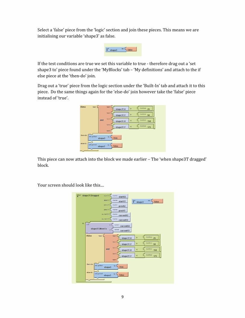
Select a ‘false’ piece from the ‘logic’ section and join these pieces. This means we are
initialising our variable ‘shape3’ as false.
If the test conditions are true we set this variable to true - therefore drag out a ‘set
shape3 to’ piece found under the ‘MyBlocks’ tab – ‘My definitions’ and attach to the if
else piece at the ‘then-do’ join.
Drag out a ‘true’ piece from the logic section under the ‘Built-In’ tab and attach it to this
piece. Do the same things again for the ‘else-do’ join however take the ‘false’ piece
instead of ‘true’.
This piece can now attach into the block we made earlier – The ‘when shape3T dragged’
block.
Your screen should look like this....

10
This is the logic needed for each piece therefore there is a lot of repetition. The steps
you have just completed need to be repeated for the remaining 4 pieces.
The logic of each piece is as follows:
Rectangle piece – shape5R
shape5R.X > 150 shape5R.Y <175 shape5R.X <275 shape5R.Y>50
Follow the diagram – and the steps you have taken and try to complete this piece. You
should end up with this...
Triangle piece – shape4T
shape4T.X > 25 shape4T.Y >50 shape4T.X <150 shape4T.Y<175
Follow the diagram – and the steps you have taken and try to complete this piece. You
should end up with this...

11
Square piece – shape2S
shape2S.X > 150 shape2S.Y >175 shape2S.X <275 shape2S.Y<300
Follow the diagram – and the steps you have taken and try to complete this piece. You
should end up with this...
12
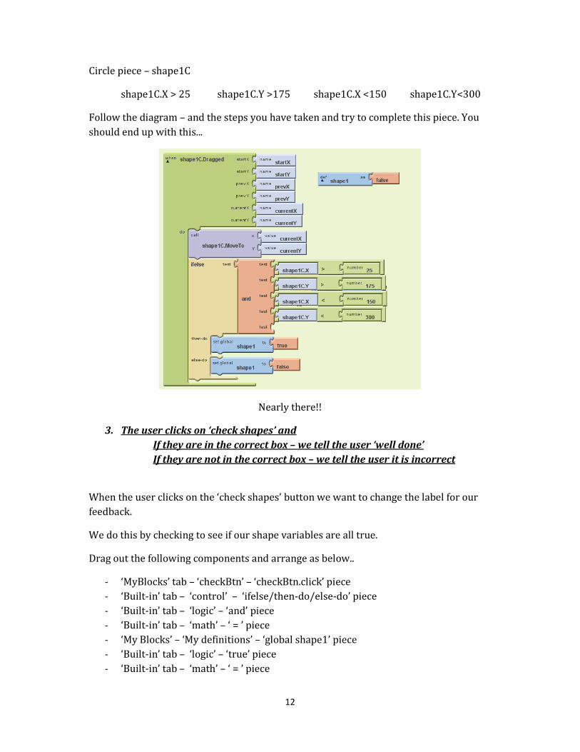
Circle piece – shape1C
shape1C.X > 25 shape1C.Y >175 shape1C.X <150 shape1C.Y<300
Follow the diagram – and the steps you have taken and try to complete this piece. You
should end up with this...
Nearly there!!
3. The user clicks on ‘check shapes’ and
If they are in the correct box – we tell the user ‘well done’
If they are not in the correct box – we tell the user it is incorrect
When the user clicks on the ‘check shapes’ button we want to change the label for our
feedback.
We do this by checking to see if our shape variables are all true.
Drag out the following components and arrange as below..
- ‘MyBlocks’ tab – ‘checkBtn’ – ‘checkBtn.click’ piece
- ‘Built-in’ tab – ‘control’ – ‘ifelse/then-do/else-do’ piece
- ‘Built-in’ tab – ‘logic’ – ‘and’ piece
- ‘Built-in’ tab – ‘math’ – ‘ = ’ piece
- ‘My Blocks’ – ‘My definitions’ – ‘global shape1’ piece
- ‘Built-in’ tab – ‘logic’ – ‘true’ piece
- ‘Built-in’ tab – ‘math’ – ‘ = ’ piece

13
- ‘My Blocks’ – ‘My definitions’ – ‘global shape2’ piece
- ‘Built-in’ tab – ‘logic’ – ‘true’ piece
- ‘Built-in’ tab – ‘math’ – ‘ = ’ piece
- ‘My Blocks’ – ‘My definitions’ – ‘global shape3’ piece
- ‘Built-in’ tab – ‘logic’ – ‘true’ piece
- ‘Built-in’ tab – ‘math’ – ‘ = ’ piece
- ‘My Blocks’ – ‘My definitions’ – ‘global shape4’ piece
- ‘Built-in’ tab – ‘logic’ – ‘true’ piece
- ‘Built-in’ tab – ‘math’ – ‘ = ’ piece
- ‘My Blocks’ – ‘My definitions’ – ‘global shape5’ piece
- ‘Built-in’ tab – ‘logic’ – ‘true’ piece
- ‘My Blocks’ – ‘feedbackLbl’ – ‘feedbackLbl.text’ piece
- ‘Built-in’ tab – ‘text’ – ‘text’ piece – change text to feedback message
- ‘My Blocks’ – ‘feedbackLbl’ – ‘feedbackLbl.textColor’ piece
- ‘Built-in’ tab – ‘colour’ – ‘green’ piece
- ‘My Blocks’ – ‘feedbackLbl’ – ‘feedbackLbl.text’ piece
- Built-in’ tab – ‘text’ – ‘text’ piece – change text to feedback message
- ‘My Blocks’ – ‘feedbackLbl’ – ‘feedbackLbl.textColor’ piece
- ‘Built-in’ tab – ‘colour’ – ‘red’ piece
That’s It – Try it out!!!

14
Step 4: Try it out – Connect to the device and test the program
Create a new emulator by clicking on the ‘New emulator’ button at the top of our blocks
editor.
You must wait for the emulator to load fully before you test your app.
Once the emulator is ready - connect and send your app. Select the device from the
device list. This process may take a few minutes. Please be Patient.
Your initial screen will have the 5 draggable
objects along the top. Drag one to its proper
location.
*Unfortunately, App Inventor is still an
experimental version and there appears to be
a small bug when using multiple image
sprites..
If any two objects cross paths they will
disappear… This can be overcome by changing
the enable property of the other image sprites.
Otherwise – try not to drag any object over a
previous one.
You have just created a functional Shape Sort
App, Well Done ☺
End Note: For the ShapeSort App we changed
the text/colour property of a label, we used
the drawing canvas component with image
sprites to create draggable objects.
We used Logic to test the location of our
dragged pieces and based on this logic gave
two different feedback output.