app inventor + iot: 60 read knob status with micro:bit i/o...
TRANSCRIPT
App Inventor + IoT:
read knob status with Micro:bit I/O
pins (with Basic Connection
tutorial completed)
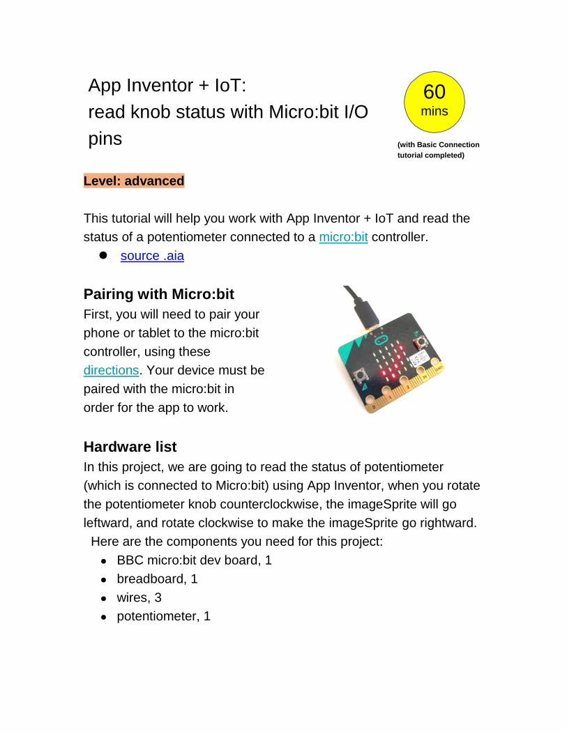
Level: advanced
This tutorial will help you work with App Inventor + IoT and read the
status of a potentiometer connected to a micro:bit controller.
source .aia
Pairing with Micro:bit
First, you will need to pair your
phone or tablet to the micro:bit
controller, using these
directions. Your device must be
paired with the micro:bit in
order for the app to work.
Hardware list
In this project, we are going to read the status of potentiometer
(which is connected to Micro:bit) using App Inventor, when you rotate
the potentiometer knob counterclockwise, the imageSprite will go
leftward, and rotate clockwise to make the imageSprite go rightward.
Here are the components you need for this project:
● BBC micro:bit dev board, 1
● breadboard, 1
● wires, 3
● potentiometer, 1
60 mins

Demo video: https://youtu.be/TQcRy1JkFBc
Please connect Micro:bit and RGB LED according to this table:
Micro:bit Potentiometer
GND right pin (grey wire)
P0 middle pin (green wire)
3V left pin (red wire)
Note: potentiometer is a non-polarized component, which means the
difference to connect potentiometer left pin to MCU board’s 5V pin
(another pin to GND pin) is that when you rotate potentiometer knob
clockwise, the pin value will change in opposite way than to connect
its right pin to MCU board’s 5V pin.

Finish as below, let’s take a look:
Or you can use extension board, like DFRobot’s BOSON
extension board :
Right pin signal left pin
GND 3V P0

App Inventor
This app will move an imageSprite back and forth according to how
you rotate the potentiometer on micro:bit. Technically speaking, App
Inventor is asking micro:bit to report its analog pin status and this is
where we connect the potentiometer to. First, log into MIT App
Inventor site and create a new project.
Designer
You should complete the App Inventor + IoT Basic Connection
tutorial to make a basic connection to the micro:bit device. If you
prefer, you can download the completed .aia file here.
The remaining steps all build off of the the starter code for Basic
Connection tutorial and its .aia source code.
First, we need to add the necessary extension.
● In the Palette window, click on Extension at the
bottom and then on "Import extension" and click on
"URL".
○ Paste micro:bit extension URL:
http://iot.appinventor.mit.edu/assets/com.bbc.mi
cro:bit.profile.aix
● Add a Microbit_IOpin extension to your app by
dragging it onto the Viewer, set its
BluetoothDevice to "BluetoothLE1"(Don’t
forget!).

Let’s add more components to our app to read the magnetometer
status.
● From the Drawing and animation palette, add a
Canvas component. Set its width to "Fill
parent", height to 150 pixels.
● From the Drawing and animation palette, add an
ImageSprite component, set its Picture to some
cute image (no bigger than the canvas).
● Add a label, set its FontSize to 60 and Text to
"pin data". We will update the micro:bit
potentiometer status here.
● From Sensor palette, add a Clock component,
set its TimerInterval to 100, which means its
timer will trigger 10 times per second.

After some adjusting, your designer should look similar to
this. It doesn’t have to be exactly the same. Feel free to
modify the component properties, such as background
color, position and text size.
Blocks
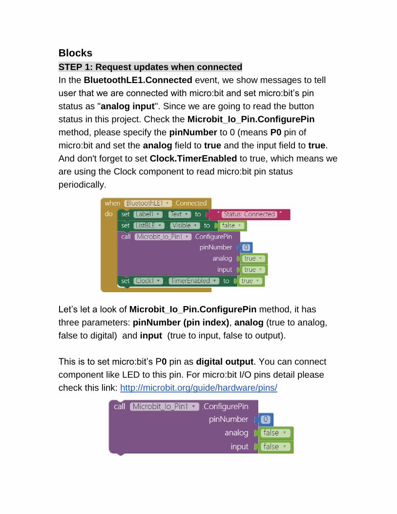
STEP 1: Request updates when connected
In the BluetoothLE1.Connected event, we show messages to tell
user that we are connected with micro:bit and set micro:bit’s pin
status as "analog input". Since we are going to read the button
status in this project. Check the Microbit_Io_Pin.ConfigurePin
method, please specify the pinNumber to 0 (means P0 pin of
micro:bit and set the analog field to true and the input field to true.
And don't forget to set Clock.TimerEnabled to true, which means we
are using the Clock component to read micro:bit pin status
periodically.
Let’s let a look of Microbit_Io_Pin.ConfigurePin method, it has
three parameters: pinNumber (pin index), analog (true to analog,
false to digital) and input (true to input, false to output).
This is to set micro:bit’s P0 pin as digital output. You can connect
component like LED to this pin. For micro:bit I/O pins detail please
check this link: http://microbit.org/guide/hardware/pins/

And this is to set micro:bit’s P2 pin as analog input. You can connect
component like potentiometer to this pin.
STEP2: read sensor status periodically
In Clock.Timer event, we call Microbit_Io_Pin.ReadInputPinData
method to read a specified micro:bit pin data, which is P0 in our case.
Since we’ve set Clock’s TimerInterval property to 100, this means
we are reading micro:bit pin data every 100 milliseconds (10 times
per second).
Note: you must configure the pin as analog input (in STEP1) to

read its data correctly.
STEP3: read sensor status periodically
Microbit_Io_Pin.PinDataReceived event will be called after the pin
data is read successfully, and it will return a list (pin index, pin data)
as a result. You can use a select list item method to get pin data
and show it on the label.
To make our app more interactive, we will move the ImageSprite
back and forth horizontally according to the pin data
(ImageSprite.MoveTo method).
Note: the data range of micro:bit analog input pin is from 0 to 255.
STEP4: Disconnect from micro:bit
You can disconnect from micro:bit by clicking the ButtonDisconnect
button. This will reset the app to its initial state to wait for next
connect request.
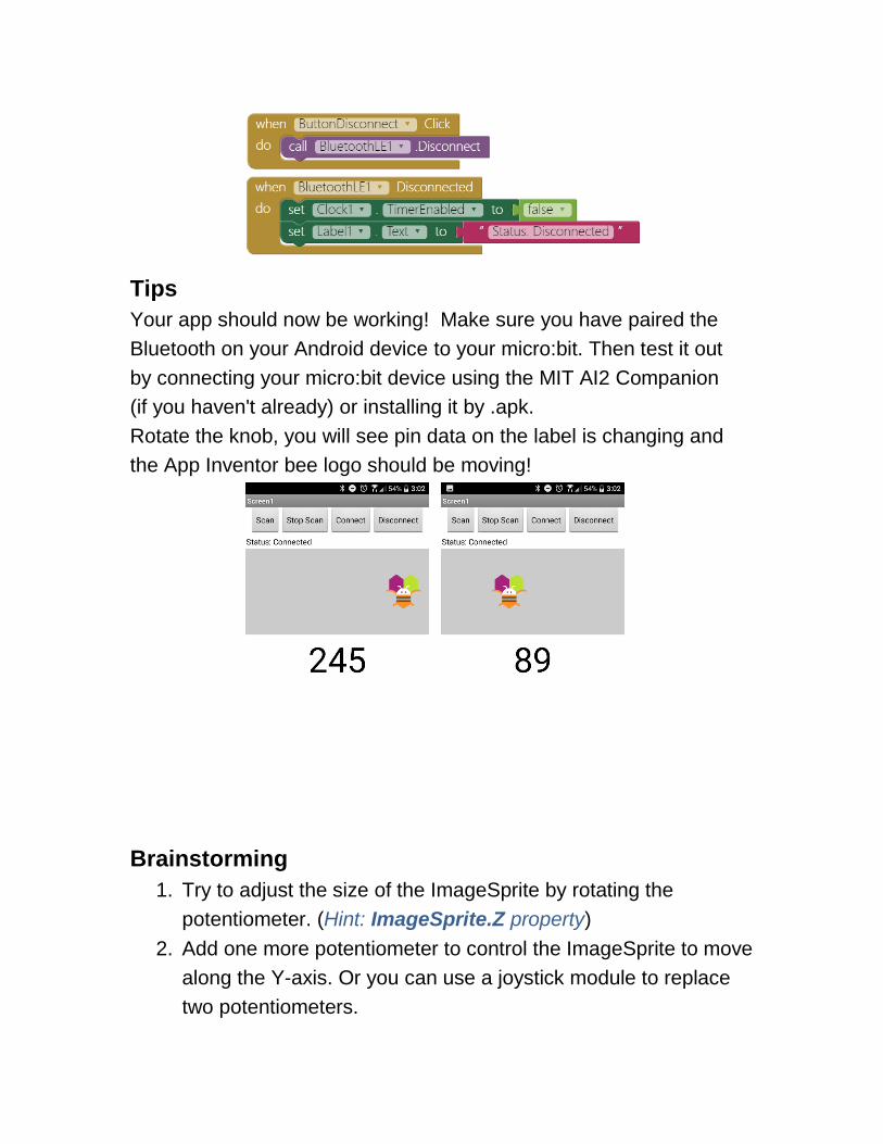
Tips
Your app should now be working! Make sure you have paired the
Bluetooth on your Android device to your micro:bit. Then test it out
by connecting your micro:bit device using the MIT AI2 Companion
(if you haven't already) or installing it by .apk.
Rotate the knob, you will see pin data on the label is changing and
the App Inventor bee logo should be moving!
Brainstorming
1. Try to adjust the size of the ImageSprite by rotating the
potentiometer. (Hint: ImageSprite.Z property)
2. Add one more potentiometer to control the ImageSprite to move
along the Y-axis. Or you can use a joystick module to replace
two potentiometers.

(joystick module on Arduino.cc)
Hint: you can connect two potentiometers to micro:bit, one
potentiometer signal pin to micro:bit P0 and the other’s to micro:bit
P1, finish like this:
Connect joystick’s vertical pin to micro:bit P0, horizontal pin to
micro:bit P1, finish like this: