apollo software manual - sound productions · apollo software overview ... 13 registration ... the...
TRANSCRIPT
Apollo Software Manual
Software Version 7.9
Customer Service & Technical Support:
USA Toll-Free: +1-877-698-2834
International: +1-831-440-1176
www.uaudio.com
H I G H - R E S O L U T I O N I N T E R F A C Ewith Realtime UAD Processing
Manual Version 140616

Apollo Software Manual Table Of Contents2
Table Of Contents
Chapter 1: Introduction ......................................................................... 4Welcome To The Apollo Family ............................................................................ 4
Software Features .............................................................................................. 5
System Requirements ........................................................................................ 6
Documentation Overview .................................................................................... 7
Apollo Software Overview .................................................................................... 9
Technical Support ............................................................................................ 11
Chapter 2: Installation & Setup ............................................................ 12Installation & Setup Overview ........................................................................... 12
Software Installation ........................................................................................ 13
Registration & Authorization ............................................................................. 14
Optimizing FireWire Performance ...................................................................... 16
Chapter 3: Console Application ............................................................ 18Console Overview ............................................................................................. 18
The Console Mixer Window ............................................................................... 22
Channel Input Strips ........................................................................................ 24
Inserts ............................................................................................................ 29
Auxiliary Section .............................................................................................. 41
Monitor Section ............................................................................................... 45
Cue Returns (Apollo 16 only) ............................................................................ 49
Console Settings Window .................................................................................. 58
Window Title Bar .............................................................................................. 64
Application Menus ........................................................................................... 66
Chapter 4: Console Recall Plug-In ........................................................ 70Console Recall Overview ................................................................................... 70
Console Recall Controls .................................................................................... 71
SYNC ............................................................................................................. 72
Tip: Click any section or page number to jump directly to that page.
Apollo Software Manual Table Of Contents3
Chapter 5: Unison .............................................................................. 74What is Unison? .............................................................................................. 74
Unison PREAMP Inserts ................................................................................... 76
Controlling Unison Plug-Ins with Apollo ............................................................. 77
Unison Load/Save Behaviors ............................................................................. 83
Unison Operation Notes .................................................................................... 84
Chapter 6: Working With Apollo ............................................................ 86Apollo Setups Overview .................................................................................... 86
About UAD Powered Plug-Ins Processing............................................................ 87
Using Apollo as an Audio Interface .................................................................... 89
Using Apollo with Console (without a DAW) ........................................................ 91
Using Apollo Without A Computer ...................................................................... 92
Using Apollo with a DAW (without Console) ........................................................ 93
Using Apollo Concurrently with a DAW and Console ............................................. 95
Virtual I/O ....................................................................................................... 97
PT Mode ......................................................................................................... 99
Chapter 7: Multi-Unit Cascading ........................................................ 100Multi-Unit Overview ....................................................................................... 100
Multi-Unit Wiring Diagrams............................................................................. 101
Multi-Unit Operation ...................................................................................... 105
Chapter 8: Latency & Apollo .............................................................. 109Delay Compensation with Apollo ...................................................................... 109
Input Delay Compensation in Console .............................................................. 109
Upsampled UAD Plug-Ins Table ...................................................................... 112
Latency Basics .............................................................................................. 113
Chapter 9: Device Drivers .................................................................. 116Apollo Drivers Overview .................................................................................. 116
Driver I/O Tables ............................................................................................ 117

Apollo Software Manual Table Of Contents4
Chapter 10: Glossary ......................................................................... 132
Chapter 11: Index ............................................................................. 139
Chapter 12: Notices .......................................................................... 142Disclaimer .................................................................................................... 142
Trademarks ................................................................................................... 142
Copyright ...................................................................................................... 142
Apollo Software Manual Chapter 1: Introduction 5
Chapter 1: Introduction
Welcome To The Apollo Family
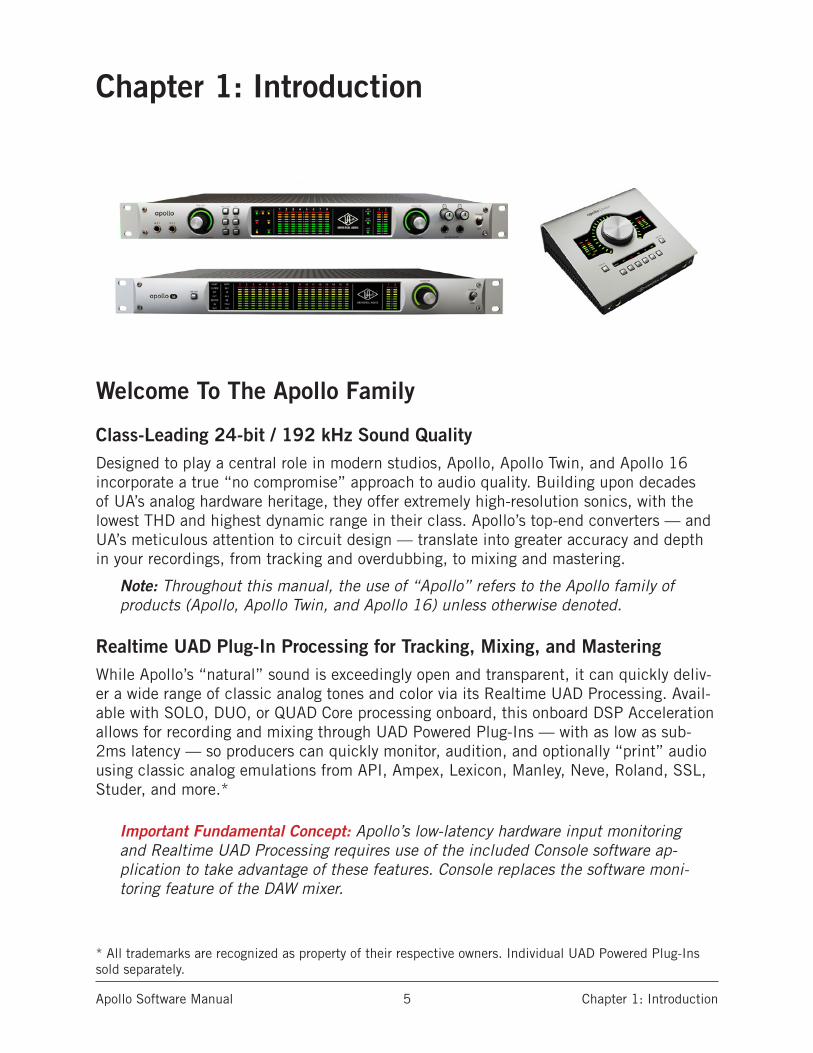
Class-Leading 24-bit / 192 kHz Sound Quality Designed to play a central role in modern studios, Apollo, Apollo Twin, and Apollo 16 incorporate a true “no compromise” approach to audio quality. Building upon decades of UA’s analog hardware heritage, they offer extremely high-resolution sonics, with the lowest THD and highest dynamic range in their class. Apollo’s top-end converters — and UA’s meticulous attention to circuit design — translate into greater accuracy and depth in your recordings, from tracking and overdubbing, to mixing and mastering.
Note: Throughout this manual, the use of “Apollo” refers to the Apollo family of products (Apollo, Apollo Twin, and Apollo 16) unless otherwise denoted.
Realtime UAD Plug-In Processing for Tracking, Mixing, and MasteringWhile Apollo’s “natural” sound is exceedingly open and transparent, it can quickly deliv-er a wide range of classic analog tones and color via its Realtime UAD Processing. Avail-able with SOLO, DUO, or QUAD Core processing onboard, this onboard DSP Acceleration allows for recording and mixing through UAD Powered Plug-Ins — with as low as sub-2ms latency — so producers can quickly monitor, audition, and optionally “print” audio using classic analog emulations from API, Ampex, Lexicon, Manley, Neve, Roland, SSL, Studer, and more.*
Important Fundamental Concept: Apollo’s low-latency hardware input monitoring and Realtime UAD Processing requires use of the included Console software ap-plication to take advantage of these features. Console replaces the software moni-toring feature of the DAW mixer.
* All trademarks are recognized as property of their respective owners. Individual UAD Powered Plug-Ins sold separately.

Apollo Software Manual Chapter 1: Introduction 6
Software FeaturesNote: For a list of hardware features, see the Apollo Hardware Manuals.
Console Application
General:
• Remote control of Apollo hardware features and functionality • Analog-style mixer for realtime monitoring and tracking with UAD plug-ins• Enables Realtime UAD Powered Plug-Ins processing on all inputs• Console settings can be saved/loaded for instant recall of any configuration
Realtime UAD Processing:
• Up to four UAD plug-ins can be serially chained on each input and aux return• UAD insert processing can be monitored “wet” while recording wet or dry• Sub-2ms round-trip latency with four serial UAD plug-ins at 96 kHz sample rate
Channel Inputs:
• Input channels for all interface hardware inputs (except MADI with Apollo 16)
• Level, pan, solo, and mute controls on all inputs• Four plug-in insert slots per input for Realtime UAD processing• Two stereo auxiliary sends with level and pan controls on all inputs• Virtual inputs accept any outputs from DAW via device drivers• Stereo headphone sends with level and pan controls on all inputs*• Four stereo cue sends with level and pan controls on all inputs*• Adjacent input pairs can be linked for convenient stereo control• Sample rate conversion is available on S/PDIF and AES/EBU inputs*• Any input can be routed to any output (except Apollo Twin)
Monitoring:
• Stereo monitor mix bus with level, mute, solo clear, and source select controls• Independent headphone buses; switchable to monitor mix and/or mirror to any output*• 4 stereo cue mix buses; switchable to monitor mix and/or mirror to any output (Apollo 16)
• Independent monophonic sum controls for all mix buses• S/PDIF and AES/EBU outputs can optionally mirror the post-fader monitor mix*
Auxiliary and Cue Buses:
• Two stereo auxiliary returns with independent level, mute, and mono sum controls• Four plug-in inserts per auxiliary return for Realtime UAD processing• Auxiliary buses can be routed to main monitor mix or headphone & cue outputs*• Auxiliary & cue buses can be routed to any output*• Independent pre/post switching on each auxiliary bus
*Specific software features depend on hardware functionality not available with all Apollo devices. Details within.

Apollo Software Manual Chapter 1: Introduction 7
Metering:
• Signal level meters with peak hold and clip indicators on all inputs• Dual pin-style peak meters with signal peak LEDs display monitor bus levels• Input meters are globally switchable to display pre or post fader signal levels• Independently selectable peak/clip hold times and global clear clips button
Console Recall plug-in• Convenient access to Console’s monitor controls via DAW plug-in• Saves complete Apollo configurations inside DAW projects for easy recall of settings• VST, RTAS, AAX 64, and Audio Units plug-in formats
UAD Powered Plug-Ins• Award-winning audio plug-ins for monitoring, tracking, mixing, and mastering• UAD plug-ins can be used simultaneously within Console and/or DAW• All UAD plug-ins include fully-functional 14-day demo period• Complete UAD plug-ins library is available online at www.uaudio.com
UAD Meter & Control Panel application• UAD Control Panel configures global UAD-2 and UAD Powered Plug-Ins settings• UAD Meter monitors UAD-2 DSP resources and FireWire bandwidth
Device Drivers• 64-bit device drivers and plug-ins for Mac OS X and Windows 7*• Supports multi-unit cascading and multi-client output (except Apollo Twin)
• All hardware inputs and outputs can be individually addressed by DAW• All of Console’s mix buses can be routed to DAW inputs for recording
System RequirementsWindows
• Windows 7 64-bit Edition• Qualified PCIe-to-FireWire 800 adapter card (list is published here)
Mac*
• Mac OS X 10.8 Mountain Lion or 10.9 Mavericks• Available FireWire 800 port or Thunderbolt port
All Platforms
• 2 gigabytes available disk space• 1024 x 800 minimum display resolution• Internet connection to download software and authorize UAD plug-ins• For additional compatibility information, visit www.uaudio.com/support• For installation software, visit www.uaudio.com/download
*Apollo Twin requires a Mac computer with an available Thunderbolt port.
Apollo Software Manual Chapter 1: Introduction 8
Documentation OverviewDocumentation for all Apollo components is extensive, so instructions are separated by areas of functionality, as detailed below. All documentation is copied to the computer during software installation (documentation can also be downloaded from our website).
All manuals are in PDF format. PDF files require a free PDF reader application such as Adobe Reader (Windows) or Preview (included with Mac OS X). After software installa-tion, all Apollo documentation can be found on the startup drive at the following location locations:
Mac OS X
• Macintosh HD/Applications/Universal Audio
Windows 7
• Start>All Programs>UAD Powered Plug-Ins>DocumentationTip: Documentation can also be found by clicking the Documentation button in the Help panel within the UAD Meter & Control Panel application.
Apollo Hardware ManualsThe Apollo Hardware Manual, Apollo Twin Hardware Manual, and Apollo 16 Hardware Manual (all available separately) contain complete information about the audio interface hardware. Included are detailed descriptions for all Apollo hardware features, control functions, and connections. Refer to the Apollo Hardware Manuals to learn all about in-terfacing the hardware with other devices, operating the panel controls, clocking, specifi-cations, and related information.
Apollo Software ManualThe Apollo Software Manual is the companion guide to the Apollo Twin Hardware manu-al. It contains detailed information about how to configure and control Apollo’s software features using the Console application and Console Recall plug-in. Refer to the Apollo Software Manual to learn how to operate these software tools and integrate Apollo’s audio interface functionality into the DAW environment.
UAD System ManualThe UAD System Manual is the complete operation manual for Apollo’s UAD-2 function-ality and applies to the entire UAD product line. It contains detailed information about installing and configuring UAD devices, the UAD Meter & Control Panel application, how to use UAD plug-ins within a DAW, obtaining optional plug-in licenses at the UA online store, and more. It includes everything about UAD except Apollo Twin-specific informa-tion and individual UAD Powered Plug-In descriptions.
UAD Plug-Ins ManualThe features and functionality of all the individual UAD Powered Plug-Ins is detailed in the UAD Plug-Ins Manual. Refer to that document to learn about the operation, controls, and user interface of each plug-in that is developed by Universal Audio.

Apollo Software Manual Chapter 1: Introduction 9
Direct Developer Plug-InsUAD Powered Plug-Ins includes plug-ins from our Direct Developer partners. Documen-tation for these 3rd-party plug-ins are separate files that are written and provided by the plug-in developers themselves. The filenames for these plug-ins are the same as the plug-in title names.
Thunderbolt Option Card (Apollo & Apollo 16 only)All user documentation for the Thunderbolt Option Card is located on the Thunderbolt Support Page on our website (there is no separate manual). Please review the informa-tion on the page carefully before installing or using the device:
• www.uaudio.com/support/thunderbolt-support
Host DAW DocumentationEach host DAW application has its own particular methods for configuring audio inter-faces and using plug-ins. Refer to the host DAW’s documentation for specific instructions about using audio interface and plug-in features within the DAW.
Helpful videos about setting up Apollo with various DAWs are available on our website:
• www.uaudio.com/videos
HyperlinksLinks to other manual sections and web pages are highlighted in blue text. Click a hyper-link to jump directly to the linked item.
Tip: Use the “back” button in the PDF reader application to return to the previous page after clicking a hyperlink.
Information & Software UpdatesThe latest technical information and software for Apollo is posted on the Universal Audio website. Our support pages may contain updated, late-breaking information that is not available in other publications. Please visit the support page for your device:
Apollo & Apollo 16
• www.uaudio.com/support/apollo
Apollo Twin
• www.uaudio.com/support/twin
GlossaryThis manual uses technical terms and acronyms that may be unfamiliar. Refer to “Chapter 10: Glossary” beginning on page 134 for the definitions of many of these terms.
Apollo Software Manual Chapter 1: Introduction 10
Apollo Software OverviewApollo has several software components that comprise the complete Apollo system. A brief description of each component is provided below, along with a link to complete details about the component.
Console Application The Console application is Apollo’s primary software interface. Its main function is to control the hardware unit and its digital mixing and monitoring capabilities. The Console mixer is where Realtime UAD processing using UAD Powered Plug-Ins is configured.
Important Fundamental Concept: The primary function of Console is to control Apollo’s low-latency hardware input monitoring and Realtime UAD Processing, and Console must be used to take advantage of these features. Console replaces the software monitoring feature of the DAW mixer.
For complete details, see “Chapter 3: Console Application” beginning on page 19.
Console Recall Plug-InConsole Recall is a DAW plug-in supplied in VST, RTAS, AAX 64, and Audio Units for-mats. Console Recall offers additional convenience when using Apollo and/or the Console application in conjunction with a DAW. Its primary function is to store complete Console configurations within the DAW project file.
For complete details, see “Chapter 4: Console Recall Plug-In” beginning on page 71.
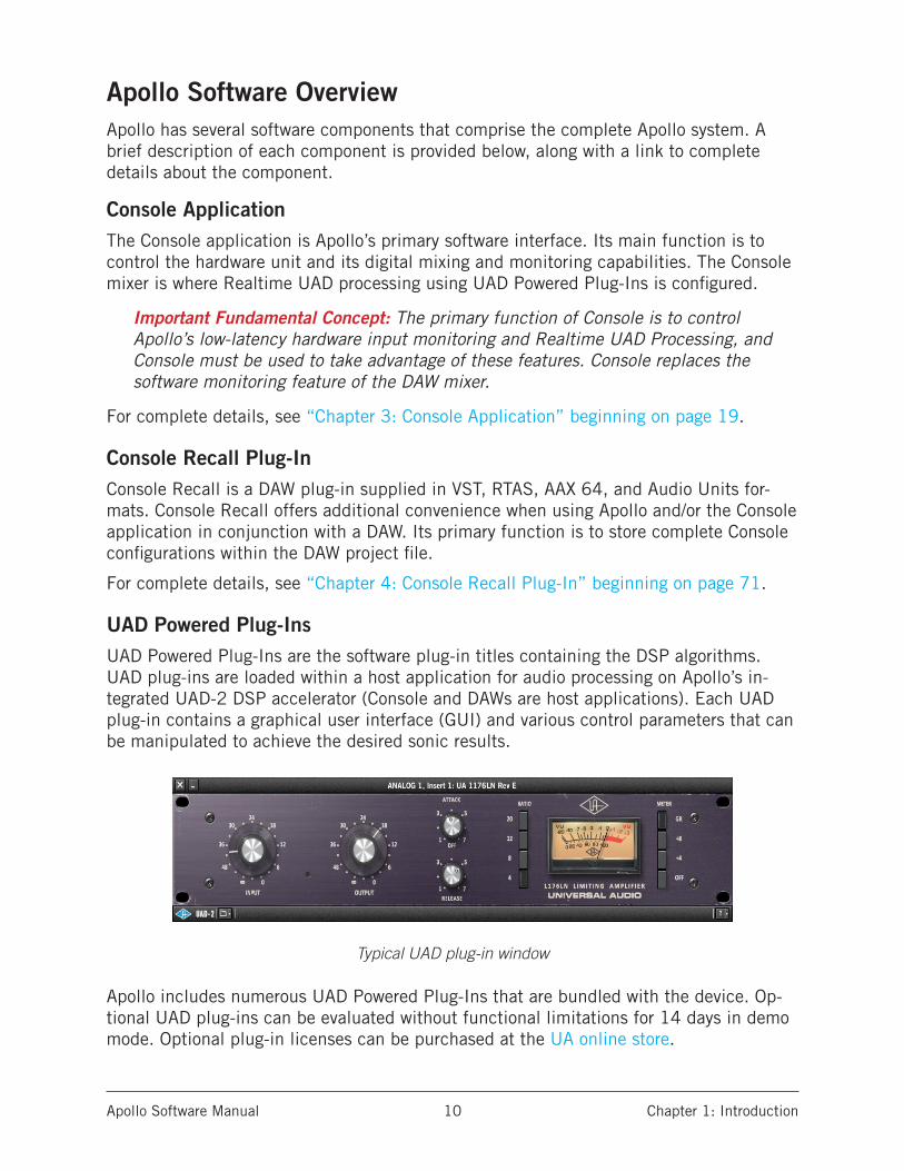
UAD Powered Plug-InsUAD Powered Plug-Ins are the software plug-in titles containing the DSP algorithms. UAD plug-ins are loaded within a host application for audio processing on Apollo’s in-tegrated UAD-2 DSP accelerator (Console and DAWs are host applications). Each UAD plug-in contains a graphical user interface (GUI) and various control parameters that can be manipulated to achieve the desired sonic results.
Typical UAD plug-in window
Apollo includes numerous UAD Powered Plug-Ins that are bundled with the device. Op-tional UAD plug-ins can be evaluated without functional limitations for 14 days in demo mode. Optional plug-in licenses can be purchased at the UA online store.
Apollo Software Manual Chapter 1: Introduction 11
For additional details about how UAD Powered Plug-Ins are used with Console and DAWs, see “About UAD Powered Plug-Ins Processing” on page 88. For general UAD Powered Plug-Ins usage instructions, see the UAD System Manual. For complete details of individual UAD Powered Plug-Ins, see the UAD Plug-Ins Manual.
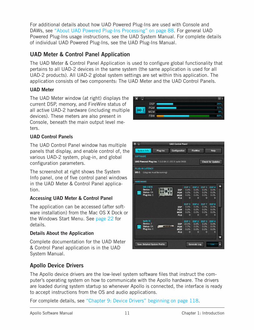
UAD Meter & Control Panel ApplicationThe UAD Meter & Control Panel Application is used to configure global functionality that pertains to all UAD-2 devices in the same system (the same application is used for all UAD-2 products). All UAD-2 global system settings are set within this application. The application consists of two components: The UAD Meter and the UAD Control Panels.
UAD Meter
The UAD Meter window (at right) displays the current DSP, memory, and FireWire status of all active UAD-2 hardware (including multiple devices). These meters are also present in Console, beneath the main output level me-ters.
UAD Control Panels
The UAD Control Panel window has multiple panels that display, and enable control of, the various UAD-2 system, plug-in, and global configuration parameters.
The screenshot at right shows the System Info panel, one of five control panel windows in the UAD Meter & Control Panel applica-tion.
Accessing UAD Meter & Control Panel
The application can be accessed (after soft-ware installation) from the Mac OS X Dock or the Windows Start Menu. See page 22 for details.
Details About the Application
Complete documentation for the UAD Meter & Control Panel application is in the UAD System Manual.
Apollo Device DriversThe Apollo device drivers are the low-level system software files that instruct the com-puter’s operating system on how to communicate with the Apollo hardware. The drivers are loaded during system startup so whenever Apollo is connected, the interface is ready to accept instructions from the OS and audio applications.
For complete details, see “Chapter 9: Device Drivers” beginning on page 118.
Apollo Software Manual Chapter 1: Introduction 12
Technical SupportUniversal Audio provides free customer support to all registered Apollo users. Our sup-port specialists are available to assist you via email and telephone during our normal business hours, which are from 9am to 5pm, Monday through Friday, Pacific Standard Time.
Telephone
USA toll-free: +1-877-698-2834 International: +1-831-440-1176
Online Support
To request online support via email, please visit the main support page at www.uaudio.com/support, then click the blue “Submit Support Ticket” button on the right side of the page to create a help ticket.
Click the link below for a direct link to the help ticket form:
• www.uaudio.com/my/support/index.php?pg=request
Users Forum
The unofficial UAD Powered Plug-Ins users forum, for the exchange of tips and informa-tion, is on the web at:
• www.uadforum.com
Apollo Software Manual Chapter 2: Installation & Setup 13
Chapter 2: Installation & Setup
Installation & Setup OverviewSimplified procedures for software installation, registration, and authorization are in this chapter. For complete and detailed procedures, refer to the UAD System Manual. For hardware installation notes and diagrams, refer to the Apollo Hardware Manuals. If you need technical assistance, contact technical support (page 15).
The UAD Installer places all the software necessary to configure and use Apollo and UAD Powered Plug-Ins onto the computer’s startup disk. It also installs the Apollo hardware device drivers so the audio interface can communicate with the host computer. Therefore the UAD Installer must be run even if you intend to use Apollo without the use of Con-sole or UAD Powered Plug-Ins functionality.
Installation, registration, and authorization consists of these main steps (detailed later):1. (Windows only): Install a qualified PCIe-to-FireWire adapter card.2. UAD software installation: Run the installer downloaded from our website.3. Connect Apollo to the host computer (and other gear): See example setups in the
Apollo Hardware Manuals.4. Device registration and UAD plug-in authorization: Register with a my.uaudio ac-
count to claim bundled plug-ins.5. UAD plug-in authorization: Download and apply the UAD authorization file.6. Optimizing FireWire performance (except with Thunderbolt): Adjust the UAD
Bandwidth Allocation setting based upon your particular operating environment.
System RequirementsThe System Requirements must be met before installing the Apollo hardware or software.
Important: On Windows computers, the required PCIe-to-FireWire adapter card must be installed and configured correctly before installing the UAD software or connecting Apollo.
Software UpdatesThe latest UAD Powered Plug-Ins software version is always recommended. If the soft-ware is already installed, the UAD Meter & Control Panel application has a convenient button that check for the most recent version. Please check our website for the latest software at: www.uaudio.com/downloads
PreparationClose all open files and applications before starting the software installation procedure (the installer requires a restart after installation).
If you are updating to a newer version of Apollo software or installing additional UAD devices, it is not necessary to remove the previous UAD software or hardware from the system.
Apollo Software Manual Chapter 2: Installation & Setup 14
Software InstallationImportant: If you are installing Apollo for the first time, install the UAD Powered Plug-Ins software before connecting the Apollo hardware. For optimum results, download the most recent version of the UAD software from our website.
Note: Software for Apollo and other UAD-2 devices (if any) must be installed at the same time – software for UAD-2 devices cannot be installed separately.
To install the Apollo software:
1. Launch the UAD Powered Plug-Ins installer downloaded from our website at: www.uaudio.com/download
2. The installer will guide you through the process3. Shut down the computer before connecting the hardware
(Mac systems can be hot-plugged after restarting) 4. Connect Apollo to the computer with the included FireWire 800 cable5. Connect Apollo to AC power with the included power cable, then power it on with
the front panel switch6. Start the computer. On Windows systems, the Apollo software is installed after
restarting7. If prompted to update the Apollo firmware, click "OK" then wait for confirmation
that the process is complete (Apollo must be powered off then on after a firmware update to complete the process)
8. Proceed to Registration & Authorization below to complete the setup process.
Firmware Updates
Important: For optimum results, always update the firmware if prompted by the software. A confirmation dialog will appear after the firmware update is complete; power Apollo off then on again to complete the process before attempting to use the software.

Apollo Software Manual Chapter 2: Installation & Setup 15
Registration & AuthorizationApollo must be registered and authorized at my.uaudio.com to unlock its UAD-2 func-tionality. Apollo can be used as a normal audio interface (without UAD Powered Plug-Ins) without registration and authorization. Unlicensed UAD-2 plug-ins can be used in demo mode for 14 days without authorization.
Registration only needs to be completed once, however authorization must be completed each time the UAD software is updated. Apollo, like all UAD-2 devices, stores its autho-rization and UAD licenses in the device itself, so the unit can be connected to a different computer without repeating the authorization process.
Important: Registration and authorization can only be accomplished after success-ful software installation
To register and authorize Apollo:
Note: Registration is part of the initial authorization process (it’s not a separate procedure). The following steps require an Internet connection to the host com-puter. To authorize a system that is not online, see the UAD System Manual.
1. Ensure that the Apollo software is installed and Apollo is powered up and con-nected to the computer via FireWire or Thunderbolt (the hardware and software systems must be communicating properly)
2. Open the UAD Meter & Control Panel application. It can be accessed via the following methods:
• (Mac) Click its icon in the OS X Dock• (Win) Select it from Start Menu>All Programs>UAD Powered Plug-Ins
3. Open the “Plug-Ins” panel within the UAD Meter & Control Panel application. Access the panel by clicking the menu button in the UAD Meter window and selecting “Plug-Ins...” from the drop menu.
Apollo Software Manual Chapter 2: Installation & Setup 16
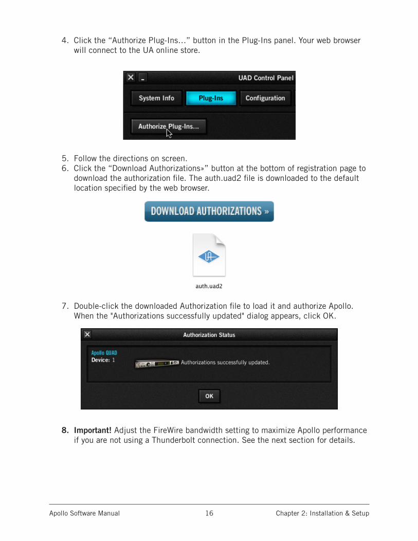
4. Click the “Authorize Plug-Ins…” button in the Plug-Ins panel. Your web browser will connect to the UA online store.
5. Follow the directions on screen.6. Click the “Download Authorizations»” button at the bottom of registration page to
download the authorization file. The auth.uad2 file is downloaded to the default location specified by the web browser.
7. Double-click the downloaded Authorization file to load it and authorize Apollo. When the "Authorizations successfully updated" dialog appears, click OK.
8. Important! Adjust the FireWire bandwidth setting to maximize Apollo performance if you are not using a Thunderbolt connection. See the next section for details.

Apollo Software Manual Chapter 2: Installation & Setup 17
Optimizing FireWire PerformanceImportant: This section only applies when connected to the computer via FireWire. It is not applicable when connected via Thunderbolt.
About FireWire BandwidthFireWire bandwidth is shared between Apollo I/O streams, UAD plug-ins used within the DAW, and external FireWire hard drives. Available bandwidth also depends on the session sample rate; the higher the sample rate, the more bandwidth is consumed.
FireWire bandwidth is displayed in the “FBW” meter in the UAD Meter & Control Panel application:
The FireWire Bandwidth meter in the UAD Meter & Control Panel application
UAD Bandwidth AllocationThe UAD Bandwidth Allocation setting reserves FireWire bandwidth for UAD plug-ins used within a DAW. It has no effect on UAD plug-ins used in Console, nor when connect-ed to the host computer via Thunderbolt. The default value (65%) a good starting point for most single-unit users; it should be adjusted according to your particular environ-ment. Use the values in the table below as starting points when tuning the UAD Band-width Allocation. The values apply for both Apollo and Apollo 16.
Note: If using sample rates of 44.1 kHz or 48 kHz, we recommend increasing the UAD Bandwidth Allocation setting from the default of 65% to allow more UAD plug-ins to run within the DAW when external FireWire hard drives are not used.
Recommended UAD Bandwidth Allocation Values (single unit)
Sample Rate (kHz): 44.1, 48 88.2, 96 176.4, 192
Without external FireWire hard driveMac: 80% 65% 55%
Win: 75% 55% 45%
With external FireWire hard driveMac: 55% 40% 25%
Win: 30% 25% 15%
I/O buffer setting for best playback results 512 1024 2048
Note: See "Multi-Unit FireWire Bandwidth" on page 108 for recommended val-ues when multi-unit cascading.
Used by I/O streams (orange)
Used by UAD plug-ins (blue) Available for UAD plug-ins (green)
Available for hard drive streams (black)
Apollo Software Manual Chapter 2: Installation & Setup 18
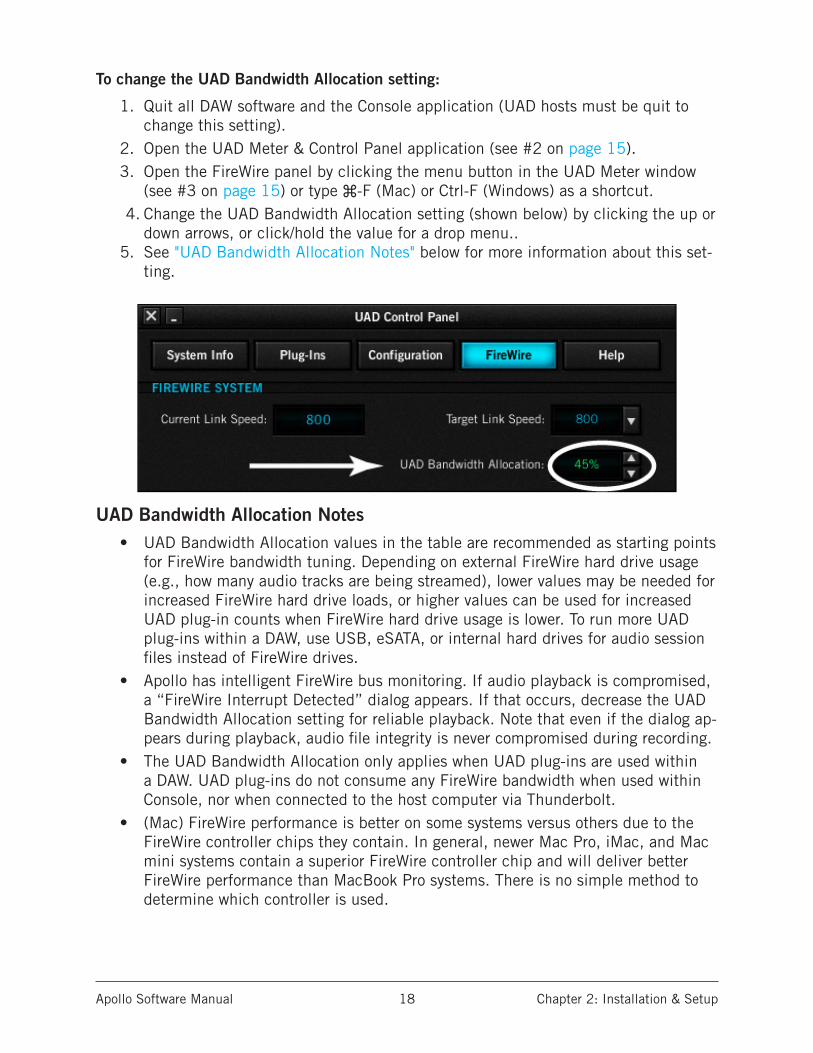
To change the UAD Bandwidth Allocation setting:
1. Quit all DAW software and the Console application (UAD hosts must be quit to change this setting).
2. Open the UAD Meter & Control Panel application (see #2 on page 15).3. Open the FireWire panel by clicking the menu button in the UAD Meter window
(see #3 on page 15) or type ⌘-F (Mac) or Ctrl-F (Windows) as a shortcut. 4. Change the UAD Bandwidth Allocation setting (shown below) by clicking the up or
down arrows, or click/hold the value for a drop menu..5. See "UAD Bandwidth Allocation Notes" below for more information about this set-
ting.
UAD Bandwidth Allocation Notes• UAD Bandwidth Allocation values in the table are recommended as starting points
for FireWire bandwidth tuning. Depending on external FireWire hard drive usage (e.g., how many audio tracks are being streamed), lower values may be needed for increased FireWire hard drive loads, or higher values can be used for increased UAD plug-in counts when FireWire hard drive usage is lower. To run more UAD plug-ins within a DAW, use USB, eSATA, or internal hard drives for audio session files instead of FireWire drives.
• Apollo has intelligent FireWire bus monitoring. If audio playback is compromised, a “FireWire Interrupt Detected” dialog appears. If that occurs, decrease the UAD Bandwidth Allocation setting for reliable playback. Note that even if the dialog ap-pears during playback, audio file integrity is never compromised during recording.
• The UAD Bandwidth Allocation only applies when UAD plug-ins are used within a DAW. UAD plug-ins do not consume any FireWire bandwidth when used within Console, nor when connected to the host computer via Thunderbolt.
• (Mac) FireWire performance is better on some systems versus others due to the FireWire controller chips they contain. In general, newer Mac Pro, iMac, and Mac mini systems contain a superior FireWire controller chip and will deliver better FireWire performance than MacBook Pro systems. There is no simple method to determine which controller is used.
Apollo Software Manual Chapter 3: Console Application 19
Chapter 3: Console Application
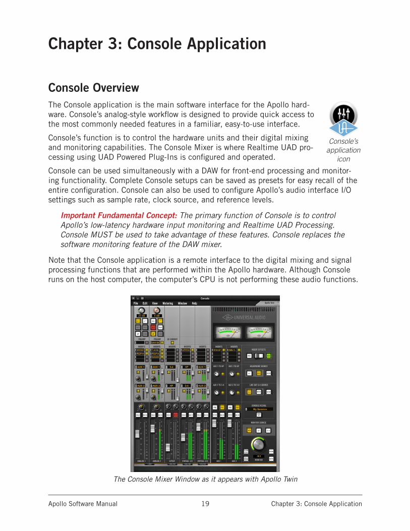
Console OverviewThe Console application is the main software interface for the Apollo hard-ware. Console’s analog-style workflow is designed to provide quick access to the most commonly needed features in a familiar, easy-to-use interface.
Console’s function is to control the hardware units and their digital mixing and monitoring capabilities. The Console Mixer is where Realtime UAD pro-cessing using UAD Powered Plug-Ins is configured and operated.
Console can be used simultaneously with a DAW for front-end processing and monitor-ing functionality. Complete Console setups can be saved as presets for easy recall of the entire configuration. Console can also be used to configure Apollo’s audio interface I/O settings such as sample rate, clock source, and reference levels.
Important Fundamental Concept: The primary function of Console is to control Apollo’s low-latency hardware input monitoring and Realtime UAD Processing. Console MUST be used to take advantage of these features. Console replaces the software monitoring feature of the DAW mixer.
Note that the Console application is a remote interface to the digital mixing and signal processing functions that are performed within the Apollo hardware. Although Console runs on the host computer, the computer’s CPU is not performing these audio functions.
The Console Mixer Window as it appears with Apollo Twin
Console’s application
icon
Apollo Software Manual Chapter 3: Console Application 20
Console FunctionsConsole enables the following functionality when used with Apollo:
• Hardware control. Apollo’s front panel hardware controls (except headphone vol-ume) can be controlled using Console, facilitating easy hardware control even if Apollo is installed in a location out of reach of the host computer operator.
• Buffer-free monitoring. Using Console eliminates DAW I/O buffering and its asso-ciated latency that makes monitoring and recording problematic for the performer. By removing the DAW and its “software monitoring” feature from the monitoring signal flow altogether, buffering and latency become non-issues.
• Realtime UAD processing. UAD Powered Plug-Ins can be inserted into all Console inputs and/or auxiliary returns (within available DSP resources), for the ultimate sonic experience while monitoring and/or tracking live performances. All pro-cessed (or unprocessed) mix buses, including the monitor, auxiliary, headphone, and cue buses, can be optionally routed into the DAW for recording.
• Unison. Apollo’s Unison technology gives you the tone of the world’s most sought-after tube and solid state mic preamps — including their all-important imped-ance, gain stage “sweet spots,” and component-level circuit behaviors.
• Flexible, independent monitor mixing and tracking. Console has two pre/post stereo auxiliary buses, with independent send levels per input, for grouped signal processing (conserving DSP resources) or routing to alternate hardware outputs. Two stereo headphone mix buses (Apollo) or four stereo cue mix buses (Apollo 16) with per-input sends ensure individual performers can hear “more me” if desired.
• Flexible signal routing. Using Console, any hardware input can be routed to any hardware output (Apollo/Apollo 16 only). Additionally, all headphone (Apollo/Apol-lo Twin) and cue (Apollo 16) mix buses can be mirrored to any hardware output.
• Session management. Complete Console configurations can be saved and loaded to/from disk as presets, for convenient and unlimited session management. Ses-sions can also be stored within the DAW project using the Console Recall plug-in.
Global SettingsParameters within the Console Settings Window panels are available for configuring vari-ous global behaviors:
• Hardware. Global interface settings such as sample rate, clock source, reference levels, and digital output mirroring are controlled in the Interface panel.
• Software. Global software settings for Console such as meter and plug-in window behaviors are configured in the Console panel.
Interactions Between Console and Apollo Console’s settings mirror the Apollo hardware; changes made to one will be made on the other, and vice versa. If changes are made to Console when Apollo is not connected, then Apollo is subsequently connected, the Console settings are sent to the hardware.
Important: If Console is launched after changes are made to Apollo using the front panel hardware controls, the current Console settings will overwrite the changes made using the hardware controls.

Apollo Software Manual Chapter 3: Console Application 21
When To Use ConsoleThe Console application can be used without a DAW, simultaneously in conjunction with a DAW, or not at all. These scenarios are covered in greater detail in “Chapter 6: Working With Apollo” beginning on page 87.
Console without DAW. Console can be used by itself without the use of a DAW or any other audio software. Using Console without a DAW provides access to all Apollo func-tionality and simplifies the use of Apollo’s digital mixing, monitoring, and Realtime UAD processing features when a DAW’s recording and playback features are not needed.
Console with DAW. Console is used at the same time as a DAW when low-latency moni-toring and/or recording of Apollo’s inputs with (or without) Realtime UAD processing is desired. In this scenario, Console is used to control input monitoring when recording, and the DAW’s software monitoring feature is disabled. This workflow completely elimi-nates the I/O buffering latencies associated with using software monitoring via the DAW.
Important: To eliminate doubled signals, software monitoring in the DAW must be disabled when Console is used for input monitoring.
UAD plug-ins can be used within Console and the DAW simultaneously. In this scenario, Apollo’s DSP resources are shared between the two applications. Realtime UAD process-ing is available via Console, and buffered (non-realtime) UAD processing is available via VST, RTAS, AAX 64, or Audio Units plug-ins within the DAW. See “UAD Powered Plug-Ins: Console versus DAW” on page 87 for more details about this scenario.
Apollo Device DifferencesApollo, Apollo Twin, and Apollo 16 have different hardware features, therefore the Con-sole software reflects these differences. The Console interface that appears depends on which Apollo hardware model is connected to the computer. Any Console feature differ-ences are specifically noted in this chapter.
The specific differences between Apollo audio interfaces are shown in the table below.
Note: In this manual, “Apollo” refers to all Apollo interfaces unless specifically denoted otherwise.
Primary I/O and routing differences between Apollo interface models
Apollo Apollo Twin Apollo 16
8 analog line inputs (first four with Mic/Line/Hi-Z)
2 analog inputs (one with Mic/Line/Hi-Z)
16 analog line inputs
10 digital inputs (S/PDIF, ADAT) Up to 8 digital inputs (S/PDIF or ADAT) 2 digital inputs (AES/EBU)
8 analog line outputs 6 analog outputs (Mon/HP/Line 3-4) 16 analog line outputs
2 stereo headphone mix buses Headphone and line 3-4 mix buses Four stereo cue mix buses
Aux sends and returns can be routed to various outputs
Aux sends and returns can be routed to headphone and line 3–4 outputs
Cue sends and returns can be routed to various outputs
Fixed monitor reference level Selectable monitor operating level Selectable monitor operating level
Line input reference levels for chan-nels 5–6, 7–8 switchable in pairs
Line out 3–4 reference levels can be switched
Line input reference levels for chan-nels 1–16 individually switched
4 dedicated virtual channels 4 dedicated virtual channels 8 dedicated virtual channels

Apollo Software Manual Chapter 3: Console Application 22
Accessing ConsoleConsole can be launched or quit at any time, whether or not a DAW is already running. Any of these methods can be used to launch the Console application under Mac OS X and Windows:
Mac:
• Select “Console” under the blue UA logo diamond the Mac OS X Menu Bar• Click the Console application icon in the Mac OS X Dock• Double-click the Console application, which is installed to:
/Applications/Universal Audio/Console.app
Accessing Console from the Mac OS X Menu Bar
Windows:
• Select “Console” from the Windows System Tray (blue UA diamond logo)• Access the application from:
Start Menu>All Programs>UAD Powered Plug-Ins>Console
Accessing Console from the Windows Start Menu
Apollo Software Manual Chapter 3: Console Application 23
The Console Mixer Window
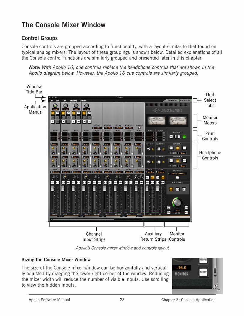
Control GroupsConsole controls are grouped according to functionality, with a layout similar to that found on typical analog mixers. The layout of these groupings is shown below. Detailed explanations of all the Console control functions are similarly grouped and presented later in this chapter.
Note: With Apollo 16, cue controls replace the headphone controls that are shown in the Apollo diagram below. However, the Apollo 16 cue controls are similarly grouped.
Apollo’s Console mixer window and controls layout
Sizing the Console Mixer Window
The size of the Console mixer window can be horizontally and vertical-ly adjusted by dragging the lower right corner of the window. Reducing the mixer width will reduce the number of visible inputs. Use scrolling to view the hidden inputs.
ChannelInput Strips
AuxiliaryReturn Strips
MonitorMeters
UnitSelectTabsApplication
Menus
WindowTitle Bar
PrintControls
HeadphoneControls
MonitorControls

Apollo Software Manual Chapter 3: Console Application 24
Scrolling
When the mixer window is sized to display fewer channels than are currently active, the window can be scrolled hori-zontally to bring the hidden channels into view. Similarly, if the window is vertically reduced by resizing, the window can be vertically scrolled to view the hidden portion.
To scroll the mixer window, use any of these methods:
• Drag the scroll bar(s) with the mouse• Click the scroll arrows at either end of the scroll bar(s)• Hover over the scroll bar(s) and use the scroll function of the input device
(scroll wheel, trackpad, etc).
Adjusting Console Controls2-state buttons, switches, and checkboxes: Click to toggle the state.
Knobs: Click-drag to adjust, or use the shortcuts below. Console’s rotary controls (and UAD plug-in knobs) can respond to Linear, Circular, or Relative Circular adjustments modes. This preference is set in the UAD Meter & Control Panel application; full details are in the UAD Sys-tem Manual.
Faders: Click-drag to adjust, or use the Console Shortcuts.
UAD Powered Plug-Ins: Most UAD plug-in controls use the same methods as above. However, some plug-in parameters may have custom controls that are unfamiliar or not obvious. All cus-tom controls are detailed for individual plug-ins in the UAD Plug-Ins Manual.
Console ShortcutsSeveral shortcuts are available to simplify Console control adjustments:
Scroll Wheel: Continuous controls (knobs and faders) can be adjusted by using the mouse scroll wheel (if available). Hover the cursor over the control and adjust the scroll wheel to modify the parameter value.
Adjust All: If the Option key is held down while modifying any control, the same control on all inputs (or aux returns) will be simultaneously adjusted. The relative difference is maintained between the same controls until any control reaches its minimum or maximum value.
Return To Default: If the Command (“⌘” or “apple” key – Mac) or Control “ctrl” key (Windows) is held when a control is clicked, the control will return to its default value. Command(Ctrl)+Option+Click will return all controls of the same type to their default value.
Mute/Solo All Toggle: Option-click a Mute or Solo button to toggle the state on all channels.
Shift+Click with Arrow Keys: After clicking a control, values can be adjusted using the arrow keys when the shift key is held down.
Button Toggle via Return: When a button has focus, it can be toggled with the return or enter keys on the computer keyboard. A button has focus after it is clicked.
Drop Menus: Menus continue to display after a single click. The mouse button does not need to be held down to view the menu.
Console mixer’s horizontal scroll bar
Apollo Software Manual Chapter 3: Console Application 25
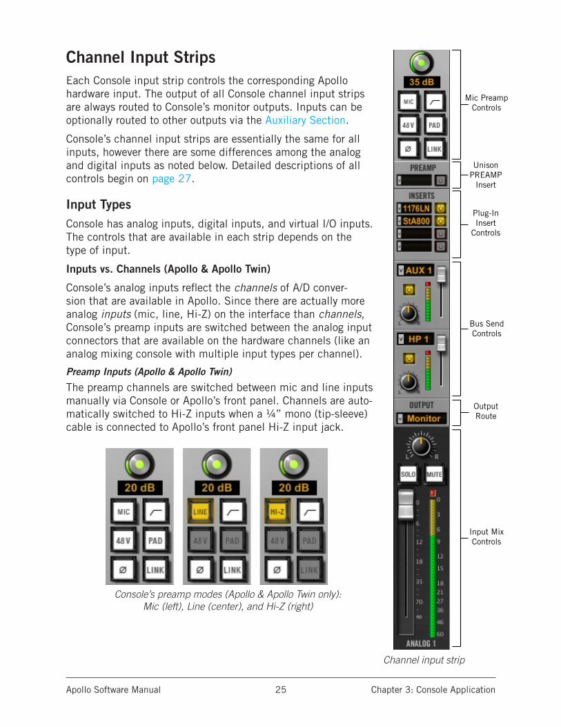
Channel Input StripsEach Console input strip controls the corresponding Apollo hardware input. The output of all Console channel input strips are always routed to Console’s monitor outputs. Inputs can be optionally routed to other outputs via the Auxiliary Section.
Console’s channel input strips are essentially the same for all inputs, however there are some differences among the analog and digital inputs as noted below. Detailed descriptions of all controls begin on page 27.
Input TypesConsole has analog inputs, digital inputs, and virtual I/O inputs. The controls that are available in each strip depends on the type of input.
Inputs vs. Channels (Apollo & Apollo Twin)
Console’s analog inputs reflect the channels of A/D conver-sion that are available in Apollo. Since there are actually more analog inputs (mic, line, Hi-Z) on the interface than channels, Console’s preamp inputs are switched between the analog input connectors that are available on the hardware channels (like an analog mixing console with multiple input types per channel).
Preamp Inputs (Apollo & Apollo Twin)
The preamp channels are switched between mic and line inputs manually via Console or Apollo’s front panel. Channels are auto-matically switched to Hi-Z inputs when a ¼” mono (tip-sleeve) cable is connected to Apollo’s front panel Hi-Z input jack.
Console’s preamp modes (Apollo & Apollo Twin only): Mic (left), Line (center), and Hi-Z (right)
Mic PreampControls
Plug-InInsert
Controls
UnisonPREAMP
Insert
Bus Send Controls
Input MixControls
OutputRoute
Channel input strip
Apollo Software Manual Chapter 3: Console Application 26
Analog Inputs (Apollo 16)
Console’s 16 analog line inputs reflect the 16 channels of A/D conversion that are avail-able in Apollo 16 (Apollo 16 does not have preamp channels).
Digital Inputs
Apollo
Console’s eight ADAT and two S/PDIF (stereo left and right) inputs work just like the ana-log inputs, except they don’t have the extra the preamp and reference level settings that are only available on the analog inputs.
Apollo Twin
Apollo Twin’s digital TOSLink input can accept ADAT or S/PDIF. Console’s inputs switch to reflect the digital input type currently in use (the digital input preference is set in the Console Settings window). The digital inputs work just like the analog inputs, except they don’t have the extra the preamp and reference level settings that are only available on the analog inputs.
Apollo 16
Console has two AES/EBU inputs (left and right). MADI inputs are not available in Con-sole (MADI on Apollo 16 is used for multi-unit cascading only).
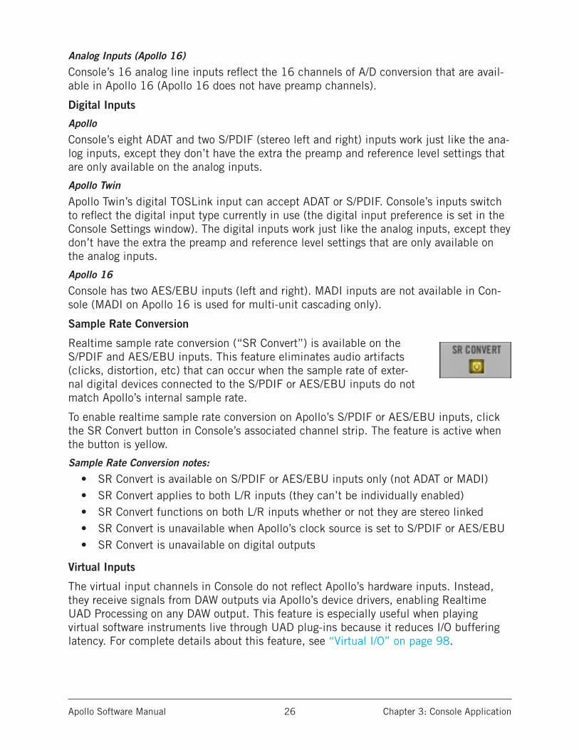
Sample Rate Conversion
Realtime sample rate conversion (“SR Convert”) is available on the S/PDIF and AES/EBU inputs. This feature eliminates audio artifacts (clicks, distortion, etc) that can occur when the sample rate of exter-nal digital devices connected to the S/PDIF or AES/EBU inputs do not match Apollo’s internal sample rate.
To enable realtime sample rate conversion on Apollo’s S/PDIF or AES/EBU inputs, click the SR Convert button in Console’s associated channel strip. The feature is active when the button is yellow.
Sample Rate Conversion notes:
• SR Convert is available on S/PDIF or AES/EBU inputs only (not ADAT or MADI)• SR Convert applies to both L/R inputs (they can’t be individually enabled)• SR Convert functions on both L/R inputs whether or not they are stereo linked• SR Convert is unavailable when Apollo’s clock source is set to S/PDIF or AES/EBU• SR Convert is unavailable on digital outputs
Virtual Inputs
The virtual input channels in Console do not reflect Apollo’s hardware inputs. Instead, they receive signals from DAW outputs via Apollo’s device drivers, enabling Realtime UAD Processing on any DAW output. This feature is especially useful when playing virtual software instruments live through UAD plug-ins because it reduces I/O buffering latency. For complete details about this feature, see “Virtual I/O” on page 98.
Apollo Software Manual Chapter 3: Console Application 27
Channel Input Controls
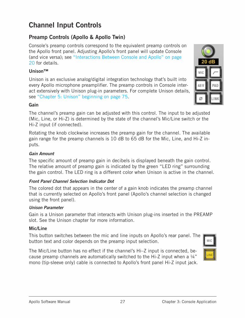
Preamp Controls (Apollo & Apollo Twin)Console’s preamp controls correspond to the equivalent preamp controls on the Apollo front panel. Adjusting Apollo’s front panel will update Console (and vice versa); see “Interactions Between Console and Apollo” on page 20 for details.
Unison™
Unison is an exclusive analog/digital integration technology that’s built into every Apollo microphone preamplifier. The preamp controls in Console inter-act extensively with Unison plug-in parameters. For complete Unison details, see “Chapter 5: Unison” beginning on page 75.
Gain
The channel’s preamp gain can be adjusted with this control. The input to be adjusted (Mic, Line, or Hi-Z) is determined by the state of the channel’s Mic/Line switch or the Hi-Z input (if connected).
Rotating the knob clockwise increases the preamp gain for the channel. The available gain range for the preamp channels is 10 dB to 65 dB for the Mic, Line, and Hi-Z in-puts.
Gain Amount
The specific amount of preamp gain in decibels is displayed beneath the gain control. The relative amount of preamp gain is indicated by the green “LED ring” surrounding the gain control. The LED ring is a different color when Unison is active in the channel.
Front Panel Channel Selection Indicator Dot
The colored dot that appears in the center of a gain knob indicates the preamp channel that is currently selected on Apollo’s front panel (Apollo’s channel selection is changed using the front panel).
Unison Parameter
Gain is a Unison parameter that interacts with Unison plug-ins inserted in the PREAMP slot. See the Unison chapter for more information.
Mic/LineThis button switches between the mic and line inputs on Apollo’s rear panel. The button text and color depends on the preamp input selection.
The Mic/Line button has no effect if the channel’s Hi–Z input is connected, be-cause preamp channels are automatically switched to the Hi-Z input when a ¼” mono (tip-sleeve only) cable is connected to Apollo’s front panel Hi-Z input jack.
Apollo Software Manual Chapter 3: Console Application 28
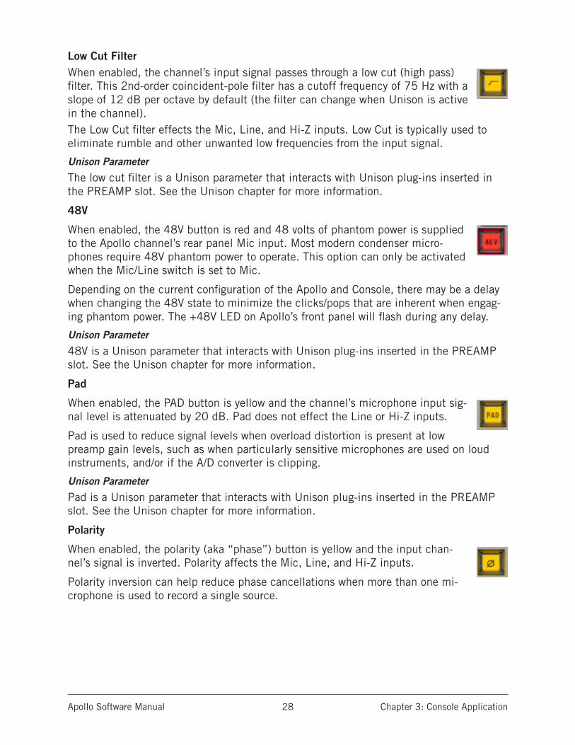
Low Cut FilterWhen enabled, the channel’s input signal passes through a low cut (high pass) filter. This 2nd-order coincident-pole filter has a cutoff frequency of 75 Hz with a slope of 12 dB per octave by default (the filter can change when Unison is active in the channel).The Low Cut filter effects the Mic, Line, and Hi-Z inputs. Low Cut is typically used to eliminate rumble and other unwanted low frequencies from the input signal.
Unison Parameter
The low cut filter is a Unison parameter that interacts with Unison plug-ins inserted in the PREAMP slot. See the Unison chapter for more information.
48V
When enabled, the 48V button is red and 48 volts of phantom power is supplied to the Apollo channel’s rear panel Mic input. Most modern condenser micro-phones require 48V phantom power to operate. This option can only be activated when the Mic/Line switch is set to Mic.
Depending on the current configuration of the Apollo and Console, there may be a delay when changing the 48V state to minimize the clicks/pops that are inherent when engag-ing phantom power. The +48V LED on Apollo’s front panel will flash during any delay.
Unison Parameter
48V is a Unison parameter that interacts with Unison plug-ins inserted in the PREAMP slot. See the Unison chapter for more information.
Pad
When enabled, the PAD button is yellow and the channel’s microphone input sig-nal level is attenuated by 20 dB. Pad does not effect the Line or Hi-Z inputs.
Pad is used to reduce signal levels when overload distortion is present at low preamp gain levels, such as when particularly sensitive microphones are used on loud instruments, and/or if the A/D converter is clipping.
Unison Parameter
Pad is a Unison parameter that interacts with Unison plug-ins inserted in the PREAMP slot. See the Unison chapter for more information.
Polarity
When enabled, the polarity (aka “phase”) button is yellow and the input chan-nel’s signal is inverted. Polarity affects the Mic, Line, and Hi-Z inputs.
Polarity inversion can help reduce phase cancellations when more than one mi-crophone is used to record a single source.
Apollo Software Manual Chapter 3: Console Application 29
Unison Parameter
Polarity is a Unison parameter that interacts with Unison plug-ins inserted in the PRE-AMP slot. See the Unison chapter for more information.
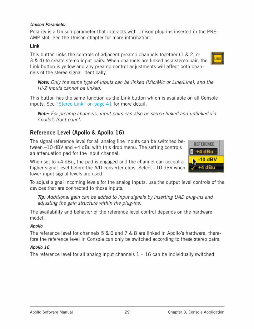
Link
This button links the controls of adjacent preamp channels together (1 & 2, or 3 & 4) to create stereo input pairs. When channels are linked as a stereo pair, the Link button is yellow and any preamp control adjustments will affect both chan-nels of the stereo signal identically.
Note: Only the same type of inputs can be linked (Mic/Mic or Line/Line), and the Hi-Z inputs cannot be linked.
This button has the same function as the Link button which is available on all Console inputs. See “Stereo Link” on page 41 for more detail.
Note: For preamp channels, input pairs can also be stereo linked and unlinked via Apollo’s front panel.
Reference Level (Apollo & Apollo 16)The signal reference level for all analog line inputs can be switched be-tween –10 dBV and +4 dBu with this drop menu. The setting controls an attenuation pad for the input channel.
When set to +4 dBu, the pad is engaged and the channel can accept a higher signal level before the A/D converter clips. Select –10 dBV when lower input signal levels are used.
To adjust signal incoming levels for the analog inputs, use the output level controls of the devices that are connected to those inputs.
Tip: Additional gain can be added to input signals by inserting UAD plug-ins and adjusting the gain structure within the plug-ins.
The availability and behavior of the reference level control depends on the hardware model:
Apollo
The reference level for channels 5 & 6 and 7 & 8 are linked in Apollo’s hardware; there-fore the reference level in Console can only be switched according to these stereo pairs.
Apollo 16
The reference level for all analog input channels 1 – 16 can be individually switched.
Apollo Software Manual Chapter 3: Console Application 30
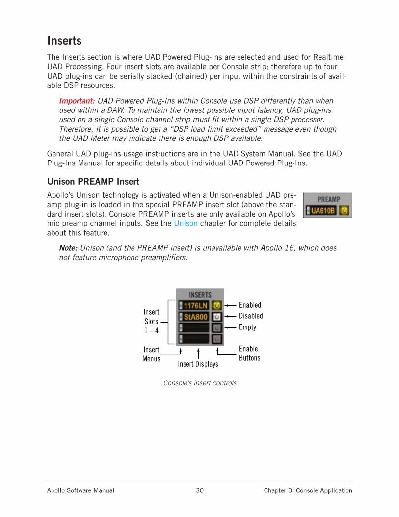
InsertsThe Inserts section is where UAD Powered Plug-Ins are selected and used for Realtime UAD Processing. Four insert slots are available per Console strip; therefore up to four UAD plug-ins can be serially stacked (chained) per input within the constraints of avail-able DSP resources.
Important: UAD Powered Plug-Ins within Console use DSP differently than when used within a DAW. To maintain the lowest possible input latency, UAD plug-ins used on a single Console channel strip must fit within a single DSP processor. Therefore, it is possible to get a “DSP load limit exceeded” message even though the UAD Meter may indicate there is enough DSP available.
General UAD plug-ins usage instructions are in the UAD System Manual. See the UAD Plug-Ins Manual for specific details about individual UAD Powered Plug-Ins.
Unison PREAMP InsertApollo’s Unison technology is activated when a Unison-enabled UAD pre-amp plug-in is loaded in the special PREAMP insert slot (above the stan-dard insert slots). Console PREAMP inserts are only available on Apollo’s mic preamp channel inputs. See the Unison chapter for complete details about this feature.
Note: Unison (and the PREAMP insert) is unavailable with Apollo 16, which does not feature microphone preamplifiers.
Console’s insert controls
EnabledDisabled
EnableButtons
InsertMenus
Insert Displays
InsertSlots1 – 4 Empty
Apollo Software Manual Chapter 3: Console Application 31
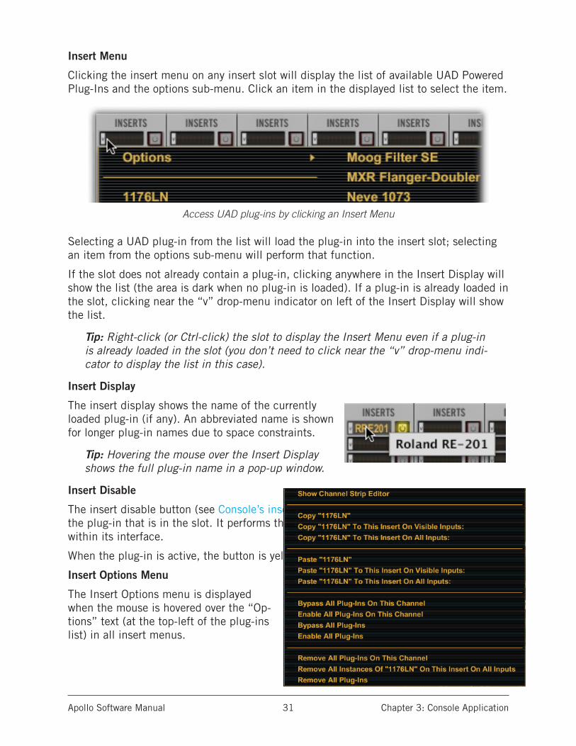
Insert Menu
Clicking the insert menu on any insert slot will display the list of available UAD Powered Plug-Ins and the options sub-menu. Click an item in the displayed list to select the item.
Access UAD plug-ins by clicking an Insert Menu
Selecting a UAD plug-in from the list will load the plug-in into the insert slot; selecting an item from the options sub-menu will perform that function.
If the slot does not already contain a plug-in, clicking anywhere in the Insert Display will show the list (the area is dark when no plug-in is loaded). If a plug-in is already loaded in the slot, clicking near the “v” drop-menu indicator on left of the Insert Display will show the list.
Tip: Right-click (or Ctrl-click) the slot to display the Insert Menu even if a plug-in is already loaded in the slot (you don’t need to click near the “v” drop-menu indi-cator to display the list in this case).
Insert Display
The insert display shows the name of the currently loaded plug-in (if any). An abbreviated name is shown for longer plug-in names due to space constraints.
Tip: Hovering the mouse over the Insert Display shows the full plug-in name in a pop-up window.
Insert Disable
The insert disable button (see Console’s insert controls) can be used to disable/re-enable the plug-in that is in the slot. It performs the same function as turning off the plug-in within its interface.
When the plug-in is active, the button is yellow. When disabled, the button is white.
Insert Options Menu
The Insert Options menu is displayed when the mouse is hovered over the “Op-tions” text (at the top-left of the plug-ins list) in all insert menus.

Apollo Software Manual Chapter 3: Console Application 32
Insert Options
The available options in the Insert Options Menu vary depending on the state of the in-sert and the copy/paste clipboard. Each Option function is described below.
Note: All copy/paste functions also copy/paste the current settings of the plug-in.
Show Channel Strip Editor – This feature (Mac only) groups and displays the interfaces of all plug-ins currently loaded in the inserts of a strip in a single window, offering a con-venient method of organizing channel plug-in windows. The single window, containing up to four plug-in GUIs, can be moved and arranged on screen as desired in a single motion.
Due to operating system differences, the Channel Strip Editor is unavailable in Windows.
Tip: To open the Channel Strip Editor, command-click any Console insert slot con-taining a UAD plug-in.
The Channel Strip Editor
Copy “Plug-In Name” – Copies the plug-in that is in the slot so it can be pasted into another slot via the Options menu “Paste” command. This option does not appear if a plug-in is not loaded in the slot.
Copy “Plug-In Name” To This Insert On Visible Inputs – Copies the plug-in that is in the slot into the same slot of all visible inputs. This option does not appear if a plug-in is not loaded in the slot.
Note: In the above context (and those below),“Visible Inputs” means all Console inputs that are currently displayed via the View Menu.
Copy “Plug-In Name” To This Insert On All Inputs – Copies the plug-in that is in the slot into the same slot of all inputs (visible or not). This option does not appear if a plug-in is not loaded in the slot.
Paste “Plug-In Name” – Pastes the plug-in (that was previously copied) into the slot. This option does not appear if a plug-in was not previously copied via the Options menu.

Apollo Software Manual Chapter 3: Console Application 33
Paste “Plug-In Name” To This Insert On Visible Inputs – Pastes the plug-in (that was previously copied) into the same slot of all visible inputs. This option does not appear if a plug-in was not previously copied via the Options menu.
Paste “Plug-In Name” To This Insert On All Inputs – Pastes the plug-in (that was previ-ously copied) into the same slot of all inputs (visible or not). This option does not appear if a plug-in was not previously copied via the Options menu.
Bypass All Plug-Ins On This Channel – Disables all plug-in processing in all slots of the channel.
Enable All Plug-Ins On This Channel – Enables all plug-in processing in all slots of the channel.
Bypass All Plug-Ins – Disables all plug-in processing on all channels.
Enable All Plug-Ins – Enables all plug-in processing on all channels.
Remove All Plug-Ins On This Channel – Unloads all plug-ins from all insert slots in the channel.
Remove All Instances of “Plug-In Name” On This Insert On All Inputs – Unloads all plug-ins that have the same name from all slots in the channel (if any).
Remove All Plug-Ins – Unloads all plug-ins from all slots in all channels.
Apollo Software Manual Chapter 3: Console Application 34
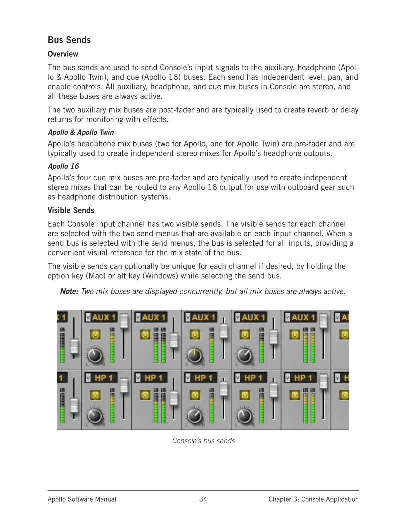
Bus SendsOverview
The bus sends are used to send Console’s input signals to the auxiliary, headphone (Apol-lo & Apollo Twin), and cue (Apollo 16) buses. Each send has independent level, pan, and enable controls. All auxiliary, headphone, and cue mix buses in Console are stereo, and all these buses are always active.
The two auxiliary mix buses are post-fader and are typically used to create reverb or delay returns for monitoring with effects.
Apollo & Apollo Twin
Apollo’s headphone mix buses (two for Apollo, one for Apollo Twin) are pre-fader and are typically used to create independent stereo mixes for Apollo’s headphone outputs.
Apollo 16
Apollo’s four cue mix buses are pre-fader and are typically used to create independent stereo mixes that can be routed to any Apollo 16 output for use with outboard gear such as headphone distribution systems.
Visible Sends
Each Console input channel has two visible sends. The visible sends for each channel are selected with the two send menus that are available on each input channel. When a send bus is selected with the send menus, the bus is selected for all inputs, providing a convenient visual reference for the mix state of the bus.
The visible sends can optionally be unique for each channel if desired, by holding the option key (Mac) or alt key (Windows) while selecting the send bus.
Note: Two mix buses are displayed concurrently, but all mix buses are always active.
Console’s bus sends
Apollo Software Manual Chapter 3: Console Application 35
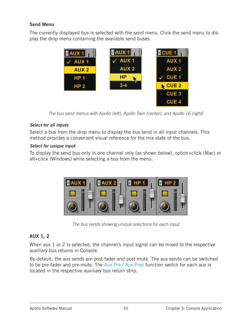
Send Menu
The currently displayed bus is selected with the send menu. Click the send menu to dis-play the drop menu containing the available send buses.
The bus send menus with Apollo (left), Apollo Twin (center), and Apollo 16 (right)
Select for all inputs
Select a bus from the drop menu to display the bus send in all input channels. This method provides a convenient visual reference for the mix state of the bus.
Select for unique input
To display the send bus only in one channel only (as shown below), option+click (Mac) or alt+click (Windows) while selecting a bus from the menu.
The bus sends showing unique selections for each input
AUX 1, 2
When aux 1 or 2 is selected, the channel’s input signal can be mixed to the respective auxiliary bus returns in Console.
By default, the aux sends are post-fader and post-mute. The aux sends can be switched to be pre-fader and pre-mute. The Aux Pre / Aux Post function switch for each aux is located in the respective auxiliary bus return strip.
Apollo Software Manual Chapter 3: Console Application 36
Note: See “Auxiliary Section” on page 42 for complete overview of Console’s aux design.
HP (Apollo & Apollo Twin)
When HP 1 or 2 is selected , the channel’s input signal can be mixed to the respective headphone bus. The headphone sends are pre-fader and mute.
Note: If the headphone source selector is set to MON, the headphone mix bus is not heard and the headphone sends have no effect.
CUE (Apollo 16)
When cue 1 – 4 is selected, the channel’s input signal can be mixed to the respective cue bus. The cue sends are pre-fader and mute
Note: If the cue source selector is set to MON, the cue mix bus is not heard and the cue sends have no effect.
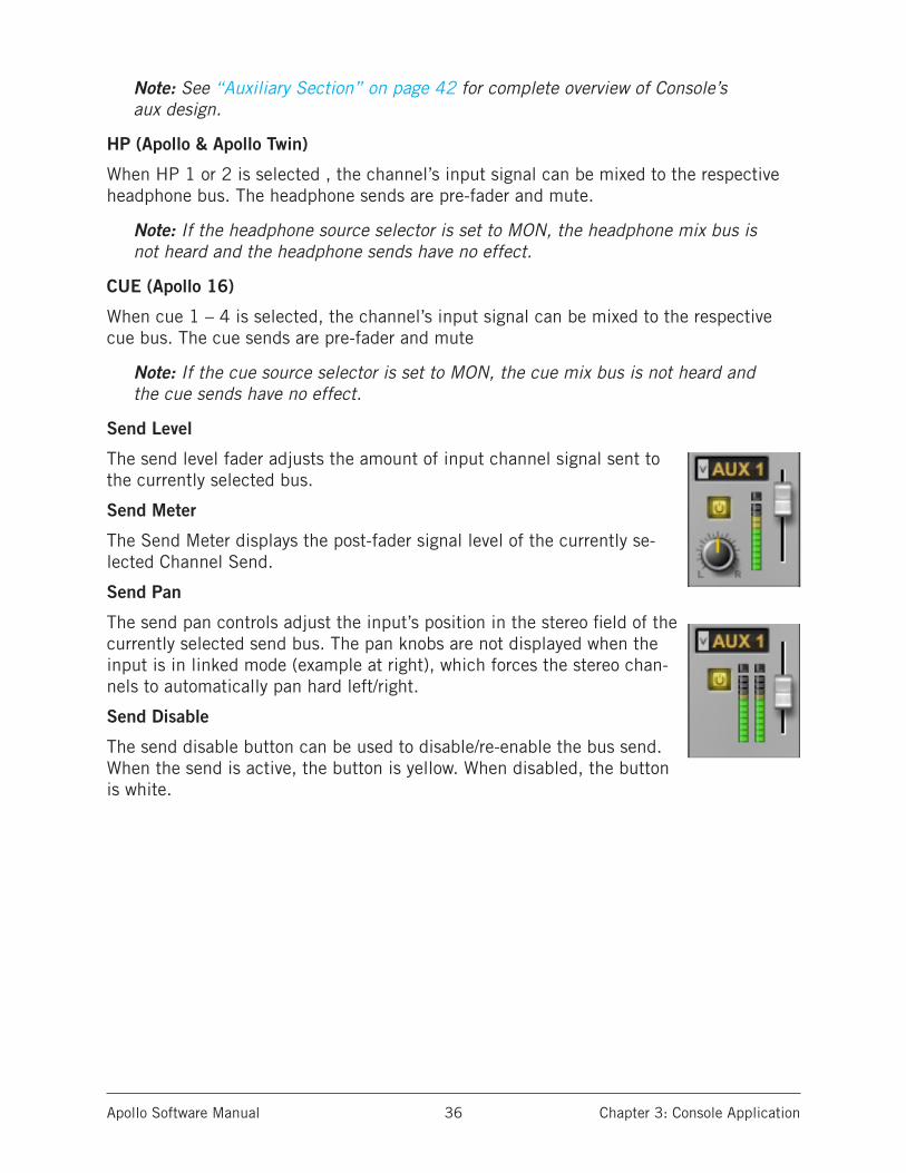
Send Level
The send level fader adjusts the amount of input channel signal sent to the currently selected bus.
Send Meter
The Send Meter displays the post-fader signal level of the currently se-lected Channel Send.
Send Pan
The send pan controls adjust the input’s position in the stereo field of the currently selected send bus. The pan knobs are not displayed when the input is in linked mode (example at right), which forces the stereo chan-nels to automatically pan hard left/right.
Send Disable
The send disable button can be used to disable/re-enable the bus send. When the send is active, the button is yellow. When disabled, the button is white.
Apollo Software Manual Chapter 3: Console Application 37
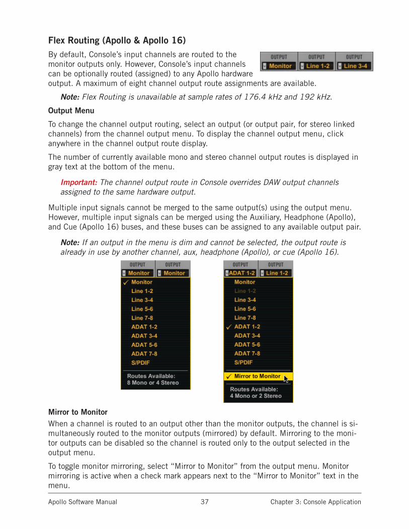
Flex Routing (Apollo & Apollo 16)By default, Console’s input channels are routed to the monitor outputs only. However, Console’s input channels can be optionally routed (assigned) to any Apollo hardware output. A maximum of eight channel output route assignments are available.
Note: Flex Routing is unavailable at sample rates of 176.4 kHz and 192 kHz.
Output Menu
To change the channel output routing, select an output (or output pair, for stereo linked channels) from the channel output menu. To display the channel output menu, click anywhere in the channel output route display.
The number of currently available mono and stereo channel output routes is displayed in gray text at the bottom of the menu.
Important: The channel output route in Console overrides DAW output channels assigned to the same hardware output.
Multiple input signals cannot be merged to the same output(s) using the output menu. However, multiple input signals can be merged using the Auxiliary, Headphone (Apollo), and Cue (Apollo 16) buses, and these buses can be assigned to any available output pair.
Note: If an output in the menu is dim and cannot be selected, the output route is already in use by another channel, aux, headphone (Apollo), or cue (Apollo 16).
Mirror to MonitorWhen a channel is routed to an output other than the monitor outputs, the channel is si-multaneously routed to the monitor outputs (mirrored) by default. Mirroring to the moni-tor outputs can be disabled so the channel is routed only to the output selected in the output menu.
To toggle monitor mirroring, select “Mirror to Monitor” from the output menu. Monitor mirroring is active when a check mark appears next to the “Mirror to Monitor” text in the menu.
Apollo Software Manual Chapter 3: Console Application 38
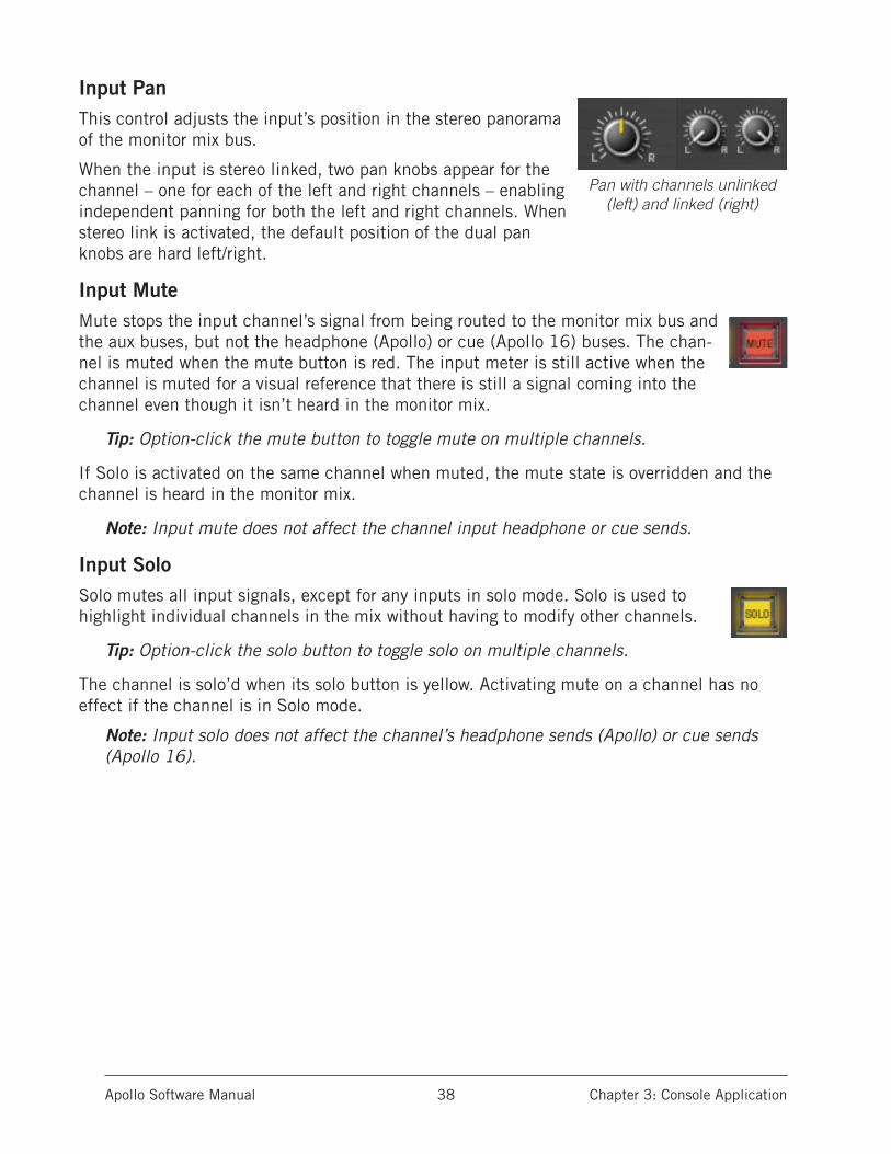
Input PanThis control adjusts the input’s position in the stereo panorama of the monitor mix bus.
When the input is stereo linked, two pan knobs appear for the channel – one for each of the left and right channels – enabling independent panning for both the left and right channels. When stereo link is activated, the default position of the dual pan knobs are hard left/right.
Input MuteMute stops the input channel’s signal from being routed to the monitor mix bus and the aux buses, but not the headphone (Apollo) or cue (Apollo 16) buses. The chan-nel is muted when the mute button is red. The input meter is still active when the channel is muted for a visual reference that there is still a signal coming into the channel even though it isn’t heard in the monitor mix.
Tip: Option-click the mute button to toggle mute on multiple channels.
If Solo is activated on the same channel when muted, the mute state is overridden and the channel is heard in the monitor mix.
Note: Input mute does not affect the channel input headphone or cue sends.
Input SoloSolo mutes all input signals, except for any inputs in solo mode. Solo is used to highlight individual channels in the mix without having to modify other channels.
Tip: Option-click the solo button to toggle solo on multiple channels.
The channel is solo’d when its solo button is yellow. Activating mute on a channel has no effect if the channel is in Solo mode.
Note: Input solo does not affect the channel’s headphone sends (Apollo) or cue sends (Apollo 16).
Pan with channels unlinked (left) and linked (right)
Apollo Software Manual Chapter 3: Console Application 39
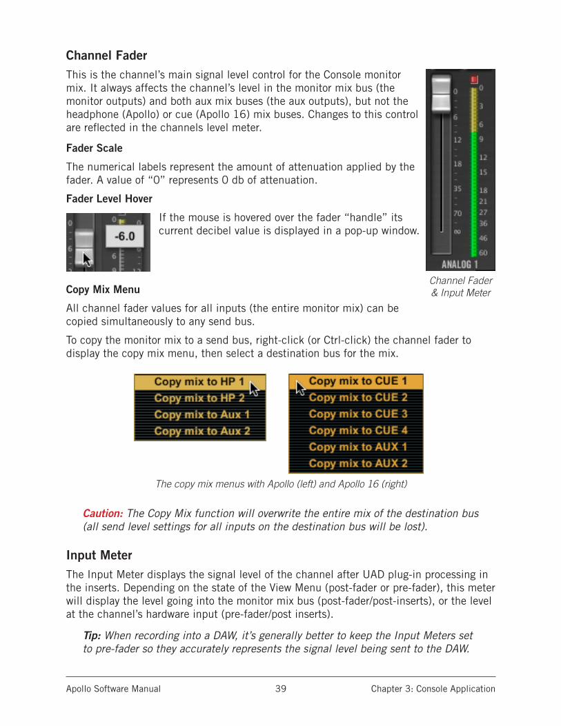
Channel FaderThis is the channel’s main signal level control for the Console monitor mix. It always affects the channel’s level in the monitor mix bus (the monitor outputs) and both aux mix buses (the aux outputs), but not the headphone (Apollo) or cue (Apollo 16) mix buses. Changes to this control are reflected in the channels level meter.
Fader Scale
The numerical labels represent the amount of attenuation applied by the fader. A value of “0” represents 0 db of attenuation.
Fader Level Hover
If the mouse is hovered over the fader “handle” its current decibel value is displayed in a pop-up window.
Copy Mix Menu
All channel fader values for all inputs (the entire monitor mix) can be copied simultaneously to any send bus.
To copy the monitor mix to a send bus, right-click (or Ctrl-click) the channel fader to display the copy mix menu, then select a destination bus for the mix.
The copy mix menus with Apollo (left) and Apollo 16 (right)
Caution: The Copy Mix function will overwrite the entire mix of the destination bus (all send level settings for all inputs on the destination bus will be lost).
Input MeterThe Input Meter displays the signal level of the channel after UAD plug-in processing in the inserts. Depending on the state of the View Menu (post-fader or pre-fader), this meter will display the level going into the monitor mix bus (post-fader/post-inserts), or the level at the channel’s hardware input (pre-fader/post inserts).
Tip: When recording into a DAW, it’s generally better to keep the Input Meters set to pre-fader so they accurately represents the signal level being sent to the DAW.
Channel Fader & Input Meter
Apollo Software Manual Chapter 3: Console Application 40
Input Level Scale
The numerical labels represent digital signal levels. “0” represents 0 dBFS (digital full scale, the maximum level before undesirable A/D clipping). If the level at the Apollo in-put exceeds 0 dBFS, the meter’s clip indicator illuminates (reduce the preamp gain and/or output level of the device feeding the input if this occurs).
These meters also have a peak hold feature, which “holds” signal peak values for a specified period of time. The clip and peak hold times can be adjusted in the Console Settings Panel.
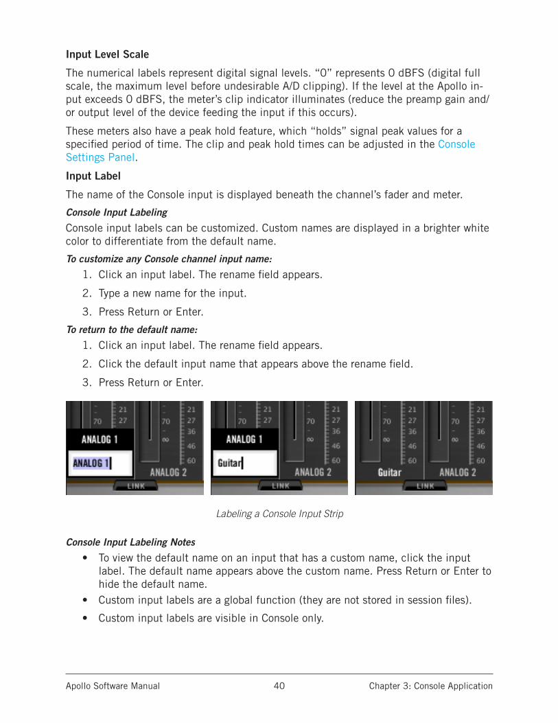
Input Label
The name of the Console input is displayed beneath the channel’s fader and meter.
Console Input Labeling
Console input labels can be customized. Custom names are displayed in a brighter white color to differentiate from the default name.
To customize any Console channel input name:
1. Click an input label. The rename field appears.
2. Type a new name for the input.
3. Press Return or Enter.
To return to the default name:
1. Click an input label. The rename field appears.
2. Click the default input name that appears above the rename field.
3. Press Return or Enter.
Labeling a Console Input Strip
Console Input Labeling Notes
• To view the default name on an input that has a custom name, click the input label. The default name appears above the custom name. Press Return or Enter to hide the default name.
• Custom input labels are a global function (they are not stored in session files).
• Custom input labels are visible in Console only.

Apollo Software Manual Chapter 3: Console Application 41
Stereo LinkAdjacent channels can be linked to create stereo input pairs by clicking the LINK button at the bottom of the channel strip. When channels are linked as a stereo pair, any control adjust-ments will affect both channels of the stereo signal identically.
Activation
Stereo pairs are created by clicking the LINK button at the bot-tom of two adjacent channel strips. For preamp channels (Apollo & Apollo Twin), clicking the LINK button within the preamp con-trols performs the exact same function pressing the LINK button on Apollo’s front panel.
Caution: All channel strip controls and plug-in settings in the right channel are overwritten when LINK is activated.
When Link is activated:• The LINK button text changes to UNLINK• One set of controls is available for the stereo channel (except
Pan, as noted below)• All current control settings of the left channel are copied to
the right channel (except Pan, as noted below)• All inserted plug-ins in the left channel are converted to ste-
reo (parameter values are retained) • The input pan knob changes to dual pan knobs• Pan values are forced to hard left and hard right• The send pan knobs are hidden from the interface (pans are
forced hard left/right stereo sends)• The Channel Meter changes to a stereo level meter
DeactivationThe stereo pair is separated back into individual channels by clicking the UNLINK button. When LINK is deactivated, all current control settings and inserted plug-ins for the stereo channel are copied to both channels (except Pan, which is centered for both channels).
Link Constraints
• Odd-numbered channels can only be linked to the next even-numbered channel (for example, Analog 1 can be linked to Analog 2, but Analog 2 cannot be linked to Analog 3).
• Only the same type of inputs can be linked (for example, an analog input can only be linked to an analog input).
• For preamp channels (Apollo & Apollo Twin), only the same input jacks can be linked (for example, a Mic input cannot be linked to a Line input).
• The Hi-Z inputs cannot be linked.
Tip: Stereo Link can be activated and deactivated on all channels simultaneously by option-clicking the stereo link button. However, use caution with this feature so all right-channel settings are not unintentionally lost.
Before and after engaging stereo LINK
Apollo Software Manual Chapter 3: Console Application 42
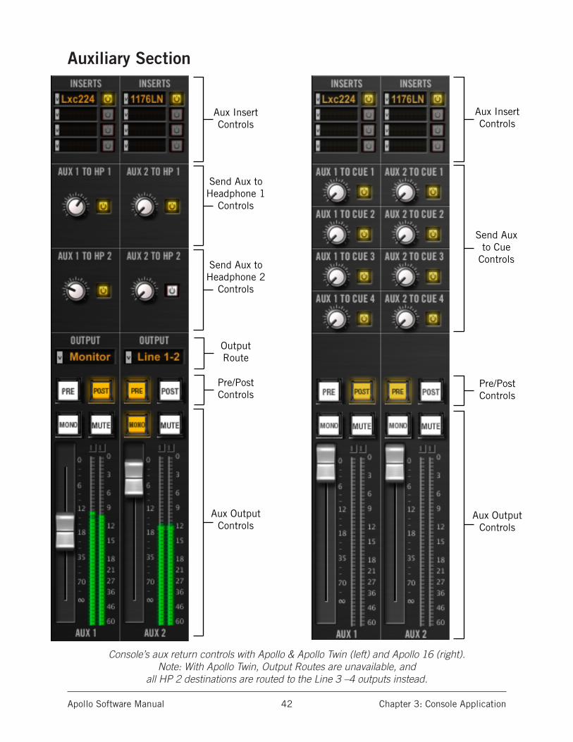
Auxiliary Section
Console’s aux return controls with Apollo & Apollo Twin (left) and Apollo 16 (right). Note: With Apollo Twin, Output Routes are unavailable, and
all HP 2 destinations are routed to the Line 3 –4 outputs instead.
Aux InsertControls
Send Aux toHeadphone 2
Controls
Send Aux toHeadphone 1
Controls
Aux OutputControls
OutputRoute
Pre/PostControls
Aux InsertControls
Send Auxto Cue
Controls
Aux OutputControls
Pre/PostControls
Apollo Software Manual Chapter 3: Console Application 43
Aux OverviewConsole has two stereo auxiliary (aux) mix buses. Signals are sent to the aux buses via the aux sends in Console’s channel input strips; Console’s aux returns then control and process the signals that are received from those sends.
The controls in Console’s aux return strips are similar to the channel input strips, but instead of controlling a channel input, they control the output of the aux mix bus. Both stereo aux returns have four insert slots for Realtime UAD Processing.
The aux sends can be post-fader and post-mute (channel faders must be up and unmut-ed to be routed to the aux bus, and the send levels will reflect channel fader changes), or pre-fader and pre-mute (channel faders and mutes do not affect the aux bus).
The aux buses in Console are designed primarily for send/return processing using UAD plug-ins. Using aux buses for effects is a great way to conserve UAD DSP resources. For example, by using an aux for reverb processing, only one reverb plug-in is needed on the aux return instead of putting a reverb plug-in on each individual channel.
Aux Notes:
• For the control descriptions, refer to the diagrams on page 42.• Aux 2 is unavailable at sample rates of 176.4 kHz and 192 kHz.• The outputs of the auxiliary buses have 32 samples of additional latency com-
pared to the monitor outputs. This is necessary to maintain the lowest possible latency for the dry signals.
• (Apollo only) Aux 2 is unavailable when multi-unit cascading.
Aux Return StripsBoth of Console’s aux return strips are identical. Most of the controls have identical functionality as their equivalent control in the channel input strips. In these cases, cross-references to the same control in the channel strips are provided instead of repeating the description.
Aux Inserts
The aux insert slots, insert menu, insert display, and insert disable buttons all have identical functionality as the channel insert controls in the input strips. See “Inserts” on page 30 for complete descriptions of the Insert controls.
Aux Headphone 1 & 2 Controls (Apollo only)
Aux Headphone 1 & 2 Send (Apollo)
The AUX TO HP knobs send the aux return to the associated headphone mix bus. There is no headphone pan knob on the aux returns, because the aux returns are stereo.
Note: When Headphone Source (page 48) s set to HP, aux returns must be sent to the headphone mix bus via these controls for the aux to be heard in the head-phones.
Apollo Software Manual Chapter 3: Console Application 44
Aux Headphone 1 & 2 Enable (Apollo)
This button can be used to disable/re-enable the aux headphone sends. When the send is active, the button is yellow. When disabled, the button is white.
Aux Headphone & Line 3–4 Controls (Apollo Twin only)
Aux Headphone & Line 3–4 Send (Apollo Twin)
The AUX TO HP and AUX to 3–4 knobs send the aux return to the associated mix bus. There is no pan knob on the aux returns, because the aux returns are stereo.
Note: When Headphone Source/Line Out 3–4 Source (page 48) is set to HP or 3–4, aux returns must be sent to the associated mix bus via these controls for the aux to be heard in the bus.
Aux Headphone/Line 3–4 Enable (Apollo Twin)
This button can be used to disable/re-enable the aux headphone and Line 3–4 sends. When the send is active, the button is yellow. When disabled, the button is white.
Aux Cue Controls (Apollo 16 only)
Aux Cue Sends (Apollo 16)
The aux returns can be routed to any of the four cue mix buses using the AUX TO CUE knobs on the aux returns. There is no cue pan knob on the aux returns, because the aux returns are stereo.
Note: When the Cue Source (page 51) is set to cue, aux returns must be sent to the cue mix bus via these controls for the aux to be heard in the cue.
Send To Cue Enable (Apollo 16)
Each aux cue send can be individually enabled. When the aux cue send is active, the button is yellow. When disabled, the button is white.
Aux Output Route (Apollo only)
Tip: The aux outputs can be virtually routed to DAW inputs via the device drivers. See “Virtual I/O” on page 98 for related information.
Apollo only
The aux returns can be routed to any pair of hardware outputs for additional routing flex-ibility. The aux output drop-menu specifies which pair of hardware outputs the aux bus is routed to. By default, the Monitor outputs are selected.
Note: If an output in the menu is dim and cannot be selected, the output route is already in use by another channel or aux.
Apollo Twin & Apollo 16 only
The aux returns are always routed to the monitor outputs.

Apollo Software Manual Chapter 3: Console Application 45
Aux Pre
When the Pre button is engaged (yellow), the aux mix bus is pre-fader and pre-mute. In Pre mode, the channel faders and mutes do not affect the aux bus.
Tip: Pre-fader mode is useful for configuring a mix bus that is completely indepen-dent from the main channel controls (for example, when creating additional cue mixes with Apollo).
Aux Post
Post-fader is the default setting for Aux 1 and 2. When the Post button is engaged (yellow), the aux mix bus is post-fader and post-mute. In Post mode, the channel faders must be up and unmuted to be routed to the aux bus, and the aux send levels will reflect channel fader changes.
Tip: Post-fader mode is typically used when configuring an effect send mix so the effect sends will interact with the main channel controls.
Aux Mono
This button sums the left and right channels of the stereo aux output into a monophonic signal. The aux return output is stereo when the button is white and mono when the but-ton is yellow.
Aux Mute
Note: Aux mute does not mute the aux bus return’s headphone sends (Apollo & Apollo Twin), Line 3–4 sends (Apollo Twin), or cue sends (Apollo 16).
Apollo only
The aux mute button stops the aux return’s signal from being routed to the output as-signed in the Aux Output Route (Apollo only) menu. The aux is muted when the mute button is red.
Apollo Twin & Apollo 16
The aux mute button stops the aux return’s signal from being routed to the monitor mix.
Aux Fader
This is the master signal level control for the aux bus return. It does not affect the aux bus return’s headphone sends (Apollo) or cue sends (Apollo 16).
Aux Meter
The Aux Meter displays the signal level of the aux bus return. The “0” label represents 0 dbFS (digital full scale, the maximum level before undesirable D/A clipping). If the level at the aux output exceeds 0 dbFS, the meter’s clip indicator illuminates (reduce the levels feeding the aux if clipping occurs).
The Aux Meters have a peak hold feature, which “holds” signal peak values for a speci-fied period of time. The clip and peak hold times can be adjusted in the Console Settings
Panel.

Apollo Software Manual Chapter 3: Console Application 46
Monitor Section
Insert Effects(”print wet”)
Control
Headphone Source
and MirrorControls
Recall(preset)Controls
MonitorControls
Insert Effects(”print wet”)
Control
Cue Sourceand Output
Controls
Recall(preset)Controls
MonitorControls
The monitor controls as they appear with Apollo & Apollo Twin (left) and Apollo 16 (right). Note: With Apollo Twin, all HP 2 destinations are routed to the Line 3 –4 outputs instead.

Apollo Software Manual Chapter 3: Console Application 47
Insert EffectsOverview
Console’s primary function is to control Apollo’s input monitoring features. Using Con-sole, Apollo’s inputs can be recorded without signal processing (dry) or with Realtime UAD processing (wet) via the Insert Effects switch.
By using Console to monitor live audio, the operator can record the Realtime UAD Pro-cessing either dry or wet without any I/O buffering and the latencies associated with software monitoring via the DAW.
Important: Unison plug-in processing in Console’s PREAMP insert is always routed to the DAW, regardless of the current Insert Effects setting (Unison PREAMP in-sert processing is always recorded). See the Unison chapter for more information.
Function of the Insert Effects Switch
The Insert Effects switch determines if the DAW records Console’s inputs with or without Realtime UAD Processing, regardless of the actual wet or dry state of the monitor mix. This is accomplished by routing Console’s inputs into the DAW from before the plug-in inserts (dry recording) or after the plug-in inserts (wet recording).
Note: Recording into a DAW with or without Realtime UAD Processing via the Insert Effects switch is a global function. The function cannot be individually enabled per input.
Record With Effects
When Record With Effects is active, Apollo’s hardware input signals are processed by Console’s UAD plug-in inserts before routing into the DAW.
In this mode, the post-insert (wet) state of all Console inputs with Realtime UAD Processing is routed to the DAW inputs.
Record With Effects is active when the Insert Effects REC button pulses red.
Note: This setting is used to record “wet” with Realtime UAD Processing.
Monitor With Effects
When Monitor With Effects is active, Apollo’s hardware input sig-nals are routed directly into the DAW before being processed by Console’s UAD plug-in inserts.
In this mode, the pre-insert (dry) state of all Console inputs is routed to the DAW inputs, even if Realtime UAD Processing is oc-curring in the monitor mix.
Record With Effects is off when the Insert Effects MON button is green.
Note: This setting is used to record “dry” when Realtime UAD Processing is active.
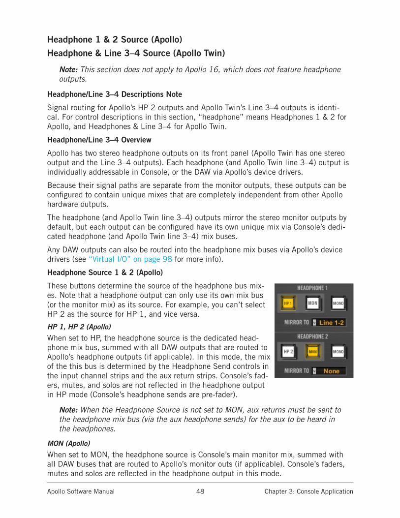
Apollo Software Manual Chapter 3: Console Application 48
Headphone 1 & 2 Source (Apollo)Headphone & Line 3–4 Source (Apollo Twin)
Note: This section does not apply to Apollo 16, which does not feature headphone outputs.
Headphone/Line 3–4 Descriptions Note
Signal routing for Apollo’s HP 2 outputs and Apollo Twin’s Line 3–4 outputs is identi-cal. For control descriptions in this section, “headphone” means Headphones 1 & 2 for Apollo, and Headphones & Line 3–4 for Apollo Twin.
Headphone/Line 3–4 Overview
Apollo has two stereo headphone outputs on its front panel (Apollo Twin has one stereo output and the Line 3–4 outputs). Each headphone (and Apollo Twin line 3–4) output is individually addressable in Console, or the DAW via Apollo’s device drivers.
Because their signal paths are separate from the monitor outputs, these outputs can be configured to contain unique mixes that are completely independent from other Apollo hardware outputs.
The headphone (and Apollo Twin line 3–4) outputs mirror the stereo monitor outputs by default, but each output can be configured have its own unique mix via Console’s dedi-cated headphone (and Apollo Twin line 3–4) mix buses.
Any DAW outputs can also be routed into the headphone mix buses via Apollo’s device drivers (see “Virtual I/O” on page 98 for more info).
Headphone Source 1 & 2 (Apollo)
These buttons determine the source of the headphone bus mix-es. Note that a headphone output can only use its own mix bus (or the monitor mix) as its source. For example, you can’t select HP 2 as the source for HP 1, and vice versa.
HP 1, HP 2 (Apollo)
When set to HP, the headphone source is the dedicated head-phone mix bus, summed with all DAW outputs that are routed to Apollo’s headphone outputs (if applicable). In this mode, the mix of the this bus is determined by the Headphone Send controls in the input channel strips and the aux return strips. Console’s fad-ers, mutes, and solos are not reflected in the headphone output in HP mode (Console’s headphone sends are pre-fader).
Note: When the Headphone Source is not set to MON, aux returns must be sent to the headphone mix bus (via the aux headphone sends) for the aux to be heard in the headphones.
MON (Apollo)
When set to MON, the headphone source is Console’s main monitor mix, summed with all DAW buses that are routed to Apollo’s monitor outs (if applicable). Console’s faders, mutes and solos are reflected in the headphone output in this mode.
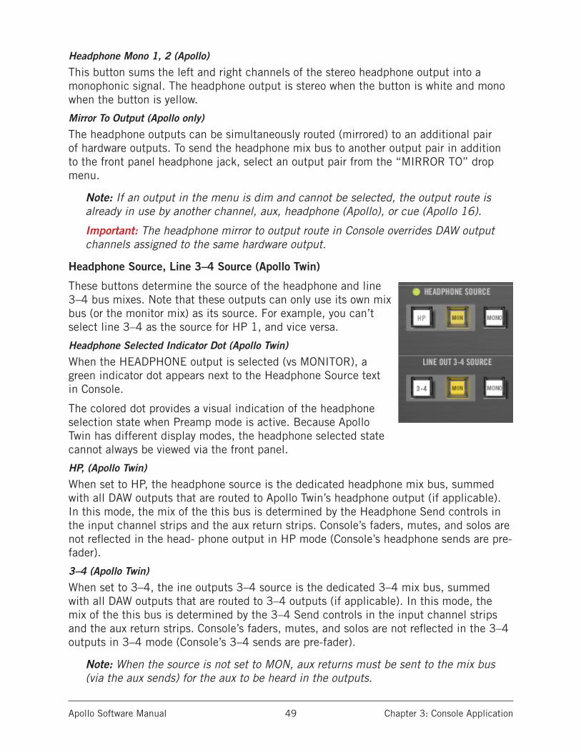
Apollo Software Manual Chapter 3: Console Application 49
Headphone Mono 1, 2 (Apollo)
This button sums the left and right channels of the stereo headphone output into a monophonic signal. The headphone output is stereo when the button is white and mono when the button is yellow.
Mirror To Output (Apollo only)
The headphone outputs can be simultaneously routed (mirrored) to an additional pair of hardware outputs. To send the headphone mix bus to another output pair in addition to the front panel headphone jack, select an output pair from the “MIRROR TO” drop menu.
Note: If an output in the menu is dim and cannot be selected, the output route is already in use by another channel, aux, headphone (Apollo), or cue (Apollo 16).
Important: The headphone mirror to output route in Console overrides DAW output channels assigned to the same hardware output.
Headphone Source, Line 3–4 Source (Apollo Twin)
These buttons determine the source of the headphone and line 3–4 bus mixes. Note that these outputs can only use its own mix bus (or the monitor mix) as its source. For example, you can’t select line 3–4 as the source for HP 1, and vice versa.
Headphone Selected Indicator Dot (Apollo Twin)
When the HEADPHONE output is selected (vs MONITOR), a green indicator dot appears next to the Headphone Source text in Console.
The colored dot provides a visual indication of the headphone selection state when Preamp mode is active. Because Apollo Twin has different display modes, the headphone selected state cannot always be viewed via the front panel.
HP, (Apollo Twin)
When set to HP, the headphone source is the dedicated headphone mix bus, summed with all DAW outputs that are routed to Apollo Twin’s headphone output (if applicable). In this mode, the mix of the this bus is determined by the Headphone Send controls in the input channel strips and the aux return strips. Console’s faders, mutes, and solos are not reflected in the head- phone output in HP mode (Console’s headphone sends are pre-fader).
3–4 (Apollo Twin)
When set to 3–4, the ine outputs 3–4 source is the dedicated 3–4 mix bus, summed with all DAW outputs that are routed to 3–4 outputs (if applicable). In this mode, the mix of the this bus is determined by the 3–4 Send controls in the input channel strips and the aux return strips. Console’s faders, mutes, and solos are not reflected in the 3–4 outputs in 3–4 mode (Console’s 3–4 sends are pre-fader).
Note: When the source is not set to MON, aux returns must be sent to the mix bus (via the aux sends) for the aux to be heard in the outputs.
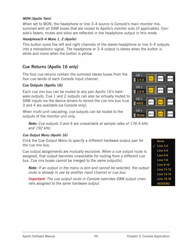
Apollo Software Manual Chapter 3: Console Application 50
MON (Apollo Twin)
When set to MON, the headphone or line 3–4 source is Console’s main monitor mix, summed with all DAW buses that are routed to Apollo’s monitor outs (if applicable). Con-sole’s faders, mutes and solos are reflected in the headphone output in this mode.
Headphone/3–4 Mono 1, 2 (Apollo)
This button sums the left and right channels of the stereo headphone or line 3–4 outputs into a monophonic signal. The headphone or 3–4 output is stereo when the button is white and mono when the button is yellow.
Cue Returns (Apollo 16 only)
The four cue returns contain the summed stereo buses from the four cue sends of each Console input channel.
Cue Outputs (Apollo 16)
Each cue mix bus can be routed to any pair Apollo 16’s hard-ware outputs. Cue 1 and 2 outputs can also be virtually routed to DAW inputs via the device drivers to record the cue mix bus (cue 3 and 4 are available via Console only).
When multi-unit cascading, cue outputs can be routed to the outputs of the monitor unit only.
Note: Cue outputs 3 and 4 are unavailable at sample rates of 176.4 kHz and 192 kHz.
Cue Output Menu (Apollo 16)
Click the Cue Output Menu to specify a different hardware output pair for the cue mix bus.
Cue output assignments are mutually exclusive. When a cue output route is assigned, that output becomes unavailable for routing from a different cue bus. Cue mix buses cannot be merged to the same output(s).
Note: If an output in the menu is dim and cannot be selected, the output route is already in use by another input channel or cue bus.
Important: The cue output route in Console overrides DAW output chan-nels assigned to the same hardware output.

Apollo Software Manual Chapter 3: Console Application 51
Cue Source (Apollo 16)
The cue source buttons determines the source of the cue bus mix. The cue source can be set to output the associated cue mix or the main monitor mix.
CUE (Apollo 16)
When set to CUE, the cue source is the dedicated cue mix, summed with all DAW out-puts that are routed to the same cue outputs (if applicable). In this mode, the mix of the cue bus is determined by the cue send controls in the input channel strips and the aux return strips.
Console’s faders, mutes, and solos are not reflected in the cue outputs in when CUE is selected (Console’s cue sends are pre-fader).
MON (Apollo 16)
When set to MON, the cue source is Console’s main monitor mix, summed with all DAW outputs that are routed to the monitor outs (if applicable). Console’s faders, mutes and solos are reflected in the cue output in this mode.
MONO (Apollo 16)
This button sums the left and right channels of the stereo cue output into a monophonic signal. The cue output is stereo when the button is white and mono when the button is yellow.
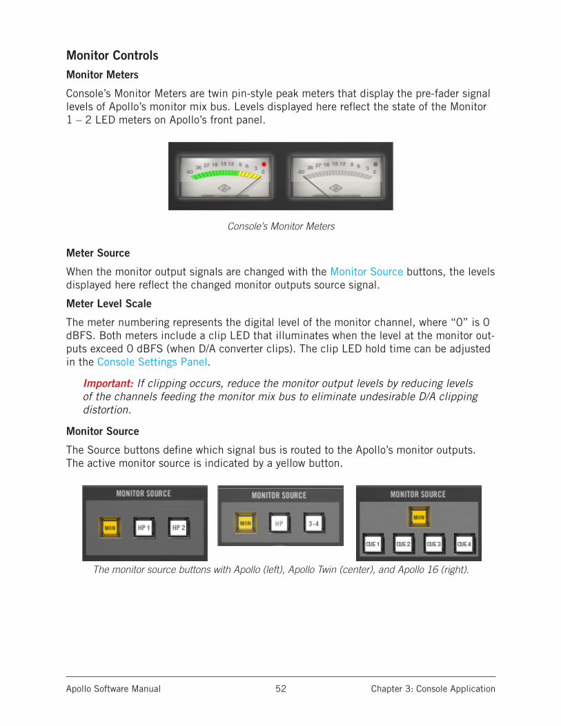
Apollo Software Manual Chapter 3: Console Application 52
Monitor ControlsMonitor Meters
Console’s Monitor Meters are twin pin-style peak meters that display the pre-fader signal levels of Apollo’s monitor mix bus. Levels displayed here reflect the state of the Monitor 1 – 2 LED meters on Apollo’s front panel.
Console’s Monitor Meters
Meter Source
When the monitor output signals are changed with the Monitor Source buttons, the levels displayed here reflect the changed monitor outputs source signal.
Meter Level Scale
The meter numbering represents the digital level of the monitor channel, where “0” is 0 dBFS. Both meters include a clip LED that illuminates when the level at the monitor out-puts exceed 0 dBFS (when D/A converter clips). The clip LED hold time can be adjusted in the Console Settings Panel.
Important: If clipping occurs, reduce the monitor output levels by reducing levels of the channels feeding the monitor mix bus to eliminate undesirable D/A clipping distortion.
Monitor Source
The Source buttons define which signal bus is routed to the Apollo’s monitor outputs. The active monitor source is indicated by a yellow button.
The monitor source buttons with Apollo (left), Apollo Twin (center), and Apollo 16 (right).
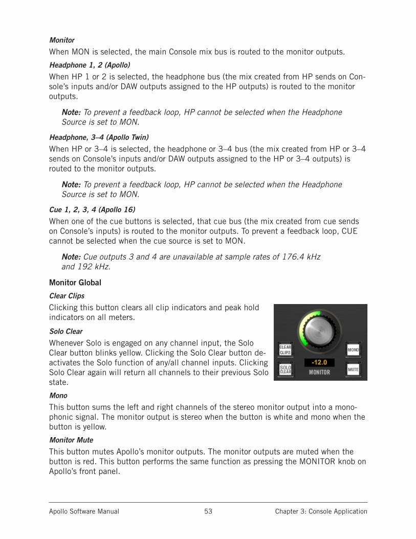
Apollo Software Manual Chapter 3: Console Application 53
Monitor
When MON is selected, the main Console mix bus is routed to the monitor outputs.
Headphone 1, 2 (Apollo)
When HP 1 or 2 is selected, the headphone bus (the mix created from HP sends on Con-sole’s inputs and/or DAW outputs assigned to the HP outputs) is routed to the monitor outputs.
Note: To prevent a feedback loop, HP cannot be selected when the Headphone Source is set to MON.
Headphone, 3–4 (Apollo Twin)
When HP or 3–4 is selected, the headphone or 3–4 bus (the mix created from HP or 3–4 sends on Console’s inputs and/or DAW outputs assigned to the HP or 3–4 outputs) is routed to the monitor outputs.
Note: To prevent a feedback loop, HP cannot be selected when the Headphone Source is set to MON.
Cue 1, 2, 3, 4 (Apollo 16)
When one of the cue buttons is selected, that cue bus (the mix created from cue sends on Console’s inputs) is routed to the monitor outputs. To prevent a feedback loop, CUE cannot be selected when the cue source is set to MON.
Note: Cue outputs 3 and 4 are unavailable at sample rates of 176.4 kHz and 192 kHz.
Monitor Global
Clear Clips
Clicking this button clears all clip indicators and peak hold indicators on all meters.
Solo Clear
Whenever Solo is engaged on any channel input, the Solo Clear button blinks yellow. Clicking the Solo Clear button de-activates the Solo function of any/all channel inputs. Clicking Solo Clear again will return all channels to their previous Solo state.
Mono
This button sums the left and right channels of the stereo monitor output into a mono-phonic signal. The monitor output is stereo when the button is white and mono when the button is yellow.
Monitor Mute
This button mutes Apollo’s monitor outputs. The monitor outputs are muted when the button is red. This button performs the same function as pressing the MONITOR knob on Apollo’s front panel.
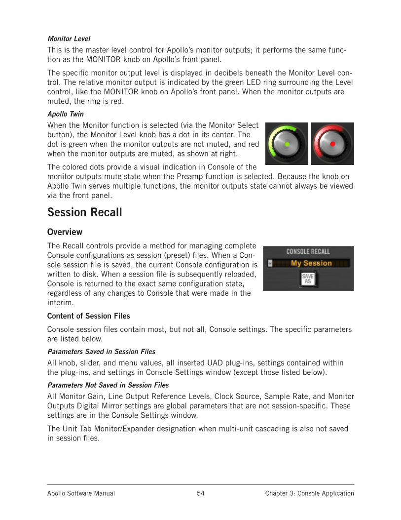
Apollo Software Manual Chapter 3: Console Application 54
Monitor Level
This is the master level control for Apollo’s monitor outputs; it performs the same func-tion as the MONITOR knob on Apollo’s front panel.
The specific monitor output level is displayed in decibels beneath the Monitor Level con-trol. The relative monitor output is indicated by the green LED ring surrounding the Level control, like the MONITOR knob on Apollo’s front panel. When the monitor outputs are muted, the ring is red.
Apollo Twin
When the Monitor function is selected (via the Monitor Select button), the Monitor Level knob has a dot in its center. The dot is green when the monitor outputs are not muted, and red when the monitor outputs are muted, as shown at right.
The colored dots provide a visual indication in Console of the monitor outputs mute state when the Preamp function is selected. Because the knob on Apollo Twin serves multiple functions, the monitor outputs state cannot always be viewed via the front panel.
Session Recall
OverviewThe Recall controls provide a method for managing complete Console configurations as session (preset) files. When a Con-sole session file is saved, the current Console configuration is written to disk. When a session file is subsequently reloaded, Console is returned to the exact same configuration state, regardless of any changes to Console that were made in the interim.
Content of Session Files
Console session files contain most, but not all, Console settings. The specific parameters are listed below.
Parameters Saved in Session Files
All knob, slider, and menu values, all inserted UAD plug-ins, settings contained within the plug-ins, and settings in Console Settings window (except those listed below).
Parameters Not Saved in Session Files
All Monitor Gain, Line Output Reference Levels, Clock Source, Sample Rate, and Monitor Outputs Digital Mirror settings are global parameters that are not session-specific. These settings are in the Console Settings window.
The Unit Tab Monitor/Expander designation when multi-unit cascading is also not saved in session files.

Apollo Software Manual Chapter 3: Console Application 55
Default Session Files Location
By default, session files are saved to, and loaded from, the user’s home folder at:
• Mac: /Users/(current user)/Documents/Universal Audio/Sessions/
• Windows: C:\Users\UserName\AppData\Roaming\Universal Audio\Sessions
Although session files can be saved to (and loaded from) any location on disk, using the default location enables the most convenience because Console always uses this location for the Open/Save dialogs presented by the operating system.
Note: Session files must reside in the default location to appear in the sessions list within the Recall Menu.
Session Files Suffix
Console’s session files have the “.uadmix” suffix. The suffix is added to session files automatically when saving to disk; however, the suffix is not displayed in the OS file save dialog (the suffix should not be manually typed when saving a session file).
Note: Without the .uadmix suffix, the session files will not be visible in the “Open” dialog windows or the Recall menu, and they won’t be opened when double-clicking them in the OS file system.
Session NameThe name of the current session is displayed in the area just below the white CONSOLE RECALL text (“My Session” as shown at right is the current session name). Session names are created when the file is saved; they can also be renamed in the OS file system.
Modified Session Name
When any Console setting is changed after the session was saved, its name appears in italics as shown at right. This is a convenient visual reminder that the session is modified and may need to be saved for future use.
SYNC Session Name
When a DAW project containing the Console Recall plug-in is opened that has the SYNC function in the plug-in en-abled, the name changes to “Sync Session” and the name is dimmed. See SYNC for related details.
SAVE AS Button
This button opens the operating system’s standard file save dialog window so a new ses-sion file can be named and saved to disk. It performs the same function as selecting “Save As...” from the Recall menu (below) or Console’s File Menu.
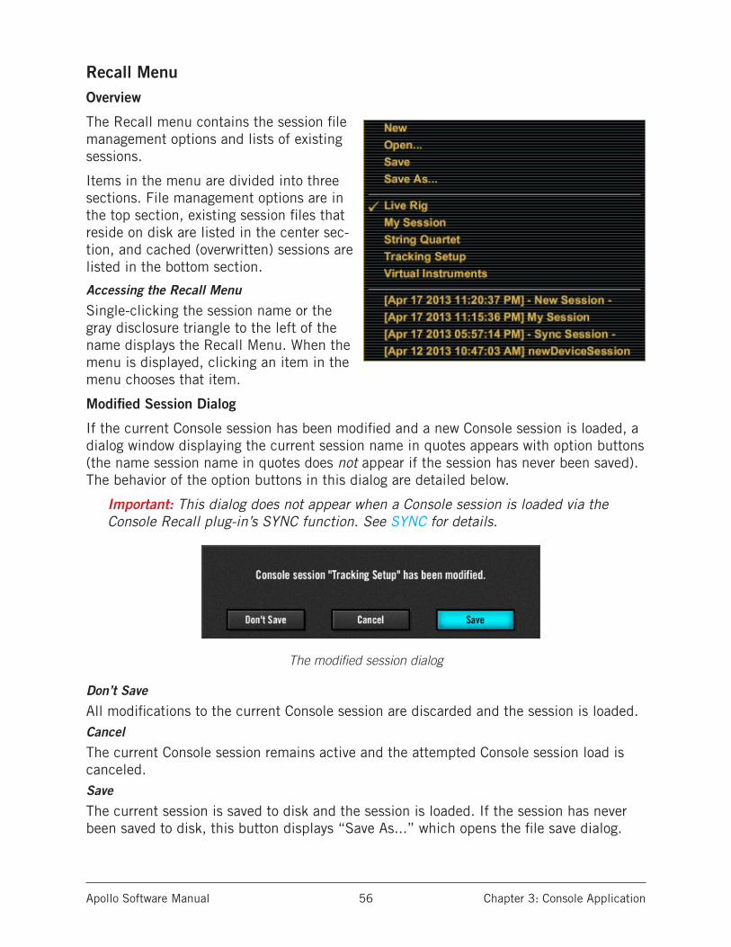
Apollo Software Manual Chapter 3: Console Application 56
Recall MenuOverview
The Recall menu contains the session file management options and lists of existing sessions.
Items in the menu are divided into three sections. File management options are in the top section, existing session files that reside on disk are listed in the center sec-tion, and cached (overwritten) sessions are listed in the bottom section.
Accessing the Recall Menu
Single-clicking the session name or the gray disclosure triangle to the left of the name displays the Recall Menu. When the menu is displayed, clicking an item in the menu chooses that item.
Modified Session Dialog
If the current Console session has been modified and a new Console session is loaded, a dialog window displaying the current session name in quotes appears with option buttons (the name session name in quotes does not appear if the session has never been saved). The behavior of the option buttons in this dialog are detailed below.
Important: This dialog does not appear when a Console session is loaded via the Console Recall plug-in’s SYNC function. See SYNC for details.
The modified session dialog
Don’t Save
All modifications to the current Console session are discarded and the session is loaded.Cancel
The current Console session remains active and the attempted Console session load is canceled.Save
The current session is saved to disk and the session is loaded. If the session has never been saved to disk, this button displays “Save As...” which opens the file save dialog.
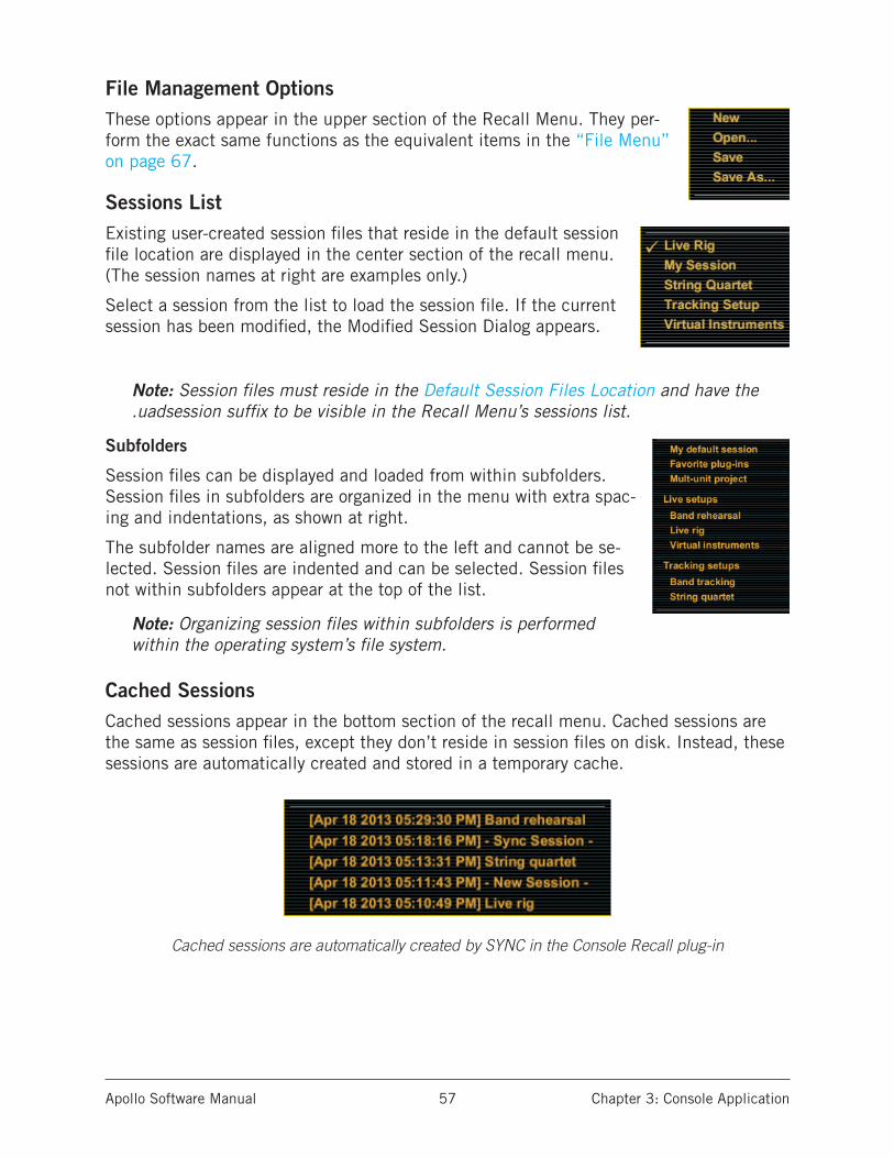
Apollo Software Manual Chapter 3: Console Application 57
File Management OptionsThese options appear in the upper section of the Recall Menu. They per-form the exact same functions as the equivalent items in the “File Menu” on page 67.
Sessions ListExisting user-created session files that reside in the default session file location are displayed in the center section of the recall menu. (The session names at right are examples only.)
Select a session from the list to load the session file. If the current session has been modified, the Modified Session Dialog appears.
Note: Session files must reside in the Default Session Files Location and have the .uadsession suffix to be visible in the Recall Menu’s sessions list.
Subfolders
Session files can be displayed and loaded from within subfolders. Session files in subfolders are organized in the menu with extra spac-ing and indentations, as shown at right.
The subfolder names are aligned more to the left and cannot be se-lected. Session files are indented and can be selected. Session files not within subfolders appear at the top of the list.
Note: Organizing session files within subfolders is performed within the operating system’s file system.
Cached SessionsCached sessions appear in the bottom section of the recall menu. Cached sessions are the same as session files, except they don’t reside in session files on disk. Instead, these sessions are automatically created and stored in a temporary cache.
Cached sessions are automatically created by SYNC in the Console Recall plug-in

Apollo Software Manual Chapter 3: Console Application 58
Why They Exist
When a DAW project containing the Console Recall plug-in is opened and the plug-in’s SYNC function is enabled, the Console settings contained in the DAW project overwrite the current Console settings. The cached sessions are used to recover the overwritten data if desired. See SYNC for details about the feature.
When They Appear
A cached session is automatically created every time a DAW project containing the Con-sole Recall plug-in is opened and the plug-in’s SYNC function is enabled. In this scenar-io, the SYNC function loads the Console session contained in the DAW project, and the previously-active Console settings are moved into the cached sessions menu.
The previously-saved Console session’s filename is retained in the cached session, and a timestamp is prefixed so it can be easily distinguished from other sessions. The five most-recently cached sessions appear in the list.
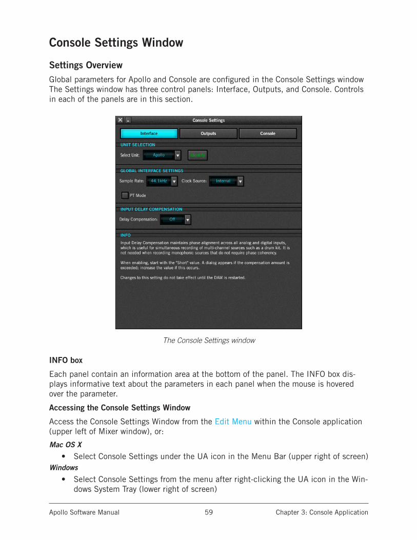
Apollo Software Manual Chapter 3: Console Application 59
Console Settings Window
Settings Overview Global parameters for Apollo and Console are configured in the Console Settings window The Settings window has three control panels: Interface, Outputs, and Console. Controls in each of the panels are in this section.
The Console Settings window
INFO box
Each panel contain an information area at the bottom of the panel. The INFO box dis-plays informative text about the parameters in each panel when the mouse is hovered over the parameter.
Accessing the Console Settings Window
Access the Console Settings Window from the Edit Menu within the Console application (upper left of Mixer window), or:
Mac OS X
• Select Console Settings under the UA icon in the Menu Bar (upper right of screen)Windows
• Select Console Settings from the menu after right-clicking the UA icon in the Win-dows System Tray (lower right of screen)

Apollo Software Manual Chapter 3: Console Application 60
Interface Settings PanelThe Interface panel is used to configure Apollo’s system-level audio interface I/O settings such as sample rate, clock source, and output reference levels. These settings are used by host applications when they are configured to use Apollo as the audio interface. Even when Console is not open, these settings are stored by the Apollo drivers and will be used by other host applications.
The Interface panel within the Console Settings window
Unit Selection
Tip: The Unit Selection functions can also be performed in the Console Mixer by right-clicking the Unit Tabs (at upper right of the Console Mixer window).
Select Unit
This menu specifies the unit for the Identify function (see below) when multi-unit cas-cading. Click the triangle to the right of the unit name to display the drop menu and select a different unit. This feature is only applicable when using a supported multi-unit configuration.
Rename Unit
The default unit name can be changed. To change the unit name: Click the unit name field, enter the new name, then click outside the field or press return on the computer keyboard.
Note: Text in this field is red when Apollo is not detected.
Identify
Clicking the Identify button will cause the currently selected unit’s front panel LEDs to flash in a pattern. This identifies the unit that is currently being controlled by Console (the current unit is changed with the Select Unit menu).
Note: This button is red when Apollo is not detected.

Apollo Software Manual Chapter 3: Console Application 61
Host Status
When the Apollo drivers are not properly communicating with the Apollo hardware, text in the Unit Selection section appears in red. Check software installation and connections if this occurs.
Global Interface Settings
Behavior and control of the Global Interface Settings depend on the environment:
Without a DAW – Sample Rate and Clock Source settings define the active sample rate and clock source for Apollo when a DAW is not used (when Console is the only host ap-plication). PT Mode has no effect when audio applications (other than Console) are not used.
With a DAW – These settings are usually changed within the DAW application’s audio preferences.
Note: PT Mode changes the driver I/O complement, therefore it affects all DAWs under both Mac and Windows. See “PT Mode” on page 100 for details.
Sample Rate
Defines the sample rate that will be used for Apollo A/D and D/A conversion and UAD Powered Plug-Ins processing. When using UAD Powered Plug-Ins, higher sample rates require more UAD DSP resources.
Important: When the Clock Source parameter is set to use any external clock source, the sample rate must be manually set to match the sample rate of the external clock.
Apollo Twin Note: If the current digital input setting is S/PDIF and the sample rate is changed to a rate higher than 96 kHz, the clock source is changed to Internal and the S/PDIF inputs are no longer unavailable.
Clock Source
Sets the master clock source for A/D and D/A conversion. The available options are:
Apollo – Internal clock or external clock from S/PDIF, ADAT, or Word Clock.
Apollo Twin – Internal clock or external clock from S/PDIF or ADAT.
Apollo 16 – Internal clock or external clock from AES/EBU or Word Clock.
If the Clock Source setting is not set to Internal and the external clock signal is not detected, then the text in the Clock Source display is RED (if this occurs, verify connec-tions and external clock device settings).
Note: Only one device in a system can be the master clock. This setting must match the host DAW setting or audio glitches and/or distortion could occur.
Digital Input (Apollo Twin only)
This menu selects the digital input type (ADAT or S/PDIF) to be used by Apollo Twin’s TOSLINK optical connector. Click the field to display the drop menu and select a differ-ent digital input source.

Apollo Software Manual Chapter 3: Console Application 62
Apollo Twin supports S/PDIF digital input at sample rates up to 96 kHz. If the current setting is ADAT and the sample rate is higher than 96 kHz, when S/PDIF input is select-ed, the clock source is changed to Internal and the S/PDIF inputs are no longer unavail-able.
Buffer Size (Windows only)
This menu determines the audio interface hardware I/O buffer size. On Mac systems, the I/O buffer size is changed within the DAW audio preferences.
PT Mode (Apollo & Apollo 16 only)
PT Mode facilitates Pro Tools’ Hardware Inserts feature by inserting NULL (empty) values at inputs 1 & 2 so input/output numbering within Pro Tools is aligned. This setting also optimizes Apollo’s I/O channels to accommodate the 32 I/O channels available in Pro Tools.
PT Mode only affects operation with host audio applications that can address an audio interface’s individual I/O. The setting does not affect use with Console.
See “PT Mode” on page 100 for complete details about this feature.
Important: Enabling PT Mode changes the driver I/O complement. Quit all audio applications before changing the PT Mode setting.
Input Delay Compensation
Input Delay Compensation (IDC) maintains phase alignment across Console’s analog and digital inputs when upsampled UAD plug-ins are used. See “Input Delay Compensation in Console” on page 111 for a complete explanation of this feature.
When enabling IDC, it’s usually best to start with the Short value (100 samples – the default value) to mini-mize latency.
A dialog will appear in Console if the compensation amount is exceeded on a channel. If this occurs, either increase the IDC value or reduce upsampled plug-ins usage on the channel to maintain phase alignment.
Note: Changes to this setting do not take effect until the DAW is quit.
Input Delay Compensation Values
Setting Name Extra Delay (samples)
Off 0
Short 100
Medium 200
Long 1000

Apollo Software Manual Chapter 3: Console Application 63
Outputs Settings PanelThe Outputs panel is used to configure the global behavior of the hardware outputs.
The Outputs panel within the Console Settings window
Monitor Outputs
S/PDIF Mirrors Monitor 1–2 (Apollo only)AES/EBU Mirrors Monitor 1–2 (Apollo 16 only)
This setting configures the S/PDIF (Apollo) or AES/EBU (Apollo 16) outputs to mirror the Monitor 1 & 2 outputs. This feature can be useful when connecting to the stereo inputs of other devices with digital inputs such as a speaker system, stereo recorder, or external D/A converter.
When Mirror mode is active, the Monitor Level knob controls both the digital output level and the analog monitor output level (these digital outputs are post-fader when mirrored).
Note: When this box is checked, any DAW outputs and/or Console aux outputs that are routed to these digital ports will not be heard, because the digital ports are switched to output the monitor bus instead.
Operating Level (Apollo Twin & Apollo 16 only)
This menu switches the operating level of the monitor out-puts. Available selections are 20 dBu and 14 dBu.
Line Output Reference Levels
These drop menus set the reference level for the line outputs. The number of menus dis-played depends on the currently connected Apollo hardware (multiple units and/or Apollo 16 will display more menus). The name of unit(s) the from the Rename Unit field are reflected here to identify the outputs.
The line output reference levels can be set to –10 dBV or +4 dBu in adjacent pairs. The value is usually set to match the nominal input level of devices connected to these out-puts (a setting of +4 dBu outputs a higher signal level than –10 dBV).
Note: Input reference levels for the analog line inputs are set in Console’s channel input strips.
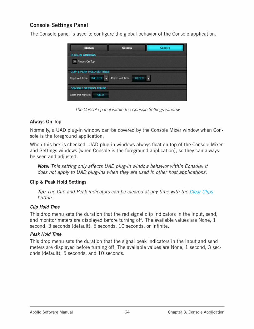
Apollo Software Manual Chapter 3: Console Application 64
Console Settings PanelThe Console panel is used to configure the global behavior of the Console application.
The Console panel within the Console Settings window
Always On Top
Normally, a UAD plug-in window can be covered by the Console Mixer window when Con-sole is the foreground application.
When this box is checked, UAD plug-in windows always float on top of the Console Mixer and Settings windows (when Console is the foreground application), so they can always be seen and adjusted.
Note: This setting only affects UAD plug-in window behavior within Console; it does not apply to UAD plug-ins when they are used in other host applications.
Clip & Peak Hold Settings
Tip: The Clip and Peak indicators can be cleared at any time with the Clear Clips button.
Clip Hold Time
This drop menu sets the duration that the red signal clip indicators in the input, send, and monitor meters are displayed before turning off. The available values are None, 1 second, 3 seconds (default), 5 seconds, 10 seconds, or Infinite.
Peak Hold Time
This drop menu sets the duration that the signal peak indicators in the input and send meters are displayed before turning off. The available values are None, 1 second, 3 sec-onds (default), 5 seconds, and 10 seconds.
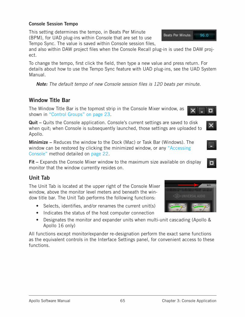
Apollo Software Manual Chapter 3: Console Application 65
Console Session Tempo
This setting determines the tempo, in Beats Per Minute (BPM), for UAD plug-ins within Console that are set to use Tempo Sync. The value is saved within Console session files, and also within DAW project files when the Console Recall plug-in is used the DAW proj-ect.
To change the tempo, first click the field, then type a new value and press return. For details about how to use the Tempo Sync feature with UAD plug-ins, see the UAD System Manual.
Note: The default tempo of new Console session files is 120 beats per minute.
Window Title BarThe Window Title Bar is the topmost strip in the Console Mixer window, as shown in “Control Groups” on page 23.
Quit – Quits the Console application. Console’s current settings are saved to disk when quit; when Console is subsequently launched, those settings are uploaded to Apollo.
Minimize – Reduces the window to the Dock (Mac) or Task Bar (Windows). The window can be restored by clicking the minimized window, or any “Accessing Console” method detailed on page 22.
Fit – Expands the Console Mixer window to the maximum size available on display monitor that the window currently resides on.
Unit TabThe Unit Tab is located at the upper right of the Console Mixer window, above the monitor level meters and beneath the win-dow title bar. The Unit Tab performs the following functions:
• Selects, identifies, and/or renames the current unit(s)• Indicates the status of the host computer connection• Designates the monitor and expander units when multi-unit cascading (Apollo &
Apollo 16 only)
All functions except monitor/expander re-designation perform the exact same functions as the equivalent controls in the Interface Settings panel, for convenient access to these functions.
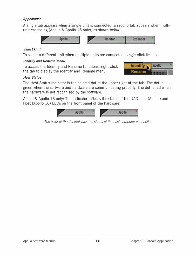
Apollo Software Manual Chapter 3: Console Application 66
Appearance
A single tab appears when a single unit is connected; a second tab appears when multi-unit cascading (Apollo & Apollo 16 only), as shown below.
Select Unit
To select a different unit when multiple units are connected, single-click its tab.
Identify and Rename Menu
To access the Identify and Rename functions, right-click the tab to display the Identify and Rename menu.
Host Status
The Host Status indicator is the colored dot at the upper right of the tab. The dot is green when the software and hardware are communicating properly. The dot is red when the hardware is not recognized by the software.
Apollo & Apollo 16 only: The indicator reflects the status of the UAD Link (Apollo) and Host (Apollo 16) LEDs on the front panel of the hardware.
The color of the dot indicates the status of the host computer connection

Apollo Software Manual Chapter 3: Console Application 67
Application MenusThe Applications Menus are contained within the second strip from the top in the Con-sole Mixer window (see “Control Groups” on page 23).
Console’s Application Menus
File Menu
Console’s File Menu contents
New Session
Creates a new Console session with default settings (default settings cannot be changed). If the current session has been modified, the Modified Session Dialog appears.
Open Session...
Opens the operating system’s standard “Open File” dialog window for loading existing session files from disk. Session files can also be opened by double-clicking .uadmix files from within the OS’s file system.
Caution: All current Console settings are overwritten (and lost, if not previously saved) when Console sessions are loaded.
Save Session
If a session file was previously saved, selecting this option writes the current settings to the file with the same name, overwriting the previously saved file. If the current session has never been saved, the operating system’s standard “Save File” dialog window ap-pears so a new session file can be named and saved to disk.
Save Session As...
This option opens the operating system’s standard “Save File” dialog window so a new session file can be named and saved to disk.
Important: Session settings will not be saved if the “/” (forward slash) or “?” (question mark) characters are in the filename. Avoid these characters when sav-ing session files.
Apollo
Apollo 16

Apollo Software Manual Chapter 3: Console Application 68
Edit Menu
Console’s Edit Menu contents
Undo
When a parameter value in the Console Mixer window is edited, the change can be re-verted with the Undo command. Only the last edit performed can be reverted with this command.
Redo
When the Undo function (above) is executed, the original edit can be restored with the Redo command. Only the last Undo performed can be restored with this command.
Note: Undo/Redo are unavailable for plug-in instantiations and parameter edits within plug-in windows, and also when using key modifiers to link/unlink channel parameters (including linear and discrete controls).
Settings
Selecting this option opens the Console Settings window, where various global param-eters are configured. See “Console Settings Window” on page 59 for details about the window.
View MenuThe View Menu provides a convenient way to hide channel strips of a particular type from view. This feature reduces screen space required by Console and/or the need for scrolling (if the window size is reduced), or when particular input types are not being used.
Note: Availability of items in this menu reflect the hard-ware and settings available with each Apollo model.
A check mark indicates channel input strips of that type (Analog, Digital, Virtual) are displayed. Choose an item in the menu to un-check the item. Choose the item again to re-check it and restore the inputs for viewing.
Note: All input channels remain active even if they are hidden from view.
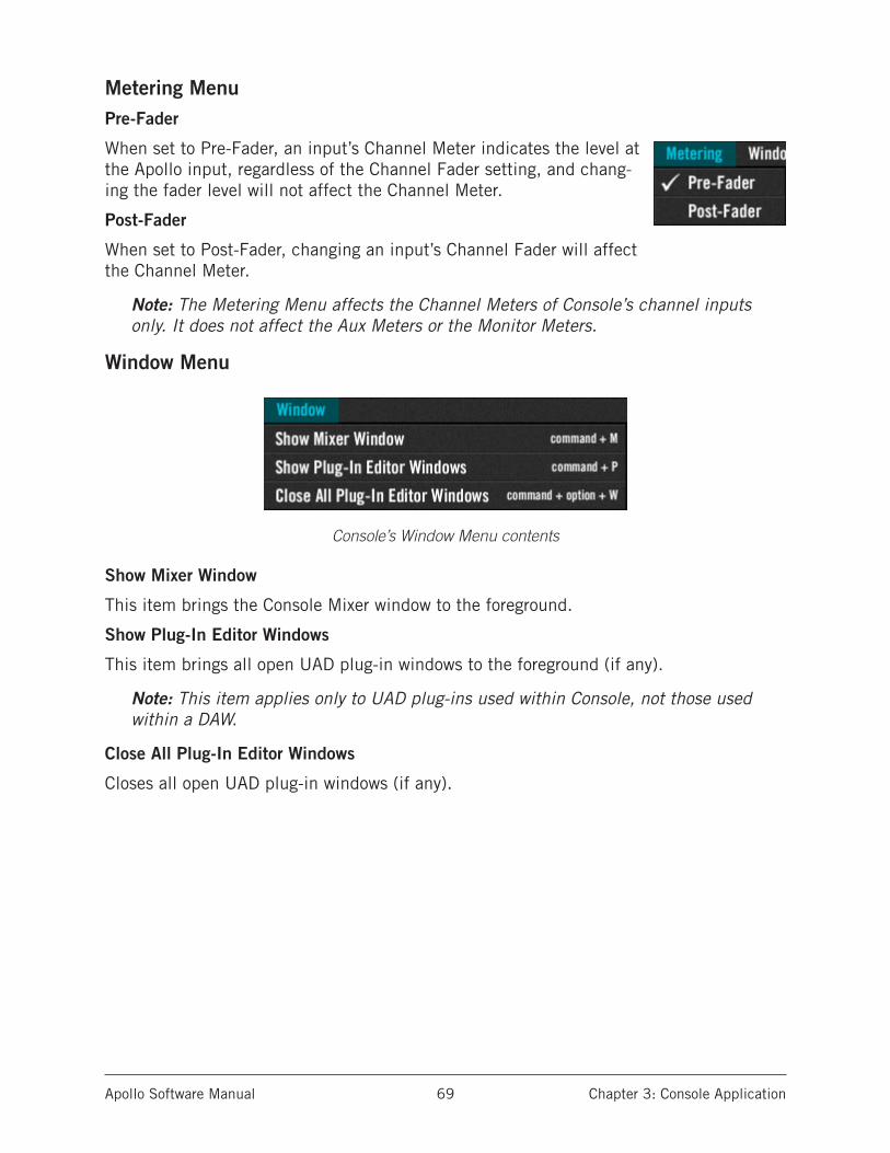
Apollo Software Manual Chapter 3: Console Application 69
Metering MenuPre-Fader
When set to Pre-Fader, an input’s Channel Meter indicates the level at the Apollo input, regardless of the Channel Fader setting, and chang-ing the fader level will not affect the Channel Meter.
Post-Fader
When set to Post-Fader, changing an input’s Channel Fader will affect the Channel Meter.
Note: The Metering Menu affects the Channel Meters of Console’s channel inputs only. It does not affect the Aux Meters or the Monitor Meters.
Window Menu
Console’s Window Menu contents
Show Mixer Window
This item brings the Console Mixer window to the foreground.
Show Plug-In Editor Windows
This item brings all open UAD plug-in windows to the foreground (if any).
Note: This item applies only to UAD plug-ins used within Console, not those used within a DAW.
Close All Plug-In Editor Windows
Closes all open UAD plug-in windows (if any).
Apollo Software Manual Chapter 3: Console Application 70
Help Menu
Console’s Help Menu contents
Open Documentation Folder
This item opens the folder containing all the Apollo product user documentation files. Consult the documentation when you need specific operational information.
After opening the folder, double-click a documentation file to open it.
Tip: Use the search function within the PDF reader application to quickly find information about a particular topic.
Contents of the documentation folder:
• Apollo Hardware Manuals (Apollo, Apollo Twin, Apollo 16)• Apollo Software Manual• UAD System Manual• UAD Plug-Ins Manual• Direct Developer (3rd-party) plug-in manuals
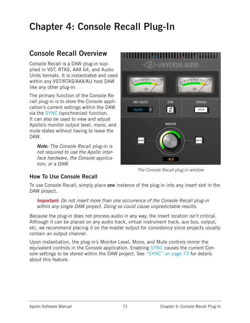
Apollo Software Manual Chapter 4: Console Recall Plug-In 71
Chapter 4: Console Recall Plug-In
Console Recall OverviewConsole Recall is a DAW plug-in sup-plied in VST, RTAS, AAX 64, and Audio Units formats. It is instantiated and used within any VST/RTAS/AAX/AU host DAW like any other plug-in.
The primary function of the Console Re-call plug-in is to store the Console appli-cation’s current settings within the DAW via the SYNC (synchronize) function. It can also be used to view and adjust Apollo’s monitor output level, mono, and mute states without having to leave the DAW.
Note: The Console Recall plug-in is not required to use the Apollo inter-face hardware, the Console applica-tion, or a DAW.
How To Use Console RecallTo use Console Recall, simply place one instance of the plug-in into any insert slot in the DAW project.
Important: Do not insert more than one occurrence of the Console Recall plug-in within any single DAW project. Doing so could cause unpredictable results.
Because the plug-in does not process audio in any way, the insert location isn’t critical. Although it can be placed on any audio track, virtual instrument track, aux bus, output, etc, we recommend placing it on the master output for consistency since projects usually contain an output channel.
Upon instantiation, the plug-in’s Monitor Level, Mono, and Mute controls mirror the equivalent controls in the Console application. Enabling SYNC causes the current Con-sole settings to be stored within the DAW project. See “SYNC” on page 73 for details about this feature.
The Console Recall plug-in window

Apollo Software Manual Chapter 4: Console Recall Plug-In 72
Console Recall Controls
Console Recall plug-In controls layout
Most Console Recall plug-in controls are duplicates of those found in the Console appli-cation. The exceptions are the SYNC button, which is detailed beginning on page 73, and the OPEN CONSOLE button, which opens the Console Mixer window.
Because the exact same control descriptions in the Console application apply to the Con-sole Recall plug-in controls, please refer to the Console application chapter for descrip-tions of the duplicated controls.
Control GroupingsThe diagram above illustrates the control groupings in Console Recall. These are the same groupings detailed in the Console chapter; click the hyperlinks below to jump to that section.
• Monitor Meters – Refer to page 52
• Monitor Controls – Refer to page 52
• Unit Select – Refer to page 60
SYNCSwitch
MonitorMeters
OpenConsoleButton
UnitSelect
MonitorControls
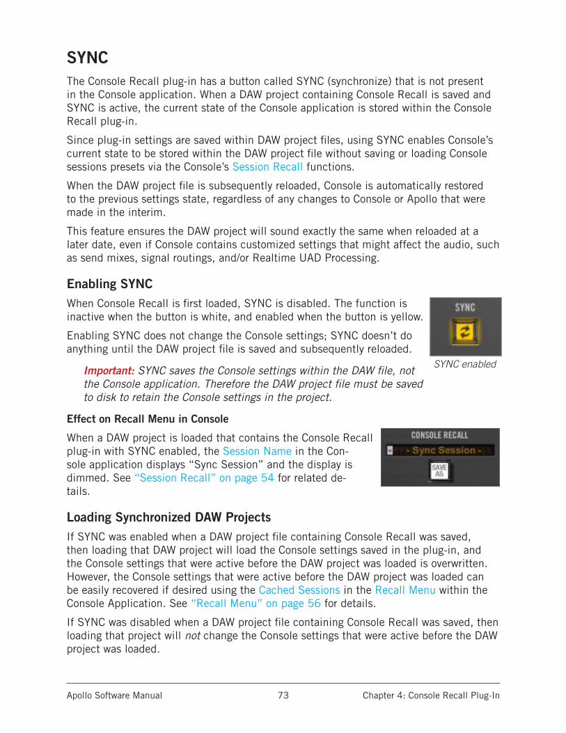
Apollo Software Manual Chapter 4: Console Recall Plug-In 73
SYNCThe Console Recall plug-in has a button called SYNC (synchronize) that is not present in the Console application. When a DAW project containing Console Recall is saved and SYNC is active, the current state of the Console application is stored within the Console Recall plug-in.
Since plug-in settings are saved within DAW project files, using SYNC enables Console’s current state to be stored within the DAW project file without saving or loading Console sessions presets via the Console’s Session Recall functions.
When the DAW project file is subsequently reloaded, Console is automatically restored to the previous settings state, regardless of any changes to Console or Apollo that were made in the interim.
This feature ensures the DAW project will sound exactly the same when reloaded at a later date, even if Console contains customized settings that might affect the audio, such as send mixes, signal routings, and/or Realtime UAD Processing.
Enabling SYNCWhen Console Recall is first loaded, SYNC is disabled. The function is inactive when the button is white, and enabled when the button is yellow.
Enabling SYNC does not change the Console settings; SYNC doesn’t do anything until the DAW project file is saved and subsequently reloaded.
Important: SYNC saves the Console settings within the DAW file, not the Console application. Therefore the DAW project file must be saved to disk to retain the Console settings in the project.
Effect on Recall Menu in Console
When a DAW project is loaded that contains the Console Recall plug-in with SYNC enabled, the Session Name in the Con-sole application displays “Sync Session” and the display is dimmed. See “Session Recall” on page 54 for related de-tails.
Loading Synchronized DAW ProjectsIf SYNC was enabled when a DAW project file containing Console Recall was saved, then loading that DAW project will load the Console settings saved in the plug-in, and the Console settings that were active before the DAW project was loaded is overwritten. However, the Console settings that were active before the DAW project was loaded can be easily recovered if desired using the Cached Sessions in the Recall Menu within the Console Application. See “Recall Menu” on page 56 for details.
If SYNC was disabled when a DAW project file containing Console Recall was saved, then loading that project will not change the Console settings that were active before the DAW project was loaded.
SYNC enabled
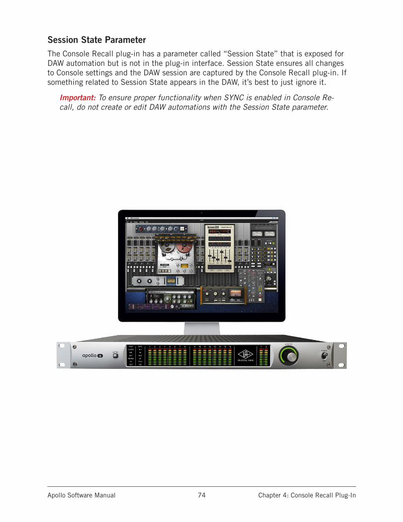
Apollo Software Manual Chapter 4: Console Recall Plug-In 74
Session State ParameterThe Console Recall plug-in has a parameter called “Session State” that is exposed for DAW automation but is not in the plug-in interface. Session State ensures all changes to Console settings and the DAW session are captured by the Console Recall plug-in. If something related to Session State appears in the DAW, it’s best to just ignore it.
Important: To ensure proper functionality when SYNC is enabled in Console Re-call, do not create or edit DAW automations with the Session State parameter.
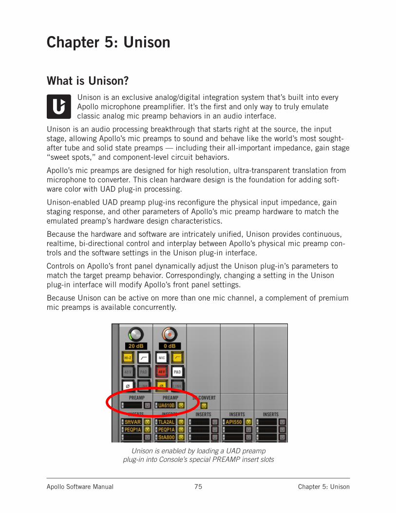
Apollo Software Manual Chapter 5: Unison 75
Chapter 5: Unison
What is Unison?Unison is an exclusive analog/digital integration system that’s built into every Apollo microphone preamplifier. It’s the first and only way to truly emulate classic analog mic preamp behaviors in an audio interface.
Unison is an audio processing breakthrough that starts right at the source, the input stage, allowing Apollo’s mic preamps to sound and behave like the world’s most sought-after tube and solid state preamps — including their all-important impedance, gain stage “sweet spots,” and component-level circuit behaviors.
Apollo’s mic preamps are designed for high resolution, ultra-transparent translation from microphone to converter. This clean hardware design is the foundation for adding soft-ware color with UAD plug-in processing.
Unison-enabled UAD preamp plug-ins reconfigure the physical input impedance, gain staging response, and other parameters of Apollo’s mic preamp hardware to match the emulated preamp’s hardware design characteristics.
Because the hardware and software are intricately unified, Unison provides continuous, realtime, bi-directional control and interplay between Apollo’s physical mic preamp con-trols and the software settings in the Unison plug-in interface.
Controls on Apollo’s front panel dynamically adjust the Unison plug-in’s parameters to match the target preamp behavior. Correspondingly, changing a setting in the Unison plug-in interface will modify Apollo’s front panel settings.
Because Unison can be active on more than one mic channel, a complement of premium mic preamps is available concurrently.
Unison is enabled by loading a UAD preamp plug-in into Console’s special PREAMP insert slots
Apollo Software Manual Chapter 5: Unison 76
Unison FeaturesUnison technology enables these Apollo features, all with Realtime UAD Processing:
• Alternate microphone preamplifier sound – Apollo’s ultra-transparent mic preamps inherit all the unique sonic and input characteristics of the emulated hardware preamp, includ-ing the mic, line, and Hi-Z inputs.
• Realistic tandem control – Unison facilitates seamless interactive control of Unison preamp plug-in settings using Apollo’s digitally-controlled hardware and/or the plug-in interface. All equivalent preamp controls (gain, pad, polarity, etc) are mirrored and bi-directional. The preamp controls respond to adjustments with precisely the same inter-play behavior as the emulated hardware, including gain levels and clipping points.
• Hardware input impedance – All Apollo mic preamps feature variable input impedance in analog hardware that can be physically switched by Unison plug-ins for physical, micro-phone-to-preamp resistive interaction. This impedance switching enables Apollo’s pre-amps to physically match the emulated unit’s input impedance, which can significantly impact the sound of a microphone. Because the electrical loading occurs on input, prior to A/D conversion, the realism is faithful to the original target hardware preamp.
• Tactile gain staging – Apollo’s front panel preamp knob can independently adjust all gain and level parameters available within the Unison plug-in via Gain Stage Mode. The gain stage being adjusted can be remotely switched via Apollo, so multiple gain levels and their associated colorations can be tuned from the hardware knob for precise physical tactile control, all without using the Unison plug-in’s software interface.
Unison Plug-InsUnison-enabled UAD preamplifier plug-ins are uniquely coded for Unison integration. Only UAD preamp plug-ins that are Unison-enabled can be loaded in Console’s PREAMP inserts.
Note: In all descriptive text, “Unison plug-in” is defined as any Unison-enabled UAD preamp plug-in.
Activating UnisonUnison technology is activated when a Unison plug-in is loaded in the special PREAMP insert slots within Apollo’s Console application. Console PREAMP inserts are only available on Apollo’s mic preamp channel inputs.
Note: Unison is unavailable with Apollo 16, which does not feature microphone pream-plifiers.
Unison plug-ins in standard insert slotsUnison plug-ins can be loaded and used in any standard insert slots available on all Console input channels and/or within a DAW via VST/AU/RTAS/AAX (like any UAD plug-in). However, there is no physical or electrical hardware interaction in standard insert slots, so Unison plug-ins operate like other (non-Unison) UAD plug-ins in this scenario.
Important: Unison features are available only when Unison-enabled UAD preamp plug-ins are loaded within Console in the PREAMP insert slots.
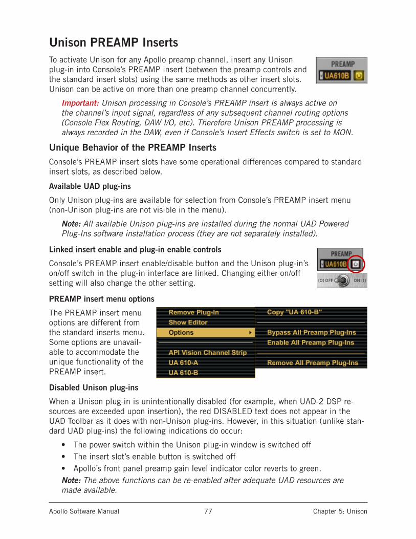
Apollo Software Manual Chapter 5: Unison 77
Unison PREAMP InsertsTo activate Unison for any Apollo preamp channel, insert any Unison plug-in into Console’s PREAMP insert (between the preamp controls and the standard insert slots) using the same methods as other insert slots. Unison can be active on more than one preamp channel concurrently.
Important: Unison processing in Console’s PREAMP insert is always active on the channel’s input signal, regardless of any subsequent channel routing options (Console Flex Routing, DAW I/O, etc). Therefore Unison PREAMP processing is always recorded in the DAW, even if Console’s Insert Effects switch is set to MON.
Unique Behavior of the PREAMP InsertsConsole’s PREAMP insert slots have some operational differences compared to standard insert slots, as described below.
Available UAD plug-ins
Only Unison plug-ins are available for selection from Console’s PREAMP insert menu (non-Unison plug-ins are not visible in the menu).
Note: All available Unison plug-ins are installed during the normal UAD Powered Plug-Ins software installation process (they are not separately installed).
Linked insert enable and plug-in enable controls
Console’s PREAMP insert enable/disable button and the Unison plug-in’s on/off switch in the plug-in interface are linked. Changing either on/off setting will also change the other setting.
PREAMP insert menu options
The PREAMP insert menu options are different from the standard inserts menu. Some options are unavail-able to accommodate the unique functionality of the PREAMP insert.
Disabled Unison plug-ins
When a Unison plug-in is unintentionally disabled (for example, when UAD-2 DSP re-sources are exceeded upon insertion), the red DISABLED text does not appear in the UAD Toolbar as it does with non-Unison plug-ins. However, in this situation (unlike stan-dard UAD plug-ins) the following indications do occur:
• The power switch within the Unison plug-in window is switched off• The insert slot’s enable button is switched off• Apollo’s front panel preamp gain level indicator color reverts to green.Note: The above functions can be re-enabled after adequate UAD resources are made available.
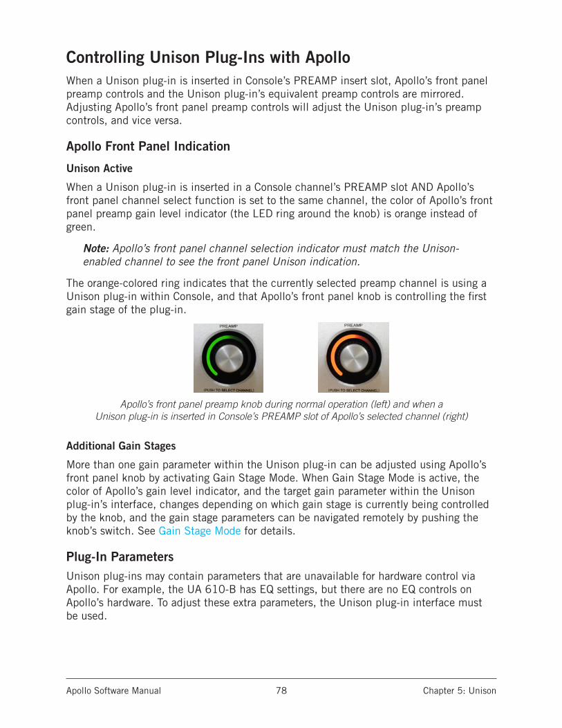
Apollo Software Manual Chapter 5: Unison 78
Controlling Unison Plug-Ins with ApolloWhen a Unison plug-in is inserted in Console’s PREAMP insert slot, Apollo’s front panel preamp controls and the Unison plug-in’s equivalent preamp controls are mirrored. Adjusting Apollo’s front panel preamp controls will adjust the Unison plug-in’s preamp controls, and vice versa.
Apollo Front Panel Indication
Unison Active
When a Unison plug-in is inserted in a Console channel’s PREAMP slot AND Apollo’s front panel channel select function is set to the same channel, the color of Apollo’s front panel preamp gain level indicator (the LED ring around the knob) is orange instead of green.
Note: Apollo’s front panel channel selection indicator must match the Unison-enabled channel to see the front panel Unison indication.
The orange-colored ring indicates that the currently selected preamp channel is using a Unison plug-in within Console, and that Apollo’s front panel knob is controlling the first gain stage of the plug-in.
Apollo’s front panel preamp knob during normal operation (left) and when a Unison plug-in is inserted in Console’s PREAMP slot of Apollo’s selected channel (right)
Additional Gain Stages
More than one gain parameter within the Unison plug-in can be adjusted using Apollo’s front panel knob by activating Gain Stage Mode. When Gain Stage Mode is active, the color of Apollo’s gain level indicator, and the target gain parameter within the Unison plug-in’s interface, changes depending on which gain stage is currently being controlled by the knob, and the gain stage parameters can be navigated remotely by pushing the knob’s switch. See Gain Stage Mode for details.
Plug-In ParametersUnison plug-ins may contain parameters that are unavailable for hardware control via Apollo. For example, the UA 610-B has EQ settings, but there are no EQ controls on Apollo’s hardware. To adjust these extra parameters, the Unison plug-in interface must be used.

Apollo Software Manual Chapter 5: Unison 79
Console Indications
Gain Level Indicator
The color of Console’s preamp gain level indicator (the colored ring around the gain knob), and the channel selection dot on the gain knob, is orange instead of green when Unison is ac-tive in the channel.
If the Unison plug-in is inactive (either via the PREAMP insert disable button or the power switch in the plug-in interface), the color reverts to green.
Note: Console’s preamp gain control only adjusts the first gain stage of any Unison plug-in, even when Apollo is in Gain Stage Mode.
Gain Level Display
The preamp gain level display (the gain value readout under the knob) always shows the current gain value of the first gain stage parameter within the Unison plug-in. Additionally, the display is adapted to the parameter value and range of the first gain stage within the plug-in.
For example, when the UA 610-A Tube Preamp plug-in is in the PREAMP insert, this field displays either “Hi” or “Low” because these are the only two values available in the first gain stage of this plug-in.
Note: This display shows “---” if the Apollo hardware is not detected when a Uni-son plug-in is in the PREAMP insert and the insert is not disabled.
Front Panel Channel Selection
Level Knob Switch
In addition to the rotary control, Apollo’s front panel preamp level knob has a switch function when the knob is pressed. The function of this switch varies depending on the active mode (either Channel Select Mode or Gain Stage Mode), as described below.
Channel Select Mode (standard operation)
Channel selection determines which input channel can being adjusted with Apollo’s front panel preamp controls. This is the standard behavior when a channel is not in Unison mode (front panel channel selection is not related to Unison functionality).
The method used for front panel channel selection depends on the specific Apollo hard-ware model (Apollo or Apollo Twin). The method for each model is described briefly below, in order to differentiate the standard behavior from the Unison behavior.
Note: Standard channel selection is also explained in the hardware manual for each Apollo model (the channel selection methods are used without Unison).
Apollo Software Manual Chapter 5: Unison 80
Apollo onlyPressing the Preamp knob cycles through Apollo’s selected preamp channel (1, 2, 3, 4, repeat). A channel is selected for adjustment when its channel select indicator LED (located above the channel 1, 2, 3, 4 input meters) is lit. If stereo linking is active, the stereo pair(s) LEDs are lit.
Apollo Twin onlyEither of these methods can be used for channel selection with Apollo Twin:
• Level Knob – After the Preamp button has been pressed at least once to switch the unit to Input mode, pressing the Level knob alternates the currently selected input channel (CH1 or CH2).
• Preamp Button – After the Preamp button has been pressed at least once to switch the unit to Input mode, pressing the Preamp button alternates the cur-rently selected input channel (CH1 or CH2).
An Apollo Twin channel is selected for adjustment when its channel selection indicator LED (CH1 or CH2, above the input meters) is lit. If stereo linking is active, both indica-tors LEDs (CH1 and CH2) are lit.
Gain Stage Select (Unison operation only)
When the currently selected Apollo channel is in Gain Stage Mode, pushing the level knob changes the Unison plug-in’s gain parameter that is being controlled.
The color of Apollo’s front panel preamp gain level indicator (the LED ring around the knob) changes to reflect the gain stage being controlled, and the gain stage is also in-dicated by the matching color of the indicator dot within the Unison plug-in’s interface. For complete details, see Gain Stage Mode.

Apollo Software Manual Chapter 5: Unison 81
Gain Stage ModeUnison plug-ins have either two or three gain parameters. By activating Gain Stage Mode, each of these plug-in gain stages can be independently adjusted using Apollo’s front panel gain knob.
Note: Gain Stage Mode can only be active on one preamp channel at a time.
Initially, when Unison is activated (before entering Gain Stage Mode), Apollo’s gain knob controls the first gain parameter within the Unison plug-in. However, when Gain Stage Mode is active, pressing Apollo’s front panel preamp knob cycles through the available gain parameters in the plug-in.
Activating Gain Stage Mode
To enable Apollo’s Gain Stage Mode when using a Unison plug-in:1. In Console, confirm a Unison plug-in is inserted into the PREAMP slot of the
Apollo preamp channel to be controlled. 2. On Apollo’s front panel, select the preamp channel to be controlled using the
standard method for your hardware model (for methods, see page 79).3. Press AND HOLD Apollo’s front panel preamp level knob for at least two seconds.
The state of Gain Stage Mode is indicated on Apollo and in the Unison plug-in, as de-tailed below.
Gain Stage Mode – Apollo Panel Indication
Apollo’s panel channel selection indicator LED flashes when Gain Stage Mode is active for the currently selected preamp channel. The indication varies with the specific Apollo model:
ApolloThe channel selection number LED above its input meter flashes when Gain Stage Mode is active, as shown at right.
Apollo TwinThe channel selection number LED (CH1 or CH2) above the input meters flashes when Gain Stage Mode is active, as shown at right.
Gain Stage Mode – Unison Plug-In Indication
A colored dot appears within the Unison plug-in interface on the target parameter being controlled, as shown at left.
See Gain Stage Colors for related information.
INTCLOCKMIC
+48
Ø LINK
1 2 1 23 4 5 6 7 8
PAD
LINE
EXTCLOCK
UADLINK
PAD
MIC/LINE
+48V
Ø LINK
CLIP
0
-6-3
-9-12-15-18-21-27
CLIP
0
-6-3
-9-12-15-18-21-27
Apollo TwinFlashing Channel Selection
ApolloFlashing Channel Selection
2 3 41
INTCLOCKMIC
+48
Ø LINK
1 2 1 23 4 5 6 7 8
PAD
LINE
EXTCLOCK
UADLINK
PAD
MIC/LINE
+48V
Ø LINK
CLIP
0
-6-3
-9-12-15-18-21-27
CLIP
0
-6-3
-9-12-15-18-21-27
Apollo TwinFlashing Channel Selection
ApolloFlashing Channel Selection
2 3 41
Apollo Software Manual Chapter 5: Unison 82
Deactivating Gain Stage Mode
Gain Stage Mode can be deactivated with any of these methods:• Press and hold Apollo’s front panel gain level knob for at least two seconds
(Apollo Twin must be in Input mode by pressing the Preamp button at least once)• Disable the Unison plug-in via Console’s PREAMP insert enable/disable button• Disable the Unison plug-in via the on/off parameter within the plug-in interface• Remove the Unison plug-in from Console’s PREAMP insert• (Apollo Twin only) Change the selected channel by pressing the PREAMP button
When Gain Stage Mode is deactivated, the following changes occur:1. The gain stage select function (pushing the gain level knob) reverts to the channel
select function2. The channel selection indicator on Apollo’s front panel stops flashing3. If a gain stage other than the first gain stage was being controlled, Apollo’s gain
level knob reverts to control of the first gain stage of the Unison plug-in, and the level indicator color reverts to orange.
Controlling Individual Gain Stages
Selecting Gain Parameters For Control
When the currently selected Unison plug-in channel is in Gain Stage Mode (when its channel selection indicator is flashing), push Apollo’s gain level knob to cycle through the available gain parameters within the Unison plug-in.
Note: Unlike Apollo’s front panel knob, Console’s preamp gain control only adjusts the first gain stage of any Unison plug-in when Apollo is in Gain Stage Mode. To adjust other gain stages from within Console, use Apollo’s gain knob or the Unison plug-in interface.
Gain Stage Colors
The gain stage being controlled is indicated by unique, matching indicator colors on Apollo’s front panel and within the Unison plug-in’s interface.
The color of the gain level indicator on Apollo’s front panel (the LED ring around the knob) changes with each gain stage, and the matching color dot within the Unison plug-in’s interface moves to the target gain parameter being controlled.
The gain stages available for control, and their associated colors, are:
• Orange – Gain stage one; the Gain parameter• Amber – Gain stage two; the Level parameter• Green – Gain stage three, the clean (non-modeled) output control

Apollo Software Manual Chapter 5: Unison 83
Matching Gain Stage IndicatorsIn Gain Stage Mode, Apollo’s preamp level indicator (the LED ring around the knob) matches the colored dot on the target gain parameter in the Unison plug-in’s interface, as shown below. The hardware and software controls are mirrored and the gain stage can be adjusted using either control.
The color of Apollo’s preamp gain level indicator changes to reflect the gain stage being controlled
The matching color dot on the parameter in the Unison plug-in interface indicates which gain stage is being controlled by Apollo’s front panel preamp knob
Available Gain Stages
Unison plug-ins have up to three gain stage parameters. With Unison plug-ins that con-tain two gain parameters, only the available gain parameters are cycled and controlled in Gain Stage Mode.
Note: For details about the unique gain stage parameters available within indi-vidual Unison plug-in titles, refer to the UAD Plug-Ins Manual.
Apollo Software Manual Chapter 5: Unison 84
Unison Load/Save BehaviorsCaution: Apollo hardware preamp settings may change when Console sessions are loaded.
Loading Unison Plug-In SettingsWhen Unison plug-in settings are loaded in Console, the effect upon the currently active Unison plug-in settings varies depending on how the settings are loaded. Its important to understand the distinction, because critical preamp settings can be affected.
Note: When Unison plug-ins are used in Console’s standard inserts and/or within a DAW, this section does not apply. Settings load behavior outside of the PREAMP insert is like all other (non-Unison) UAD plug-ins.
There are two ways Unison (and non-Unison) plug-in settings can be loaded in Console:
• Plug-In Presets – UAD Presets are loaded whenever a UAD plug-in is inserted (the default preset). Presets can be loaded from disk files via the UAD Toolbar. Preset files are used to save & load all settings of individual plug-in titles.
• Console Sessions – Console sessions are loaded from disk via the Console Recall menu, the Console Recall plug-in in a DAW, or by double-clicking Console files on disk. Console sessions are complete Apollo configurations, containing all hardware and plug-in settings (i.e., Console presets).
Loading Presets: Hardware settings are inherited
When a Unison plug-in is loaded in the PREAMP insert and a preset is loaded into the plug-in, the plug-in inherits the current equivalent hardware settings of the Apollo pre-amp, if those settings are available in the plug-in.
In simpler terms, Apollo’s preamp settings always override a Unison plug-in’s settings when a preset is loaded or the plug-in is inserted. This is done to prevent the plug-in’s settings from switching the hardware to values that could cause extreme level changes and/or other unwanted circuit changes such as +48V phantom power.
For example, if the PAD is ON in the Apollo preamp, when the Unison preset is loaded, the pad setting in the plug-in is enabled to prevent unexpected level increases.
Loading Sessions: Hardware settings are overridden
When a Console session is loaded (via Console Recall menu, DAW sessions containing the Console Recall plug-in, or double-clicking Console files on disk), ALL Console set-tings are overridden (changed) by the saved session, INCLUDING ALL APOLLO HARD-WARE PREAMP SETTINGS.
In simpler terms, Console sessions always override Apollo’s preamp settings, even if po-tentially harmful preamp settings are contained in the session file. This is done because the very concept of Console session recall is to reproduce all settings in the session.
For example, if the PAD is OFF in the Apollo preamp, when the Console session is load-ed, the pad setting in the plug-in is disabled and sensitive equipment could be affected, such as speakers (level increases) and/or ribbon mics (phantom power).
Apollo Software Manual Chapter 5: Unison 85
Unison Operation NotesThe operating notes in this section only apply to Unison functionality (when Unison plug-ins are inserted in Console’s PREAMP slots).
The notes do NOT apply to Unison plug-ins that are used in Console’s standard insert slots, nor via VST/AU/RTAS/AAX within a DAW, even when a Unison plug-in title is used. In this scenario, Unison plug-ins function the same as all standard (non-Unison) UAD plug-in titles and there is no physical or electrical hardware interaction.
Important: Unison functionality is available only when Unison-enabled UAD pre-amp plug-ins are loaded within Console in the PREAMP insert slots.
• PREAMP insert processing is always recorded in the DAW (regardless of the cur-rent Insert Effects setting) because Unison plug-ins process the physical inputs.
• A microphone, line input, or Hi-Z instrument source must be attached to the Apollo input channel for Unison plug-in processing in the PREAMP insert to be audible.
• Apollo’s hardware preamp controls remain active even if the Unison plug-in is disabled.
• Because Apollo’s front panel preamp controls are always current and inherited by the Unison plug-in, changes made to a Unison plug-in when the plug-in is by-passed are not retained when the plug-in is reactivated.
• A Unison plug-in’s modeled behaviors and parameter ranges are used by the hard-ware controls whenever possible, even if the attribute is different than Apollo’s stock preamps. For example, if the Unison plug-in has a 15 dB pad, then Apollo’s front panel PAD button value will use the Unison plug-in’s 15 dB value instead of Apollo’s stock 20 dB value.
• Default gain levels when a Unison plug-in is inserted can vary from Apollo’s de-fault (non-Unison) preamp levels, and also between various Unison plug-in titles. This is a by-product of accurate preamp modeling. Because hardware preamp designs from each manufacturer vary, they all have different total gain amounts, control ranges, and control response curves, whether Mic, Line, or Hi-Z.
• If a Unison plug-in does not contain settings that are available on Apollo (pad, low cut filter, etc), the Apollo settings are not changed when the Unison plug-in set-tings are loaded, and the Apollo settings are still available for control via Apollo’s front panel and/or Console channel.
• When a Unison plug-in is removed from the PREAMP insert, Apollo’s mic input impedance reverts to its default value of 5.4K Ohms.
• When the original hardware preamp being emulated by the Unison plug-in has a Hi-Z (instrument) input and associated Hi-Z input switch, this switch is unavail-able in the Unison plug-in interface. Instead, the Unison plug-in’s Hi-Z input is automatically selected when a mono (tip-sleeve) plug is inserted into the Unison channel’s front panel Hi-Z input jack.
(Continued)
Apollo Software Manual Chapter 5: Unison 86
• If Apollo is disconnected from the host computer (standalone mode), the Unison plug-in can no longer be controlled from Apollo’s front panel. However, the signal continues to be processed by the Unison plug-in, using the values that were active when the connection was lost. Note that if Gain Stage Mode is active when the host connection is lost, the gain stage can apparently be switched from the front panel. However, the actual gain stage being controlled does not change.

Apollo Software Manual Chapter 6: Working With Apollo 87
Chapter 6: Working With Apollo
Apollo Setups OverviewApollo is a powerful and flexible audio interface that can be used in many ways. This chapter explains how to apply Apollo in various digital audio environments.
Although the exact techniques for configuring and using Apollo will vary according to needs, its application will generally fall within one of the main categories below. Each application is detailed later in this chapter.
Audio interface without DSPApollo functions like other non-DSP audio interfaces when it is used without the Console application, the Console Recall plug-in, or UAD Powered Plug-Ins. See “Using Apollo as an Audio Interface” on page 90 for details.
Digital mixer with ConsoleApollo and Console can be used without a DAW or any other audio software, providing access to all Apollo features, its DSP mixing functionality, and Realtime UAD Processing. See “Using Apollo with Console (without a DAW)” on page 92 for details.
Standalone use without computer Apollo can be used as a digital mixer (with limited functionality) without Console or any connection to a host computer. See “Using Apollo Without A Computer” on page 93 for details.
With a DAW (without Console)When Apollo is used with a DAW but without the Console application (or Console Recall plug-in), the DAW controls all signal I/O routing, software monitoring, and UAD-2 DSP-accelerated UAD Powered Plug-Ins processing. See “Using Apollo with a DAW (without Console)” on page 94 for details.
With Console and a DAWConsole is used concurrently with a DAW when low-latency monitoring and/or recording of Apollo’s inputs with (or without) Realtime UAD processing is desired. This workflow completely eliminates the I/O buffering latencies associated with software monitoring. Console’s Virtual I/O feature can also be used with the DAW to route virtual software instruments, or any other DAW outputs, into Console for Realtime UAD Processing. See “Using Apollo Concurrently with a DAW and Console” on page 96 for details.
UAD Powered Plug-Ins: Console versus DAWThere are some fundamental differences when UAD Powered Plug-Ins within Console or within a DAW. See “About UAD Powered Plug-Ins Processing” on page 88 for details.
Apollo Software Manual Chapter 6: Working With Apollo 88
About UAD Powered Plug-Ins Processing
Two Distinct Methods with ApolloApollo features two distinct methods for using UAD Powered Plug-Ins: The “Console processing method” for low-latency monitoring and tracking with Realtime UAD Process-ing via the Console application, and the “DAW processing method” for DSP-accelerated UAD-2 processing via VST, RTAS, AAX, and Audio Units plug-ins in DAW applications.
These two methods are not a switched mode, but instead simply depend on which ap-plication (Console or DAW) uses the UAD plug-ins. Both methods can be used simultane-ously for extremely powerful and flexible signal monitoring, routing, and processing.
Console Processing Method
UAD Powered Plug-Ins run in realtime only when used within Console. Using Realtime UAD Processing in Console is optimum for artists and engineers that need to monitor and capture performances without DAW I/O buffering latency and its associated hindrances.
The special Realtime UAD Processing functionality is achieved via Apollo’s unique ultra-low latency DSP+FPGA+Console design. Although every audio interface has undetectable latency that is inherent to the A/D–D/A process, routing Apollo’s input signals through UAD Powered Plug-Ins within Console does not add to this inherent latency.
Up to four UAD plug-in instances can be inserted serially (“stacked” or “chained”) on each of Console’s analog/digital inputs and/or auxiliary buses simultaneously, without adding to the inherent I/O latency.
Note: Upsampled UAD plug-ins add latency when used within Console or a DAW. See “Upsampled UAD Plug-Ins” on page 116 for more information.
Console inputs with Realtime UAD processing can be routed into the DAW via Apollo’s device drivers, and optionally recorded as either processed (wet) or unprocessed (dry) audio using the Insert Effects function in Console.
Important: UAD plug-ins used within Console for Realtime UAD Processing must run on the DSP within Apollo. If other UAD-2 devices are active in the same sys-tem, DSP on those devices cannot be used for Realtime UAD Processing.
Apollo Software Manual Chapter 6: Working With Apollo 89
DAW Processing Method
When UAD Powered Plug-Ins are used within compatible VST, RTAS, AAX 64, or Audio Units host DAW applications, I/O buffering is used for plug-in processing because the data must be shuttled back and forth between the DAW and Apollo. In this scenario, the UAD-2 DSP inside Apollo behaves exactly like other UAD-2 devices such as UAD-2 Sat-ellite and UAD-2 PCIe cards for UAD plug-in processing.
Hardware I/O buffering with a DAW adds latency that is compensated by the host DAW’s automatic delay compensation during mixing (i.e., all tracks remain time-aligned). How-ever, at larger buffer sizes this latency makes software monitoring via the DAW mixer while tracking with UAD Powered Plug-Ins less practical. Using Apollo Concurrently with a DAW and Console eliminates this latency during tracking because software monitoring is not used — the DSP mixer inside Apollo is used for “hardware” monitoring instead.
Note: See “Chapter 8: Latency & Apollo” on page 111 for detailed information about latency.
Latency is not an issue during mixdown in a DAW; realtime processing is not necessary because the performances are already captured. The benefits of using Apollo’s integrated DSP acceleration during mixing include the off-loading of plug-in processing from the host computer’s CPU and the sonic rewards of UAD Powered Plug-Ins, which run exclu-sively on UAD-2 and Apollo platforms.
Concurrent use of UAD Plug-Ins in Console and a DAW
UAD Powered Plug-Ins can be used within Console and a DAW simultaneously. In this scenario, Apollo’s DSP resources are shared between the two applications. Realtime UAD Processing is available via Console, and I/O buffered (non-realtime) UAD processing is available via VST, RTAS, AAX 64, or Audio Units plug-ins in the DAW. See page 96 for complete details.
Note: Apollo, like other UAD devices, can only load UAD Powered Plug-Ins which are specifically designed to run on UAD DSP accelerators. Host-based “native” plug-ins cannot run on the UAD DSP.
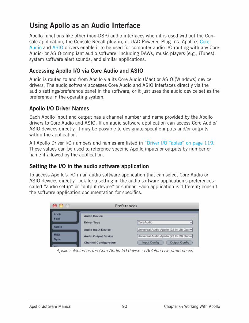
Apollo Software Manual Chapter 6: Working With Apollo 90
Using Apollo as an Audio InterfaceApollo functions like other (non-DSP) audio interfaces when it is used without the Con-sole application, the Console Recall plug-in, or UAD Powered Plug-Ins. Apollo’s Core Audio and ASIO drivers enable it to be used for computer audio I/O routing with any Core Audio- or ASIO-compliant audio software, including DAWs, music players (e.g., iTunes), system software alert sounds, and similar applications.
Accessing Apollo I/O via Core Audio and ASIOAudio is routed to and from Apollo via its Core Audio (Mac) or ASIO (Windows) device drivers. The audio software accesses Core Audio and ASIO interfaces directly via the audio settings/preference panel in the software, or it just uses the audio device set as the preference in the operating system.
Apollo I/O Driver NamesEach Apollo input and output has a channel number and name provided by the Apollo drivers to Core Audio and ASIO. If an audio software application can access Core Audio/ASIO devices directly, it may be possible to designate specific inputs and/or outputs within the application.
All Apollo Driver I/O numbers and names are listed in “Driver I/O Tables” on page 119. These values can be used to reference specific Apollo inputs or outputs by number or name if allowed by the application.
Setting the I/O in the audio software applicationTo access Apollo’s I/O in an audio software application that can select Core Audio or ASIO devices directly, look for a setting in the audio software application’s preferences called “audio setup” or “output device” or similar. Each application is different; consult the software application documentation for specifics.
Apollo selected as the Core Audio I/O device in Ableton Live preferences
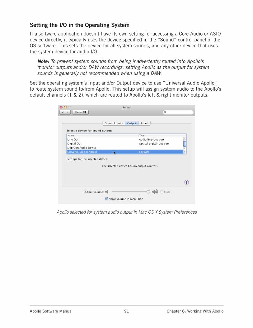
Apollo Software Manual Chapter 6: Working With Apollo 91
Setting the I/O in the Operating SystemIf a software application doesn’t have its own setting for accessing a Core Audio or ASIO device directly, it typically uses the device specified in the “Sound” control panel of the OS software. This sets the device for all system sounds, and any other device that uses the system device for audio I/O.
Note: To prevent system sounds from being inadvertently routed into Apollo’s monitor outputs and/or DAW recordings, setting Apollo as the output for system sounds is generally not recommended when using a DAW.
Set the operating system’s Input and/or Output device to use “Universal Audio Apollo” to route system sound to/from Apollo. This setup will assign system audio to the Apollo’s default channels (1 & 2), which are routed to Apollo’s left & right monitor outputs.
Apollo selected for system audio output in Mac OS X System Preferences
Apollo Software Manual Chapter 6: Working With Apollo 92
Using Apollo with Console (without a DAW)Apollo and Console can be used without a DAW or any other audio software. Using Con-sole without a DAW provides access to all Apollo functionality and simplifies the use of Apollo’s digital mixing, monitoring, and Realtime UAD processing features when a DAW’s recording and playback features are not needed.
Apollo has an internal DSP mixer for realtime mixing and monitoring of Apollo inputs, with optional Realtime UAD Processing using UAD Powered Plug-Ins. The software in-terface for this functionality is the Console application, but the actual mixing and signal processing occurs inside Apollo.
Using Console by itselfTo use the Console Mixer by itself for input monitoring and Realtime UAD Processing, there aren’t any special considerations; just launch Console and start using it. Full expla-nations of all Console features and functionality are in “Chapter 3: Console Application” beginning on page 19.
Using Console with other audio applicationsSystem Audio
When the OS is set to use Apollo for computer system audio (page 91), the computer system audio is routed to Console’s monitor outputs and mixed with Apollo inputs (if any).
Apollo’s input levels can be adjusted with Console’s input channel faders, while the com-puter system’s audio level at the monitor outputs is determined by the volume settings of the audio software using the system outputs. The computer system volume level is not adjusted in the Console Mixer.
With a DAW
DAWs have their own audio mixer. Understanding the interactions between Console and the DAW will help to ensure an optimized workflow in this scenario. See “Using Apollo Concurrently with a DAW and Console” on page 96 for details.

Apollo Software Manual Chapter 6: Working With Apollo 93
Using Apollo Without A Computer
Standalone UseAlthough the Console application and/or a DAW are required to unleash the full potential of Apollo, the unit can be used as a standalone digital mixer with limited functionality without any FireWire or Thunderbolt connection to a host computer.
Console settings that are retained on power cycle
All currently active I/O assignments, signal routings, and monitor settings are saved to internal firmware before Apollo is powered down, and recalled when power is re-applied. Therefore these last-used settings are available even when a host computer is not used.
UAD plug-ins are not retained on power cycle
UAD Powered Plug-In instantiations are not retained after powering down then powering up again, because the plug-in files must be loaded from the host computer.
Standalone use with UAD plug-insIf UAD plug-ins are active when Apollo’s connection to the host computer is lost (ei-ther by disconnecting the cable or shutting down the computer), Console’s current UAD plug-in configurations remain active for Realtime UAD Processing until Apollo is powered down.
Disconnecting
Upon disconnection from the host computer, the following changes occur:
• Auxiliary buses are unmuted• Solo is deactivated on all channels• If multi-unit cascading, the clock source switches to Word Clock
Operation
After disconnecting, the following behavior applies:
• The LINK switch on Apollo’s front panel cannot be used to link or unlink stereo channels. This point only applies if the host connection was lost; the switch does operate when Apollo is powered on before connecting to a host computer.
• If channels 1 & 2 are stereo linked and an instrument is plugged into one of the Hi-Z inputs, the stereo link is unlinked, and UAD plug-in processing is bypassed on both channels. The stereo link, and UAD processing, returns when the Hi-Z input is removed.
Apollo Software Manual Chapter 6: Working With Apollo 94
Using Apollo with a DAW (without Console)When used with a DAW but without the Console application (or Console Recall plug-in), the DAW controls all signal I/O routing, software monitoring, and DSP-accelerated UAD Powered Plug-Ins processing.
Note: Apollo, like other UAD devices, can only load UAD Powered Plug-Ins which are specifically designed to run on UAD DSP accelerators. Host-based “native” plug-ins cannot run on the UAD DSP.
Using a DAW without Console is a typical workflow during mixdown, where low-latency monitoring is not required and buffering latency is not an issue because the tracks are already recorded. When recording new tracks, the DAW+Console workflow (following sec-tion) is recommended.
In this scenario, Apollo functions as two “separate” devices: an audio interface, and a UAD-2 DSP accelerator:
1. Audio Interface – The DAW accesses and routes Apollo’s audio interface I/O via the Core Audio or ASIO device drivers. Audio I/O latency is determined by the I/O Buffer Size setting.
2. UAD-2 DSP Accelerator – The DAW controls Apollo’s internal UAD-2 DSP via UAD plug-ins in VST, RTAS, AAX, or Audio Units format that are loaded within the DAW. Buffering is used for UAD plug-ins because data from the DAW must be shuttled over FireWire or Thunderbolt to/from Apollo’s DSP.
Accessing Apollo’s I/O in a DAWSpecifying the audio interface device
To access Apollo’s I/O within a DAW, the DAW’s audio engine must be configured to use Apollo as the audio interface device. Specific instructions vary by DAW; consult the DAW documentation for specifics. The I/O Buffer Size setting, which determines the overall DAW I/O latency, is usually set in the same window.
See “Setting the I/O in the audio software application” on page 90 for an example.
I/O Complement
The specific inputs and outputs available, and their names, vary by Apollo model. For complete lists, see “Driver I/O Tables” on page 119.

Apollo Software Manual Chapter 6: Working With Apollo 95
Selecting Apollo’s Inputs and Outputs
When the DAW is configured to use Apollo as the audio interface device, the DAW’s audio input and output channels can be routed to/from Apollo’s I/O via the device drivers.
Apollo’s inputs (left) and outputs (right) as they appear when configuring stereo I/O in Logic Pro
Default Outputs
The main stereo outputs of a DAW usually output to channels 1 & 2 by default. There-fore, since channels 1 & 2 correspond to Apollo’s monitor outputs, the DAW’s main out-puts are sent to Apollo’s monitor outputs by default. The channels used for output can usually be changed in the DAW.
Apollo I/O Driver Names
Each Apollo input and output has a channel number and name provided by the Apollo drivers. The DAW uses these numbers or names to designate the specific inputs and/or outputs within the DAW.
Numbers vs. Names
Apollo’s drivers describe all I/O channels by name and number, but what is actually displayed depends on each particular DAW. Names are not displayed by all DAWs (e.g., Ableton Live), or the driver name display mode may need to be changed in the DAW (e.g., Apple Logic Pro).
All Apollo driver I/O numbers and names are listed in “Driver I/O Tables” on page 119. These values can be used to reference specific Apollo inputs or outputs by name when selecting I/O in an application that does not display the driver names.
Apollo Software Manual Chapter 6: Working With Apollo 96
Using Apollo Concurrently with a DAW and ConsoleConsole is used concurrently with a DAW when low-latency monitoring and/or recording of Apollo’s inputs or mix buses with (or without) Realtime UAD Processing is desired. This workflow completely eliminates the I/O buffering latencies associated with software monitoring.
In this scenario, Console is used to control all input monitoring and Realtime UAD Pro-cessing when recording, and the DAW’s software monitoring feature should be disabled.
Software Monitoring versus Hardware MonitoringSoftware monitoring (listening to live inputs via the DAW mixer) has discernible latency due to audio interface I/O buffering. Hardware monitoring via an audio interface’s in-ternal DSP mixer (e.g., Apollo’s Console application) does not have discernible latency, because the live audio is internally routed directly from the inputs to the outputs without DAW I/O buffering (see “Latency Basics” on page 115 for detailed explanations).
Monitoring with ConsoleThe primary function of Console is monitoring of Apollo’s inputs during live performance, with (or without) Realtime UAD Processing. When used with a DAW, Console is used as a monitor mixer that functions separately from the DAW’s software monitoring mixer.
Disable Software Monitoring in the DAW when using Console
When Console is used for live input monitoring with a DAW, the DAW’s software moni-toring feature should be disabled. If it isn’t, phasing and/or doubling of the monitored signal(s) will occur, because the input signal is being heard twice – first from the low-latency DSP mix (Console) and shortly thereafter from the higher latency software mix (DAW).
Important: To eliminate doubled signals, disable software monitoring in the DAW when Console is used to monitor Apollo’s inputs. Refer to the DAW documentation for specific instructions on how to defeat software monitoring in the DAW.
Routing and Recording Console Inputs and Mix BusesRecording Apollo inputs
This functionality is covered in “Accessing Apollo’s I/O in a DAW” on page 94.
Recording Console mix buses
Console’s monitor and send bus outputs can be routed into the DAW for recording Con-sole’s active mixes. See “Virtual I/O” on page 98 for details.
Recording Realtime UAD Processing
When monitoring Apollo’s inputs with Realtime UAD Processing, those inputs can be recorded with processing (wet) or without processing (dry). This function is accomplished with the Insert Effects switch. See “Insert Effects” on page 47 for details.
Apollo Software Manual Chapter 6: Working With Apollo 97
Console with the Console Recall Plug-InThe Console Recall plug-in offers additional convenience when using Apollo and/or the Console application in conjunction with a DAW. Its primary function is to store complete Console settings within the DAW project file.
When a DAW project is loaded containing the Console Recall plug-in and the “Synchro-nize” function in the plug-in is enabled, the Console settings stored within the newly-loaded DAW session are sent to Console. See “SYNC” on page 73 for details.
Latency CompensationSome latency is inevitable in complex digital audio environments such as when running a DAW with Console. Fortunately, when these applications are properly configured and operated, latency is not a deterrent because it is negligible during low-latency monitor-ing via Console, and automatically managed for time-alignment of recorded tracks via the DAW’s automatic delay compensation feature.
See “Delay Compensation with Apollo” on page 111 for more information.
Recording multiple inputs simultaneously
Console’s Input Delay Compensation feature should be enabled to maintain phase align-ment when monitoring and/or recording simultaneous multi-channel sources (such as a drum kit or multi-mic’d guitar amp) when Realtime UAD Processing is active in Console and some (or all) of the UAD plug-ins in Console are upsampled. See “Input Delay Com-pensation in Console” on page 111 for complete details.
Latency Basics
For a complete overview of latency in a digital audio system, see “Latency Basics” on page 115.
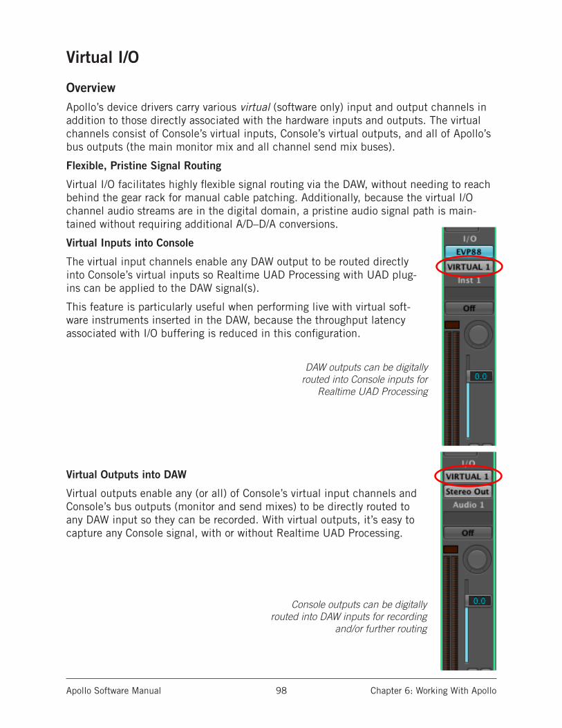
Apollo Software Manual Chapter 6: Working With Apollo 98
Virtual I/O
OverviewApollo’s device drivers carry various virtual (software only) input and output channels in addition to those directly associated with the hardware inputs and outputs. The virtual channels consist of Console’s virtual inputs, Console’s virtual outputs, and all of Apollo’s bus outputs (the main monitor mix and all channel send mix buses).
Flexible, Pristine Signal Routing
Virtual I/O facilitates highly flexible signal routing via the DAW, without needing to reach behind the gear rack for manual cable patching. Additionally, because the virtual I/O channel audio streams are in the digital domain, a pristine audio signal path is main-tained without requiring additional A/D–D/A conversions.
Virtual Inputs into Console
The virtual input channels enable any DAW output to be routed directly into Console’s virtual inputs so Realtime UAD Processing with UAD plug-ins can be applied to the DAW signal(s).
This feature is particularly useful when performing live with virtual soft-ware instruments inserted in the DAW, because the throughput latency associated with I/O buffering is reduced in this configuration.
DAW outputs can be digitally routed into Console inputs for
Realtime UAD Processing
Virtual Outputs into DAW
Virtual outputs enable any (or all) of Console’s virtual input channels and Console’s bus outputs (monitor and send mixes) to be directly routed to any DAW input so they can be recorded. With virtual outputs, it’s easy to capture any Console signal, with or without Realtime UAD Processing.
Console outputs can be digitally routed into DAW inputs for recording
and/or further routing
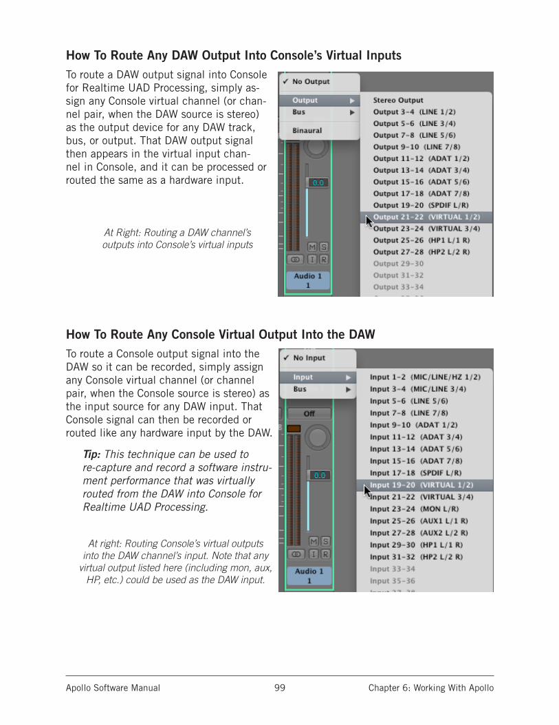
Apollo Software Manual Chapter 6: Working With Apollo 99
How To Route Any DAW Output Into Console’s Virtual InputsTo route a DAW output signal into Console for Realtime UAD Processing, simply as-sign any Console virtual channel (or chan-nel pair, when the DAW source is stereo) as the output device for any DAW track, bus, or output. That DAW output signal then appears in the virtual input chan-nel in Console, and it can be processed or routed the same as a hardware input.
At Right: Routing a DAW channel’s outputs into Console’s virtual inputs
How To Route Any Console Virtual Output Into the DAWTo route a Console output signal into the DAW so it can be recorded, simply assign any Console virtual channel (or channel pair, when the Console source is stereo) as the input source for any DAW input. That Console signal can then be recorded or routed like any hardware input by the DAW.
Tip: This technique can be used to re-capture and record a software instru-ment performance that was virtually routed from the DAW into Console for Realtime UAD Processing.
At right: Routing Console’s virtual outputs into the DAW channel’s input. Note that any
virtual output listed here (including mon, aux, HP, etc.) could be used as the DAW input.

Apollo Software Manual Chapter 6: Working With Apollo 100
PT Mode
PT Mode accommodates Pro Tools software I/O by inserting NULL (empty) values at Apollo inputs 1–2 so line input and output channel numbering within Pro Tools is aligned. The setting also optimizes Apollo’s I/O channels to accommodate the 32 I/O channels available in Pro Tools.
Note: PT Mode is unavailable with Apollo Twin.
How PT Mode changes Apollo’s I/O numbering
Enabling PT Mode
To enable PT Mode, click the PT Mode checkbox in the global interface settings area in the Interface panel within the Con-sole Settings window.
Changes To I/O Complement
Important: Enabling PT Mode changes the driver I/O complement. Quit all audio applications before changing the PT Mode setting.
DAW I/O driver numbering
PT Mode changes Apollo’s driver I/O numbering and names. If a DAW project saved with PT Mode disabled (or saved prior to UAD v7.0.0) is subsequently opened when PT Mode is enabled, the DAW’s channel I/O assignments may need to be adjusted.
The specific Apollo channel numbers and names when PT Mode is active are listed in the PT Mode tables in “Driver I/O Tables” on page 119.
Optimized Apollo channels in Pro Tools
Because Apollo’s I/O channel numbering exceed the 32 channels available in Pro Tools in certain configurations (such as when multi-unit cascading), the available I/O channels are optimized when PT Mode is active.
Note: Channel numbers higher than 32 are unavailable in Pro Tools when PT Mode is active. The specific channels that are unavailable in Pro Tools are dis-played in italics within parentheses in the PT Mode tables in “Driver I/O Tables” on page 119.
Line 1 Line 2 Line 3 (etc.)
Mon L Mon R Line 1 Line 2 (etc.)
InputsPT MODE OFF
Outputs
OffsetI/O
PT MODE ON
Line 1 Line 2 (etc.)NULLNULL
Mon L Mon R Line 1 Line 2 (etc.)
Inputs
Outputs
AlignedI/O

Apollo Software Manual Chapter 6: Working With Apollo 101
Pro Tools Hardware Inserts
To configure the Pro Tools hardware inserts so the insert labels are aligned with Apollo’s I/O, the I/O needs to be offset in the Pro Tools I/O Setup window’s “Insert” tab. This is accomplished by manually dragging each I/O insert pair to the right so they appear as in the screenshot below.
Pro Tools hardware inserts properly configured for Apollo I/O when PT Mode is active
Apollo Software Manual Chapter 7: Multi-Unit Cascading 102
Chapter 7: Multi-Unit Cascading
Multi-Unit OverviewTwo Apollo or two Apollo 16 units can be cascaded together in a multiple-unit configuration (Apollo Twin cannot be used with multi-unit cascading). When two units are connected, both units are controlled within a single Console Mixer window, and the I/O complement of both units are available to the DAW via the device drivers. Operating a multi-unit system is nearly identical to that of a single-unit system for seamless expansion when more I/O is needed.
Note: Combining Apollo with Apollo 16 is an unsupported configuration.
Console IntegrationWhen multi-unit cascading, the number of Console inputs is increased to match the increased hardware inputs. Both units share the same monitor and send buses for integrated mixing con-venience.
Monitor and Expander Units
To facilitate Realtime UAD Processing and the mix bus integration within Console, one device must be designated as the monitor (master) unit and the other as the expander (slave) unit. In driver I/O list ordering, the monitor unit I/O precedes the expander unit I/O.
All Console mix bus outputs (monitor, auxiliary, headphone, cue) are available on the monitor unit only. The designated monitor/expander units can be switched within Console if desired.
Hardware SetupsIn all multi-unit setups, specific hardware wiring connections are required, and only the monitor unit is connected to the host computer system. The expander unit is connected to the monitor unit, not the host computer.
The specific connections differ for Apollo and Apollo 16, and they differ depending on whether FireWire 800 or Thunderbolt is used for the host computer connection. Diagrams for all hard-ware setups are in this chapter starting on page 103.
Note: The inter-unit optical cable is required for mix bus integration and when multi-unit cascading.
ConstraintsDepending on the specific configuration, certain features and/or I/O streams are reduced when multi-unit cascading. See “Constraints” on page 110 for details.
Driver I/O TablesDriver I/O availability and numbering changes when multi-unit cascading and when PT Mode is enabled. For a complete list of all possible I/O states, see “Driver I/O Tables” on page 119.
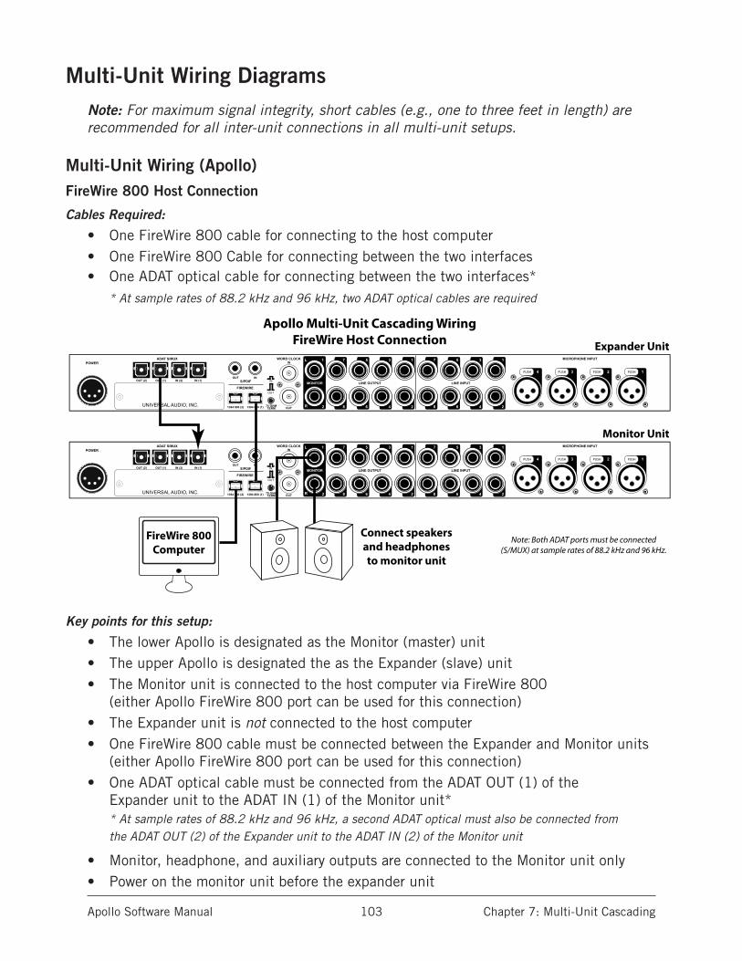
Apollo Software Manual Chapter 7: Multi-Unit Cascading 103
Multi-Unit Wiring DiagramsNote: For maximum signal integrity, short cables (e.g., one to three feet in length) are recommended for all inter-unit connections in all multi-unit setups.
Multi-Unit Wiring (Apollo)FireWire 800 Host Connection
Cables Required:
• One FireWire 800 cable for connecting to the host computer• One FireWire 800 Cable for connecting between the two interfaces• One ADAT optical cable for connecting between the two interfaces*
* At sample rates of 88.2 kHz and 96 kHz, two ADAT optical cables are required
Key points for this setup:
• The lower Apollo is designated as the Monitor (master) unit• The upper Apollo is designated the as the Expander (slave) unit• The Monitor unit is connected to the host computer via FireWire 800
(either Apollo FireWire 800 port can be used for this connection)• The Expander unit is not connected to the host computer• One FireWire 800 cable must be connected between the Expander and Monitor units
(either Apollo FireWire 800 port can be used for this connection)• One ADAT optical cable must be connected from the ADAT OUT (1) of the
Expander unit to the ADAT IN (1) of the Monitor unit** At sample rates of 88.2 kHz and 96 kHz, a second ADAT optical must also be connected from the ADAT OUT (2) of the Expander unit to the ADAT IN (2) of the Monitor unit
• Monitor, headphone, and auxiliary outputs are connected to the Monitor unit only• Power on the monitor unit before the expander unit
LINE INPUT
MICROPHONE INPUT
LINE OUTPUTMONITOR
ADAT S/MUXPOWER
1357
2468
1357
2468
1L
R 2
PUSHPUSH PUSH PUSH 1234
S/PDIF
FIREWIRE
INOUT
1394 800 (2) 1394 800 (1)
WORDCLOCK
WORDCLOCK
INWORD CLOCK
OUT75 OHMTERM
IN
OUT
OUT (1)OUT (2) IN (1)IN (2)
UNIVERSAL AUDIO, INC.
LINE INPUT
MICROPHONE INPUT
LINE OUTPUTMONITOR
ADAT S/MUXPOWER
1357
2468
1357
2468
1L
R 2
PUSHPUSH PUSH PUSH 1234
S/PDIF
FIREWIRE
INOUT
1394 800 (2) 1394 800 (1)
WORDCLOCK
WORDCLOCK
INWORD CLOCK
OUT75 OHMTERM
IN
OUT
OUT (1)OUT (2) IN (1)IN (2)
UNIVERSAL AUDIO, INC.
Expander Unit
Monitor Unit
FireWire 800Computer
Connect speakersand headphonesto monitor unit
Note: Both ADAT ports must be connected(S/MUX) at sample rates of 88.2 kHz and 96 kHz.
Apollo Multi-Unit Cascading WiringFireWire Host Connection
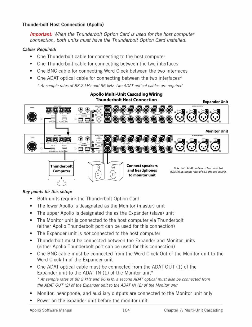
Apollo Software Manual Chapter 7: Multi-Unit Cascading 104
Thunderbolt Host Connection (Apollo)
Important: When the Thunderbolt Option Card is used for the host computer connection, both units must have the Thunderbolt Option Card installed.
Cables Required:
• One Thunderbolt cable for connecting to the host computer• One Thunderbolt cable for connecting between the two interfaces• One BNC cable for connecting Word Clock between the two interfaces• One ADAT optical cable for connecting between the two interfaces*
* At sample rates of 88.2 kHz and 96 kHz, two ADAT optical cables are required
Key points for this setup:
• Both units require the Thunderbolt Option Card• The lower Apollo is designated as the Monitor (master) unit• The upper Apollo is designated the as the Expander (slave) unit• The Monitor unit is connected to the host computer via Thunderbolt
(either Apollo Thunderbolt port can be used for this connection)• The Expander unit is not connected to the host computer• Thunderbolt must be connected between the Expander and Monitor units
(either Apollo Thunderbolt port can be used for this connection)• One BNC cable must be connected from the Word Clock Out of the Monitor unit to the
Word Clock In of the Expander unit• One ADAT optical cable must be connected from the ADAT OUT (1) of the
Expander unit to the ADAT IN (1) of the Monitor unit** At sample rates of 88.2 kHz and 96 kHz, a second ADAT optical must also be connected from the ADAT OUT (2) of the Expander unit to the ADAT IN (2) of the Monitor unit
• Monitor, headphone, and auxiliary outputs are connected to the Monitor unit only• Power on the expander unit before the monitor unit
LINE INPUT
MICROPHONE INPUT
LINE OUTPUTMONITOR
ADAT S/MUXPOWER
1357
2468
1357
2468
1L
R 2
PUSHPUSH PUSH PUSH 1234
S/PDIF
FIREWIRE
INOUT
1394 800 (2) 1394 800 (1)
WORDCLOCK
WORDCLOCK
INWORD CLOCK
OUT75 OHMTERM
IN
OUT
OUT (1)OUT (2) IN (1)IN (2)
UNIVERSAL AUDIO, INC.
PORT 1( ) PORT 2( )
LINE INPUT
MICROPHONE INPUT
LINE OUTPUTMONITOR
ADAT S/MUXPOWER
1357
2468
1357
2468
1L
R 2
PUSHPUSH PUSH PUSH 1234
S/PDIF
FIREWIRE
INOUT
1394 800 (2) 1394 800 (1)
WORDCLOCK
WORDCLOCK
INWORD CLOCK
OUT75 OHMTERM
IN
OUT
OUT (1)OUT (2) IN (1)IN (2)
UNIVERSAL AUDIO, INC.
PORT 1( ) PORT 2( )
Expander Unit
Monitor Unit
ThunderboltComputer
Connect speakersand headphonesto monitor unit
Apollo Multi-Unit Cascading WiringThunderbolt Host Connection
Note: Both ADAT ports must be connected(S/MUX) at sample rates of 88.2 kHz and 96 kHz.
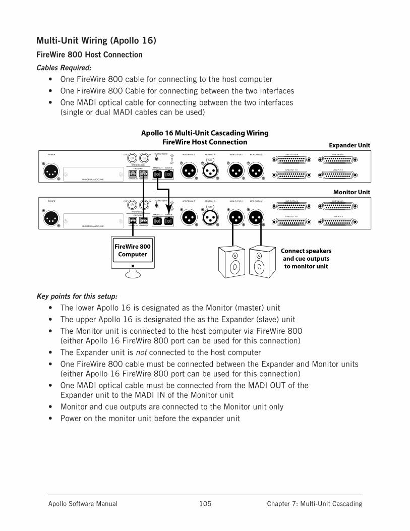
Apollo Software Manual Chapter 7: Multi-Unit Cascading 105
Multi-Unit Wiring (Apollo 16)FireWire 800 Host Connection
Cables Required:
• One FireWire 800 cable for connecting to the host computer• One FireWire 800 Cable for connecting between the two interfaces• One MADI optical cable for connecting between the two interfaces
(single or dual MADI cables can be used)
Key points for this setup:
• The lower Apollo 16 is designated as the Monitor (master) unit• The upper Apollo 16 is designated the as the Expander (slave) unit• The Monitor unit is connected to the host computer via FireWire 800
(either Apollo 16 FireWire 800 port can be used for this connection)• The Expander unit is not connected to the host computer• One FireWire 800 cable must be connected between the Expander and Monitor units
(either Apollo 16 FireWire 800 port can be used for this connection)• One MADI optical cable must be connected from the MADI OUT of the
Expander unit to the MADI IN of the Monitor unit• Monitor and cue outputs are connected to the Monitor unit only• Power on the monitor unit before the expander unit
POWER OUTON
OFF
IN 75 OHM TERM
WORD CLOCK
FIREWIRE
UNIVERSAL AUDIO, INC.
MON OUT (R) 2 MON OUT (L) 1
LINE OUT 1-8 LINE IN 1-8
LINE IN 9-16
MADI OUT MADI IN
AES/EBU OUT AES/EBU IN
PUSH
LINE OUT 9-16
1394 800 (1) 1394 800 (2)
POWER OUTON
OFF
IN 75 OHM TERM
WORD CLOCK
FIREWIRE
UNIVERSAL AUDIO, INC.
MON OUT (R) 2 MON OUT (L) 1
LINE OUT 1-8 LINE IN 1-8
LINE IN 9-16
MADI OUT MADI IN
AES/EBU OUT AES/EBU IN
PUSH
LINE OUT 9-16
1394 800 (1) 1394 800 (2)
Expander Unit
Monitor Unit
FireWire 800Computer Connect speakers
and cue outputsto monitor unit
Apollo 16 Multi-Unit Cascading WiringFireWire Host Connection
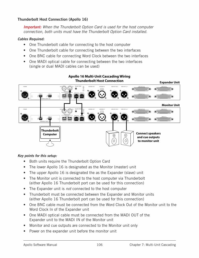
Apollo Software Manual Chapter 7: Multi-Unit Cascading 106
Thunderbolt Host Connection (Apollo 16)
Important: When the Thunderbolt Option Card is used for the host computer connection, both units must have the Thunderbolt Option Card installed.
Cables Required:
• One Thunderbolt cable for connecting to the host computer• One Thunderbolt cable for connecting between the two interfaces• One BNC cable for connecting Word Clock between the two interfaces• One MADI optical cable for connecting between the two interfaces
(single or dual MADI cables can be used)
Key points for this setup:
• Both units require the Thunderbolt Option Card• The lower Apollo 16 is designated as the Monitor (master) unit• The upper Apollo 16 is designated the as the Expander (slave) unit• The Monitor unit is connected to the host computer via Thunderbolt
(either Apollo 16 Thunderbolt port can be used for this connection)• The Expander unit is not connected to the host computer• Thunderbolt must be connected between the Expander and Monitor units
(either Apollo 16 Thunderbolt port can be used for this connection)• One BNC cable must be connected from the Word Clock Out of the Monitor unit to the
Word Clock In of the Expander unit• One MADI optical cable must be connected from the MADI OUT of the
Expander unit to the MADI IN of the Monitor unit• Monitor and cue outputs are connected to the Monitor unit only• Power on the expander unit before the monitor unit
POWER OUTON
OFF
IN 75 OHM TERM
WORD CLOCK
FIREWIRE
UNIVERSAL AUDIO, INC.
PORT 1( ) PORT 2( )
MON OUT (R) 2 MON OUT (L) 1
LINE OUT 1-8 LINE IN 1-8
LINE IN 9-16
MADI OUT MADI IN
AES/EBU OUT AES/EBU IN
PUSH
LINE OUT 9-16
1394 800 (1) 1394 800 (2)
POWER OUTON
OFF
IN 75 OHM TERM
WORD CLOCK
FIREWIRE
UNIVERSAL AUDIO, INC.
PORT 1( ) PORT 2( )
MON OUT (R) 2 MON OUT (L) 1
LINE OUT 1-8 LINE IN 1-8
LINE IN 9-16
MADI OUT MADI IN
AES/EBU OUT AES/EBU IN
PUSH
LINE OUT 9-16
1394 800 (1) 1394 800 (2)
ThunderboltComputer
Expander Unit
Monitor Unit
Connect speakersand cue outputsto monitor unit
Apollo 16 Multi-Unit Cascading WiringThunderbolt Host Connection

Apollo Software Manual Chapter 7: Multi-Unit Cascading 107
Multi-Unit Operation
Power On SequenceWhen multi-unit cascading, the order in which the Apollo monitor and expander units are powered on is critical for proper initialization. For optimum results, follow the recom-mended power up sequence:
1. Shut down the host computer system
2. Confirm monitor/expander designations and wiring (see above)
3. Power on the monitor unit
4. Power on the expander unit
5. Start the host computer
Monitor Level ControlsMonitor Outputs
When multi-unit cascading, both units share the same monitor mix bus. The monitoring speaker system must be connected to the monitor outputs of the monitor unit. The moni-tor outputs of the expander unit are disabled.
Monitor Knobs
The monitor knob on the front panel of expander unit, and its surrounding green LED ring, are disabled. Use the front panel monitor knob on the monitor unit (or the monitor level controls in Console or the Console Recall plug-in) to adjust the monitor output level.
Send Bus OutputsWhen multi-unit cascading, the send mix buses of both units are summed and these buses are sent to the monitor unit only. The associated outputs on the expander unit are disabled.
ClockingInternal
When the units are connected according to the Multi-Unit Wiring Diagrams, all system clocking and clock settings are automatically configured by the device drivers. The Con-sole Settings>Interface panel’s clock source should remain on “Internal” unless specifi-cally clocking to an external (non-Apollo) device.
Note: When the clock source in the Console Settings window is set to Internal, “EXT” will illuminate on the designated expander unit hardware’s front panel.
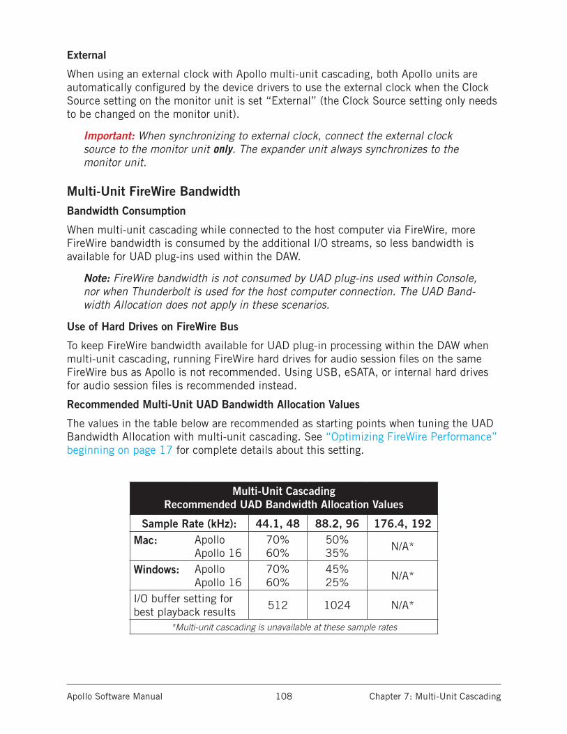
Apollo Software Manual Chapter 7: Multi-Unit Cascading 108
External
When using an external clock with Apollo multi-unit cascading, both Apollo units are automatically configured by the device drivers to use the external clock when the Clock Source setting on the monitor unit is set “External” (the Clock Source setting only needs to be changed on the monitor unit).
Important: When synchronizing to external clock, connect the external clock source to the monitor unit only. The expander unit always synchronizes to the monitor unit.
Multi-Unit FireWire BandwidthBandwidth Consumption
When multi-unit cascading while connected to the host computer via FireWire, more FireWire bandwidth is consumed by the additional I/O streams, so less bandwidth is available for UAD plug-ins used within the DAW.
Note: FireWire bandwidth is not consumed by UAD plug-ins used within Console, nor when Thunderbolt is used for the host computer connection. The UAD Band-width Allocation does not apply in these scenarios.
Use of Hard Drives on FireWire Bus
To keep FireWire bandwidth available for UAD plug-in processing within the DAW when multi-unit cascading, running FireWire hard drives for audio session files on the same FireWire bus as Apollo is not recommended. Using USB, eSATA, or internal hard drives for audio session files is recommended instead.
Recommended Multi-Unit UAD Bandwidth Allocation Values
The values in the table below are recommended as starting points when tuning the UAD Bandwidth Allocation with multi-unit cascading. See “Optimizing FireWire Performance” beginning on page 17 for complete details about this setting.
Multi-Unit Cascading Recommended UAD Bandwidth Allocation Values
Sample Rate (kHz): 44.1, 48 88.2, 96 176.4, 192Mac: Apollo
Apollo 1670% 60%
50% 35%
N/A*
Windows: Apollo Apollo 16
70% 60%
45% 25%
N/A*
I/O buffer setting for best playback results
512 1024 N/A*
*Multi-unit cascading is unavailable at these sample rates

Apollo Software Manual Chapter 7: Multi-Unit Cascading 109
Cascaded Unit TabsMonitor/Expander Designation
A second Unit Tab appears when multi-unit cascading. The unit tab ordering defines the monitor/expander software designations. The tab on the left always represents the moni-tor unit; the tab on the right represents the expander unit.
Expander Unit Removal
If the expander unit is powered down or removed from the system, the expander unit’s tab can be deleted. To delete the unit tab, right-click on the tab and select “Delete” from the menu.
Note: If the expander unit is powered down or removed from the system, the expander unit’s tab must be deleted before the sample rate can be changed to 176.4 kHz or 192 kHz.
Monitor/Expander Swap
The monitor/expander designations are associated to the hardware ID of each unit. If the hardware wiring setup is reversed to change the monitor and expander designations, Console must be manually switched to reflect the hardware change. This is accomplished by re-ordering the tabs in Console.
Swapping the Unit Tab order
To swap the monitor and expander designation ordering in Console, click+hold a unit tab, then drag it to the other tab. A gray double arrow appears when a tab is “grabbed” and the swap is performed when the double arrow is orange and the mouse is released.
Important: Swapping the monitor/expander order changes the driver I/O configura-tion. Quit all audio applications before performing this action.
Console Recall Session ManagementSingle-to-Multi Session
If a Console session was created and saved with a single-unit setup and the session is subsequently opened with a multi-unit setup, the expander unit is automatically added to the session (a second unit tab is added to the session) and the number of Console inputs expands accordingly.
Multi-to-Single Session
If a Console session was created and saved with a multi-unit setup and the session is subsequently opened with a single-unit setup, the expander unit is retained in the ses-sion, but the host status indicator “dot” will be red indicating the expander unit is recog-nized. The expander unit can be removed from the session via the Identify and Rename Menu if desired.
Apollo Software Manual Chapter 7: Multi-Unit Cascading 110
ConstraintsCertain features and/or I/O streams are reduced when multi-unit cascading due to limited audio bandwidth or technical constraints required to maintain integrated mix buses with Realtime UAD Processing capabilities. These constraints are listed below.
Auxiliary 2 (Apollo only)
• Aux bus 2 is unavailable when multi-unit cascading with Apollo.
High Sample Rates
176.4 kHz and 192 kHz
• Multi-unit cascading is unavailable at sample rates of 176.4 kHz or 192 kHz.
88.2 kHz and 96 kHz (Apollo only)
• Both ADAT ports must be used for S/MUX connections when multi-unit cascading at sample rates of 88.2 kHz or 96 kHz.
PT Mode
• Avid Pro Tools allows 32 channels of I/O with non-Avid branded audio interfaces. Because audio streams exceed this count when multi-unit cascading, some Apollo I/O channels are unavailable in PT Mode when multi-unit cascading. The specific Apollo channel numbers and names that are available when PT Mode is active are listed in the “Driver I/O Tables” on page 119.
Combining Different Apollo Models
• Combining Apollo with Apollo 16 is an unsupported configuration.• Apollo Twin cannot be used with multi-unit cascading.
Apollo Software Manual Chapter 8: Latency & Apollo 111
Chapter 8: Latency & Apollo
Delay Compensation with Apollo
System Latency OverviewSystem latency encapsulates all latencies induced within the typical digital audio work-station environment. See “Latency Basics” on page 115 for a detailed overview of where, when, and how latency is induced in this environment.
Driver ReportingAny system latency that is induced by Apollo’s I/O, Console, and/or UAD Powered Plug-Ins is reported by Apollo’s device drivers to the host audio software that is using the device.
The host software uses this reported device latency for its automatic delay compensation (ADC) engine. When properly configured in the DAW, ADC maintains phase coherency (time alignment) throughout the recording, overdubbing, and mixing process.
Automatic Delay Compensation in the DAWGenerally speaking, ADC should be enabled in the DAW when using Apollo, regardless of whether or not Console is used concurrently. The DAW’s ADC will perform the necessary housekeeping to keep tracks phase-aligned, regardless of the latency source (if any).
Input Delay Compensation in ConsoleConsole has automatic Input Delay Compensation (IDC), which is controlled by the Input Delay Compensation menu in Console Settings. Console IDC maintains phase alignment across all Console’s analog and digital inputs when Upsampled UAD Plug-Ins are used in Console.
How Console IDC worksConsole IDC automatically adds small amounts of delay to each Console input that is not delayed by upsampled plug-ins, so all Console inputs are still phase aligned. In other words, all compensated inputs are automatically delayed by the same amount.
Upsampled UAD plug-insSome UAD plug-ins are upsampled, meaning their internal sample rate is increased to achieve sonic design goals. When upsampled UAD plug-ins are used in Console, addi-tional latency is induced in the channel(s) using the plug-in(s).

Apollo Software Manual Chapter 8: Latency & Apollo 112
Although the latency added by upsampled UAD plug-ins is negligible (typically between 0-300 samples, depending on the plug-in and sample rate), this extra latency can affect phase coherency in a session. For specific latency values, see “Upsampled UAD Plug-Ins Table” on page 114.
For example, if two microphones are used on an acoustic source (such as a drum kit) and an upsampled plug-in is used on one of the mic channels but not the other, the phase of the two mic channels will no longer be aligned.
When To Use Console Input Delay CompensationConsole IDC is required to maintain phase alignment only when BOTH of the following conditions are active:
1. Multiple Console inputs are used for a single source (such as a drum kit using multiple microphones), and
2. Any of those input channels contain upsampled UAD plug-ins.
Tip: When IDC is not needed, disable Console IDC for the lowest possible input latency.
Effect of Console’s IDC settingIn Console
In Console, the amount of delay added by the IDC engine is automatic. Only the mini-mum amount of delay actually required to compensate the input(s) is applied (up to the maximum value of the setting), maintaining the lowest possible latency for phase align-ment at all times.
For example: When the IDC value is Short (100 samples – the default value) and only 31 samples is actually required to compensate, then only 31 samples of delay will be ap-plied to the other Console inputs.
In the DAW
In the DAW, the amount of delay added by Console’s IDC engine is static. The extra samples are always added to all inputs in the DAW, even if no upsampled plug-ins are active. However, this overall additional input latency is reported by Apollo’s drivers, so it is automatically compen-sated by the DAW’s ADC.
For example: When the IDC value is Short (100 samples – the default value) and only 31 samples is actually required to compensate, 100 samples is still added to all inputs in the DAW. If using software monitoring via the DAW, the extra (unnecessary) delay could be detected.
Note: By default, Console Input Delay Compensation is enabled with the Short value (100 samples).
Input Delay Compensation Values
Setting Name Extra Delay (samples)
Off 0
Short 100
Medium 200
Long 1000

Apollo Software Manual Chapter 8: Latency & Apollo 113
Software monitoring with Console IDC
When software monitoring via the DAW and Console IDC is enabled, the lowest effective Console IDC setting is recommended to minimize monitoring latency. If using Console for monitoring and software monitoring via the DAW is disabled, the IDC value isn’t as criti-cal because Console will dynamically deliver the lowest possible monitoring latency.
UAD-2 DSP Resources
Console IDC uses a small percentage of Apollo’s UAD-2 DSP. To maximize DSP resource availability for UAD plug-ins, disable Console IDC if it is not needed.
Special Cases: UAD Precision Multiband and UAD Ampex ATR-102
These two upsampled UAD plug-ins have extra latency values that exceed the capacity of Console’s IDC engine even at the maximum setting (Long). These plug-ins are designed to be used on outputs of a DAW during mixdown, where latency is not a consideration. If using these plug-ins in Console, the Input Delay Compensation feature may need to be disabled or ignored.

Apollo Software Manual Chapter 8: Latency & Apollo 114
Upsampled UAD Plug-Ins TableThe table below lists the additional latency produced by upsampled UAD plug-ins.
Sample Rate (kHz)
UAD Powered Plug-In 44.1 48 88.2 96 176.4 192
Ampex ATR-102* 2262 2455 4408 4798 8818 9598
Helios Type 69Harrison 32CNeve 1073 Legacy, 1081, 31102Precision EQPultec EQP-1A LegacyPultec-Pro LegacyPultec HLF-3CSSL E Channel StripTrident A-Range
31 31 13 13 0 0
API 550AAPI Vision Console Channel StripFairchild Tube Limiter CollectionFATSO Jr./Sr.Massive PassiveMoog FilterNeve 1073 (newer model w/preamp)Neve 33609Pultec EQP-1APultec MEQ-5Studer A800Thermionic Culture VultureUA 1176 Limiter CollectionUA 610 Tube Preamp & EQ Collection
55 55 55 55 88 88
API 560Teletronix LA-2A Leveler Collection
56 56 56 56 89 89
EMT 250 (see note) 75 11 85 24 107 50
Lexicon 224 (see note) 84 79 90 97 107 116
MXR Flanger/Doubler 31 31 0 0 0 0
Precision Limiter 64 69 129 140 259 281
Precision Maximizer 67 67 67 67 42 42
Precision Multiband* 15,360 16,896 30,720 33,792 61,440 66,048
*These UAD plug-ins exceed the capacity of Input Delay Compensation in Console. See “Special Cases: UAD Precision Multiband and UAD Ampex ATR-102” for details.
Note: The EMT 250 and Lexicon 224 anti-aliasing filters for their A/D and D/A conversion are not linear-phase filters; therefore the emulations do not have a latency that is the same at all frequencies. Thus, we cannot report to the delay compensation engines a delay that is correct for all frequencies. The reported value is good at low frequencies, but becomes off at high frequencies.
Apollo Software Manual Chapter 8: Latency & Apollo 115
Latency BasicsLatency (delay) is an inherent factor in digital audio systems because of A/D-D/A conver-sion, I/O buffering in the DAW, plug-in signal processing, and other aspects.
Although there are ways to mitigate latency (such as delay compensation and/or low-la-tency monitoring), it always exists to some degree when working with systems that com-bine analog and digital audio. These concepts are explained in greater detail below.
Audio Interface LatencyEvery audio interface that performs A/D and/or D/A conversion induces latency as a result of the conversion process. This inherent A/D–D/A latency is essentially undetectable. A/D–D/A latency usually depends on the sample rate, with higher sample rates inducing less latency (higher rates = less time required for conversion).
An audio interface’s “analog I/O round-trip latency” specification refers to how long it takes for an analog signal at an interface input to reappear at the same interface’s analog output after both A/D and D/A conversion. Apollo’s audio interface analog I/O round-trip latency is 1.1 milliseconds at a sample rate of 96 kHz.
Console Mixer LatencyApollo’s Console Mixer is used for low-latency monitoring (cue mixing) of Apollo’s analog and digital inputs. Using Console to monitor Apollo’s inputs may or may not add to the inherent analog I/O round-trip latency, depending on how it is configured:
Console without UAD plug-ins – When Console is used without UAD plug-ins, monitor-ing Apollo’s inputs via Console does not add any latency. In this configuration, Apollo’s analog I/O round-trip latency is still 1.1 milliseconds at 96 kHz.
Console with Realtime UAD Processing – When Console is used for Realtime UAD Pro-cessing with UAD Powered Plug-Ins that are not upsampled, monitoring Apollo’s inputs via Console does not add any latency.
In this configuration, Apollo’s analog I/O round-trip latency is still 1.1 milliseconds at 96 kHz, even if up to four UAD (non-upsampled) plug-ins are serially “stacked” (chained) on a single Apollo analog and/or digital input.
Multiple Apollo inputs can have up to four UAD (non-upsampled) plug-ins each (up to the limit of available DSP resources); this configuration also does not add any latency.
Note: Upsampled UAD plug-ins add latency when used in Console or a DAW. See “Upsampled UAD Plug-Ins” below for details.
Console Auxiliary Buses – The outputs of the auxiliary buses in Console have 32 samples of additional latency. This is necessary to maintain the lowest possible input latency.
Apollo Software Manual Chapter 8: Latency & Apollo 116
Upsampled UAD Plug-InsSome UAD Powered Plug-Ins are upsampled, meaning their internal sample rate is in-creased to achieve sonic design goals. Depending on the session sample rate, upsampled UAD plug-ins can add additional latency when used in the Console Mixer and/or a DAW.
Although the latency added by upsampled UAD plug-ins is negligible (typically between 0-300 samples, depending on the plug-in and sample rate), this extra latency can affect phase coherency in a session. However, phase is managed automatically by Input Delay Compensation in Console and Automatic Delay Compensation in the DAW.
Note: For specific values, see “Upsampled UAD Plug-Ins Table” on page 114.
DAW LatencyMost DAWs use I/O buffering to shuttle audio data back and forth between the audio in-terface and the DAW. This I/O buffering induces additional latency with any audio inter-face (not just Apollo).
I/O Buffer Size
The amount of DAW latency is usually determined by the DAW’s I/O interface buffer size setting. Low buffer sizes reduce latency, but increase the host computer’s CPU loading. If the buffer size is set too low, host CPU overloads and/or audio artifacts such as clicks, distortion, or dropouts can occur.
Monitoring Live Performance During Recording
DAW latency can be a problem during recording when “software monitoring” via the DAW’s mixer, because the buffering delay is a distraction; an artist cannot hear their per-formance in realtime. DAW latency when recording with Apollo is mitigated by using the Console Mixer for live performance monitoring, where buffering latency does not apply.
Time-Alignment Of Newly-Recorded Tracks With Previously-Recorded Tracks
Dealing with latency is also important with DAWs for time-alignment of newly-recorded tracks and previously-recorded tracks which are inevitably shifted from the I/O buffering process.
The solution is to use the automatic delay compensation (“ADC”) feature of the DAW. Most modern DAWs, including Console, have automatic delay compensation. For more information about system latency and its compensation, see “Delay Compensation with Apollo” on page 111.
Apollo Software Manual Chapter 8: Latency & Apollo 117
UAD-2 DSP LatencyWhen UAD Powered Plug-Ins are used within a DAW (not Console), I/O buffering is used to shuttle audio data back and forth between the UAD-2 inside Apollo and the DAW, which induces additional latency.
This UAD-2 DSP “DAW processing method” latency is determined by the I/O Buffer Size setting. This latency is unrelated to the (indiscernible) audio interface I/O latency (they are separate processes).
UAD-2 DSP latency makes tracking through UAD plug-ins in the DAW via software moni-toring problematic for the performer because again, an artist cannot hear their perfor-mance in realtime.
The issue of UAD-2 DSP latency when recording with Apollo is eliminated by using the Console Mixer for live performance monitoring with optional Realtime UAD Processing, where buffering latency does not apply.
Does all this latency stuff really matter?With Apollo, not really. Performance latency is not a factor because of Console’s low la-tency monitoring; and recording (track alignment) latency during recording, overdubbing, and mixing is automatically compensated by Console and the DAW.

Apollo Software Manual Chapter 9: Device Drivers 118
Chapter 9: Device Drivers
Apollo Drivers OverviewThe Apollo device drivers are the low-level software files that instruct the computer’s operating system on how to communicate with the Apollo hardware. The drivers are loaded during system startup so that whenever Apollo is connected, the device is ready to accept instructions from the OS. Apollo’s drivers control Apollo’s audio interface, Console Mixer, and UAD-2 functional-ity.
Core Audio and ASIO
Apollo’s audio drivers use the Core Audio (Mac) and ASIO (Windows) APIs. Apollo’s normal (non-DSP) audio interface features are simply seen as Core Audio or ASIO device; therefore any Core Audio/ASIO-compliant software can use Apollo for audio I/O.
UAD Mixer Engine
The Console application and Console Recall plug-in don’t actually communicate directly with Apollo. Instead, they communicate with the UAD Mixer Engine, which is the central software hub for all Console and Console Recall functionality. The UAD Mixer Engine behaves as a server for Apollo’s internal DSP mixer that runs in the background, so Console does not have to be open for Apollo to function.
The UAD Mixer Engine is a system-level application that is automatically launched during sys-tem startup and is always running during normal operation. The UAD System Menu is it’s only interface, which can be accessed from the OS X Menu Bar (Mac), or the Windows System Tray (Windows).
Driver I/O Complement
The specific inputs and outputs that are available to the DAW depends on the active configura-tion. The I/O complement changes when PT Mode is enabled, at high sample rates, and when multi-unit cascading. The specific I/O complements are listed in the Driver I/O Tables in this chapter.
Driver Names and Numbers
Apollo’s drivers describe all I/O channels by name and number, but what is actually displayed in the DAW’s I/O assignment lists depends on each particular DAW. Names are not displayed by all DAWs (e.g., Ableton Live), or the driver name display mode may need to be changed in the DAW (e.g., Apple Logic Pro).
Virtual I/O
Apollo’s device drivers carry various virtual (software only) input and output channels in addition to those directly associated with the hardware inputs and outputs. The virtual channels consist of all of Apollo’s bus outputs (the main monitor mix and all channel send mixes) and Console’s virtual inputs. Virtual I/O facilitates highly flexible signal routing via the DAW. See “Virtual I/O” on page 98 for details about this feature.
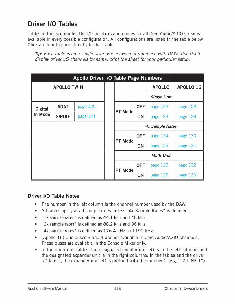
Apollo Software Manual Chapter 9: Device Drivers 119
Driver I/O TablesTables in this section list the I/O numbers and names for all Core Audio/ASIO streams available in every possible configuration. All configurations are listed in the table below. Click an item to jump directly to that table.
Tip: Each table is on a single page. For convenient reference with DAWs that don’t display driver I/O channels by name, print the sheet for your particular setup.
Apollo Driver I/O Table Page Numbers
APOLLO TWIN APOLLO APOLLO 16
Single Unit
Digital In Mode
ADAT page 120PT Mode
OFF page 122 page 128
S/PDIF page 121 ON page 123 page 129
4x Sample Rates
PT ModeOFF page 124 page 130
ON page 125 page 131
Multi-Unit
PT ModeOFF page 126 page 132
ON page 127 page 133
Driver I/O Table Notes• The number in the left column is the channel number used by the DAW.• All tables apply at all sample rates unless “4x Sample Rates” is denoted.• “1x sample rates” is defined as 44.1 kHz and 48 kHz.• “2x sample rates” is defined as 88.2 kHz and 96 kHz.• “4x sample rates” is defined as 176.4 kHz and 192 kHz.• (Apollo 16) Cue buses 3 and 4 are not available in Core Audio/ASIO channels.
These buses are available in the Console Mixer only. • In the multi-unit tables, the designated monitor unit I/O is in the left columns and
the designated expander unit is in the right columns. In the tables and the driver I/O labels, the expander unit I/O is prefixed with the number 2 (e.g., “2 LINE 1”).
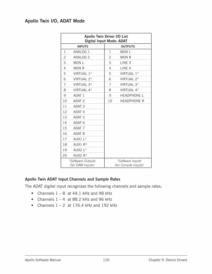
Apollo Software Manual Chapter 9: Device Drivers 120
Apollo Twin I/O, ADAT Mode
Apollo Twin Driver I/O List Digital Input Mode: ADAT
INPUTS OUTPUTS
1 ANALOG 1 1 MON L
2 ANALOG 2 2 MON R
3 MON L 3 LINE 3
4 MON R 4 LINE 4
5 VIRTUAL 1* 5 VIRTUAL 1*
6 VIRTUAL 2* 6 VIRTUAL 2*
7 VIRTUAL 3* 7 VIRTUAL 3*
8 VIRTUAL 4* 8 VIRTUAL 4*
9 ADAT 1 9 HEADPHONE L
10 ADAT 2 10 HEADPHONE R
11 ADAT 3
12 ADAT 4
13 ADAT 5
14 ADAT 6
15 ADAT 7
16 ADAT 8
17 AUX1 L*
18 AUX1 R*
19 AUX2 L*
20 AUX2 R*
*Software Outputs (for DAW inputs)
*Software Inputs (for Console inputs)
Apollo Twin ADAT Input Channels and Sample Rates
The ADAT digital input recognizes the following channels and sample rates:
• Channels 1 – 8 at 44.1 kHz and 48 kHz• Channels 1 – 4 at 88.2 kHz and 96 kHz• Channels 1 – 2 at 176.4 kHz and 192 kHz

Apollo Software Manual Chapter 9: Device Drivers 121
Apollo Twin I/O, S/PDIF Mode
Apollo Twin Driver I/O List Digital Input Mode: S/PDIF
INPUTS OUTPUTS
1 ANALOG 1 1 MON L
2 ANALOG 2 2 MON R
3 MON L 3 LINE 3
4 MON R 4 LINE 4
5 VIRTUAL 1* 5 VIRTUAL 1*
6 VIRTUAL 2* 6 VIRTUAL 2*
7 VIRTUAL 3* 7 VIRTUAL 3*
8 VIRTUAL 4* 8 VIRTUAL 4*
9 S/PDIF L 9 HEADPHONE L
10 S/PDIF R 10 HEADPHONE R
11 AUX1 L*
12 AUX1 R*
13 AUX2 L*
14 AUX2 R*
*Software Outputs (for DAW inputs)
*Software Inputs (for Console inputs)
Note: Apollo Twin recognizes S/PDIF digital input at sample rates up to 96 kHz.

Apollo Software Manual Chapter 9: Device Drivers 122
Apollo I/O, Single Unit, PT Mode Off
Apollo Driver I/O List Single Unit – PT Mode Off
INPUTS OUTPUTS
1 MIC/LINE/Hi-Z 1 1 MON L
2 MIC/LINE/Hi-Z 2 2 MON R
3 MIC/LINE 3 3 LINE 1
4 MIC/LINE 4 4 LINE 2
5 LINE 5 5 LINE 3
6 LINE 6 6 LINE 4
7 LINE 7 7 LINE 5
8 LINE 8 8 LINE 6
9 ADAT 1 9 LINE 7
10 ADAT 2 10 LINE 8
11 ADAT 3 11 ADAT 1
12 ADAT 4 12 ADAT 2
13 ADAT 5 13 ADAT 3
14 ADAT 6 14 ADAT 4
15 ADAT 7 15 ADAT 5
16 ADAT 8 16 ADAT 6
17 S/PDIF L 17 ADAT 7
18 S/PDIF R 18 ADAT 8
19 VIRTUAL 1* 19 S/PDIF L
20 VIRTUAL 2* 20 S/PDIF R
21 VIRTUAL 3* 21 VIRTUAL 1*
22 VIRTUAL 4* 22 VIRTUAL 2*
23 MON L* 23 VIRTUAL 3*
24 MON R* 24 VIRTUAL 4*
25 AUX1 L* 25 HP1 L
26 AUX1 R* 26 HP1 R
27 AUX2 L* 27 HP2 L
28 AUX2 R* 28 HP2 R
29 HP1 L*
30 HP1 R*
31 HP2 L*
32 HP2 R*
*Software Outputs (for DAW inputs)
*Software Inputs (for Console inputs)

Apollo Software Manual Chapter 9: Device Drivers 123
Apollo I/O, Single Unit, PT Mode On
Apollo Driver I/O List Single Unit – PT Mode On
INPUTS OUTPUTS
1 NULL 1 1 MON L
2 NULL 2 2 MON R
3 MIC/LINE/Hi-Z 1 3 LINE 1
4 MIC/LINE/Hi-Z 2 4 LINE 2
5 MIC/LINE 3 5 LINE 3
6 MIC/LINE 4 6 LINE 4
7 LINE 5 7 LINE 5
8 LINE 6 8 LINE 6
9 LINE 7 9 LINE 7
10 LINE 8 10 LINE 8
11 ADAT 1 11 ADAT 1
12 ADAT 2 12 ADAT 2
13 ADAT 3 13 ADAT 3
14 ADAT 4 14 ADAT 4
15 ADAT 5 15 ADAT 5
16 ADAT 6 16 ADAT 6
17 ADAT 7 17 ADAT 7
18 ADAT 8 18 ADAT 8
19 S/PDIF L 19 S/PDIF L
20 S/PDIF R 20 S/PDIF R
21 VIRTUAL 1* 21 VIRTUAL 1*
22 VIRTUAL 2* 22 VIRTUAL 2*
23 MON L* 23 VIRTUAL 3*
24 MON R* 24 VIRTUAL 4*
25 AUX1 L* 25 HP1 L
26 AUX1 R* 26 HP1 R
27 AUX2 L* 27 HP2 L
28 AUX2 R* 28 HP2 R
29 HP1 L*
30 HP1 R*
31 HP2 L*
32 HP2 R*
*Software Outputs (for DAW inputs)
*Software Inputs (for Console inputs)

Apollo Software Manual Chapter 9: Device Drivers 124
Apollo I/O, Single Unit, PT Mode Off, 4x Sample Rates
Apollo Driver I/O Single Unit – PT Mode Off
176.4 kHz & 192 kHz Sample RatesINPUTS OUTPUTS
1 MIC/LINE/Hi-Z 1 1 MON L
2 MIC/LINE/Hi-Z 2 2 MON R
3 MIC/LINE 3 3 LINE 1
4 MIC/LINE 4 4 LINE 2
5 LINE 5 5 LINE 3
6 LINE 6 6 LINE 4
7 LINE 7 7 LINE 5
8 LINE 8 8 LINE 6
9 ADAT 1 9 LINE 7
10 ADAT 2 10 LINE 8
11 ADAT 3 11 ADAT 1
12 ADAT 4 12 ADAT 2
13 S/PDIF L 13 ADAT 3
14 S/PDIF R 14 ADAT 4
15 MON L* 15 S/PDIF L
16 MON R* 16 S/PDIF R
17 AUX1 L* 17 HP1 L
18 AUX1 R* 18 HP1 R
19 HP1 L* 19 HP2 L
20 HP1 R* 20 HP2 R
21 HP2 L*
22 HP2 R*
*Software Outputs (for DAW inputs)
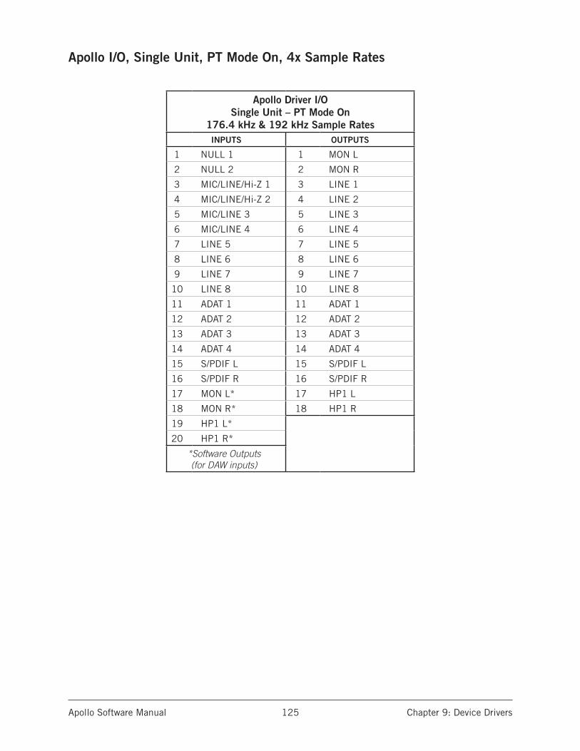
Apollo Software Manual Chapter 9: Device Drivers 125
Apollo I/O, Single Unit, PT Mode On, 4x Sample Rates
Apollo Driver I/O Single Unit – PT Mode On
176.4 kHz & 192 kHz Sample RatesINPUTS OUTPUTS
1 NULL 1 1 MON L
2 NULL 2 2 MON R
3 MIC/LINE/Hi-Z 1 3 LINE 1
4 MIC/LINE/Hi-Z 2 4 LINE 2
5 MIC/LINE 3 5 LINE 3
6 MIC/LINE 4 6 LINE 4
7 LINE 5 7 LINE 5
8 LINE 6 8 LINE 6
9 LINE 7 9 LINE 7
10 LINE 8 10 LINE 8
11 ADAT 1 11 ADAT 1
12 ADAT 2 12 ADAT 2
13 ADAT 3 13 ADAT 3
14 ADAT 4 14 ADAT 4
15 S/PDIF L 15 S/PDIF L
16 S/PDIF R 16 S/PDIF R
17 MON L* 17 HP1 L
18 MON R* 18 HP1 R
19 HP1 L*
20 HP1 R*
*Software Outputs (for DAW inputs)

Apollo Software Manual Chapter 9: Device Drivers 126
Apollo I/O, Multi-Unit, PT Mode Off
Apollo Driver I/O List Multi-Unit – PT Mode Off
INPUTS OUTPUTS
MONITOR UNIT EXPANDER UNIT MONITOR UNIT EXPANDER UNIT
1 MIC/LINE/Hi-Z 1 23 2 MIC/LINE/Hi-Z 1 1 MON L 29 2 LINE 1
2 MIC/LINE/Hi-Z 2 24 2 MIC/LINE/Hi-Z 2 2 MON R 30 2 LINE 2
3 MIC/LINE 3 25 2 MIC/LINE 3 3 LINE 1 31 2 LINE 3
4 MIC/LINE 4 26 2 MIC/LINE 4 4 LINE 2 32 2 LINE 4
5 LINE 5 27 2 LINE 5 5 LINE 3 33 2 LINE 5
6 LINE 6 28 2 LINE 6 6 LINE 4 34 2 LINE 6
7 LINE 7 29 2 LINE 7 7 LINE 5 35 2 LINE 7
8 LINE 8 30 2 LINE 8 8 LINE 6 36 2 LINE 8
9 S/PDIF L 31 2 ADAT 1 9 LINE 7 37 2 S/PDIF L
10 S/PDIF R 32 2 ADAT 2 10 LINE 8 38 2 S/PDIF R
11 VIRTUAL 1* 33 2 ADAT 3 11 ADAT 1 39 2 VIRTUAL 1*
12 VIRTUAL 2* 34 2 ADAT 4 12 ADAT 2 40 2 VIRTUAL 2*
13 VIRTUAL 3* 35 2 ADAT 5 13 ADAT 3 41 2 VIRTUAL 3*
14 VIRTUAL 4* 36 2 ADAT 6 14 ADAT 4 42 2 VIRTUAL 4*
15 MON L* 37 2 ADAT 7 15 ADAT 5
16 MON R* 38 2 ADAT 8 16 ADAT 6
17 AUX1 L* 39 2 S/PDIF L 17 ADAT 7
18 AUX1 R* 40 2 S/PDIF R 18 ADAT 8
19 HP1 L* 41 2 VIRTUAL 1* 19 S/PDIF L
20 HP1 R* 42 2 VIRTUAL 2* 20 S/PDIF R
21 HP2 L* 43 2 VIRTUAL 3* 21 VIRTUAL 1*
22 HP2 R* 44 2 VIRTUAL 4* 22 VIRTUAL 2*
23 VIRTUAL 3*
24 VIRTUAL 4*
25 HP1 L*
26 HP1 R*
27 HP2 L*
28 HP2 R*
*Software Outputs (for DAW inputs)
*Software Inputs (for Console inputs)
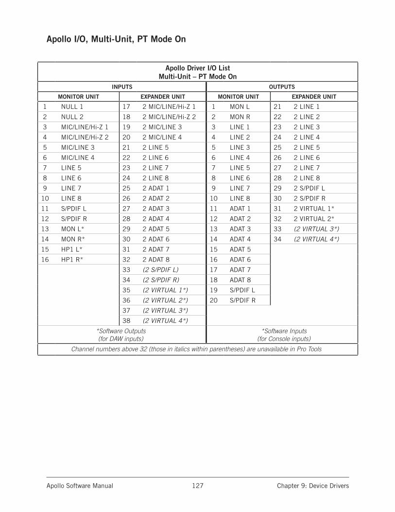
Apollo Software Manual Chapter 9: Device Drivers 127
Apollo I/O, Multi-Unit, PT Mode On
Apollo Driver I/O List Multi-Unit – PT Mode On
INPUTS OUTPUTS
MONITOR UNIT EXPANDER UNIT MONITOR UNIT EXPANDER UNIT
1 NULL 1 17 2 MIC/LINE/Hi-Z 1 1 MON L 21 2 LINE 1
2 NULL 2 18 2 MIC/LINE/Hi-Z 2 2 MON R 22 2 LINE 2
3 MIC/LINE/Hi-Z 1 19 2 MIC/LINE 3 3 LINE 1 23 2 LINE 3
4 MIC/LINE/Hi-Z 2 20 2 MIC/LINE 4 4 LINE 2 24 2 LINE 4
5 MIC/LINE 3 21 2 LINE 5 5 LINE 3 25 2 LINE 5
6 MIC/LINE 4 22 2 LINE 6 6 LINE 4 26 2 LINE 6
7 LINE 5 23 2 LINE 7 7 LINE 5 27 2 LINE 7
8 LINE 6 24 2 LINE 8 8 LINE 6 28 2 LINE 8
9 LINE 7 25 2 ADAT 1 9 LINE 7 29 2 S/PDIF L
10 LINE 8 26 2 ADAT 2 10 LINE 8 30 2 S/PDIF R
11 S/PDIF L 27 2 ADAT 3 11 ADAT 1 31 2 VIRTUAL 1*
12 S/PDIF R 28 2 ADAT 4 12 ADAT 2 32 2 VIRTUAL 2*
13 MON L* 29 2 ADAT 5 13 ADAT 3 33 (2 VIRTUAL 3*)
14 MON R* 30 2 ADAT 6 14 ADAT 4 34 (2 VIRTUAL 4*)
15 HP1 L* 31 2 ADAT 7 15 ADAT 5
16 HP1 R* 32 2 ADAT 8 16 ADAT 6
33 (2 S/PDIF L) 17 ADAT 7
34 (2 S/PDIF R) 18 ADAT 8
35 (2 VIRTUAL 1*) 19 S/PDIF L
36 (2 VIRTUAL 2*) 20 S/PDIF R
37 (2 VIRTUAL 3*)
38 (2 VIRTUAL 4*)
*Software Outputs (for DAW inputs)
*Software Inputs (for Console inputs)
Channel numbers above 32 (those in italics within parentheses) are unavailable in Pro Tools
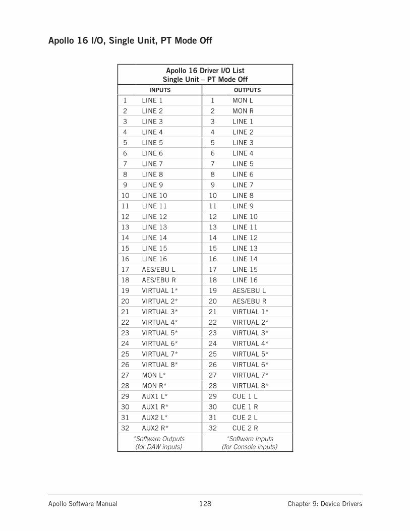
Apollo Software Manual Chapter 9: Device Drivers 128
Apollo 16 I/O, Single Unit, PT Mode Off
Apollo 16 Driver I/O List Single Unit – PT Mode Off
INPUTS OUTPUTS
1 LINE 1 1 MON L
2 LINE 2 2 MON R
3 LINE 3 3 LINE 1
4 LINE 4 4 LINE 2
5 LINE 5 5 LINE 3
6 LINE 6 6 LINE 4
7 LINE 7 7 LINE 5
8 LINE 8 8 LINE 6
9 LINE 9 9 LINE 7
10 LINE 10 10 LINE 8
11 LINE 11 11 LINE 9
12 LINE 12 12 LINE 10
13 LINE 13 13 LINE 11
14 LINE 14 14 LINE 12
15 LINE 15 15 LINE 13
16 LINE 16 16 LINE 14
17 AES/EBU L 17 LINE 15
18 AES/EBU R 18 LINE 16
19 VIRTUAL 1* 19 AES/EBU L
20 VIRTUAL 2* 20 AES/EBU R
21 VIRTUAL 3* 21 VIRTUAL 1*
22 VIRTUAL 4* 22 VIRTUAL 2*
23 VIRTUAL 5* 23 VIRTUAL 3*
24 VIRTUAL 6* 24 VIRTUAL 4*
25 VIRTUAL 7* 25 VIRTUAL 5*
26 VIRTUAL 8* 26 VIRTUAL 6*
27 MON L* 27 VIRTUAL 7*
28 MON R* 28 VIRTUAL 8*
29 AUX1 L* 29 CUE 1 L
30 AUX1 R* 30 CUE 1 R
31 AUX2 L* 31 CUE 2 L
32 AUX2 R* 32 CUE 2 R
*Software Outputs (for DAW inputs)
*Software Inputs (for Console inputs)

Apollo Software Manual Chapter 9: Device Drivers 129
Apollo 16 I/O, Single Unit, PT Mode On
Apollo 16 Driver I/O List Single Unit – PT Mode On
INPUTS OUTPUTS
1 NULL 1 1 MON L
2 NULL 2 2 MON R
3 LINE 1 3 LINE 1
4 LINE 2 4 LINE 2
5 LINE 3 5 LINE 3
6 LINE 4 6 LINE 4
7 LINE 5 7 LINE 5
8 LINE 6 8 LINE 6
9 LINE 7 9 LINE 7
10 LINE 8 10 LINE 8
11 LINE 9 11 LINE 9
12 LINE 10 12 LINE 10
13 LINE 11 13 LINE 11
14 LINE 12 14 LINE 12
15 LINE 13 15 LINE 13
16 LINE 14 16 LINE 14
17 LINE 15 17 LINE 15
18 LINE 16 18 LINE 16
19 AES/EBU L 19 AES/EBU L
20 AES/EBU R 20 AES/EBU R
21 VIRTUAL 1* 21 VIRTUAL 1*
22 VIRTUAL 2* 22 VIRTUAL 2*
23 VIRTUAL 3* 23 VIRTUAL 3*
24 VIRTUAL 4* 24 VIRTUAL 4*
25 VIRTUAL 5* 25 VIRTUAL 5*
26 VIRTUAL 6* 26 VIRTUAL 6*
27 MON L* 27 VIRTUAL 7*
28 MON R* 28 VIRTUAL 8*
29 AUX1 L* 29 CUE 1 L
30 AUX1 R* 30 CUE 1 R
31 AUX2 L* 31 CUE 2 L
32 AUX2 R* 32 CUE 2 R
*Software Outputs (for DAW inputs)
*Software Inputs (for Console inputs)
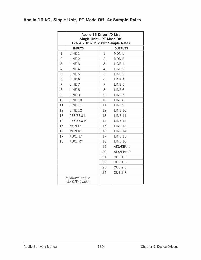
Apollo Software Manual Chapter 9: Device Drivers 130
Apollo 16 I/O, Single Unit, PT Mode Off, 4x Sample Rates
Apollo 16 Driver I/O List Single Unit – PT Mode Off
176.4 kHz & 192 kHz Sample RatesINPUTS OUTPUTS
1 LINE 1 1 MON L
2 LINE 2 2 MON R
3 LINE 3 3 LINE 1
4 LINE 4 4 LINE 2
5 LINE 5 5 LINE 3
6 LINE 6 6 LINE 4
7 LINE 7 7 LINE 5
8 LINE 8 8 LINE 6
9 LINE 9 9 LINE 7
10 LINE 10 10 LINE 8
11 LINE 11 11 LINE 9
12 LINE 12 12 LINE 10
13 AES/EBU L 13 LINE 11
14 AES/EBU R 14 LINE 12
15 MON L* 15 LINE 13
16 MON R* 16 LINE 14
17 AUX1 L* 17 LINE 15
18 AUX1 R* 18 LINE 16
19 AES/EBU L
20 AES/EBU R
21 CUE 1 L
22 CUE 1 R
23 CUE 2 L
24 CUE 2 R
*Software Outputs (for DAW inputs)

Apollo Software Manual Chapter 9: Device Drivers 131
Apollo 16 I/O, Single Unit, PT Mode On, 4x Sample Rates
Apollo 16 Driver I/O List Single Unit – PT Mode On
176.4 kHz & 192 kHz Sample RatesINPUTS OUTPUTS
1 NULL 1 1 MON L
2 NULL 2 2 MON R
3 LINE 1 3 LINE 1
4 LINE 2 4 LINE 2
5 LINE 3 5 LINE 3
6 LINE 4 6 LINE 4
7 LINE 5 7 LINE 5
8 LINE 6 8 LINE 6
9 LINE 7 9 LINE 7
10 LINE 8 10 LINE 8
11 LINE 9 11 LINE 9
12 LINE 10 12 LINE 10
13 LINE 11 13 LINE 11
14 LINE 12 14 LINE 12
15 AES/EBU L 15 LINE 13
16 AES/EBU R 16 LINE 14
17 MON L* 17 LINE 15
18 MON R* 18 LINE 16
19 AUX1 L* 19 AES/EBU L
20 AUX1 R* 20 AES/EBU R
21 CUE 1 L
22 CUE 1 R
23 CUE 2 L
24 CUE 2 R
*Software Outputs (for DAW inputs)
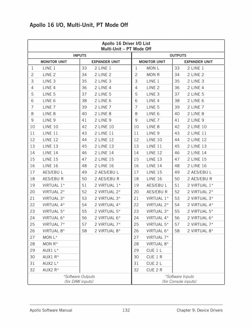
Apollo Software Manual Chapter 9: Device Drivers 132
Apollo 16 I/O, Multi-Unit, PT Mode Off
Apollo 16 Driver I/O List Multi-Unit – PT Mode Off
INPUTS OUTPUTS
MONITOR UNIT EXPANDER UNIT MONITOR UNIT EXPANDER UNIT
1 LINE 1 33 2 LINE 1 1 MON L 33 2 LINE 1
2 LINE 2 34 2 LINE 2 2 MON R 34 2 LINE 2
3 LINE 3 35 2 LINE 3 3 LINE 1 35 2 LINE 3
4 LINE 4 36 2 LINE 4 4 LINE 2 36 2 LINE 4
5 LINE 5 37 2 LINE 5 5 LINE 3 37 2 LINE 5
6 LINE 6 38 2 LINE 6 6 LINE 4 38 2 LINE 6
7 LINE 7 39 2 LINE 7 7 LINE 5 39 2 LINE 7
8 LINE 8 40 2 LINE 8 8 LINE 6 40 2 LINE 8
9 LINE 9 41 2 LINE 9 9 LINE 7 41 2 LINE 9
10 LINE 10 42 2 LINE 10 10 LINE 8 42 2 LINE 10
11 LINE 11 43 2 LINE 11 11 LINE 9 43 2 LINE 11
12 LINE 12 44 2 LINE 12 12 LINE 10 44 2 LINE 12
13 LINE 13 45 2 LINE 13 13 LINE 11 45 2 LINE 13
14 LINE 14 46 2 LINE 14 14 LINE 12 46 2 LINE 14
15 LINE 15 47 2 LINE 15 15 LINE 13 47 2 LINE 15
16 LINE 16 48 2 LINE 16 16 LINE 14 48 2 LINE 16
17 AES/EBU L 49 2 AES/EBU L 17 LINE 15 49 2 AES/EBU L
18 AES/EBU R 50 2 AES/EBU R 18 LINE 16 50 2 AES/EBU R
19 VIRTUAL 1* 51 2 VIRTUAL 1* 19 AES/EBU L 51 2 VIRTUAL 1*
20 VIRTUAL 2* 52 2 VIRTUAL 2* 20 AES/EBU R 52 2 VIRTUAL 2*
21 VIRTUAL 3* 53 2 VIRTUAL 3* 21 VIRTUAL 1* 53 2 VIRTUAL 3*
22 VIRTUAL 4* 54 2 VIRTUAL 4* 22 VIRTUAL 2* 54 2 VIRTUAL 4*
23 VIRTUAL 5* 55 2 VIRTUAL 5* 23 VIRTUAL 3* 55 2 VIRTUAL 5*
24 VIRTUAL 6* 56 2 VIRTUAL 6* 24 VIRTUAL 4* 56 2 VIRTUAL 6*
25 VIRTUAL 7* 57 2 VIRTUAL 7* 25 VIRTUAL 5* 57 2 VIRTUAL 7*
26 VIRTUAL 8* 58 2 VIRTUAL 8* 26 VIRTUAL 6* 58 2 VIRTUAL 8*
27 MON L* 27 VIRTUAL 7*
28 MON R* 28 VIRTUAL 8*
29 AUX1 L* 29 CUE 1 L
30 AUX1 R* 30 CUE 1 R
31 AUX2 L* 31 CUE 2 L
32 AUX2 R* 32 CUE 2 R
*Software Outputs (for DAW inputs)
*Software Inputs (for Console inputs)

Apollo Software Manual Chapter 9: Device Drivers 133
Apollo 16 I/O, Multi-Unit, PT Mode On
Apollo 16 Driver I/O List Multi-Unit – PT Mode On
INPUTS OUTPUTS
MONITOR UNIT EXPANDER UNIT MONITOR UNIT EXPANDER UNIT
1 NULL 1 19 2 LINE 1 1 MON L 19 2 LINE 1
2 NULL 2 20 2 LINE 2 2 MON R 20 2 LINE 2
3 LINE 1 21 2 LINE 3 3 LINE 1 21 2 LINE 3
4 LINE 2 22 2 LINE 4 4 LINE 2 22 2 LINE 4
5 LINE 3 23 2 LINE 5 5 LINE 3 23 2 LINE 5
6 LINE 4 24 2 LINE 6 6 LINE 4 24 2 LINE 6
7 LINE 5 25 2 LINE 7 7 LINE 5 25 2 LINE 7
8 LINE 6 26 2 LINE 8 8 LINE 6 26 2 LINE 8
9 LINE 7 27 2 LINE 9 9 LINE 7 27 2 LINE 9
10 LINE 8 28 2 LINE 10 10 LINE 8 28 2 LINE 10
11 LINE 9 29 2 LINE 11 11 LINE 9 29 2 LINE 11
12 LINE 10 30 2 LINE 12 12 LINE 10 30 2 LINE 12
13 LINE 11 31 2 LINE 13 13 LINE 11 31 2 LINE 13
14 LINE 12 32 2 LINE 14 14 LINE 12 32 2 LINE 14
15 LINE 13 33 (2 LINE 15) 15 LINE 13 33 (2 LINE 15)
16 LINE 14 34 (2 LINE 16) 16 LINE 14 34 (2 LINE 16)
17 LINE 15 35 (2 AES/EBU L) 17 LINE 15 35 (2 AES/EBU L)
18 LINE 16 36 (2 AES/EBU R) 18 LINE 16 36 (2 AES/EBU R)
37 (2 VIRTUAL 1*) 37 (2 VIRTUAL 1*)
38 (2 VIRTUAL 2*) 38 (2 VIRTUAL 2*)
39 (2 VIRTUAL 3*) 39 (2 VIRTUAL 3*)
40 (2 VIRTUAL 4*) 40 (2 VIRTUAL 4*)
41 (2 VIRTUAL 5*) 41 (2 VIRTUAL 5*)
42 (2 VIRTUAL 6*) 42 (2 VIRTUAL 6*)
43 (2 VIRTUAL 7*) 43 (2 VIRTUAL 7*)
44 (2 VIRTUAL 8*) 44 (2 VIRTUAL 8*)
*Software Outputs (for DAW inputs)
*Software Inputs (for Console inputs)
Channel numbers above 32 (those in italics within parentheses) are unavailable within Pro Tools

Apollo Software Manual Glossary 134
Chapter 10: Glossary
A/D An acronym for “Analog to Digital,” which refers to the conversion of analog signals to digital data.
Acronym A word formed from the first letters of other words (e.g., GUI, ADAT, TRS, etc.).
ADAT An acronym for “Alesis Digital Audio Tape.” ADAT was the name given to the Alesis-branded products of the 1990s which recorded eight tracks of digital audio on a standard S-VHS video cassette. The term now generally refers to the 8-channel optical “Lightpipe” connection that is used in a wide range of digital products from many manu-facturers.
AES (sometimes written as “AES/EBU“) The name of a digital audio transfer standard jointly developed by the American-based Audio Engineering Society and the European Broadcast Union. Designed to carry two channels of 16-, 20- or, 24-bit digital audio at sampling rates of up to 192kHz, the most common AES physical interconnect utilizes a 3-conductor 110 ohm twisted pair cable, terminating at standard XLR connectors. (See “Dual Wire” and “Single Wire”)
Analog Literally, an analog is a replica or representation of something. In audio signals, changes in voltage are used to represent changes in acoustic sound pressure. Note that analog audio is a continuous representation, as opposed to the quantized, or discrete “stepped” representation created by digital devices. (See “Digital”)
API Acronym for Application Programming Interface. A software layer between an operat-ing system and third-party hardware (such as an audio interface) and/or software (such as a DAW). For example, a computer OS’s audio API enables audio hardware and audio software from different vendors to communicate with the OS and each other.
ASIO Acronym for Audio Stream Input/Output. ASIO is an audio interface driver protocol for Windows operating systems developed by Steinberg GmbH.
Balanced Audio cabling that uses two twisted conductors enclosed in a single shield, thus allowing relatively long cable runs with minimal signal loss and reduced induced noise such as hum.
Bit A contraction of the words “binary” and “digit,” a bit is a number used in a digi-tal system, and it can have only one of two values: 0 or 1. The number of bits in each sample determines the theoretical maximum dynamic range of the audio data, regardless of sample rate being used. Each additional bit adds approximately 6 dB to the dynamic range of the audio. In addition, the use of more bits helps capture quieter signal more accurately. (See “Sample” and “Dynamic range”)
Bit Depth (See “Bit Resolution”)
Apollo Software Manual Glossary 135
Bit Resolution Often used interchangeably with “bit depth,” this is a term used to de-scribe the number of bits used in a digital recording. Apollo converts analog audio and transmits digital audio with a resolution of 24 bits (thus yielding a theoretical dynamic range of approximately 145 dB), the highest audio interface resolution in common use today. (See “Dynamic Range”)
BNC A bayonet-type coaxial connector often found on video and digital audio equipment, as well as on test devices like oscilloscopes. In digital audio equipment, BNC connec-tors are normally used to carry word clock signals between devices. BNC connectors are named for their type (Bayonet), and their inventors, Paul Neil and Carl Concelman. (See “Word Clock”)
Buffer, buffers, buffering The transference of data in small batches instead of continu-ously. Buffering induces latency (delay) and is inherent in most digital audio systems.
Bus A signal path that carries more than one signal, e.g., a mix bus, auxiliary bus, head-phone bus, etc.
Channel Input Strip A group of controls that pertain only to the functions contained within a particular mixer input channel. In most mixing consoles, the “strips” are dupli-cated for each input.
Class A One design technique used in electronic devices such that their active compo-nents are drawing current and working throughout the full signal cycle, thus yielding a more linear response. This increased linearity results in fewer harmonics generated, hence lower distortion in the output signal.
Condenser Microphone A microphone design that utilizes an electrically charged thin conductive diaphragm stretched close to a metal disk called a backplate. Incoming sound pressure causes the diaphragm to vibrate, in turn causing the capacitance to vary in a like manner, which causes a variance in its output voltage. Condenser microphones tend to have excellent transient response but require an external voltage source, most often in the form of 48 volts of “phantom power.”
Clock In digital audio or video, a clock serves as a timing reference for a system. Every digital device must carry out specified numbers of operations per period of time and at a consistent speed in order for the device to work properly. Digital audio devices such as Apollo normally have an internal clock, and are also capable of locking to external clock routed from other digital devices. In order to avoid signal degradation or undesirable audible artifacts, it is absolutely critical that all digital devices that are interconnected in a system be locked to the same clock.
Clock Distribution Refers to the process of routing a master clock signal (either from an internal clock or an external source) to multiple devices by means of multiple outputs, thus removing the need to cascade the clock through external devices, which can de-grade the signal.
Core Audio The audio API for Mac OS X.
D/A Acronym for “Digital to Analog,” which refers to the conversion of a digital data to an analog signal.
Apollo Software Manual Glossary 136
DAW Acronym for “Digital Audio Workstation” – that is, any device that can record, play back, edit, and process digital audio.
dB Abbreviation for “decibel,” a logarithmic unit of measure used to determine, among other things, power ratios, voltage gain, and sound pressure levels.
dBm Abbreviation for “decibels as referenced to milliwatt,” dissipated in a standard load of 600 ohms. 1 dBm into 600 ohms results in 0.775 volts RMS.
dBV Abbreviation for “decibels as referenced to voltage,” without regard for impedance; thus, one volt equals one dBV.
DI Acronym for “Direct Inject” or “Direct Input,” a recording technique whereby the signal from a high-impedance instrument such as electric guitar or bass is routed to an input. DI into mixer or tape recorder inputs often employ use of a “DI box,” which raises the signal to the correct voltage level at the right impedance.
Digital Information or data that is stored or communicated as a series of bits (binary digits, with values of 0 or 1). Digital audio refers to the representation of varying sound pressure levels by means of a series of numbers. (See “Analog” and “Bit”)
Dither Minute amounts of shaped noise added intentionally to a digital recording in order to reduce a form of distortion known as “quantization noise” and aid in low level sound resolution.
Dry Refers to a signal that is unprocessed, e.g., recording a dry signal. The antonym of a “wet” signal.
DSP Acronym for “Digital Signal Processing” (or “Digital Signal Processor.”)
DSP Accelerator A device dedicated to digital signal processing. UAD-2 devices are DSP accelerators.
Dynamic Microphone A type of microphone that generates signal with the use of a very thin, light diaphragm which moves in response to sound pressure. That motion in turn causes a voice coil which is suspended in a magnetic field to move, generating a small electric current. Dynamic mics are generally less expensive than condenser or ribbon mics and do not require external power to operate.
Dynamic Range The difference between the loudest sections of a piece of music and the softest ones. The dynamic range of human hearing (that is, the difference between the very softest passages we can discern and the very loudest ones we can tolerate) is con-sidered to be approximately 120 dB. (See “Bit resolution”)
EQ Abbreviation for “Equalization,” a circuit that allows selected frequency areas in an audio signal to be attenuated or boosted.
External Clock A clock signal derived from an external source. (See “Clock”)
FET Acronym for “Field Effect Transistor.” A type of transistor that relies on an electric field to control the shape, and hence the conductivity, of a “channel” in a semiconductor material.
Firmware Software that is embedded in hardware.
Apollo Software Manual Glossary 137
Flex Routing Apollo technology that enables its physical inputs to be routed to various physical outputs. Compare to Virtual I/O.
FPGA Acronym for “Field Programmable Gate Array.” A type of integrated circuit that can be programmed after manufacturing (“in the field”) to perform specialized functions.
Front End Refers to a device that provides analog and digital input/output (I/O) to a digi-tal audio workstation (DAW). Apollo is a front end.
Graphical User Interface A software window, panel, or screen containing controls where parameters are adjusted by the user. (See “GUI”)
GUI Acronym for Graphical User Interface.
Hi-Z� Abbreviation for “High Impedance.” Apollo’s Hi-Z input allows direct connection of an instrument such as electric guitar or bass via a standard unbalanced ¼” jack.
High Resolution In digital audio, refers to 24-bit signals at sampling rates of 88.2 kHz or higher.
Hz Abbreviation for “Hertz,” a unit of measurement describing a single analog audio cycle (or digital sample) per second.
Impedance A description of a circuit’s resistance to a signal, as measured in ohms, thou-sands of ohms (Kilohms), or millions of ohms (megohms).
Internal Clock A clock signal derived from onboard circuitry. (See “Clock”)
I/O Acronym for “input/output.”
kHz Abbreviation for “kiloHertz” (a thousand Hertz), a unit of measurement describing a thousand analog audio cycles (or digital samples) per second. (See “Hz”)
JFET Acronym for Junction Field Effect Transistor, a specific type of FET which has some similarities to traditional bipolar transistor designs that can make it more appropriate for use in some audio circuit designs. (See “FET”)
Jitter Refers to short-term variations in the edges of a clock signal, caused by a bad source clock, inferior cabling or improper cable termination, and/or signal-induced noise. A jittery signal will contain spurious tones at random, inharmonic frequencies. Usu-ally, the jitter will be worse with higher signal frequencies. The internal digital clock of Apollo was designed for extreme stability and jitter-free operation, and its onboard phase aligned clock conditioner circuitry removes jitter from external sources, so conversion quality is uneffected by clock source.
Lightpipe A digital connection made with optical cable. This was a phrase coined by Ale-sis to make a distinction between the proprietary 8-channel optical network used in their ADAT products and standard stereo optical connectors used on CD players and other consumer products.

Apollo Software Manual Glossary 138
Line Level Refers to the voltages used by audio devices such as mixers, signal proces-sors, tape recorders, and DAWs. Professional audio systems typically utilize line level signals of +4 dBm (which translates to 1.23 volts), while consumer and semiprofessional audio equipment typically utilize line level signals of -10 dBV (which translates to 0.316 volts).
Low Cut Filter An equalizer circuit that cuts signal below a particular frequency. Same as “high pass filter.”
Mic Level Refers to the very low level signal output from microphones, typically around 2 millivolts (2 thousandths of a volt).
Mic Preamp The output level of microphones is very low and therefore requires specially designed mic preamplifiers to raise (amplify) their level to that needed by a mixing con-sole, tape recorder, or digital audio workstation (DAW).
Mute “Turn off the signal.” Mute stops the signal from being routed.
Native Refers to computer-based digital audio recording software controlled by the com-puter’s onboard processor, as opposed to software that requires external hardware to run.
OS Acronym for Operating System. The OS is the software used to control the computer hardware, such as OS X (Mac) and Windows (PC).
Pan Abbreviation for “Panorama” or “Panoramic.” A pan control determines a mono-phonic signal’s positioning in the stereo field.
Patch Bay A passive, central routing station for audio signals. In most recording studios, the line-level inputs and outputs of all devices are connected to a patch bay, making it an easy matter to re-route signal with the use of patch cords.
Patch Cord A short audio cable with connectors on each end, typically used to intercon-nect components wired to a patch bay.
PDF Acronym for “Portable Document Format.” PDF is the standardized file format used for distribution of documentation in electronic form. Various applications can open PDF files; one such “reader” application is available for free at www.adobe.com.
Plug-In Software components that are added to host software applications to enhance their functionality and/or performance.
Powered Plug-Ins High-quality audio processing plug-ins, developed and sold by Univer-sal Audio, that run exclusively on UAD DSP accelerator products.
Quantization Noise A form of digital distortion caused by mathematical rounding-off er-rors in the analog to digital conversion process. Quantization noise can be reduced dra-matically by dithering the digital signal. (See “Dither“)
Apollo Software Manual Glossary 139
Realtime UAD Processing Universal Audio’s DSP + FPGA technology that enables UAD Powered Plug-Ins to run with latencies in the sub-2ms range. Realtime UAD processing provides the ultimate sonic experience while monitoring and/or tracking. Realtime UAD processing is a special function that is available only within the Console application.
Ribbon Microphone A type of microphone that works by loosely suspending a small ele-ment (usually a corrugated strip of metal) in a strong magnetic field. This “ribbon” is moved by the motion of air molecules and in doing so it cuts across the magnetic lines of flux, causing an electrical signal to be generated. Ribbon microphones tend to be deli-cate and somewhat expensive, but often have very flat frequency response.
Sample A digital “snapshot” of the amplitude of a sound at a single instant in time. The number of samples taken per second is determined by the device’s sample rate. (See “Sample rate”)
Sample Rate The number of samples per second. In digital audio, there are six com-monly used sample rates: 44.1 kHz (used by audio CDs), 48 kHz, 88.2 kHz (2 x 44.1 kHz), 96 kHz (2 x 48 kHz, used by DVDs), 176.4 kHz (4 x 44.1 kHz), and 192 kHz (4 x 48 kHz). The higher the sample rate, the greater the frequency response of the resulting signal; however, higher sample rates require more storage space. (See “kHz”)
Sample Rate Conversion The process of altering a digital signal’s sample rate to a differ-ent sample rate.
S/MUX (sometimes written as “S-MUX”) Abbreviation for Sample Multiplexing. S/MUX is a method for transmitting two channels of high sample rate (88.2, 96, 176.4, or 192 kHz) 24-bit digital audio over a legacy optical “lightpipe” ADAT connection, which was originally designed to carry eight channels of 16-, 20- or 24-bit audio at 44.1 kHz or 48 kHz sampling rate. (See “ADAT” and “Lightpipe”)
SPDIF (sometimes written as “S/PDIF”) An acronym for “Sony/Philips Digital Interface Format,” a digital audio transfer standard largely based on the AES/EBU standard. De-signed to carry two channels of 16-, 20- or, 24-bit digital audio at sampling rates of up to 192 kHz, the most common SPDIF physical interconnect utilizes unbalanced, 75 ohm video-type coaxial cables terminating at phono (RCA-type) connectors. (See “AES”)
Superclock A proprietary format used by some early Pro Tools systems to distribute clock signal running at 256x the system’s sample rate, thus matching the internal timing reso-lution of the software. (See “Clock” and “Pro Tools”)
Transcoding Converting one type of digital signal to another (i.e, from AES to SPDIF, or from ADAT to AES).
Transformer An electronic component consisting of two or more coils of wire wound on a common core of magnetically permeable material. Audio transformers operate on audible signal and are designed to step voltages up and down and to send signal between micro-phones and line-level devices such as mixing consoles, recorders, and DAWs.
Transient A relatively high volume pitchless sound impulse of extremely brief duration, such as a pop. Consonants in singing and speech, and the attacks of musical instru-ments (particularly percussive instruments), are examples of transients.

Apollo Software Manual Glossary 140
Transimpedance Preamplifier A transformerless solid-state preamplifier utilizing a tran-sistor configuration that employs current feedback for ultra-low distortion and the highest possible quality of signal from input to output. The transimpedance design allows audio from 4 Hz to 150 kHz to pass through without altering the phase relationships between fundamental frequencies and overtones. Noise and distortion are kept to near-theoretical minimums so critical signals may be generously amplified without degrading the quality or character of the sound source.
TRS Acronym for Tip-Ring-Sleeve. A ¼” phone connector with three conductors, typically used for balanced signal connections (e.g., I/O) or carrying two unbalanced signals (e.g., headphones).
TS Acronym for Tip-Sleeve. A ¼” phone connector with two conductors, typically used for unbalanced signal connections. Note that TS, like TRS and XLR, denotes the con-nector only and does not necessarily indicate the signal level of the connection. TS/TRS/XLR cables are used for both low-level (e.g., microphones and instruments) and line-level connections.
UAD Acronym for “Universal Audio Digital.” Used in reference to digital products created by Universal Audio.
UAD-2 A line of DSP accelerator products developed and manufactured by Universal Audio.
Unison Universal Audio’s exclusive preamp hardware/software integration technology that enables UAD preamp plug-ins reconfigure the physical input impedance, gain staging response, and other parameters of Apollo’s mic preamp hardware to match the emulated preamp’s hardware design characteristics with bi-direction control.
Virtual I/O Apollo audio inputs and outputs that exist in software but not in hardware. Vir-tual I/O is used to route digital audio channels between Console and other audio applica-tions. Compare to Flex Routing.
Wet Refers to a signal that is processed, e.g., recording a wet signal. The antonym of a “dry” signal.
Word Clock A dedicated clock signal based on the transmitting device’s sample rate or the speed with which sample words are sent over a digital connection. (See “Clock”)
XLR A standard three-pin connector used by many audio devices, with pin 1 typically connected to the shield of the cabling, thus providing ground. Pins 2 and 3 are used to carry audio signal, normally in a balanced (out of phase) configuration.

Apollo Software Manual Index141
C
Channel Fader 38Channel Strip Editor 32Clear Peaks 53Clip Hold Time 64Clip & Peak Hold Settings 64Clock Source 61Close All Plug-In Editor Windows 69Console Application 6, 10, 19Console Controls 24Console Mixer 23Console Mixer Latency 114Console Overview 19Console Recall Controls 72Console Recall Menu 54Console Recall Overview 71Console Recall Plug-In 10, 71Console Settings Window 59Core Audio 117customer support 12
D
DAW Documentation 9DAW Latency 111, 115Default Outputs 95Delay Compensation 110Device Drivers 7, 11, 110, 117Driver Reporting 110Drivers 117Drivers Overview 117
F
Fader 39, 45Fader Scale 39Features 6File Menu 67Flex Routing 36
Chapter 11: Index
Symbols
48V 28
A
Accessing Apollo I/O via Core Audio 90Accessing Apollo’s I/O 94Always On Top 64Apollo as a digital mixer (without a DAW) 87Apollo as an Audio Interface 90Apollo Concurrently with a DAW and Console 96Apollo Hardware Manual 8Apollo I/O Driver Names 90Apollo Setups Overview 87Apollo System 5Apollo with a DAW (without Console) 94Apollo with Console (without a DAW) 92Apollo Without A Computer 93Audio Interface Latency 114Authorization 15Automatic Delay Compensation in the DAW 110Aux Fader 45Aux Headphone Sends 43, 44Auxiliary Section 42Auxiliary Sends 33Aux Inserts 43Aux Meter 45Aux Mono 45Aux Mute 45Aux Output 44Aux Return Control Strips 43
Apollo Software Manual Index142
L
Label 40Latency Compensation 97Level Hover 39Level Scale 40Line Outputs 1 – 8 Reference Level 63Link 29, 40Link Limitations 41Low Cut Filter 28
M
Meter 45Meter Scale 52Meter Source 52Mic/Line 27Minimize 65Mirror to Monitor 37MON 47Monitor Global 53Monitor Level 54Monitor Meters 52Monitor Mute 53Monitor Source 52Monitor With FX 47Mono 45, 53Multi-Unit Cascading 101Mute 38, 45, 53
O
Outputs 95
P
Pad 28, 29Pan 38Peak Hold Settings 64Peak Hold Time 64phase 28Polarity 28Preamp Controls 27Preamp Inputs 25Pre-Fader 69PT Mode 100
G
Gain 27Global 53Global Interface Settings 61Glossary 133
H
Hardware installation 13Hardware Manual 8Hardware Monitoring 96Headphone Master 48Headphone Sends 43, 44Headphone Source 48HPF 28
I
IDC 62Identify 60Input Controls 27Input Delay Compensation 62, 110, 111Input Mute 38Input Solo 38Input Strips 25Input Types 25Insert Disable 31Insert Display 31Insert Menu 31Insert Options 31Inserts 30Installation Overview 13Interface Latency 114Interface Settings 61Interface Settings Panel 60Introduction 5I/O Buffer Size 115I/O Driver Names 90I/O in Mac OS X System Preferences 91I/O in the audio software application 90
Apollo Software Manual Index143
U
UAD-2 DSP Latency 115UAD Meter & Control Panel 7UAD Mixer Engine 117UAD Powered Plug-Ins 7, 10UAD Powered Plug-Ins Processing 88Undo 68Unison 75Upsampled UAD Plug-Ins 115Using Apollo Concurrently with a DAW and Console 96Using Apollo with a DAW (without Console) 94Using Apollo with Console (without a DAW) 92
V
Virtual I/O 98
W
Window Menu 69Window Title Bar 65
R
REC 47Recall Menu 56Record With FX 47Redo 68Reference Level 29Registration & Authorization Overview 15Routing Console Outputs Into the DAW for Recording 97
S
Sample Rate 61Scrolling 24Select Unit 60Session Name 55Settings 68Shortcuts 24Show Mixer Window 69Show Plug-In Editor Windows 69Software Features 6Software Installation 14Software Monitoring 96Software Overview 10Software Updates 9, 13Solo 38Solo Clear 53Source 52S/PDIF Mirrors Monitor 1–2 63Standalone Use 93Synchronized DAW Sessions 73System Latency Overview 110System Requirements 7, 13
T
Technical Support 12Tempo 65
Apollo Software Manual Chapter 12: Notices 144
Chapter 12: Notices
DisclaimerThe information contained in this manual is subject to change without notice. Univer-sal Audio, Inc. makes no warranties of any kind with regard to this manual, including, but not limited to, the implied warranties of merchantability and fitness for a particular purpose. Universal Audio, Inc. shall not be liable for errors contained herein or direct, indirect, special, incidental, or consequential damages in connection with the furnishing, performance, or use of this material.
TrademarksUniversal Audio, the Universal Audio “diamond” logo, UAD, UAD Series, UAD-1, UAD-2, UAD-2 SOLO, UAD-2 DUO, UAD-2 QUAD, UAD-2 OCTO, “Powered Plug-Ins”, 1176LN, 1176SE, Teletronix, LA-2A, LA-3A, LA-610, LA-610MkII, 2-1176, 2-610, 6176, 710 Twin-Finity, 2192, 4-710d, Cambridge EQ, DreamVerb, Plate 140, Precision Limiter, RealVerb Pro, Precision Buss Compressor, Precision De-Esser, Precision Maximizer, Satellite DUO, Satellite QUAD, Apollo, Apollo 16, Apollo Twin, and “Analog Ears | Digital Minds,” are trademarks or registered trademarks of Universal Audio, Inc. Other company and product names mentioned herein are trademarks of their respective owners.
CopyrightCopyright ©2014 Universal Audio, Inc. All rights reserved.
This manual and any associated software, artwork, product designs, and design concepts are subject to copyright protection. No part of this document may be reproduced, in any form, without prior written permission of Universal Audio, Inc. Your rights to the Software are governed by the accompanying End User License Agreement.

Universal Audio, Inc.
4585 Scotts Valley Drive
Scotts Valley, CA 95066 USA
Customer Service & Technical Support:
USA Toll-Free: +1-877-698-2834
International: +1-831-440-1176
www.uaudio.com