apollo lunar module landing gear by william f. rogers
TRANSCRIPT
APOLLO LUNAR MODULE LANDING GEAR
By William F. Rogers*
ABSTRACT
The Apollo lunar module landing-gear flight-performance results and three principal gear development problems are discussed in this report. In evaluating the lunar module touchdown performance, strut stroking and toppling stability are the prime factors and are governed primarily by touchdown velocity and surface slope at the touchdown point. Flight results are shown to be well within design values, and the landinggear has performed successfully in all landings.
INTRODUCTION
The landing of the lunar module (LM) on the surface of the moon is one of the crucial events of the Apollo mission. During touchdown, the LM landing gear brings the vehicle to rest while preventing toppling, absorbing the landing impact energy, and limiting loads induced into the LM structure.
The purpose of this report is to summarize the landing-gear flight-performance results and some of the problemf! encountered during development. Three important development problems are discussed: (1) use of a statistical approach to determine realistically the touchdown stability when worst-case combinations of parameters showed unacceptable performance, (2) a significant increase in thermal insulation that was required just before the first lunar landing, and (3) development of the strut bearing.
GENERAL DESIGN REQUffiEMENTS
The landing-gear-subsystem hardware-design requirements may be divided into three general categories: structural, mechanical, and landing performance. The categories are summarized in table I, and the listed items constitute the general standards that were used in determining the adequacy of the landing-gear-subsystem design. The criticality of the landing gear is apparent. Structural or mechanical failure during touchdown could result in loss of life, depending on the mode of failure and whether any attempted ascent-stage abort during landing proved to be successful. Failure to achieve proper touchdown conditions or failure to land in an area of specified lunar-surface topography could result in an unstable landing or in structural failure because of overstroking a strut.
*NASA Manned Spacecraft Center, Houston, Tex.
123
CONFIGURATION DESCRIPTION
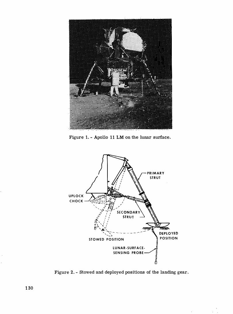
The Apollo 11 LM on the lunar surface is shown in figure 1, which illustrates the overall LM and landing-gear configuration. A landing-gear assembly, in both the stowed and the deployed positions, is shown in figure 2, and the major components are shown in figure 3. Each of the four separate landing-gear assemblies has energyabsorption capability provided by honeycomb cartridges in the single primary and the two secondary struts. The deployment truss serves as a structural-mechanical assembly between the landing-gear struts and the descent-stage structure. Each landinggear leg is retained in the stowed position by a pyrotechnic up lock device. When the device is fired, a titanium strap that is attached to the primary strut and the descent stage is severed, which allows the landing gear to be deployed and locked by mechanisms on each side of the landing-gear assembly.
The primary strut (fig. 4), which is attached to the LM descent-stage outrigger assembly, consists of a lower inner cylinder that fits into an upper outer cylinder to provide compression stroking at touchdown. The footpad, which is attached to the lower end of the inner cylinder by a ball-joint fitting, is approximately 0. 9 1 meter
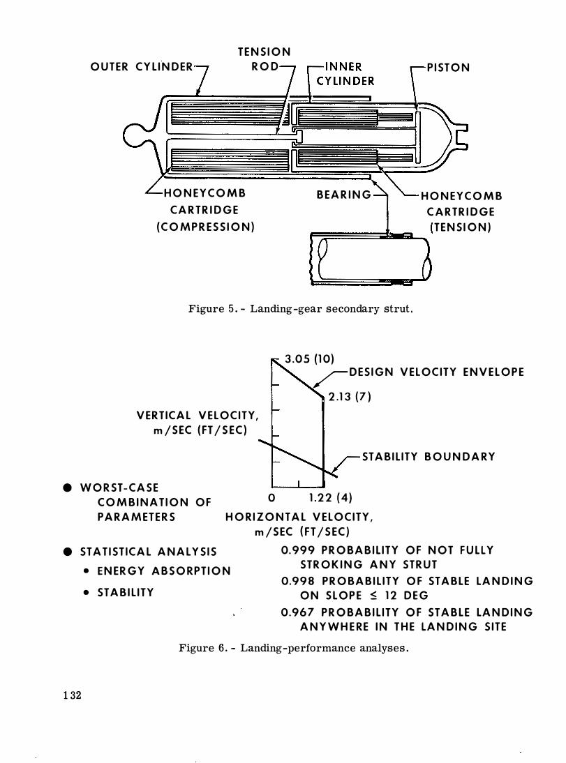
(3 feet) in diameter and is designed to support the LM on a 0. 69 N/cm2 ( 1. 0 lb/in2) bearing-strength surface as well as to maintain sliding capability after having impacted rocks or ledges during touchdown. Attached to each of three of the footpads is a 1. 73-meter (68 inch) probe designed to sense lunar-surface proximity and to signal the LM pilot so that he can initiate descent-engine shutdown. The secondary struts (fig. 5) also have an inner and an outer cylinder and are capable of both tension and compression stroking. Detailed descriptions of the landing gear may be found in references 1 and 2.
LANDING-GEAR DEVELOPMENT PROBLEMS
Statistical Landing Performance
A major change in the treatment of the landing-performance input parameters occurred as a result of the descent-engine thrust-decay time history. For design purposes, a thrust-decay time of approximately 0. 5 second had been assumed. However, a thrust decay of several seconds, which was an extremely destabilizing influence at touchdown, was evident in the actual descent-engine firing data. When the actual thrust-decay time history was combined in a worst-case way with other touchdown parameters, the LM toppling-stability boundary lay well within the design velocity envelope, as illustrated in figure 6. For acceptable stability within the range of touchdown velocities considered, this boundary must lie outside the design envelope. Attempts to reduce the engine thrust-decay time by hardware changes were unsuccessful; therefore, the manner in which the touchdown parameters were combined for design was investigated as a potential solution.
Investigation of the touchdown parameters from piloted simulations revealed that the initial conditions at touchdown did not combine in a worst-case fashion. Furthermore, sufficient data were available to treat the data statistically. Another parameter
124
that affects touchdown performance significantiy is the lunar -surface topography. To make the analysis as realistic as possible, a statistical description of the lunar surface, which consisted of general surface slopes and surface protuberances and depressions, was derived from Lunar Orbiter photography. Descriptions of potential Apollo landing sites were formulated, and the most severe site, based on general surface slope, was chosen for the analysis. The results of the analysis, which are shown in figure 6, indicate the degree of risk involved at touchdown. The analysis showed that the chances of fully stroking any strut was only one in a thousand and that the probability of an unstable landing on slopes of 12° or less was two in a thousand landings. The probability of an unstable landing, when considering all slopes in the landing site, was somewhat higher but was still acceptable. Although these probabilities are based on a Monte Carlo statistical analysis, considerable conservatism is involved. The stability analysis is based entirely on constrained-footpad-type landings; that is, footpad sliding is not considered in calculating toppling stability. For the calculations of stroking, the energy -absorption characteristics of the lunar soil are not considered except for
·
friction as a result of footpad sliding. Furthermore, the statistical.surface description is based on the Apollo site that has the most severe topography of the Apollo landing sites originally considered. Finally, no crew selectivity was assumed to be involved in choosing the touchdown point within the landing site. Actual landings on the lunar surface have verified the conservatism involved. All landings have resulted in footpad sliding, the lunar soil absorbed a large percentage of the impact energy, and the LM crews have been able to use some judgment in choosing a landing site in spite of the dust encountered before touchdown. This analysis, which was used to certify the adequacy of the LM landing performance, constituted a criterion change because of the method of combining design parameters.
Thermal Insulation
Landing-gear thermal insulation must maintain the landing-gear temperatures at or below design levels to ensure positive structural margins of safety and proper mechanical operation during deployment and landing. Furthermore, temperature control of the honeycomb energy absorbers within specified limits is necessary to preclude large variations in crush-load levels. A summary of the history of the landing-gear thermal-insulation weights is provided in table II.
A significant thermal-design problem was caused by the effects of descent-engineplume heating near the lunar surface. A few months before Apollo 11, test data indicated that heating rates on the landing gear were much higher than anticipated. At approximately the same time, the LM flight crew expressed a desire to have the option of using either the probe mode or the pad mode for landing. The probe mode is the primary procedure for LM touchdown and consists of descent-engine shutdown initiation after probe contact with the lunar surface but before footpad contact. The pad mode is considered a backup landing mode in which engine thrust is terminated after footpad contact. Inclusion of the pad mode resulted in even higher predicted heating rates for the landing gear. Consequently, the Apollo 11 landing -gear thermal-insulation weight was increased to 31. 03 kilograms (68. 4 pounds), as shown in table II. A refined analysis allowed reduction of the landing-gear-insulation weight on subsequent vehicles so that it represents approximately 8 percent of the total landing-gear weight. This particular problem illustrates a hardware change made as a result of improved test data and a change in operational procedures.
125

Primary-Strut-Bearing Design
An important design detail in the landing gear is that of the primary strut bearings (fig. 4). The bearing friction must be maintained within close tolerances because it accounts for 10 to 20 percent of the total force in the strut, thereby affecting both structural loads and landing performance. The friction depends on the hearing shape and the clearances, which are temperature dependent. Many component and gearassembly tests were conducted to optimize the bearing friction. The effects of configuration on the effective coefficient of friction, which varies from approximately 0. 05 on a flat surface to approximately 0. 21 as the effective value based on the side load at the footpad, are illustrated in figure 7. BecausE? footpad side load determines the bearing normal load, it is important to base the friction on the footpad load as well as to realize that the effective coefficient differs considerably from the actual coeffi cient based on normal force at the bearing. Additionally, thermal analysis must ensure that a positive clearance always exists between the bearing and the strut, thereby eliminating the possibility of very large axial loads as a result of binding. This development problem illustrates the importance of attention to detail in the landing-gear mechanical design.
FLIGHT-PERFORMANCE RESULTS
Before the Apollo 11 mission, LM landing performance and landing-gear functional operation had been demonstrated by analysis and by extensive ground tests. During these tests, the landing gear was exposed to all significant flight environments, including vehicle drop tests under simulated lunar- gravity conditions. Landing-gear deployment has been successfully accomplished on eight Apollo missions. Of the five lunar landings attempted, all were successful. The landing- gear touchdownperformance results may be summarized by considering two of the pertinent parameters, surface slope at the touchdown point and touchdown velocities, which are summarized in figure 8. In all cases, the touchdown velocities were within design limits. The actual slopes at the touchdown point are compared with the landing- site slope statistics used in the touchdown analysiso The slope curves may be interpreted by choosing a particular slope (for example, 11 o, the Apollo 15 touchdown slope at Hadley-Apennine) and reading the corresponding value of approximately 95 percent on the ordinate. This states that 95 percent of the slopes at this landing site are 11 o or less. For all landings, vehicle attitudes and angular rates during touchdown have been low, indicating very stable landings.
Gear stroking in all landings has been minimal. The lunar soil has absorbed an estimated 60 percent of the touchdown energy through footpad penetration and sliding, resulting in secondary- strut tension stroking of about 10 centimeters (4 inches). A small amount of primary- strut stroking has occurred in some instances.
126

CONCLUDING REMARKS
Problems encountered during the development of the LM landing gear have been solved, and at no time did the availability of landing-gear hardware jeopardize the Apollo Program schedule. The problems were solved by various means, some by hardware changes and some by criteria changes when such changes had a rational basis. It is concluded that the landing gear met the Apollo design requirements and that development problems were solved before flight.
REFERENCES
1. Hilderman, R. A.; Mueller, W. H. ; and Mantus, M.: Lunar Module Alightment System. Aerospace Mechanisms, vol. 1, part A, G. Herzl, ed. , Lockheed Missiles and Space Corp., 1970, pp. 201-210.
2. Rogers, W. F. : Apollo Experience Report - Lunar Module Landing Gear Subsystem. NASA TN D-6850, 1972.
DISCUSSION
J. T. Hinricks: Ultimately, what material was selected for primary-strut bearings?
Rogers: The primary-strut bearings are made of aluminum and are coated with a moly
disulfide dry-film lubricant.
127
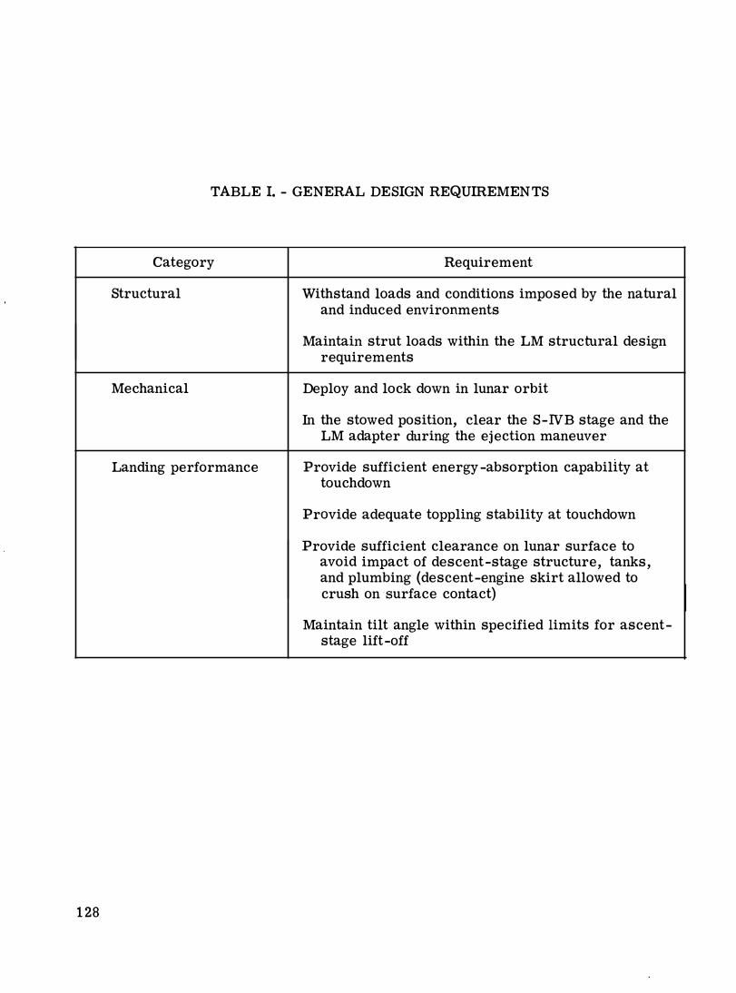
TABLE I. - GENERAL DESIGN REQUIREMENTS
Category Requirement
Structural Withstand loads and conditions imposed by the natural and induced environments
Maintain strut loads within the LM structural design requirements
Mechanical Deploy and lock down in lunar orbit
In the stowed position, clear the S-NB stage and the LM adapter during the ejection maneuver
Landing performance Provide sufficient energy -absorption capability at touchdown
Provide adequate toppling stability at touchdown
Provide sufficient clearance on lunar surface to avoid impact of descent-stage structure, tanks, and plumbing (descent-engine skirt allowed to crush on surface contact)
Maintain tilt angle within specified limits for ascent-stage lift-off
128
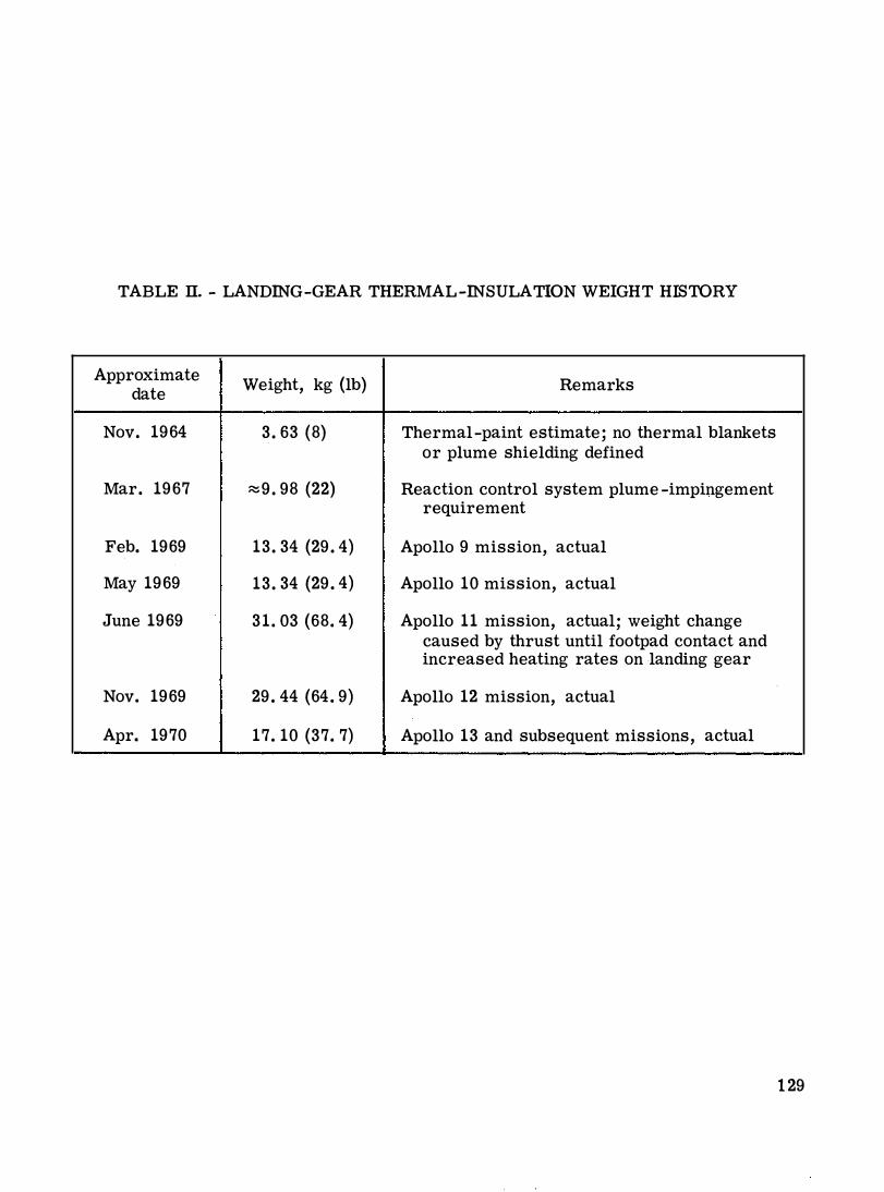
TABLE II. - LANDING-GEAR THERMAL-INSULATION WEIGHT HISTORY
Approximate Weight, kg (lb} Remarks
date
Nov. 1964 3. 63 (8} Thermal-paint estimate; no thermal blankets or plume shielding defined
Mar. 1967 :::::9. 98 (22} Reaction control system plume -impingement requirement
Feb. 1969 13. 34 (29. 4) Apollo 9 mission, actual
May 1969 13. 34 (29. 4) Apollo 10 mission, actual
June 1969 31. 03 (68. 4) Apollo 11 mission, actual; weight change caused by thrust until footpad contact and increased heating rates on landing gear
Nov. 1969 29. 44 (64. 9) Apollo 12 mission, actual
Apr. 1970 17. 10 (37. 7) Apollo 13 and subsequent missions, actual
129
130
Figure 1. - Apollo 11 LM on the lunar surface.
UPLOCK CHOCK
STOWED POSITION
LUNAR-SURFACESENSING PROBE
PRIMARY STRUT
POSITION
Figure 2.- Stowed and deployed positions of the landing gear.

DEPLOYMENT
AND DOWNLOCK
DEPLOYMENT
TRUSS
SIDE BRACE
DEPLOYMENT
TRUSS
LUNAR-SURFACE
SENSING PROBE
SECONDARY STRUT
PRIMARY STRUT
Figure 3. - The LM landing gear.
INNER CYLINDER
42 2 56 N
(9 500 LB)
HONEYCOMB
CARTRIDGE
LOWER BEARING
SEPARATION
PLATE
HONEYCOMB
CARTRIDGE
Figure 4.- Landing-gear primary strut.
131
OUTER CYLINDER
TENSION
ROD
HONEYCOMB
CARTRIDGE
(COMPRESSION)
BEARING
PISTON
HONEYCOMB
CARTRIDGE
R���.t..lliiL_( TENS I 0 N)
Figure 5. - Landing-gear secondary strut.
VERTICAL VELOCITY,
m /SEC (FT /SEC)
3.05 {10) /DESIGN VELOCITY ENVELOPE
2.13 (7)
STABILITY BOUNDARY
e WORST-CASE
COMBINATION OF
PARAMETERS
0 1.22 (4)
H 0 R I Z 0 NT A L VEL 0 CITY,
m/SEC (FT /SEC)
e STATISTICAL ANALYSIS
• ENERGY ABSORPTION
• STABILITY
0.999 PROBABILITY OF NOT FULLY
STROKING ANY STRUT
0.998 PROBABILITY OF STABLE LANDING
ON SLOPE � 12 DEG
0.967 PROBABILITY OF STABLE LANDING
ANYWHERE IN THE LANDING SITE
Figure 6. - Landing-performance analyses.
132

CONFIGURATION p AVG
i t t t !
TEMPERATURE
I I !-D-1
c �� N l-x-1--x-l Np
F = 1£N, I' � 0.05 N = p AVGD
N = 1.4 p AVG D
F = 1.4 1£P AVGD
�'EFF = 1.41£ = 0.07
F = 1.4 I' (3N) = 0.07 {3N) = 0.21 N
•• ·I'EFF = 0.21
Figure 7. - Strut-bearing friction.
VERTICAL VELOCITY,
m/SEC
3.05 (10)
2.13 (7)
(FT /SEC) . 1.22 (4)
r SPECIFICATION TOUCHDOWN VElOCITY ENVELOPE
APOLLO 15
APOLLO 12 APOLLO 14 APOLLO ll
0 1.22 (4) HORIZONTAL VElOCITY, m/SEC (FT /SEC)
PERCENT OF 60
SLOPES 40 LESS THAN
20
0
APOLLO 15 FRA MAURO
4
/ HADLEY-APENNINE ��=:::::::::=-
8
'--WORST OF SEVEN ORIGINAL
12
APOLLO SITES; USED TO CERTIFY LM TOUCHDOWN
PERFORMANCE
16 20 24
TOUCHDOWN SLOPE, DEG
Figure 8. - The LM flight-performance results.
133