apollo iv pentium pci isa motherboardguide apollo iv pci pentium isa motherboard user’s guide...
TRANSCRIPT

Apollo IV Pentium
PCI ISA MotherboardGuide
MAN-77211/21/97

Apollo IV PCI Pentium ISA Motherboard User’s Guideii
© Copyright 1985-2010 American Megatrends, Inc.All rights reserved.American Megatrends, Inc.5555 Oakbrook Parkway, Building 200,Norcross, GA 30093
This publication contains proprietary information which is protected by copyright. No part of this publication may be reproduced, transcribed,stored in a retrieval system, translated into any language or computer language, or transmitted in any form whatsoever without the prior writtenconsent of the publisher, American Megatrends, Inc.
Limited Warranty
Buyer agrees if this product proves to be defective, that American Megatrends, Inc. is only obligated to replace or refund the purchase price ofthis product at American Megatrends’ discretion according to the terms and conditions on the motherboard warranty card. American Megatrendsshall not be liable in tort or contract for any loss or damage, direct, incidental or consequential. Please see the Warranty Registration Cardshipped with this product for full warranty details.
Limitations of Liability
In no event shall American Megatrends be held liable for any loss, expenses, or damages of any kind whatsoever, whether direct, indirect,incidental, or consequential, arising from the design or use of this product or the support materials provided with the product.
Trademarks
Intel and Pentium are registered trademarks of Intel Corporation.MS-DOS, Microsoft Word, and Microsoft are registered trademarks of Microsoft Corporation. Microsoft Windows 95 and Windows NT aretrademarks of Microsoft Corporation.IBM, AT, VGA, PS/2, OS/2, and EGA are registered trademarks of International Business Machines Corporation. XT and CGA are trademarksof International Business Machines Corporation.Fujitsu is a registered trademark of Fujitsu America, Inc.Motorola is a registered trademark of Motorola Corporation.Hitachi is a registered trademark of Hitachi America, Ltd.NEC is a registered trademark of NEC Corporation.Samsung is a registered trademark of Samsung Electronics Corporation.Siemens is a trademark of Siemens Corporation.Mitsubishi is a registered trademark of Mitsubishi Electronics of America.Micron is a registered trademark of Micron Corporation.SCO, UnixWare, and Unix are registered trademarks of The Santa Cruz Operation, Inc.Toshiba is a registered trademark of Kabushiki Kaisha Toshiba.VESA is a trademark of the Video Electronics Standards Association.All other brand and product names are trademarks or registered trademarks of their respective companies.
Revision History
11/21/97 Initial release.

Preface iii
Preface
To the OEM Thank you for purchasing the high performance American MegatrendsApollo IV PCI Pentium ISA motherboard. This product is a state of the artmotherboard that includes the famous AMIBIOS. It is assumed that you havealso licensed the rights to use the American Megatrends documentation forthe American Megatrends Apollo IV motherboard
This manual was written for the OEM to assist in the proper installation andoperation of this motherboard. This manual describes the specifications andfeatures of the Apollo IV motherboard. It explains how to assemble a systembased on the Apollo IV motherboard and how to use the AMIBIOS that isspecifically designed for this motherboard.
This manual is not meant to be read by the computer owner who purchases acomputer with this motherboard. It is assumed that you, the computermanufacturer, will use this manual as a sourcebook of information, and thatparts of this manual will be included in the computer owner's manual.
Technical Support
If you need help installing, configuring, or running this product, callAmerican Megatrends technical support at 770-246-8645. You can also sendquestions to tech support at:
American Megatrends BBS The American Megatrends BBS permits you to access technicalinformation about American Megatrends motherboard, peripheral, and BIOSproducts. Product Engineering Change Notices, Tech Tips, and technicaldocumentation are available on the BBS. Some parts of the BBS are notaccessible to all callers. Call American Megatrends Technical Support at 770-246-8645 to find out how to access the BBS.
Phone Numbers The BBS requires no parity, eight data bits, and one stop bit. Thecharacteristics of the BBS phone numbers are:
Phone Number Characteristics770-246-8780 28,800 baud rate. Supports v.34.770-246-8781 28,800 baud rate. Supports v.34.770-246-8782 Supports HST and v.42.770-246-8783 Supports HST and v.42.
Web Site We invite you to access the American Megatrends world wide web site at:
http://www.ami.com.

Apollo IV PCI Pentium ISA Motherboard User’s Guideiv
Packing List
You should have received the following:
• an Apollo IV Pentium PCI ISA motherboard,• a diskette containing the DMI Wizard 95 utility,• the American Megatrends DMI Wizard 95 User’s Guide,• an optional USB cable and mounting bracket,• two serial cables,• one parallel cable,• a Warranty Card, and• the American Megatrends Apollo IV Pentium ISA Motherboard User's Guide.
WarningThe pinout for the optional USB Cable Box is:
Pin 1 Red VCCPin 2 Green Data +Pin 3 White Data -Pin 4 Black GroundPlease make sure that the USB cable is correctly installed. Incorrect
installation will damage the motherboard.
Static Electricity
The Apollo IV motherboard can easily be damaged by static electricity. Makesure you take appropriate precautions against static electric discharge:
• wear a properly-grounded wristband while handling the motherboard or any otherelectrical component,
• touch a grounded anti-static surface or a grounded metal fixture before handlingthe Apollo IV motherboard,
• handle system components by the mounting bracket, if possible.
Batteries Make sure you dispose of used batteries according to the batterymanufacturer’s instructions. Improper use of batteries may cause anexplosion. Make sure you follow the battery manufacturer’s instructions aboutusing the battery. Replace used batteries with the same type of battery or anequivalent recommended by the battery manufacturer.

Chapter 1 Hardware Installation 1
1 Hardware InstallationOverview
The American Megatrends Apollo IV PCI Pentium ISA motherboard includesthe following features.
CPU The CPU socket on the motherboard is a 321-pin ZIF socket. A switchingvoltage regulator is required. You can install any of the following CPUs:
CPU Manufacturer Supported CPU SpeedsIntel® Pentium P55C 166, 200, and 233 MHz
Intel Pentium P54C withMMX™ technology
90, 100, 120, 133, 150, 166, and 200MHz
AMD® K6-166 166 MHzAMD K6-200 200 MHzAMD K6-233 233 MHz
AMD K5-PR90 90 MHzAMD K5-PR100 100 MHzAMD K5-PR120 90 MHzAMD K5-PR133 100 MHzAMD K5-PR150 105 MHzAMD K5-PR166 116 MHzAMD K5-PR200 133 MHz
MMX Technology This motherboard supports CPUs that include support for Intel MMXtechnology. MMX technology allows you to experience richer video, audio,digital imaging and communications when running the latest generation ofmultimedia software on your computer.
Cont’d

Apollo IV PCI Pentium ISA Motherboard User’s Guide2
Overview, Continued
Chipset The Apollo IV PCI Pentium ISA baby-AT size motherboard uses an Intel430TX chipset, including CPU interface controller, advanced cachecontroller, integrated DRAM controller, synchronous ISA bus controller, PCIlocal bus interface, and an integrated power management unit. The Intel430TX chipset supports intelligent diagnostic and power managementthrough features such as DMI support.
Expansion Slots The motherboard includes:
• three 16-bit ISA expansion slots and• four 32-bit PCI expansion slots.The PCI local bus throughput can be up to 132 megabytes per second.
L1 Internal Cache The Intel Pentium on the motherboard has an 8 KB data cache and an 8KB instruction cache.
L2 Secondary Cache The motherboard has 512 KB of pipeline burst direct-mapped,WriteBack L2 secondary cache memory. Up to 256 MB of system memorycan be cached.
Supported Standards The Apollo IV motherboard supports:
• DMI,• the Intel DPMA (Dynamic Power Management Architecture,• Concurrent PCI V2.0 and V2.1, and• USB (Universal Serial Bus).
Switching Voltage Regulator This motherboard includes a switching voltage regulator thatsignificantly reduces the CPU and voltage regulator temperature. This voltageregulator is also fully upgradable to the next generation of Socket 7 CPUs.These new CPUs will require more electrical current and will generate moreheat.
Cont‘d

Chapter 1 Hardware Installation 3
Overview, Continued
CPU Thermal Monitor The Apollo IV motherboard includes a special heat sensor under theCPU that monitors the CPU temperature. This heat sensor generates an SMI(System Management Interrupt) when the CPU temperature is too hot. TheSMI can be set to turn on the external cooling fan and/or lower the CPU clockfrequency. You are waned that the CPU is overheating. The CPU is returnedto normal operating conditions when the CPU temperature returns to normal.This feature can only be implemented if a power supply with a soft-off powercontroller is installed in the computer. See the American Megatrends DMIWizard 95 User’s Guide for additional information about this feature.
SDRAM The Apollo IV motherboard provides two 168-pin DIMM system memorysockets that support SDRAM (Synchronous Dynamic Random AccessMemory). SDRAM increases the CPU-to-memory data transfer rate to 528MBs. This rate is normally 264 MBs if EDO DRAM is installed. Theintegrated I2C controller optimizes the memory timing parameters.
System Memory The motherboard supports up to 256 MB of system memory mounted on themotherboard as follows:
Type of SystemMemory Socket
Type of SystemMemory
Supported SystemMemory
four 72-pin SIMMsockets
Fast Page Mode orEDO DRAM
8 MB, 16 MB, 32 MB,64 MB, or 128 MB
two 168-pin DIMMsockets
EDO DRAM orSDRAM
8 MB, 16 MB, 32 MB,64 MB, or 128 MB
Cont’d

Apollo IV PCI Pentium ISA Motherboard User’s Guide4
Overview, Continued
PC 97 Compliant The Apollo IV motherboard is fully compliant with the Microsoft PC 97specification at both the hardware and the BIOS levels.
PC 97 is a set of hardware, bus, and device design requirements specified byMicrosoft that make computers easier to use. PC 97 supports cooperationbetween the operating system, the hardware, and the applications software.Key PC 97 features include:
• Plug and Play compatibility,• power management support for configuring and managing all system
components• 32-bit device drivers, and• standard installation procedures for Microsoft Windows 95 and Windows
NT.
AMIBIOS Features This motherboard has an AMIBIOS system BIOS on a Flash ROM withbuilt-in AMIBIOS Setup. AMIBIOS features include:
• IDE block mode and 32-bit data transfer support,• IDE Programmed I/O modes 0, 1, 2, 3, and 4 support,• PS/2 mouse support,• IDE LBA mode support,• APM (Advanced Power Management) and Flash BIOS hooks,• EPA Green PC-compliant,• PCI and Plug and Play (PnP) support, and• DIM (Device Initialization Manager) support,• DMI (Desktop Management Interface) support,• can boot from a CD-ROM drive,• automatically detects system memory, cache memory, and hard disk drive
parameters,• Intel NSP-compliant,• Fast ATA IDE mode programming and ATAPI support,• Boot sector virus protection,• instant-on support,• automatically configures PnP and PCI devices.
Cont’d
Chapter 1 Hardware Installation 5
Overview, Continued
BIOS Shadowing The system BIOS is always copied from ROM to RAM for faster execution.The end user can shadow 16 KB ROM segments from C0000h – DCFFFh.
IDE The Apollo IV motherboard has two 40-pin IDE connectors onboard thatsupport up to four IDE drives (hard disk drives, CD-ROM drives, or tapedrives). The integrated PCI bus master enhanced IDE controller is on the PCIlocal bus. The IDE controller supports the Ultra DMA/33 protocol, whichdoubles the hard disk drive data transfer rates specified in the ATA-2standards to 33 MBs while maintaining full backward compatibility withexisting PIO mode 3, PIO mode 4, and DMA mode 2 devices.
Fast ATA The motherboard supports the Fast ATA specification using PIO mode 4 andmultiword DMA mode 2.
Ultra DMA/33 This motherboard includes an integrated enhanced IDE PCI bus master IDEcontroller that supports the Ultra DMA/33 protocol. The Ultra DMA/33protocol permits data transfer rates up to 33 MBs. Ultra DMA/33 also reducesthe CPU workload and permits increased CPU utilization. Ultra DMA/33 iscompletely backward-compatible with older DMA standards.
Floppy The Apollo IV motherboard has an onboard floppy controller that supports upto two 360 KB, 720 KB, 1.2 MB, 1.44 MB, or 2.88 MB floppy drives.
Parallel Port The Apollo IV motherboard has an onboard ECP and EPP-capable parallelport connector.
Serial Ports The Apollo IV motherboard has two onboard serial port connectors and two16550 UART serial ports.
Keyboard The Apollo IV motherboard Includes a standard DIN keyboard connector.
Cont’d

Apollo IV PCI Pentium ISA Motherboard User’s Guide6
Overview, Continued
Mouse The Apollo IV motherboard includes a 5-pin berg mouse connector.
USB The Apollo IV motherboard has two 4-pin USB connectors. USB allowsfuture generations of USB-compliant peripheral devices to be automaticallydetected and configured through a single port. USB uses Plug and Playtechnology. All USB peripherals are automatically detected and configured.The AMIBIOS on this motherboard provides complete USB system BIOSsupport.
Power Connectors The Apollo IV motherboard has three power supply connectors.
RTC/CMOS RAM A real time clock and 128 bytes of CMOS RAM with a battery backup isprovided on the motherboard.
Power Management Power management services include:
• Green PC LED,• power management signal to Green PC-aware power supplies,• automatic IDE and video power down,• monitor blanking,• SMI (System Management Interrupt) support,• APM, and• system stop clock.
PCI Slots The motherboard conforms to the PCI Version 2.1 specification. Theconcurrent PCI architecture of this motherboard allows faster CPU, PCI, andISA bus transactions for faster and smoother multimedia performance. Thismotherboard allows you to install either PCI V2.0 or PCI V2.1-comaptibleadapter cards
The PCI slots are automatically configured by the AMIBIOS. The PCI slotsoperate synchronously with the CPU clock, as follows:
CPU External Clock Frequency PCI Expansion Slot Frequency66 MHz 33 MHz60 MHz 30 MHz
Onboard I/O The Apollo IV Pentium ISA motherboard includes:
• two 40-pin IDE connectors on the PCI bus that support up to four IDEdrives,
• a 34-pin floppy drive connector,• two 10-pin serial port connectors (with 16550 UARTs),• a 26-pin parallel port connector with ECP and EPP support,• an infrared connector,• two USB connectors that support an optional riser card that permit high
speed Plug and Play connection to USB-compliant external peripheraldevices,
• a keyboard connector, and• a PS/2 mouse connector.
Cont’d

Chapter 1 Hardware Installation 7
Overview, Continued
DMI In a corporate environment, system manageability is an importantconsideration. DMI (Desktop Management Interface) is a specification for astandard method of storing and reporting system information. Thismotherboard supports the DMI specification on the system BIOS level. DMIdetects and records system configuration information, including the CPU typeand speed, memory size and type, and much more information. DMImaintains a local database of system configuration information that can beaccessed and even modified from a remote location.
The American Megatrends DMI Wizard 95 is also shipped with thismotherboard. Use DMI Wizard 95 to display and modify DMI information.DMI Wizard 95 allows a system integrator or user to add additionalinformation to the DMI database, such as serial numbers and chassisinformation. See the American Megatrends DMI Wizard 95 User’s Guide foradditional information.
Infrared This motherboard includes a 10-pin serial infrared connector. Infrared allowsbidirectional cordless data transactions with other IrDA-compliant computersand peripheral devices. Infrared transmissions can occur in half-duplex(sequential transmission/receiving) or full-duplex (simultaneoustransmission) modes.
A 10-pin infrared connector is provided on the motherboard. Themotherboard and AMIBIOS comply with the IrDA SIR infrared devicestandards and specifications.
This motherboard complies fully with the IrDA infrared standards. An IrDA-compliant device can be installed via a 9-pin D-type connector on the rear ofthe computer. The 9-pin connector is attached by a cable to the IR bergconnector on the motherboard, next to the serial connectors (COM1 andCOM2). COM2 on the motherboard is an IrDA-compliant port. You must setthe Serial Port2 Mode, IR Transmission Type, and other AMIBIOS Setupoptions under Peripheral Setup before you can use an infrared device.

Apollo IV PCI Pentium ISA Motherboard User’s Guide8
Apollo IV Dimensions
Motherboard Size The Apollo IV Pentium PCI ISA motherboard is the standard baby AT size(11” by 8.6”).
Motherboard Height Restrictions

Chapter 1 Hardware Installation 9
Installation Steps
Step Action1 Unpack the motherboard.2 Set Jumpers3 Configure the CPU.
Select the CPU voltage.Select the CPU speed.Install the CPU.
4 Install memory.Install system memory.
5 Install the motherboard.6 Attach cables to connectors.
Connect the power supply.Attach the keyboard cable.Connect the mouse cable.Attach cables.
7 Connect onboard I/O.Connect the serial ports.Connect the parallel port.
8 Connect floppy drive(s).9 Connect the IDE drive(s).10 Test and configure.
WarningThis motherboard contains sensitive electronic componentsthat can be easily damaged by static electricity. Follow theinstructions carefully to ensure correct installation and to
avoid static damage.
Apollo IV PCI Pentium ISA Motherboard User’s Guide10
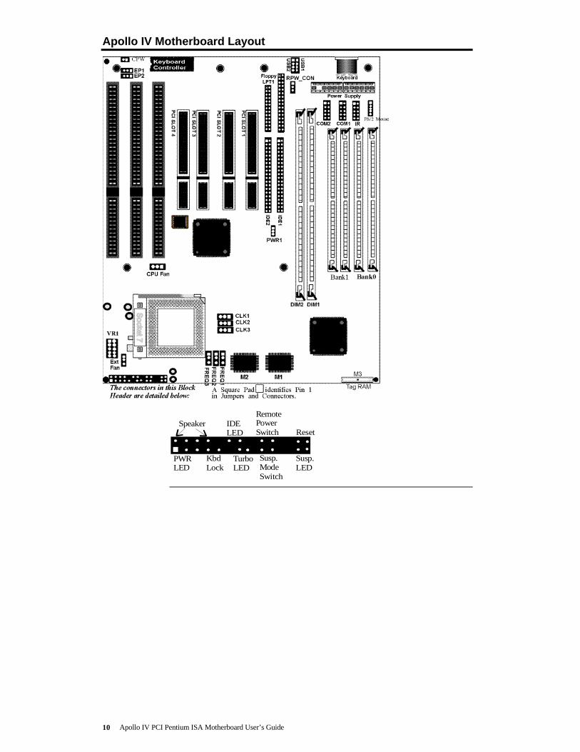
Apollo IV Motherboard Layout
Speaker IDELED
PWRLED
KbdLock
Reset
Susp.ModeSwitch
TurboLED
Susp.LED
RemotePowerSwitch

Chapter 1 Hardware Installation 11
Step 1 Unpack the Motherboard
Step Action
1 Inspect the cardboard carton for obvious damage. If damaged, call 770-246-8645. Leave the motherboard in its original packing.
2 Perform all unpacking and installation procedures on a ground-connectedanti-static mat. Wear an anti-static wristband grounded at the same pointas the anti-static mat. Or use a sheet of conductive aluminum foilgrounded through a 1 megohm resistor instead of the anti-static mat.Similarly, a strip of conductive aluminum foil wrapped around the wristand grounded through a 1 megohm resistor serves the same purpose as thewristband.
3 Inside the carton, the motherboard is packed in an anti-static bag, andsandwiched between sheets of sponge. Remove the sponge and theanti-static bag. Place the motherboard on a grounded anti-static surfacecomponent side up. Save the original packing material.
4 Inspect the motherboard for damage. Press down on all ICs mounted insockets to verify proper seating. Do not apply power to the motherboard ifit has been damaged.
5 If the motherboard is undamaged, it is ready to be installed.

Apollo IV PCI Pentium ISA Motherboard User’s Guide12
Step 2 Set Jumpers
Set all jumpers and install the CPU before placing the motherboard in thechassis. Set jumpers by placing a shunt (shorting bridge) on the designatedpins of the jumper. A shunt and jumpers are shown below:
Shunt 3-pin Berg 2-pin Berg
In this manual, jumpers are shown in two -dimensions,as if viewed from directly above, as shown below:
1
3
5
2
4
6
The placement of shunts isindicated by a solid linebetween pins, as shownbetween Pins 1-2to the right:
1
3
5
2
4
6
3-dimensional view of motherboard jumpers and a shunt.
PWR1 Power Supply Type PWR1 is a 3-pin berg that sets the power supply type:
PWR1 Setting DescriptionShort Pins 1-2 AT-type power supply is installed (factory setting).Short Pins 2-3 Remote power supply is used.
CPW Clear Password CPW is a 2-pin berg that allows you to delete the system BIOSpassword should you forget the password. CPW should be OPEN at all timesduring normal operation. Should you forget the password: turn power off,remove the computer cover, turn power on, place a shorting bridge (shunt) onCPW for a few seconds, then turn power off again. Reboot the computer andre-enter all system configuration information, because you have just erased allof it.
Cont’d

Chapter 1 Hardware Installation 13
Step 2 Set Jumpers, Continued
EP1, EP2 Flash ROM Type EP1 and EP2 are 3-pin bergs that specify the type of flash ROMinstalled on the motherboard. The settings are:
Flash ROM Type EP1 EP2Intel 28F001 Short Pins 2-3 Short Pins 1-2
SST 29EE010 OPEN Short Pins 2-3MXIC MX28F2000 Short Pins 2-3 Short Pins 2-3
SST 29EE020 OPEN Short Pins 2-3ATMEL AT29C020 OPEN Short Pins 2-3
AMD 28F020 Short Pins 1-2 Short Pins 2-3
Avoid Static Electricity
Static electricity can damage the motherboard and other computercomponents. Keep the motherboard in the anti-static bag until it is to beinstalled. Wear an anti-static wrist grounding strap before handling themotherboard. Make sure you stand on an anti-static mat when handling themotherboard.
Avoid contact with any component or connector on any adapter card, printedcircuit board, or memory module. Handle these components by the mountingbracket.
Apollo IV PCI Pentium ISA Motherboard User’s Guide14
Step 3 Configure CPU
ImportantPerform the following steps to configure the
motherboard before installing a CPU.
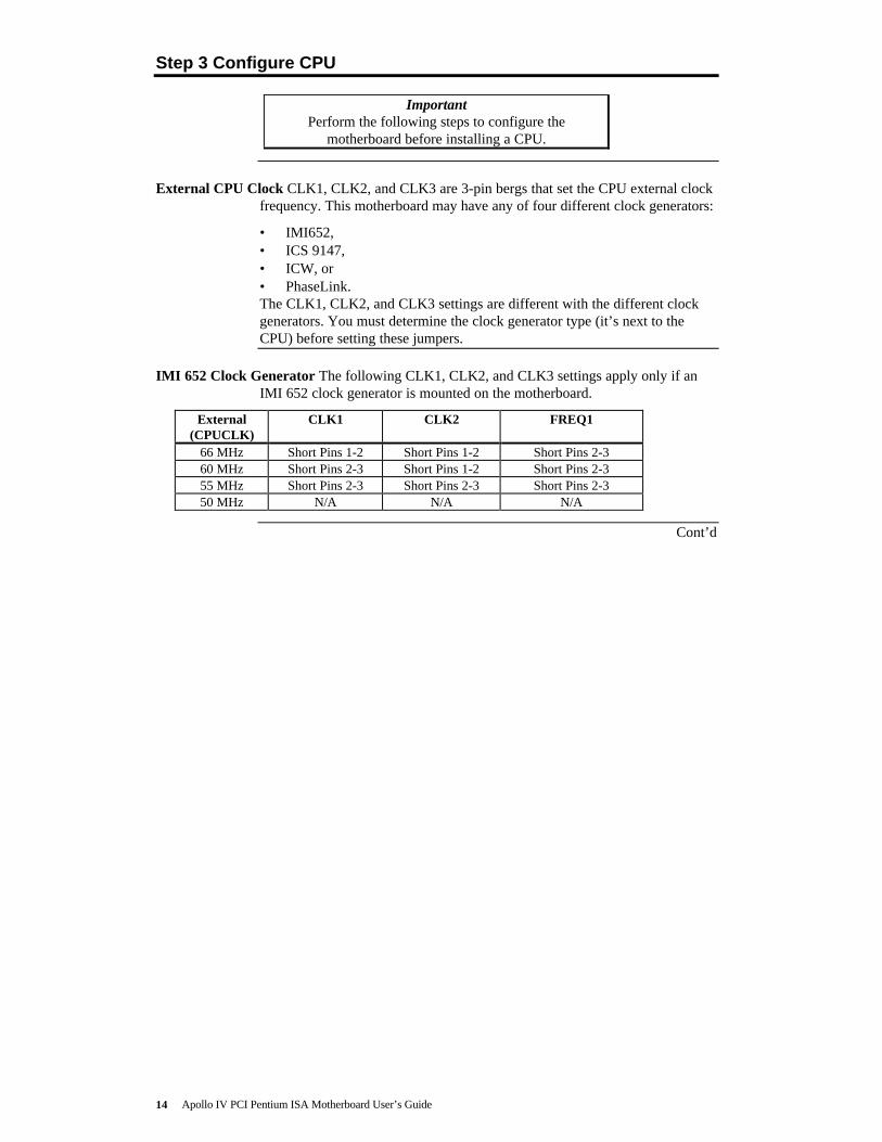
External CPU Clock CLK1, CLK2, and CLK3 are 3-pin bergs that set the CPU external clockfrequency. This motherboard may have any of four different clock generators:
• IMI652,• ICS 9147,• ICW, or• PhaseLink.The CLK1, CLK2, and CLK3 settings are different with the different clockgenerators. You must determine the clock generator type (it’s next to theCPU) before setting these jumpers.
IMI 652 Clock Generator The following CLK1, CLK2, and CLK3 settings apply only if anIMI 652 clock generator is mounted on the motherboard.
External(CPUCLK)
CLK1 CLK2 FREQ1
66 MHz Short Pins 1-2 Short Pins 1-2 Short Pins 2-360 MHz Short Pins 2-3 Short Pins 1-2 Short Pins 2-355 MHz Short Pins 2-3 Short Pins 2-3 Short Pins 2-350 MHz N/A N/A N/A
Cont’d

Chapter 1 Hardware Installation 15
Step 3 Configure CPU, Continued
ICS 9147 Clock Generator The following CLK1, CLK2, and CLK3 settings apply only if anICS 9147 clock generator is mounted on the motherboard.
External(CPUCLK)
CLK1 CLK2 FREQ1
66 6 MHz Short Pins 1-2 Short Pins 2-3 Short Pins 2-360 MHz Short Pins 2-3 Short Pins 2-3 Short Pins 2-355 MHz Short Pins 1-2 Short Pins 1-2 Short Pins 2-350 MHz Short Pins 2-3 Short Pins 1-2 Short Pins 2-3
ICW or PhaseLink Clock Generator The following CLK1, CLK2, and CLK3 settings applyonly if an ICW or PhaseLink clock generator is mounted on the motherboard.
External(CPUCLK)
CLK1 CLK2 FREQ1
66 6 MHz Short Pins 1-2 Short Pins 1-2 Short Pins 1-260 MHz Short Pins 2-3 Short Pins 1-2 Short Pins 1-255 MHz Short Pins 2-3 Short Pins 2-3 Short Pins 1-250 MHz N/A N/A N/A
CPU/Bus Frequency Ratio FREQ1, FREQ2, and FREQ3 are 3-pin bergs that set the ratio ofthe internal CPU frequency to the bus clock.
ForP54C
ForP55C,
and K6
ForK5
FREQ1 FREQ2 FREQ3
3x 3x 2x Short Pins 1-2 Short Pins 2-3 Short Pins 1-22.5x 2.5x 1.75x Short Pins 2-3 Short Pins 2-3 Short Pins 1-22x 2x N/A Short Pins 2-3 Short Pins 1-2 Short Pins 1-2
1.5x 3.5x 1.5x Short Pins 1-2 Short Pins 1-2 Short Pins 1-2
Cont’d

Apollo IV PCI Pentium ISA Motherboard User’s Guide16
Step 3 Configure CPU, Continued
Summary of Jumper Setting for Intel Pentium CPUsMulti Ext. IMI 652 Clock Generator OCS 9147 Clock Generator
Speed plier Speed CLK1 CLK2 CLK3 CLK1 CLK2 CLK3 FREQ1 FREQ2
FREQ3
P55C233 3.5x 66
200 3x 66
166 2.5x 66
P54C200 3x 66
166 2.5x 66
150 2.5x 60
133 2x 66
120 2x 60
100 1.5x 66
90 1.5x 60
Cont’d

Chapter 1 Hardware Installation 17
Step 3 Configure CPU, Continued
Summary of Jumper Setting for AMD K5 and K6 CPUsMult Ext. IMI 652 Clock Generator OCS 9147 Clock Generator
Speed plier Speed CLK1 CLK2 CLK3 CLK1 CLK2 CLK3 FREQ1 FREQ2 FREQ3
K6-233233 3.5x 66
K6-200200 3x 66
K6-166166 2.5x 66
K5-PR200200 2x 66
K5-PR166166 1.75x 66
K5-PR150150 1.75x 60
K5-PR133133 1.5x 66
K5-PR120120 1.5x 60
K5-PR100100 1.5x 66
K5-PR9090 1.5x 60
Cont’d
Apollo IV PCI Pentium ISA Motherboard User’s Guide18
Step 3 Configure CPU, Continued
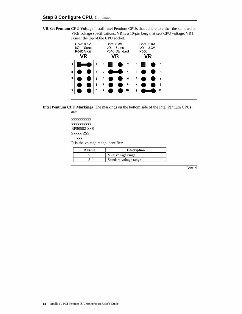
VR Set Pentium CPU Voltage Install Intel Pentium CPUs that adhere to either the standard orVRE voltage specifications. VR is a 10-pin berg that sets CPU voltage. VR1is near the top of the CPU socket.
Intel Pentium CPU Markings The markings on the bottom side of the Intel Pentium CPUsare:
xxxxxxxxxxxxxxxxxxxxBP80502-SSSSxxxx/RSS xxxR is the voltage range identifier:
R value DescriptionV VRE voltage rangeS Standard voltage range
Cont’d

Chapter 1 Hardware Installation 19
Step 3 Configure CPU, Continued
Set AMD CPU Voltage Install AMD K5 and K6 CPUs that adhere to either the standard orVRE voltage specifications. VR is a 10-pin berg that sets CPU voltage. VR1is near the top of the CPU socket.
AMD K5 CPU Markings The markings on the top of the AMD K5 CPUs are:
AMD-K5AMD-K5-PRxxxABQwhere B is the voltage range identifier.
AMD K6 CPU Markings The markings on the top of the AMD K6 CPUs are:
AMD-K6
AMD-K6-xxxA AMD K5 CPU Markings The markings on the top of theAMD K5 CPUs are:
AMD-K5AMD-K5_PRxxxAVQwhere V is the voltage range identifier.
B and Vvalue
Description
N Core 3.1 – 3.3VI/O 3.135 – 3.6V
L Core 2.755 – 3.045VI/O 3.135 – 3.6V
Cont’d

Apollo IV PCI Pentium ISA Motherboard User’s Guide20
Step 3 Configure CPU, Continued
Install CPU Install the CPU in the ZIF (zero insertion force) socket by performing thefollowing steps. The CPU socket is near one edge of the motherboard.
WarningImproper CPU installation can damage the CPU and the
motherboard. You must follow the procedures in this section exactlyas documented. Make sure you wear an antistatic wristband while
installing the CPU. Follow all antistatic procedures.
Step Action1 Lift the lever on the ZIF socket. The empty CPU socket looks like
this.
2 Check for bent pins on the CPU. Gently straighten any bent pinswith pliers. Place the CPU in the middle of the socket. Make surethat pin 1 of the CPU is aligned with pin 1 of the socket. Make sureyou are properly grounded while handling the CPU.
3 Complete installation by lifting the ZIF lever to the other side of thesocket, as shown below.

Chapter 1 Hardware Installation 21
Step 4 Install Memory
System Memory The motherboard has four 72-pin SIMM – Single Inline Memory Module)sockets and two 168-pin DIMM sockets. Memory must be populated one bankat a time. Each bank has two sockets. Each bank must be populated with thesame type of SIMM. If a 16 MB SIMM is installed in the first socket inBank0, then the same type of 16 MB SIMM must be installed in the secondBank0 SIMM socket.
The motherboard supports up to 256 MB of system memory mounted on themotherboard as follows:
Type of System MemorySocket
Type of SystemMemory
Supported System Memory
four 72-pin SIMM sockets Fast Page Mode orEDO DRAM
8 MB, 16 MB, 32 MB, 64 MB, or 128MB
two 168-pin DIMMsockets
EDO DRAM orSDRAM
8 MB, 16 MB, 32 MB, 64 MB, or 128MB
Supported System Memory Configurations
SIMMBank0
SIMMBank1
DIMM1 DIMM2 Total SystemMemory
4 MB and4 MB
8 MB
8 MB 8 MB
8 MB and8 MB
16 MB
16 MB 16 MB
16 MB and16 MB
32 MB
32 MB 32 MB
32 MB and32 MB
64 MB
64 MB 64 MB
64 MB and64 MB
128 MB
64 MB 64 MB 128 MB
64 MB and64 MB
64 MB and64 MB
256 MB
Cont’d

Apollo IV PCI Pentium ISA Motherboard User’s Guide22
Step 4 Install Memory, Continued
Installing SIMMs The motherboard has four x 36 SIMM sockets. These sockets can be filledwith either 1 MB x 36, 4 MB x 36, 8 MB x 36, or 16 MB x 36 SIMMs.
Place the motherboard on an anti-static mat. With the component side of theSIMM facing you, firmly push the SIMM into the socket at an angle, thenpush it up. When properly inserted, the SIMM clicks into place as thelatching pins engage.
Memory Display System memory is reported by AMIBIOS as it boots and again whenthe AMIBIOS System Configuration Screen is displayed just before theoperating system boots. The memory displayed by AMIBIOS on the SystemConfiguration Screen is 384 KB less than the total memory installed.
Chapter 1 Hardware Installation 23
Step 5 Install the Motherboard
The motherboard mounting hole pattern is the same as the mounting holepattern on the standard baby AT motherboard. Standoffs and mountingscrews are not supplied with the motherboard. The chassis manufacturershould supply these parts.
Step Action1 Place the chassis on an anti-static mat. Connect the chassis to ground to avoid
static damage during installation. Connect an alligator clip with a wire lead toany unpainted part of the chassis. Ground the other end of the lead at the samepoint as the mat and the wristband.
2 Rotate the chassis so the front is to the right, and the rear is to the left. The sidefacing you is where the motherboard is mounted. The power supply is mountedat the far end of the chassis.
3 Hold the motherboard, component-side up, with the edge with the SIMMsockets toward you and the edge with the power supply connector away fromyou. The keyboard, mouse, and video connectors should be to the left.
4 Carefully slide the motherboard into the chassis. Make certain the edgeconnectors fit the ports in the rear of the chassis. The motherboard should restlevel with the chassis.
5 Place the mounting screws in the holes provided and tighten them. If necessary,shift the motherboard slightly to align the mounting holes on the motherboardwith the holes on the chassis. See the drawing on the next screen.
Warning
If using metallic screws, make sure you use them only in theplated mounting holes.
If using metallic screws, make sure the head of the screw fitscompletely inside the plated mounting holes.
See the graphic on the following screen.
Cont’d

Apollo IV PCI Pentium ISA Motherboard User’s Guide24
Step 5 Install Motherboard, Continued

Chapter 1 Hardware Installation 25
Step 6 Attach Cables
Connectors The Apollo IV motherboard includes many connectors. Connectioninstructions, illustrations of connectors, and pinouts are:
ConnectorPower supply connectorKeyboard connectorMouse connectorCPU FanChassis FanInfraredRemote Power connectorUSB connectorsSpeakerIDE LEDRemote Power SwitchHardware Reset SwitchPower LED (lit when power is on)Keyboard LockTurbo LED (lit when high speed is active)Suspend Mode SwitchSuspend LED (lit when system in suspend mode)Serial PortParallel portFloppy drive connectorIDE drive connectors
Cable Connector Ends When connecting chassis connectors to the motherboard, make sure toconnect the correct connector end. Most connector wires are color-coded.Match the color of the wires leaving the switch or LED to the same pin on theconnector end. There may be more than one connector with the same color-coded wires. If so, follow the wire to the switch or LED. Pin 1 is indicated bya white line. Pin 1 is always nearest the white line.
3 2 1
Cont’d

Apollo IV PCI Pentium ISA Motherboard User’s Guide26
Step 6 Attach Cables, Continued
Connect Power Supply The power supply should match the physical configuration of thechassis. Make sure that the power switch is Off before assembly.
Before attaching all components, make sure that the proper voltage has beenselected. Power supplies often can run on a wide range of voltages and mustbe set (usually via a switch) to the proper range. Use at least a 300 watt powersupply, which should have built-in filters to suppress radiated emissions.
Power Cables Attach the power supply cables to the power connector on the motherboard.AT-compatible power supplies have one twelve pin connector, as shownbelow.
Cont’d

Chapter 1 Hardware Installation 27
Step 6 Attach Cables, Continued
Connector Keys The keys on the connector must be cut to fit on some power supplies, asshown below.
Power Connector Pinout
Pin Description
1 Power Good (Orange wire) (Not used)
2 VCC (Red wire)
3 +12 Volts (Yellow wire)
4 -12 Volts (Blue wire)
5 Ground (Black wire)
6 Ground (Black wire)
7 Ground (Black wire)
8 Ground (Black wire)
9 -5 Volts (White wire)
10 VCC (Red wire)
11 VCC (Red wire)
12 VCC (Red wire)
Keyboard CableThe keyboard attaches via a PS/2 keyboard connector, labeled AT_KB.
Pin Signal Description
1 Keyboard data
2 N/C
3 Ground
4 VCC
5 Keyboard clock
6 N/C
Cont’d

Apollo IV PCI Pentium ISA Motherboard User’s Guide28
Step 6 Attach Cables, Continued
Mouse Cable Attach the mouse connector cable supplied by American Megatrends to thefive-pin mouse berg connector on the motherboard (labeled MS_CON), asshown below. Attach the standard 9-pin mouse connector at the other end ofthe mouse cable to the mouse connector port on the computer case. Incorrectmouse installation can cause the system to hang.
KeyboardConnector
MouseConnector
Attach 5-pin connector to5-pin mouse berg.
5-pin to 9-pinconverter cable
Motherboard
Mount this connectoron the computer case.
Pin Description1 Mouse Clock2 N/C3 N/C4 Mouse Data5 Ground
Cont’d

Chapter 1 Hardware Installation 29
Step 6 Attach Cables, Continued
When connecting chassis connectors to the motherboard, make sure toconnect the correct connector end. Most connector wires are color-coded.Match the color of the wires leaving the switch or LED to the same pin on theconnector end. There may be more than one connector with the same color-coded wires. If so, follow the wire to the switch or LED. Pin 1 is alwaysindicated on the motherboard.
CPU Fan A three-pin berg labeled FAN attaches to the CPU fan. The FAN connector isnear the CPU end of the ISA expansion slots.
Pin Description1 Ground2 +12V3 Ground
Chassis Fan A three-pin berg labeled EXT_FAN attaches to the chassis cooling fan. TheEXT_FAN connector is near the CPU.
Pin Description1 Ground2 +12V3 Ground
IR Infrared The 8-pin infrared connector (IR) next to the COM1 and COM2 connectorsattaches to an infrared port mounted on the computer chassis. It allows datatransmission to any other device that supports the IrDA standards for infraredtransmission.
Remote Control Power RPW_COM is a 3-pin berg next to the USB connectors that attachesto the power supply for enabling system power when the remote power switchis turned on. Connect a 3-wire power cable to RPW_COM and attach theother end to the peripheral device.
USB Connectors The Apollo IV motherboard has two 4-pin headers (USB1 and USB2) thatattach to a USB connector on the computer chassis. The USB port allows youto attach to a USB hub. The USB connector pinouts are the same for bothUSB connectors:
Pin Signal Description1 VCC (Fused 5V)2 - Data3 + Data4 Ground
Cont’d

Apollo IV PCI Pentium ISA Motherboard User’s Guide30
Step 6 Attach Cables, Continued
Block Connector The Apollo IV motherboard has a 22-pin header that is used to connect thefollowing offboard connectors. The header is on the corner of themotherboard near the CPU socket.
Pins 12 13 14 15 16 17 18 19 20 21
1 2 3 4 5 6 7 8 9 10 11Pins
Connector Signal DescriptionsSpeaker Pin 12 VCC
Pin 13 GroundPin 14 GroundPin 15 Speaker Data
IDE LED Pin 16 LED PowerPin 17 IDE Active
Remote Power Switch (Power when low). Pin 18 Remote PowerPin 19 Ground
Hardware Reset Switch Pin 20 Hard ResetPin 21 Ground
Power LED (lit when power is on) Pin 1 +PowerPin 2 Ground
Keyboard Lock Pin 4 Keyboard LockPin 5 Ground
Turbo LED (lit when low speed is active) Pin 6 TURBO_LITPin 7 TURBO_LEDPWR
Suspend Mode Switch (Suspend whenLow)
Pin 8 Suspend In SwitchPin 9 Ground
Suspend LED (lit when system in suspendmode)
Pin 10 Suspend Out LED+Pin 11 Suspend Out LED-

Chapter 1 Hardware Installation 31
Step 7 Connect Onboard I/O
Onboard I/O The Apollo IV motherboard has:
• two serial ports (COM1 and COM2),• a parallel port (LPT),• an IDE controller on the PCI bus. The primary IDE connector is IDE1.
The secondary connector is IDE2.• a floppy controller (FDD).
The serial and parallel port connectors are described below.
Conflicts AMIBIOS minimizes conflicts between onboard and offboard I/O devices.AMIBIOS automatically checks the adapter cards installed in the expansionslots on the Apollo IV motherboard for a hard disk or floppy controller andserial or parallel ports.
Serial Ports COM1 and COM2 are 10-pin connectors that provide an AT-compatibleserial port interface. Connect the cables supplied with the motherboard to the10-pin serial connectors. The serial port base I/O port address and other serialport settings can be selected in Peripheral Setup in AMIBIOS Setup. Theserial connector pinout is shown below. COM2 and IR use the same IRQ, sothe COM2 connector does not work if an infrared device is attached to the IRconnector.
Pin Description Pin Signal Description1 Carrier Detect 6 Data Set Ready2 Receive Data 7 Request to Send3 Transmit Data 8 Clear to Send4 Data Terminal
Ready9 Ring Indicator
5 Ground 10 CUT PIN
Cont’d

Apollo IV PCI Pentium ISA Motherboard User’s Guide32
Step 7 Connect Onboard I/O, Continued
Parallel Port PRINTER is a 26-pin connector for a parallel port. The LPT pinout is shownbelow. Connect the 26-pin to DB25 cable provided with the motherboard toPRINTER. All parallel port settings can be configured through PeripheralSetup in WINBIOS Setup.
Pin Signal Description Pin Signal Description
1 STROBE# 2 PD0
3 PD1 4 PD2
5 PD3 6 PD4
7 PD5 8 PD6
9 PD7 10 ACK#
11 BUSY 12 PE
13 SLCT 14 AUTOFD#
15 ERROR# 16 INIT#
17 SLCTIN# 18 Ground
19 Ground 20 Ground
21 Ground 22 Ground
23 Ground 24 Ground
25 Ground 26 Ground

Chapter 1 Hardware Installation 33
Step 8 Attach Floppy Drive
FLOPPY FLOPPY is a 34-pin dual-inline berg. Connect the cable from the floppy driveto FLOPPY, as shown below. The onboard floppy controller cannot be used ifa hard disk card with a floppy controller is installed. Choose Standard Setupand Peripheral Setup to configure the floppy controller.
The motherboard supports up to two 720 KB, 1.44 MB, or 2.88 MB 3½"drives and 360 KB and 1.2 MB 5¼" drives. The connecting cable is a 34-pinribbon connector with two 34-pin edge connectors for attaching the floppydisk drives. There is a small twist in the cable between the floppy connectors.The last (end) connector should be connected to floppy drive A:.
Cont’d

Apollo IV PCI Pentium ISA Motherboard User’s Guide34
Step 8 Attach Floppy Drive, Continued
Floppy Connector Pinout
Pin Use Pin Use
1 GND 2 DENSE1
3 GND 4 N/C
5 GND 6 DRATE0
7 GND 8 -INDEX
9 GND 10 -MOTOR0
11 GND 12 -FDSEL1
13 GND 14 -FDSEL0
15 GND 16 -MOTOR1
17 GND 18 DIR
19 GND 20 -
21 GND 22 -WDATA
23 GND 24 -WGATE
25 GND 26 -TRK0
27 GND 28 -WRPROT
29 GND 30 -RDATA
31 GND 32 HDSEL
33 GND 34 DSKCHNG
Twist in Floppy Cable
Floppy B to A Floppy B to A Floppy B to A Floppy B to A
10 to 16 12 to 14 14 to 12 16 to 10
11 to 15 13 to 13 15 to 11
Chapter 1 Hardware Installation 35
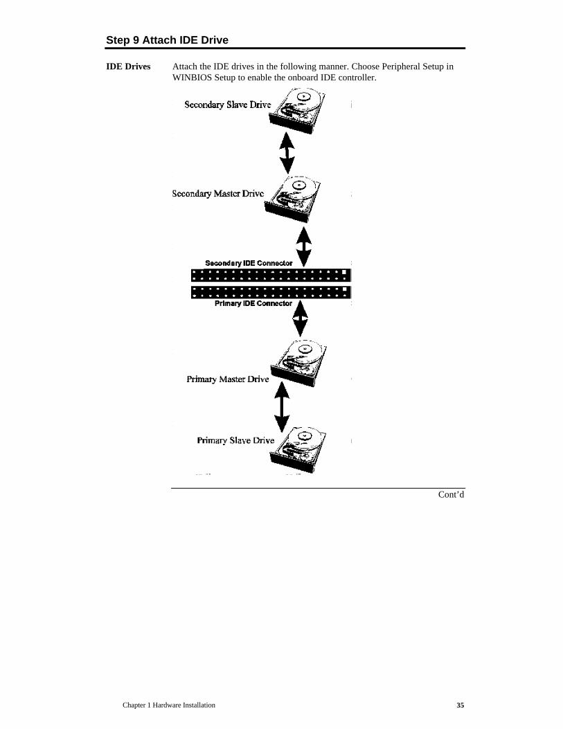
Step 9 Attach IDE Drive
IDE Drives Attach the IDE drives in the following manner. Choose Peripheral Setup inWINBIOS Setup to enable the onboard IDE controller.
Cont’d

Apollo IV PCI Pentium ISA Motherboard User’s Guide36
Step 9 Attach IDE Drive, Continued
Attach IDE Cable The primary IDE (Integrated Drive Electronics) hard disk drive connectoris marked PRIMARY. Both the primary master and the primary slave IDEdrives must be connected by cable to PRIMARY, as shown below.
PRIMARY is a 40-pin dual-inline berg that connects an IDE drive to theprimary onboard IDE connector. This motherboard supports IDE Modes 0, 1,2, 3, and 4, IDE prefetch, LBA (Logical Block Address) mode, high capacitydrives (over 528 MB), 32-bit data transfer, and fast IDE transfer. These IDEfeatures are configured in Peripheral Setup in the WINBIOS Setup utility.Disable the onboard IDE interface in Peripheral Setup to use an ISA ESDI,RLL, MFM, or SCSI hard disk drive controller.
Cont’d

Chapter 1 Hardware Installation 37
Step 9 Attach IDE Drive, Continued
PRIMARY Pinout The PRIMARY IDE pinout is:
Pin Use Pin Use1 -RESET 2 GND3 DATA7 4 DATA85 DATA6 6 DATA97 DATA5 8 DATA109 DATA4 10 DATA11
11 DATA3 12 DATA1213 DATA2 14 DATA1315 DATA1 16 DATA1417 DATA0 18 DATA1519 GND 20 KEY (N/C)21 N/C 22 GND23 -IOW 24 GND25 -IOR 26 GND27 IDERDY 28 ALE29 N/C 30 GND31 INT14 32 -IOCS1633 HA1 34 N/C35 HA0 36 HA237 -CS0 38 -CS139 -IDEACT 40 GND
Secondary IDE Controller The secondary IDE connector is labeled SECONDARY. Itconnects the secondary primary and slave IDE drives to the secondaryonboard IDE controller.
Attach the secondary master and slave IDE drives to IDE2 via a standard 40-pin IDE cable.
Cont’d
Apollo IV PCI Pentium ISA Motherboard User’s Guide38
Step 9 Attach IDE Drive, Continued
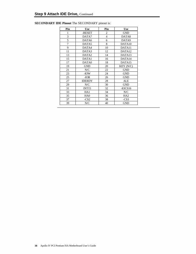
SECONDARY IDE Pinout The SECONDARY pinout is:
Pin Use Pin Use1 -RESET 2 GND3 DATA7 4 DATA85 DATA6 6 DATA97 DATA5 8 DATA109 DATA4 10 DATA11
11 DATA3 12 DATA1213 DATA2 14 DATA1315 DATA1 16 DATA1417 DATA0 18 DATA1519 GND 20 KEY (N/C)21 N/C 22 GND23 -IOW 24 GND25 -IOR 26 GND27 IDERDY 28 ALE29 N/C 30 GND31 INT15 32 -IOCS1633 HA1 34 N/C35 HA0 36 HA237 -CS2 38 -CS339 N/C 40 GND

Chapter 1 Hardware Installation 39
Step 10 Test and Configure
Review the following points before powering up:
• make sure that all adapter cards are seated properly,• make sure all connectors are properly installed,• make sure the CPU is seated properly,• make sure there are no screws or other foreign material on the
motherboard,• plug the system into a surge-protected power strip, and• make sure blank back panels are installed on the back of the chassis to
minimize RF emissions.
Start the Test Plug everything in and turn on the switch. If there are any signs of a problem,turn off the unit immediately. Reinstall the connectors. Call TechnicalSupport if there are problems.
BIOS Errors If the system operates normally, a display should appear on the monitor. TheBIOS Power On Self Test (POST) should execute.
If POST does not run successfully, it will beep or display error messages.Beeps indicate a serious problem with the system configuration or hardware.The Beep Code indicates the problem. AMIBIOS Beep Codes are defined inthe AMIBIOS Technical Reference. Make sure the affected part is properlyseated and connected. An error message is displayed if the error is lessserious. Recheck the system configuration or the connections.
Configure the System Run WINBIOS Setup. You must enter the requested information andsave the configuration data in CMOS RAM. The system will then reset, runPOST, and boot the operating system. See the following chapter forinformation about configuring the computer.


Chapter 2 WINBIOS Setup 41
2 WINBIOS® SetupIn ISA and EISA computers, the system parameters (such as amount ofmemory, type of disk drives and video displays, and many other elements) arestored in CMOS RAM. Unlike the DRAM (dynamic random access memory)that is used for standard system memory, CMOS RAM requires very littlepower. When the computer is turned off, a back-up battery provides power toCMOS RAM, which retains the system parameters. Every time the computeris powered-on, the computer is configured with the values stored in CMOSRAM by the system BIOS, which gains control when the computer is poweredon.
The system parameters are configured by a system BIOS Setup utility.Historically, BIOS Setup utilities have been character-based, requiredkeyboard input, and have had user interfaces that were not very intuitive.
Graphical Interface American Megatrends has a new type of system BIOS Setup utility.WINBIOS Setup has a graphical user interface the end user can access usinga mouse. The WINBIOS Setup code is so compact that it can reside on thesame ROM as the system BIOS. The system configuration parameters are setby WINBIOS Setup.
Since WINBIOS Setup resides in the ROM BIOS, it is available each time thecomputer is turned on.
Starting WINBIOS Setup As POST executes, the following appears:
Hit <DEL> if you want to run SETUP
Press <Del> to run WINBIOS Setup.

Apollo IV PCI Pentium ISA Motherboard User’s Guide42
Using a Mouse with WINBIOS Setup
WINBIOS Setup has a built-in mouse driver and can be accessed by either aserial mouse or PS/2-style mouse. WINBIOS Setup supports Microsoft-Compatible serial mice and all PS/2-type mice.
The mouse click functions are: single click to change or select both globaland current fields and double click to perform an operation in the selectedfield.
Using the Keyboard with WINBIOS Setup
WINBIOS has a built-in keyboard driver that uses simple keystrokecombinations:
Keystroke Action<Tab> Change or select a global field.
<→, ←, ↑, ↓ Change or select the current field.<Enter> Perform an operation in the current field.
+ Increment a value.– Decrement a value.
<Esc> Abort any window function.<PgUp> Return to the previous screen.<PgDn> Advance to the next screen.<Home> Returns to the beginning of the text.<End> Advance to the end of the text.
<Ctrl><Alt><+> Change to high speed.<Ctrl><Alt><-> Change to low speed.

Chapter 2 WINBIOS Setup 43
WINBIOS Setup Menu
The WINBIOS Setup main menu is organized into four sections. Each ofthese sections corresponds to a section in this chapter.
Each section contains several icons. Clicking on each icon activates a specificAMIBIOS function. The WINBIOS Setup main windows and relatedfunctions are described on the next screen.
Main Windows The WINBIOS Setup main windows are:
• Setup, described in Section 1 has icons that permit you to set systemconfiguration options such as date, time, hard disk type, floppy type, andmany others,
• Security, described in Section 2 has three icons that control AMIBIOSsecurity features, and
• Utilities, described in Section 3 sets the screen color and allows languagechanges,
• Default, described in Section 4 has three icons that permit you to select agroup of settings for all WINBIOS Setup options.

Apollo IV PCI Pentium ISA Motherboard User’s Guide44
Section 1 SetupStandard Setup
Standard Setup options are displayed by choosing the Standard icon from theWINBIOS Setup main menu. All Standard Setup options are described in thissection.
Date/Time Select the Standard option. Select the Date and Time icon. The current valuesfor each category are displayed. Enter new values through the keyboard.
Floppy Drive A: and B: Move the cursor to these fields via ↑ and ↓ and select the floppy type.The settings are 360 KB 5¼ inch, 1.2 MB 5¼ inch, 720 KB 3½ inch, 1.44 MB3½ inch, or 2.88 MB 3½ inch.
Primary Master, Primary Slave, Secondary Master, Secondary Slave Select one of thesehard disk drive icons to configure the hard disk drive named in the option.Select Auto from the drive parameters screen to let AMIBIOS automaticallyconfigure the drive. A screen with a list of drive parameters appears. Click onOK to configure the drive.
Drive Type How to ConfigureSCSI Select Type. Select Not Installed in the drive parameter screen. The SCSI
drivers provided by the SCSI drive or SCSI host adapter manufacturer shouldallow you to configure the SCSI drive.
IDE Select Type. Select Auto to let AMIBIOS determine the parameters. Click onOK when AMIBIOS displays the drive parameters.
Select LBA/Large Mode. Select On if the drive has a capacity greater than540 MB.
Select Block Mode. Select On to allow block mode data transfers.
Select 32-Bit Transfer. Select On to allow 32-bit data transfers.
Select the PIO Mode. It is best to select Auto to allow AMIBIOS to determinethe PIO mode. If you select a PIO mode that is not supported by the IDEdrive, the drive will not work properly. If you are absolutely certain that youknow the drive’s PIO mode, select PIO mode 0 - 5, as appropriate.
CD-ROM Select Type. Select CDROM. Click on OK when AMIBIOS displays the driveparameters.
StandardMFM Drive
Select Type. You must know the drive parameters. Select the drive type thatexactly matches your drive’s parameters.
Non-Standard
MFM Drive
Select Type. If the drive parameters do not match the drive parameters listedfor drive types 1 - 46, select User and enter the correct hard disk driveparameters.
Cont’d

Chapter 2 WINBIOS Setup 45
Standard Setup, Continued
Entering Drive Parameters You can also enter the hard disk drive parameters. The driveparameters are:
Parameter Description
Type The number for a drive with certain identification parameters.
Cylinders The number of cylinders in the disk drive.
Heads The number of heads.
WritePrecompensation
The actual physical size of a sector gets progressively smaller as the trackdiameter diminishes. Yet each sector must still hold 512 bytes. Writeprecompensation circuitry on the hard disk compensates for the physicaldifference in sector size by boosting the write current for sectors on innertracks. This parameter is the track number on the disk surface wherewrite precompensation begins.
Landing Zone This number is the cylinder location where the heads normally park whenthe system is shut down.
Sectors The number of sectors per track. MFM drives have 17 sectors per track.RLL drives have 26 sectors per track. ESDI drives have 34 sectors pertrack. SCSI and IDE drives have even more sectors per track.
Capacity The formatted capacity of the drive is the number of heads times thenumber of cylinders times the number of sectors per track times 512(bytes per sector).
Cont’d

Apollo IV PCI Pentium ISA Motherboard User’s Guide46
Standard Setup, Continued
Hard Disk Drive Types
Type Cylinders Heads WritePrecompensation
LandingZone
Sectors Capacity
1 306 4 128 305 17 10 MB
2 615 4 300 615 17 20 MB
3 615 6 300 615 17 31 MB
4 940 8 512 940 17 62 MB
5 940 6 512 940 17 47 MB
6 615 4 65535 615 17 20 MB
7 462 8 256 511 17 31 MB
8 733 5 65535 733 17 30 MB
9 900 15 65535 901 17 112 MB
10 820 3 65535 820 17 20 MB
11 855 5 65535 855 17 35 MB
12 855 7 65535 855 17 50 MB
13 306 8 128 319 17 20 MB
14 733 7 65535 733 17 43 MB
16 612 4 0 663 17 20 MB
17 977 5 300 977 17 41 MB
18 977 7 65535 977 17 57 MB
19 1024 7 512 1023 17 60 MB
20 733 5 300 732 17 30 MB
21 733 7 300 732 17 43 MB
22 733 5 300 733 17 30 MB
23 306 4 0 336 17 10 MB
24 925 7 0 925 17 54 MB
25 925 9 65535 925 17 69 MB
26 754 7 754 754 17 44 MB
27 754 11 65535 754 17 69 MB
28 699 7 256 699 17 41 MB
29 823 10 65535 823 17 68 MB
30 918 7 918 918 17 53 MB
31 1024 11 65535 1024 17 94 MB
32 1024 15 65535 1024 17 128 MB
33 1024 5 1024 1024 17 43 MB
34 612 2 128 612 17 10 MB
35 1024 9 65535 1024 17 77 MB
36 1024 8 512 1024 17 68 MB
37 615 8 128 615 17 41 MB
38 987 3 987 987 17 25 MB
39 987 7 987 987 17 57 MB
40 820 6 820 820 17 41 MB
41 977 5 977 977 17 41 MB
42 981 5 981 981 17 41 MB
43 830 7 512 830 17 48 MB
44 830 10 65535 830 17 69 MB
45 917 15 65535 918 17 114 MB
46 1224 15 65535 1223 17 152 MB
AMIBIOS automatically sets IDE drive parameters. Select USER to enter MFM, ESDI, or RLL driveparameters. Select Not Installed for SCSI drives. Select CDROM for CD-ROM drives.
Chapter 2 WINBIOS Setup 47
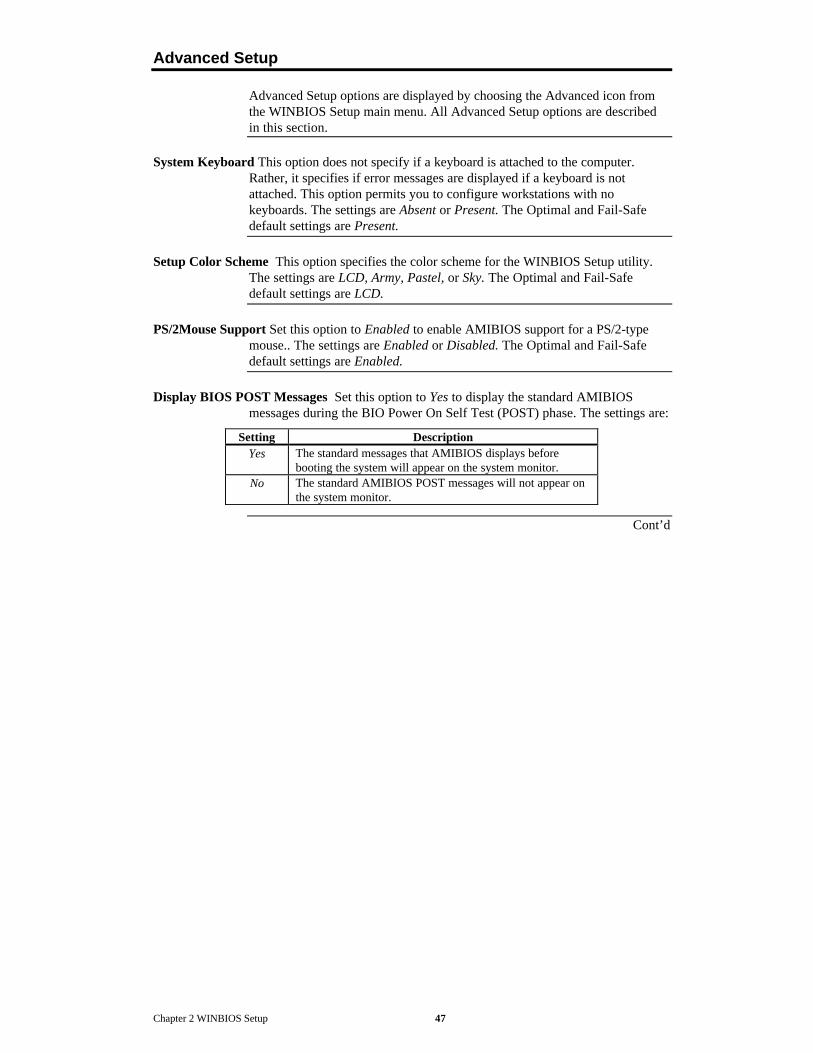
Advanced Setup
Advanced Setup options are displayed by choosing the Advanced icon fromthe WINBIOS Setup main menu. All Advanced Setup options are describedin this section.
System Keyboard This option does not specify if a keyboard is attached to the computer.Rather, it specifies if error messages are displayed if a keyboard is notattached. This option permits you to configure workstations with nokeyboards. The settings are Absent or Present. The Optimal and Fail-Safedefault settings are Present.
Setup Color Scheme This option specifies the color scheme for the WINBIOS Setup utility.The settings are LCD, Army, Pastel, or Sky. The Optimal and Fail-Safedefault settings are LCD.
PS/2Mouse Support Set this option to Enabled to enable AMIBIOS support for a PS/2-typemouse.. The settings are Enabled or Disabled. The Optimal and Fail-Safedefault settings are Enabled.
Display BIOS POST Messages Set this option to Yes to display the standard AMIBIOSmessages during the BIO Power On Self Test (POST) phase. The settings are:
Setting DescriptionYes The standard messages that AMIBIOS displays before
booting the system will appear on the system monitor.No The standard AMIBIOS POST messages will not appear on
the system monitor.
Cont’d

Apollo IV PCI Pentium ISA Motherboard User’s Guide48
Advanced Setup, Continued
Display Add-On ROM Messages Set this option to Yes to display any additional screenmessages from an option ROM. This option can only be selected if theDisplay BIOS POST Message option is set to No. The settings are:
Setting DescriptionYes Display messages from an option ROM.No Do not display messages from an option ROM.
The Optimal and Fail-Safe default settings are No.
Pause on Config. Screen This option specifies the length of time that the AMIBIOSconfiguration screen appears. The settings are 2 (seconds), 3, 4, 5, 6, 7, 8, 9,10, 11, 12, 13, 14, or Disabled. The Optimal and Fail-Safe default settingsare Disabled.
Boot Up Num Lock Set this option to On to turn the Num Lock key On at system boot. Thesettings are On or Off. The Optimal and Fail-Safe default settings are On.
Password CheckThis option enables the password check option every time the system boots orthe end user runs Setup. If Always is chosen, a user password prompt appearsevery time the computer is turned on. If Setup is chosen, the password promptappears if WINBIOS is executed. The Optimal and Power-On defaults areSetup.
Boot To OS/2 Set this option to Yes if running OS/2 operating system and using more than64 MB of system memory on the motherboard. The settings are Yes or No.The Optimal and Fail-Safe default settings are No.
Floppy Drive Seek Set this option to Enabled to specify that floppy drive A: will perform aSeek operation at system boot. The settings are Disabled or Enabled. TheOptimal and Fail-Safe default settings are Disabled.
Cont’d

Chapter 2 WINBIOS Setup 49
Advanced Setup, Continued
Floppy Drive Swap Set this option to Enabled to permit drives A: and B: to be swapped. Thesettings are Enabled or Disabled. The Optimal and Fail-Safe default settingsare Disabled.
Floppy Access Control This option specifies the read/write access that is set when bootingfrom a floppy drive. The settings are Read/Write or Read-Only. The Optimaland Fail-Safe default settings are Read/Write.
Hard Disk Access Control This option specifies the read/write access that is set when bootingfrom a hard disk drive. The settings are Read/Write or Read-Only. TheOptimal and Fail-Safe default settings are Read/Write.
S.M.A.R.T. For Hard Disks Set this option to Enabled to permit AMIBIOS to use theSMART (Self Monitoring Analysis and Reporting Technology) protocol forreporting server system information over a network. The settings are Enabledor Disabled. The Optimal and Fail-Safe default settings are Disabled.
Primary Master ARMD Emulator AsPrimary Slave ARMD Emulator AsSecondary Master ARMD Emulator AsSecondary Slave ARMD Emulator As These options specify the type of standard PC drive
that an ARMD drive will use when attached as a master or slave to thespecified IDE channel. The settings are Auto (AMIBIOS automaticallydetermines the correct type of drive emulation), Floppy, or Hard Disk. TheOptimal and Fail-Safe default settings are Auto.
If Auto is selected, AMIBIOS configures ARMD drives as follows:
Type of ARMD Device Drive Emulation ConfiguredLS120 Floppy
Iomega Zip drive Hard DiskMagneto-Optical drive Hard Disk
Cont’d

Apollo IV PCI Pentium ISA Motherboard User’s Guide50
Advanced Setup, Continued
1st Boot Device This option sets the type of device for the first boot drives that the AMIBIOSattempts to boot from after AMIBIOS POST completes. The settings areDisabled, Network, Floppy, ARMD-FDD, ARMD-HDD, ATAPI, SCSI,CDROM, 1st IDE-HDD, 2nd IDE-HDD, 3rd IDE HDD, or 4th IDE-HDD. TheOptimal and Fail-Safe default settings are Disabled.
2nd Boot Device This option sets the type of device for the second boot drives that theAMIBIOS attempts to boot from after AMIBIOS POST completes. Thesettings are Disabled, Floppy, ARMD-FDD, ARMD-HDD, ATAPI, SCSI,CDROM, 1st IDE-HDD, 2nd IDE-HDD, 3rd IDE HDD, or 4th IDE-HDD. TheOptimal and Fail-Safe default settings are Disabled.
3rd Boot Device This option sets the type of device for the third boot drives that the AMIBIOSattempts to boot from after AMIBIOS POST completes. The settings areDisabled, Floppy, ARMD-FDD, ARMD-HDD, ATAPI, CDROM, 1st IDE-HDD, 2nd IDE-HDD, 3rd IDE HDD, or 4th IDE-HDD. The default settingsare ARMD-HDD.
4th Boot Device This option sets the type of device for the third boot drives that the AMIBIOSattempts to boot from after AMIBIOS POST completes. The settings areDisabled, Floppy, ARMD-FDD, ARMD-HDD, ATAPI, CDROM, 1st IDE-HDD, 2nd IDE-HDD, 3rd IDE HDD, or 4th IDE-HDD. The default settingsare Disabled.
Try Other Boot Devices Set this option to Yes to instruct AMIBIOS to attempt to boot fromany other drive in the system if it cannot find a boot drive among the drivesspecified in the 1st Boot Device, 2nd Boot Device, 3rd Boot Device, and 4th
Boot Device options. The settings are Yes or No. The Optimal and Fail-Safedefault settings are Yes.
Cont’d

Chapter 2 WINBIOS Setup 51
Advanced Setup, Continued
External Cache Set this option to Enabled to enable L2 secondary (external) cache memory.The settings are Enabled or Disabled. The Optimal default setting isEnabled. The Fail-Safe default setting is Disabled.
Caching Controller Set this option to Yes if a cache controller is installed in the computer.
Setting Description
Absent(the
defaultsetting)
To comply with the PCI specifications, PCI adapter cardsmust be reset every time the CPU is reset. When the enduser forces a soft reset by pressing <Ctrl> <Alt> <Del>, onlythe CPU is reset. When this option is set to No, all softresets are converted to hard resets, and all PCI adapter cardsare reset when the CPU is reset.
Present Soft resets still behave like soft resets when Yes is selected.Select this option if a caching controller is installed in thecomputer. Soft resets must not generate a hard reset if acaching controller is used. If a hard reset is generated, a PCIcaching controller card cannot flush data from cache memoryto a hard disk drive before the reset.
Video Shadow C000,32K This option controls the location of the contents of video ROM. Thesettings are:
Setting Description
Shadow The contents of the video ROM area (C0000h - C7FFFh) are written to thecorresponding address in RAM.
Cached The contents of the video ROM area (C0000h - C7FFFh) are written to thecorresponding RAM address and may be read from or written to cachememory.
Disabled The video ROM is not copied to RAM. The contents of the video ROMcannot be read from or written to cache memory.
The Optimal default setting is Cached. The Fail-Safe default setting isDisabled.
Shadow C800,16KShadow CC00,16KShadow D000,16KShadow D400,16KShadow D800,16KShadow DC00,16K These options enable shadowing of the contents of the ROM area in the
option title.
Setting Description
Shadow The contents of the ROM area are written to the corresponding address inRAM for faster execution.
Cached The contents of the ROM area are written to the corresponding RAMaddress and can be read from or written to cache memory.
Disabled The ROM is not copied to RAM. The contents of the video ROM cannot beread from or written to cache memory.
The Optimal and Fail-Safe settings are Disabled.

Apollo IV PCI Pentium ISA Motherboard User’s Guide52
Chipset Setup
The AMIBIOS Setup options described in this section are selected bychoosing the Chipset Setup icon from the Setup section on the WINBIOSSetup main menu.
USB Function Set this option to Enabled to enable the system BIOS USB (Universal SerialBus) functions. The settings are Enabled or Disabled. The Optimal and Fail-Safe default settings are Enabled.
USB Keyboard/Mouse Legacy Support Set this option to Enabled to enable USB support forlegacy keyboards and mice. The settings are Enabled or Disabled. TheOptimal and Fail-Safe default settings are Enabled.
ISA 8 Bit I/O Recovery Time This option specifies the length of the delay that is added to theCPU cycle between consecutive 8-bit I/O operations. The length of the delayis related to the CPU type and frequency. The settings are 1 Sysclock, 2Sysclocks, 3 Sysclocks, 4 Sysclocks, 5 Sysclocks, 6 Sysclocks, 8 Sysclocks, orDisabled. The Optimal and Fail-Safe default settings are Disabled.
ISA 16 Bit I/O Recovery This option specifies the length of the delay that is added to the CPUcycle between consecutive 16-bit I/O operations. The length of the delay isrelated to the CPU type and frequency. The settings are 1 Sysclock, 2Sysclocks, 3 Sysclocks, 4 Sysclocks, or Disabled. The Optimal and Fail-Safedefault settings are Disabled.

Chapter 2 WINBIOS Setup 53
Power Management Setup
The AMIBIOS Setup options described in this section are selected bychoosing the Power Management Setup icon from the Setup section on theAMIBIOS Setup main menu.
Power Management/APM Set this option to Enabled to enable the Intel Triton 2 powermanagement features and APM (Advanced Power Management). The settingsare Enabled, Inst-On (instant-on), or Disabled. The Optimal and Fail-Safedefault settings are Disabled.
Instant On Support Set this option to Enabled to enable AMIBIOS support for the IntelInstantON specification. The settings are Enabled or Disabled. The Optimaland Fail-Safe default settings are Disabled.
Green PC Monitor Power State This option specifies the power state that the green PC-compliant video monitor enters when AMIBIOS places it in a power savingstate after the specified period of display inactivity has expired. The settingsare Off, Standby, Suspend, or Disabled. The Optimal and Fail-Safe defaultsettings are Standby.
Video Power Down Mode This option specifies the power conserving state that the VESAVGA video subsystem enters after the specified period of display inactivityhas expired. The settings are Disabled, Standby, or Suspend. The Optimaland Fail-Safe default settings are Disabled.
Hard Disk Power Down Mode This option specifies the power conserving state that the harddisk drive enters after the specified period of hard drive inactivity hasexpired. The settings are Disabled, Standby, or Suspend. The Optimal andFail-Safe default settings are Disabled.
Hard Disk Timeout (Minute) This option specifies the length of a period of hard disk driveinactivity. When this length of time expires, the computer enters power-conserving state specified in the Hard Disk Power Down Mode option (seethe previous screen). The settings are Disabled and 1 Min. through 15 Min in1 minute intervals. The Optimal and Fail-Safe default settings are Disabled.
Standby/Suspend Timer Unit This option specifies the unit of time used for the Standby andSuspend timeout periods. The settings are 4 msec, 4 sec, 32 sec, or 4 min.The Optimal and Fail-Safe default settings are 4 min.
Standby Timeout This option specifies the length of a period of system inactivity while in Fullpower on state. When this length of time expires, the computer entersStandby power state. The settings are Disabled, 4 min, 8 min, up to andincluding 508 minutes, in increments of 4 minutes. The Optimal and Fail-Safedefault settings are Disabled.
Suspend Timeout This option specifies the length of a period of system inactivity while inStandby state. When this length of time expires, the computer enters Suspendpower state. The settings are Disabled, 4 min, 8 min, up to and including 508minutes, in increments of 4 minutes. The Optimal and Fail-Safe defaultsettings are Disabled.
Cont’d

Apollo IV PCI Pentium ISA Motherboard User’s Guide54
Power Management Setup, Continued
Slow Clock Ratio This option specifies the speed at which the system clock runs in powersaving states. The settings are expressed as a ratio between the normal CPUclock speed and the CPU clock speed when the computer is in the power-conserving state. The settings are 0-12.5%, 12.5-25%, 25-37.5%, 37.5-50%,50-62.5%, 62.5-75%, or 75-87.5%. The Optimal and Fail-Safe defaults are1:8.
Display Activity This option specifies if AMIBIOS is to monitor display activity for powerconservation purposes. When this option is set to Monitor and there is nodisplay activity for the length of time specified in the Standby Timeout(Minutes) option, the computer enters a power savings state. The settings areMonitor or Ignore. The Optimal and Fail-Safe default settings are Ignore.
Device 6 (Serial Port 1)Device 7 (Serial Port 2)Device 8 (Parallel Port)Device 5 (Floppy Disk)Device 0 (Primary Master IDE)Device 1 (Primary Salve IDE)Device 2 (Secondary Master IDE)Device 3 (Secondary Slave IDE) When set to Monitor, these options enable event monitoring
on the specified hardware interrupt request line. If set to Monitor and thecomputer is in a power saving state, AMIBIOS watches for activity on thespecified IRQ line. The computer enters the Full On state if any activityoccurs. AMIBIOS reloads the Standby and Suspend timeout timers if activityoccurs on the specified IRQ line.
The settings for each of these options are Monitor or Ignore. The Optimal andFail-Safe default settings are Ignore.

Chapter 2 WINBIOS Setup 55
PCI/PnP Setup
Choose the PCI/PnP Setup icon from the WINBIOS Setup screen to displaythe PCI and Plug and Play Setup options, described below.
Plug and Play-Aware OS Set this option to Yes if the operating system in this computer isaware of and follows the Plug and Play specification. Windows 95 is PnP-aware. The settings are Yes or No. The Optimal and Fail-Safe default settingsare No.
PCI VGA Palette Snoop When this option is set to Enabled, multiple VGA devices operatingon different buses can handle data from the CPU on each set of paletteregisters on every video device. Bit 5 of the command register in the PCIdevice configuration space is the VGA Palette Snoop bit (0 is disabled). Forexample: if there are two VGA devices in the computer (one PCI and oneISA) and the VGA Palette Snoop bit is:
Snoop Bit ActionDisabled Data read and written by the CPU is only directed to the PCI VGA device's
palette registers.Enabled Data read and written by the CPU is directed to the both the PCI VGA device
palette registers and the ISA VGA device palette registers, and the paletteregisters of both devices can be identical.
This option must be set to Enabled if an ISA adapter card installed in thesystem uses VGA palette snooping. The Optimal and Fail-Safe defaultsettings are Disabled.
Allocate IRQ to PCI VGA Set this option to Yes to allocate an IRQ to a VGA adapter cardthat uses the PCI local bus. The settings are Yes or No. The Optimal and Fail-Safe default settings are Yes.
PCI Slot-1 Latency TimerPCI Slot-2 Latency TimerPCI Slot-3 Latency TimerPCI Slot-4 Latency Timer These options specify the latency timings (in PCI clocks) for PCI
devices installed in the four PCI expansion slots. The settings are 32, 64, 96,128, 160, 192, 224, or 248. The Optimal and Fail-Safe default settings are 64.
USB Device Latency Timer This option specifies the latency timings (in PCI clocks) for USBdevices installed in the computer. The settings are 32, 64, 96, 128, 160, 192,224, or 248. The Optimal and Fail-Safe default settings are 64.
USB Device IRQ Preference These options specify the IRQ priority for USB devices installedin the computer. The settings are Auto, IRQ5, IRQ9, IRQ10, IRQ11, IRQ14,and IRQ15, in priority order. If Auto is selected, AMIBIOS automaticallydetermines the optimal IRQ priority order. The Optimal and Fail-Safe defaultsettings are Auto.
PCI Slot-1 IRQ PreferencePCI Slot-2 IRQ PreferencePCI Slot-3 IRQ PreferencePCI Slot-4 IRQ Preference These options specify the IRQ priority for PCI devices installed in
the four PCI expansion slots. The settings are Auto, IRQ5, IRQ9, IRQ10,IRQ11, IRQ 14, and IRQ15, in priority order. If Auto is selected, AMIBIOSautomatically determines the optimal IRQ priority order. The Optimal andFail-Safe default settings are Auto.
Cont’d

Apollo IV PCI Pentium ISA Motherboard User’s Guide56
PCI/PnP Setup, Continued
IRQ3IRQ4IRQ5IRQ7IRQ9IRQ10IRQ11IRQ12IRQ14IRQ15 These options specify the bus that the specified IRQ line is used on. These
options allow you to reserve IRQs for legacy ISA adapter cards. These optionsdetermine if AMIBIOS should remove an IRQ from the pool of availableIRQs passed to devices that are configurable by the system BIOS. Theavailable IRQ pool is determined by reading the ESCD NVRAM. If moreIRQs must be removed from the pool, the end user can use these options toreserve the IRQ by assigning an ISA setting to it. Onboard I/O is configuredby AMIBIOS. All IRQs used by onboard I/O are configured as PCI, PnP, orPCI/PnP. IRQ14 and 15 will not be available if the onboard Triton 2 PCI IDEis enabled. If all IRQs are set to ISA and IRQ14 and 15 are allocated to theonboard PCI IDE, IRQ9 will still be available for PCI and PnP devices,because at least one IRQ must be available for PCI and PnP devices. Thesettings are ISA, PnP, PCI/PnP, or PCI. The Optimal and Fail-Safe defaultsettings are:
Option Optimal Default Fail-Safe DefaultIRQ3 PnP PCI/PnPIRQ4 PnP PCI/PnPIRQ5 PCI/PnP PCI/PnPIRQ7 PnP PCI/PnPIRQ9 PCI/PnP PCI/PnPIRQ10 PCI/PnP PCI/PnPIRQ11 PCI/PnP PCI/PnPIRQ12 PnP PnPIRQ14 PCI/PnP PCI/PnPIRQ5 PCI/PnP PCI/PnP
DMA Channel 0DMA Channel 1DMA Channel 3DMA Channel 5DMA Channel 6DMA Channel 7 These options allow you to specify the bus type used by each DMA channel.
The settings are PnP or ISA. The Optimal and Fail-Safe default settings arePnP.
Reserved ISA Card Memory Size This option specifies the size of the memory area reservedfor legacy ISA adapter cards. The settings are Disabled, 16K, 32K, or 64K.The Optimal and Fail-Safe default settings are Disabled.
Reserved ISA Card Memory Address This option specifies the beginning address (in hex) ofthe reserved memory area. The specified ROM memory area is reserved foruse by legacy ISA adapter cards.
The settings are C0000, C4000, C8000, CC000, D0000, D4000, D8000, orDC000. The Optimal and Fail-Safe default settings are C4000.

Chapter 2 WINBIOS Setup 57
Peripheral Setup
Choose the Peripheral Setup icon from the WINBIOS Setup screen to displaythe Peripheral Setup options, described below.
Onboard Floppy Controller Set this option to Enabled to enable the floppy drive controlleron the motherboard. The settings are Enabled or Disabled. The Optimal andFail-Safe default settings are Enabled.
Onboard Primary/Secondary IDE This option specifies the IDE channels on the onboardIDE controller that will be used. The settings are Disabled, Primary,Secondary, or Both. The Optimal and Fail-Safe default settings are Disabled.
Onboard IDE Bus Master Set this option to Enabled to specify that the IDE controller on thePCI local bus includes a bus mastering capability. The settings are Enabled orDisabled. The Optimal and Fail-Safe default settings are Disabled.
Primary PrefetchSecondary Prefetch These options specify the IDE channel or channel where prefetch is
enabled. The settings are Disabled, Master, Slave, or Both. There are nodefault settings.
Offboard PCI/ISA IDE Card This option specifies if an offboard PCI IDE controller adaptercard is installed in the computer. You must choose ISA if an ISA IDE card isinstalled or the PCI expansion slot on the motherboard where the offboardPCI IDE controller is installed. If an offboard ISA or PCI IDE controller isused, the onboard IDE controller is automatically disabled. The settings areAuto (AMIBIOS automatically determines where the offboard PCI IDEcontroller adapter card is installed), Absent, ISA, Slot1, SLot2, Slot3, orSlot4. The Optimal And Fail-Safe default settings are Auto.
In the AMIBIOS for the Intel Triton II ISA chipset, this option forces IRQ14and IRQ15 to a PCI slot on the PCI Local bus. This is necessary to supportnon-compliant ISA IDE controller adapter cards.
If an offboard PCI IDE controller adapter card is installed in the computer,you must also set the Offboard PCI IDE Primary IRQ and Offboard PCIIDE Secondary IRQ options.
Offboard Primary/Secondary This option specifies the IDE controller channels used by theoffboard IDE adapter card. The settings are Disabled, Primary, Secondary, orBoth. There are no Optimal and Fail-Safe default settings.
Offboard PCI IDE Primary IRQOffboard PCI IDE Secondary IRQ These options specify the PCI interrupt used by the
primary or secondary IDE channel on the offboard PCI IDE controller. Thesettings are Disabled, Hardwired, INTA, INTB, INTC, or INTD. The Optimaland Fail-Safe default settings are Disabled.
Onboard Serial Port1 IRQ This option specifies the IRQ used for serial port1. The settingsare IRQ4 or Disabled. The Optimal default setting is IRQ4. The Fail-Safedefault setting is Disabled.
Cont’d

Apollo IV PCI Pentium ISA Motherboard User’s Guide58
Peripheral Setup, Continued
Onboard Serial Port1 Address This option specifies the base I/O port address of serial port 1.The settings are Auto (AMIBIOS automatically determines the correct baseI/O port address), Disabled, 3F8h, or 3E8h. The Optimal default setting is3F8h. The Fail-Safe default setting is Disabled.
Onboard Serial Port1 FIFO Set this option to Enabled to enable the serial port1 FIFO buffer.The settings are Enabled or Disabled. The Optimal and Fail-Safe defaultsettings are Disabled.
Onboard Serial Port2 IRQ This option specifies the IRQ used for serial port2. The settingsare IRQ3 or Disabled. The Optimal default setting is IRQ3. The Fail-Safedefault setting is Disabled.
Onboard Serial Port2 Address This option specifies the base I/O port address of serial port 2.The settings are Auto (AMIBIOS automatically determines the correct baseI/O port address), Disabled, 2F8h, or 2E8h. The Optimal default setting is3F8h. The Fail-Safe default setting is Disabled.
Onboard Serial Port2 FIFO Set this option to Enabled to enable the serial port2 FIFO buffer.The settings are Enabled or Disabled. The Optimal and Fail-Safe defaultsettings are Disabled.
Onboard Serial Port2 Mode This option specifies the serial port 2 mode. The settings areNormal or IrDA (Infrared). The Optimal and Fail-Safe default settings areNormal.
IR Duplex Mode This option selects the infrared transmission method. The settings are Fullor Half. The Optimal and Fail-Safe default settings are Full.
IrDA Protocol This option specifies the infrared standard used for the serial port2 infraredcapability. The settings are 1.6 us or 3/16. The Optimal and Fail-Safe defaultsettings are unspecified because IR is not the default setting for the SerialPort2 Mode option.
Onboard Parallel Port IRQ This option specifies the IRQ used by the parallel port. Thesettings are Disabled, IRQ 5, or IRQ 7. The Optimal default setting is IRQ 7.The Fail-Safe default setting is Disabled.
Cont’d

Chapter 2 WINBIOS Setup 59
Peripheral Setup, Continued
Onboard Parallel Port Address This option specifies the base I/O port address of the parallelport on the motherboard. The settings are Disabled, 378h, or 278h. TheOptimal default setting is 378h. The Fail-Safe default setting is Disabled.
Onboard Parallel Port Mode This option specifies the parallel port mode. The Optimal defaultsetting is Normal. The Fail-Safe default setting is Disabled. The settings are:
Setting DescriptionNormal The normal parallel port mode is used.SPP/EPP
The parallel port can be used with devices that adhere to the SPP or EnhancedParallel Port (EPP) specification. EPP uses the existing parallel port signals toprovide asymmetric bidirectional data transfer driven by the host device.
ECP The parallel port can be used with devices that adhere to the Extended CapabilitiesPort (ECP) specification. ECP uses the DMA protocol to achieve data transfer ratesup to 2.5 Megabits per second. ECP provides symmetric bidirectionalcommunication.
EPP Version This option specifies the Enhanced Parallel Port specification version numberthat is used if the Parallel Port Mode option is set to EPP. This option canonly be selected if the Parallel Port Mode option is set to EPP
The settings are 1.7 or 1.9. There are no Optimal and Fail-Safe defaultsettings because the default setting for the Parallel Port Mode option is notEPP.
Parallel Port DMA Channel This option is only available if the setting for the Parallel PortMode option is ECP. This option sets the DMA channel used by the parallelport. The settings are (DMA Channel) 0, 1 or 3. The Optimal and Fail-Safedefault settings are 3.

Apollo IV PCI Pentium ISA Motherboard User’s Guide60
Section 2 SecurityThree icons appear in this part of the WINBIOS Setup screen:
• Supervisor (Password),• User (Password), and• Anti-Virus.
Two Levels of Passwords Both the Supervisor and the User icons configure password support.If you use both, the Supervisor password must be set first.
The system can be configured so that all users must enter a password everytime the system boots or when WINBIOS Setup is executed, using either orboth the Supervisor password or User password.
AMIBIOS Password Support
The Supervisor and User icons activate two different levels of passwordsecurity.
If WINBIOS Setup has an optional password feature. The system can beconfigured so that all users must enter a password every time the system bootsor when WINBIOS Setup is executed.

Chapter 2 WINBIOS Setup 61
Setting a Password
The password check option is enabled in Advanced Setup (see the AdvancedSetup section ) by choosing either Always (the password prompt appears everytime the system is powered on) or Setup (the password prompt appears onlywhen WINBIOS is run). The password is encrypted and stored in NVRAM.
As shown on the above screen, you are prompted for a 1 – 6 characterpassword. You can either type the password on the keyboard or select eachletter of the password, one at a time, using the mouse. The password does notappear on the screen when typed. Make sure you write it down. If you forgetit, you must drain NVRAM and reconfigure.
If You Do Not Want to Use a Password Just press <Enter> when the password promptappears.
Changing a Password
Select the Supervisor or User icon from the Security section of the WINBIOSSetup main menu. Enter the password and press <Enter>. The screen doesnot display the characters entered. After the new password is entered, retypethe new password as prompted and press <Enter>.
If the password confirmation is incorrect, an error message appears. If thenew password is entered without error, press <Esc>. The password is storedin NVRAM after WINBIOS completes. The next time the system boots, apassword prompt appears if the password function is present and enabled.
Remember the Password Keep a record of the new password when the password is changed. Ifyou forget the password, you must erase the system configuration informationin NVRAM (Non-Volatile Random Access Memory).

Apollo IV PCI Pentium ISA Motherboard User’s Guide62
Anti-Virus
When this icon is selected from the Security section of the WINBIOS Setupmain menu, AMIBIOS issues a warning when any program (or virus) issues aDisk Format command or attempts to write to the boot sector of the hard diskdrive. The settings are Enabled or Disabled. If enabled, the following appearswhen a write is attempted to the boot sector. You may have to type N severaltimes to prevent the boot sector write.
Boot Sector Write!!!Possible VIRUS: Continue (Y/N)? _
The following appears after any attempt to format any cylinder, head, orsector of any hard disk drive via the BIOS INT 13 Hard Disk Drive Service:
Format!!!Possible VIRUS: Continue (Y/N)? _

Chapter 2 WINBIOS Setup 63
Section 3 UtilityThe following icons appear in this section of the WINBIOS Setup mainscreen:
Detect IDE Choose this option to let AMIBIOS automatically detect and configure theparameters for an IDE hard disk drive.
Language If this feature is enabled, you can select WINBIOS Setup messages indifferent languages.

Apollo IV PCI Pentium ISA Motherboard User’s Guide64
Section 4 DefaultThe icons in this section permit you to select a group of settings for allWINBIOS Setup options. Not only can you use these icons to quickly setsystem configuration parameters, you can choose a group of settings that havea better chance of working when the system is having configuration-relatedproblems.
Original Choose the Original icon to return to the system configuration values presentin WINBIOS Setup when you first began this WINBIOS Setup session.
Optimal You can load the optimal default settings for the WINBIOS byselecting the Optimal icon. The Optimal default settings are best-case valuesthat should optimize system performance. If NVRAM is corrupted, theOptimal settings are loaded automatically.
Fail-Safe You can load the Fail-Safe WINBIOS Setup option settings by selecting theFail-Safe icon from the Default section of the WINBIOS Setup main menu.
The Fail-Safe settings provide far from optimal system performance, but arethe most stable settings. Use this option as a diagnostic aid if the system isbehaving erratically.

Chapter 2 WINBIOS Setup 65
3 Programming the Flash ROMAll versions of the Apollo IV motherboard use Flash EPROM to store thesystem BIOS. The advantage of Flash EPROM is the EPROM chip does nothave to be replaced to update the BIOS. The end user can actually reprogramthe BIOS, using a ROM file supplied by American Megatrends.
Programming the Flash EPROM
Step Action1 Turn power off. Make sure the computer has a working speaker.2 Insert the floppy disk with the S772P.ROM file in drive A:.3 Before DOS boots, press and hold down the <Ctrl> and <Home> keys to
reprogram the Flash EPROM-based AMIBIOS. The bootblock code immediatelyreads the A: drive, looking for the new BIOS information.
4 When the flash ROM has successfully been programmed, the computer willreboot.
Bootblock BIOS Actions When you reprogram from system boot, the bootblock BIOS code:
Reads S772P.ROM from the root directory of the floppy disk in drive A:.
Erases the Flash EPROM.
Programs the Flash EPROM with the data read from the floppy disk in driveA:.
Generates a CPU reset, rebooting the computer.
The bootblock part of the Flash EPROM is not programmed. Should youinadvertently open the disk drive door or turn power off to the computer whileprogramming the Flash EPROM, the bootblock will be unaffected. Simplyturn power back on and begin the Flash ROM programming process again.
Cont’d

Apollo IV PCI Pentium ISA Motherboard User’s Guide66
Programming the Flash ROM, Continued
S772P.ROM S772P.ROM resides on a floppy disk and contains the updated main BIOScode. American Megatrends will provide this file when the AMIBIOS for theApollo IV ISA motherboard must be updated.
S772P.ROM must be present in the root directory of the floppy disk before theonboard Flash EPROM can be reprogrammed. The file that has the mainBIOS code must be named S772P.ROM.
Sequence of Operation The sequence of operation and expected behavior of the bootblockBIOS code is:
Step Expected behavior
1 Look for floppydisk.
The system beeps one time before the BIOS attempts to read fromfloppy drive A:.
2 Look forS772P.ROM on thefloppy disk.
S772P.ROM must be in the root directory of the floppy disk indrive A:. There is no beep if successful.
3 Read the floppydisk.
The floppy disk is read. There is no beep if this step is successful.
4 Check for BIOS filesize.
The BIOS file size is checked. There is no beep if this step issuccessful.
5 Check for FlashEPROM.
The BIOS looks for an Intel i28F001BX-T Flash EPROM. It doesnot beep if this step is successful.
6 Erase the FlashEPROM.
Two beeps sound when the BIOS begins erasing the FlashEPROM.
7 Program the FlashEPROM.
Three beeps sound when the AMIFlash Code beginsreprogramming the Flash EPROM.
8 Continueprogramming theFlash EPROM.
Four beeps sound when reprogramming has been successfullycompleted.
9 AMIFlash does areset.
A CPU reset is generated to reboot the computer.

Chapter 2 WINBIOS Setup 67
Programming the Flash ROM, Continued
Beep Codes The bootblock code produces a series of beeps during Flash ROMprogramming to:
• signify completion of a step (as shown on the previous screen), or to• signal an error.Error beeps are arranged in a coded sequence and have different meaningsdepending on when they occur. The error beep codes and when they can occurare:
Number of Beeps Description1 Insert diskette in floppy drive A:.2 The AMIBOOT.ROM file was not found in the root directory of the diskette
in floppy drive A:.3 Base memory error.4 Flash program successful.5 Floppy read error.6 Keyboard controller BAT command failed.7 No Flash EPROM detected.8 Floppy controller failure.9 Boot Block BIOS checksum error.
10 Flash erase error.11 Flash program error.12 AMIBOOT.ROM file size error.
Continuous beep Flash Programming successful. Turn power off. The turn power on again torestart.

Apollo IV PCI Pentium ISA Motherboard User’s Guide68
Bootblock Code Checkpoint Codes
Code DescriptionE0h Verify the bootblock BIOS checksum. Disable the internal cache, DMA, and
interrupt controllers. Initialize the system timer. Start memory refresh.E1h Initialize the chipset registers. Set the BIOS size to 128K. Make the 512 KB
base memory available.E2h Test the base 64 KB of system memory. Send the BAT command to the
keyboard controller. Make sure that <Ctrl> <Home> was pressed. Verify themain system BIOS checksum.
E3h The main system BIOS is good. Transfer control to the main system BIOS.E4h Start the memory test.E5h The memory test is over. Initialize the interrupt vector table.E6h Initialize the DMA and interrupt controllers.E7h Determine the CPU internal clock frequency.E8h Initialize the I/O chipset, if any.E9h Program the CPU clock-dependent chip set parameters.EAh Enable the timer and the floppy diskette interrupt. Enable the internal cache.
Copy the bootblock BIOS and pass control to the bootblock BIOS in the 0000hsegment.
EDh Initialize the floppy drive.EEh Look for a diskette in drive A:. Read the first sector of the diskette.EFh Floppy read error.F0h Search for AMIBOOT.ROM in the root directory of the floppy diskette in drive
A:.F1h The AMIBOOT.ROM file is not in the root directory.F2h Read the FAT. Analyze the FAT to find the clusters occupied by the
AMIBOOT.ROM.F3h Start reading the AMIBOOT.ROM file, cluster by cluster.F4h The AMIBOOT.ROM file is not the correct size.F5h Disable the internal cache. Raise the Vpp. Enable Flash write and reset the
Flash ROM.FBh Detect the flash type.FCh Start erasing flash blocks.FDh Program the Flash ROM in the E0000-EFFFFh region.FEh Start programming Flash at F0000-FFFFF region.FFh Flash programming is successful. The computer reboots.