apollo experience report crew station integration volume iv stowage and support team concept
TRANSCRIPT

8/8/2019 Apollo Experience Report Crew Station Integration Volume IV Stowage and Support Team Concept
http://slidepdf.com/reader/full/apollo-experience-report-crew-station-integration-volume-iv-stowage-and-support 1/30
N 7 3 - 3 1 7 3 1N A S A T E C H N I C A L N O T E NASATN D-7434
*M
APOLLO EXPERIENCE REPORT -CREW STATION INTEGRATIONVolume IV - Stowage and the Support Team Concept
by Murion W . H ix
Lyndon B , Johnson Space Center
Houston, Texus 77058
NAT ION AL AERONAUTICS AND SPACE ADMINISTRATION WASHINGTON, D.C. SEPTEMBER1973

8/8/2019 Apollo Experience Report Crew Station Integration Volume IV Stowage and Support Team Concept
http://slidepdf.com/reader/full/apollo-experience-report-crew-station-integration-volume-iv-stowage-and-support 2/30
1. Report No. 2. Government Accession No.
N A S A T N D - 7 4 3 44. Title and Subtitle
APOLLO EXPERIENCE REPORTCREW STATION INTEGRATIONVOLUME IV - STOWAGE AND THE SUPPORT TEAM C ONCEPT
7. Author(s)
MarionW. Hix, JS C
9 Performi ng Organization Name and Address
Lyndon B. Johnson Space Cente rHouston, Texas 77058
2. Sponsoring Agency Name and Address
National Aeronautics and Space Administrat ionWashington, D. C. 20546
3. Recipient's Catalog No.
5. Report DateS e p t e m b e r 1 9 7 3
6. Performing Organization Code
8. Performing Organization Report No.JS C S-364
10. Work Unit No.
995-40-21 S1-72
11. Contract or Grant No.
13 . Type of Report and Period Covered
Technical Note14 . Sponsoring Agency CodeI
7. Key Words (Suggested by Au tho r(s ))
Training Sim ulators PackagingStowage InventoriesCrew Equipment Portab leMockup Utiliza tion EquipmentConfiguration Management
I5. Supplementary Notes
The JSC Di rect or waived the use of t he International System of Units (SI) fo r this ApolloExpe rience R eport because, in his judgment, the use of SI Units would im pa ir the usef ulne ssof the report or result in excessive cost .
_I
18 . Distribution Statement
6. Abstract
None
Crew equipment stowage and stowage arrangem ent in space craft requ ire configuration controlin ord er to m aximize crew equipment operational performance, stowage density, and availablestowage volume. The NASA crew equipment stowage con trol pr oce ss re qu ir esa support teamconcept to coord inate the integration of crew equipment into the spac ecra ft.
Domestic $3.0029 Fore@ $5.50one
* Fo r sale by the National Techni cal Information Service, Springfield, Vir ginia22151

8/8/2019 Apollo Experience Report Crew Station Integration Volume IV Stowage and Support Team Concept
http://slidepdf.com/reader/full/apollo-experience-report-crew-station-integration-volume-iv-stowage-and-support 3/30
FOREWORD
Thi s technical note documents experience gained in the area of s pace cra ft crew-station design and operations during the Apollo Pr og ra m. Emphas is is given to t he
time period ranging fro m early 1964 up to, and including, the Apollo 11 lunar landingmission of July 1969 - n e ra tha t covers three impor tant phase s of t he Apollo Pr o-gram: the design phase, hardwa re construction, and missi on operations.
Th is technical note cons is ts of five volumes. Volume I, "Crew Station Design -and Development, '' gives an overview of the total cr ew st ation integration task.Volumes 11, 111, IVY and V are specialized volumes, each of which is devoted to abasi c functional a r e a within the Apollo cr ew station. The subject of each volume isindicated by its title, as follows.
Volume 11, "Crew Station Displays and Controls"
Volume 111, "Spacecraft Hand Controller Development''
Volume N , "Stowage and the Support Tea m Concept''
Volume V, "Lighting Considerations"
Louis D. All enManned Spacecraft Center
ii i

8/8/2019 Apollo Experience Report Crew Station Integration Volume IV Stowage and Support Team Concept
http://slidepdf.com/reader/full/apollo-experience-report-crew-station-integration-volume-iv-stowage-and-support 4/30
CONTENTS
Section Page
SUMMARY . . . . . . . . . . . . . . . . . . . . . . . . . . . . . . . . . . . . . . 1
. . . . . . . . . . . . . . . . . . . . . . . . . . . . . . . . . . 2INTRODUCTION
. . . . . . . . . . . . . . . . . . . . . . . . . . . . . . . . . . . . 2 .ISCUSSION
Operational Considerations . . . . . . . . . . . . . . . . . . . . . . . . . . . 2
4light Cre w Support Tea m . . . . . . . . . . . . . . . . . . . . . . . . . . .. . . . . . . . . . . . . . . . . . . . . . . 5pollo Couch and Crew Restraints
5
6
Stowage-Arrangement Experience . . . . . . . . . . . . . . . . . . . . . . .CREW EQUIPMENT SOURCES . . . . . . . . . . . . . . . . . . . . . . . . . .
Government -Furnished Equipment . . . . . . . . . . . . . . . . . . . . . . . 6
Contractor-Furn ished Equipment . . . . . . . . . . . . . . . . . . . . . . . . 6
Exper iment al Equipment . . . . . . . . . . . . . . . . . . . . . . . . . . . . 6
SPACECRAFTMOCKUPS . . . . . . . . . . . . . . . . . . . . . . . . . . . . 6
TOP STOWAGE DRAWINGS . . . . . . . . . . . . . . . . . . . . . . . . . . . 7
MODULARSTOWAGE.. 7
Display/Bench Check . . . . . . . . . . . . . . . . . . . . . . . . . . . . . . 18
Cre w Equipment Modifications . . . . . . . . . . . . . . . . . . . . . . . . . 18
Cr ew Equipment Inspection . . . . . . . . . . . . . . . . . . . . . . . . . . . 18
Prepack Ope rations . . . . . . . . . . . . . . . . . . . . . . . . . . . . . . . 18
Module Container Transport . . . . . . . . . . . . . . . . . . . . . . . . . . 18
. . . . . . . . . . . . . . . . . . . . . . . . . . . . .
Modular Container Installation . . . . . . . . . . . . . . . . . . . . . . . . . 18
FREQUENCY OF CREW EQUIPMENT USE . . . . . . . . . . . . . . . . . . . 19
V

8/8/2019 Apollo Experience Report Crew Station Integration Volume IV Stowage and Support Team Concept
http://slidepdf.com/reader/full/apollo-experience-report-crew-station-integration-volume-iv-stowage-and-support 5/30
Section Page
ZERO.GRAVITYHANDLINGPR0CEDURES . . . . . . . . . . . . . . . . . . .Velcro . . . . . . . . . . . . . . . . . . . . . . . . . . . . . . . . . . . . .Metal Snaps . . . . . . . . . . . . . . . . . . . . . . . . . . . . . . . . . . .Utility Straps . . . . . . . . . . . . . . . . . . . . . . . . . . . . . . . . . .Bungee Cord s . . . . . . . . . . . . . . . . . . . . . . . . . . . . . . . . . .
INTERFACE CONTROL . . . . . . . . . . . . . . . . . . . . . . . . . . . . . .Flight -Crew -to-Crew -Equipment Inter face . . . . . . . . . . . . . . . . . .Flight -Crew -to- Spacecraft In terface . . . . . . . . . . . . . . . . . . . . . .Crew-Equipment-to-Spacecraft Interface . . . . . . . . . . . . . . . . . . .Spacecraft -t o -Spac ec raft Interface . . . . . . . . . . . . . . . . . . . . . . .
CONCLUDING REMARKS . . . . . . . . . . . . . . . . . . . . . . . . . . . . .
vi
19
2 0
20
20
2 0
2 1
2 1
21
22
22
2 2

8/8/2019 Apollo Experience Report Crew Station Integration Volume IV Stowage and Support Team Concept
http://slidepdf.com/reader/full/apollo-experience-report-crew-station-integration-volume-iv-stowage-and-support 6/30
TABLE
Table Page
9I COMMAND MODULE CREW STATION STOWAGE LIST . . . . . . . . .FIGURES
Figure Page
31 The NASA stowage process . . . . . . . . . . . . . . . . . . . . . . . .2 Command module crew station stowage geometry, according to. . . . . . . . . . . . . . . . . . . . . . . . . . . 8sect ional ized areas
v i i

8/8/2019 Apollo Experience Report Crew Station Integration Volume IV Stowage and Support Team Concept
http://slidepdf.com/reader/full/apollo-experience-report-crew-station-integration-volume-iv-stowage-and-support 7/30
APOLLO EXPERIENCE REPORT
CREW STATION INTEGRATION
VOLUME I V- STOWAGE AN D THE SUP POR T TEA M CONCEPT
By M a r i o nW.Lyndo n B. Jo hn so n Space Ce n te r
SUMMARY
Stowage arrang ement fo r spacecra ft has evolved fro m an unsophisticated pro ces sused during th e first manned s pace flights to the exact and complex skill involved inlanding on the moon.
Within weight limitations, crew equipment design required operational enduranceand perfor mance. Also, the stowage density of crew equipment in the spacecr aft hadto provide maximum available stowage volume. Configuration control of cr ew equip-ment fr om mission requirements to launch has been adopted as a result of these impor-tant requi rem ent s. The NASA crew equipment stowage control pr oc es s re qu ir es ateam concept to a ss ur e the integration of crew equipment into the s pacecraf t in a timelymanner.
The cre w station team successfully managed and ensured that spacecraft crewequipment supp orted the operati onal phase of space flights during the Apollo Pr ogr am.Working with the stowage cont rac tor personnel and cre w equipment suppliers, thesupport tea m w a s able to meet al l objectives of equipment perfo rmance, stowage pack-aging, and stowage volume utilization.
The development of crew equipment and crew station stowage arra ngem ents w a sdir ect ed toward minimizing the cr ew tas ks in retri eving and using crew equipment inzero g. It is desirab le to do as many one-handed operations as possible in zero g andto le ave one hand free to gr as p handholds and to counteract body tor ques generat ed byremoving, replacing, o r using cer ta in cre w equipment.

8/8/2019 Apollo Experience Report Crew Station Integration Volume IV Stowage and Support Team Concept
http://slidepdf.com/reader/full/apollo-experience-report-crew-station-integration-volume-iv-stowage-and-support 8/30
I NTRODUCTIO N
The increase in the amount of cr ew equipment flown on the Gemini and ApolloPr ogr am s over that flown on Pr oject Mercury created a need fo r cre w equipment stow-age lists and techniques for mor e ri gid configuration control. The Flight Crew Support
Team implemented the stowage list requir ements and as sur ed configuration control ofthe crew equipment. As mor e manned space flight experience was gained, four broadconcepts in the cre w equipment and cre w station stowage arr ange ment evolved as thecr it er ia to be applied in manned sp acecraf t working environments. These concepts aremodular stowage, fr equency of crew equipment use, zer o- g handling pro cedu res , andequipment control. The spacecraft mockups, "toptr (over all) stowage drawings, andcrew equipment stowage lists wer e developed to help implement the concepts.
D S C U S S I O N
O p e r a t io n a l C o n s i d e ra t i o nsThe expense of repeating ai rc ra ft f lights is negligible when compared with the
launch-to-return expense of Apollo space flights. Wh er eas malfunctioning cre w equip-ment in aircra ft can be readily replaced o r repaired af ter a flight, malfunctioned space-cra ft cr ew equipment cannot be replaced and the missi on reflown. Theref ore, thenature of manned space flights required maximum attention to crew equipment func-tional endurance and perfor mance. Carefu l quality contro l had to be maintained topreclude e r r o r s and malfunctions in crew equipment before stowage for launch.
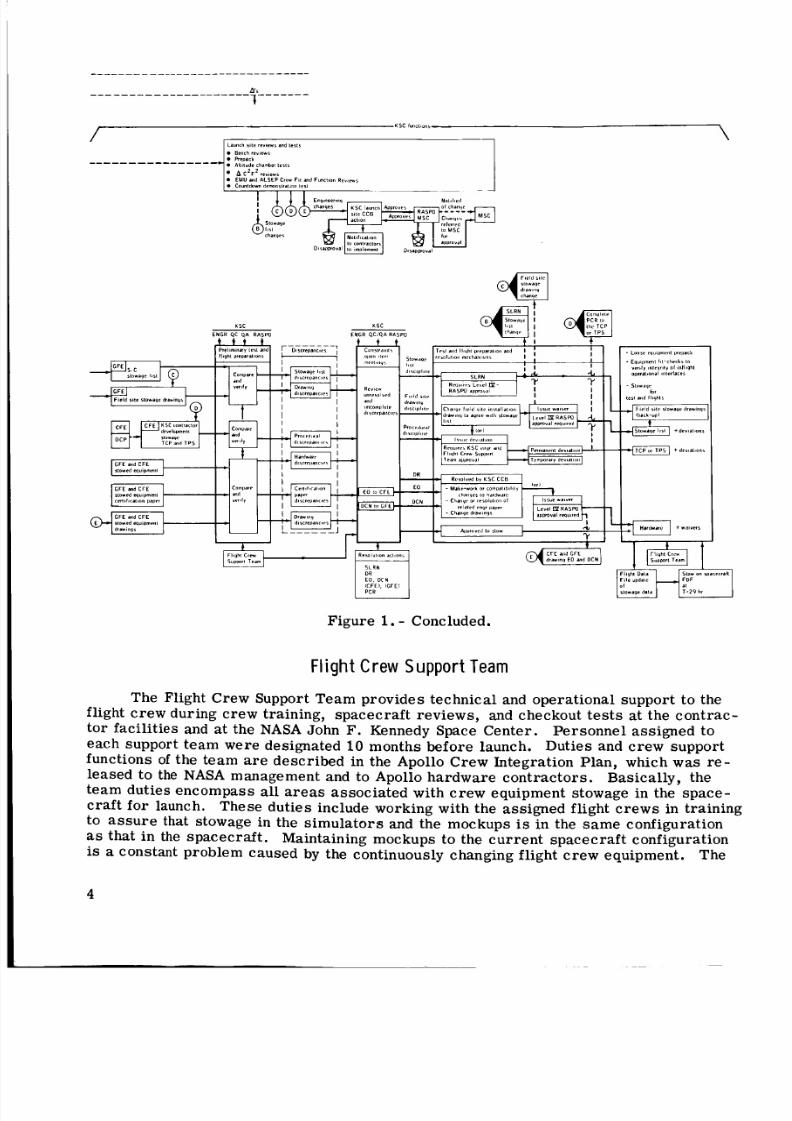
Control and stowage of the crew equipment became full-time tasks. Controlledareas fo r maintaining cr ew equipment wer e developed, and flight equipment inspection
and documentation became a major tas k in quality control functions (fig. 1 ).
To successfully manage and ensure that spacecraft crew equipment supported theoperational phase of s pace flights, the crew station team support concept wa s imple-mented at the beginning of t he Gemini P ro gr am and wa s expanded fo r the ApolloProgram.
2

8/8/2019 Apollo Experience Report Crew Station Integration Volume IV Stowage and Support Team Concept
http://slidepdf.com/reader/full/apollo-experience-report-crew-station-integration-volume-iv-stowage-and-support 9/30
SLRN
9
IIII
II
IIIIII!
IIIIIIIIII
II
Figure 1. - The NASA stowage process.
3
8/8/2019 Apollo Experience Report Crew Station Integration Volume IV Stowage and Support Team Concept
http://slidepdf.com/reader/full/apollo-experience-report-crew-station-integration-volume-iv-stowage-and-support 10/30
Figure 1. - Concluded.
Flight Crew SupportTeam
The Flight Crew Support Team provides technical and operational support to theflight crew during crew training, spacecr aft reviews, and checkout tests at the contrac-
tor facilities and at the NASA John F. Kennedy Space Cente r. Per son nel assig ned t oeach support team we re designated 10 months befor e launch. Duties and cr ew supportfunctions of the team are described in the Apollo Crew Integration Plan, which was re -leased to the NASA management and to Apollo har dwa re co ntr act ors . Basically, theteam duties encompass al l areas associated with cr ew equipment stowage in the space-cra ft fo r launch. These duties include working with the assigned flight cr ews in trainingto assure that stowage in the sim ul at or s and the mockups is in the sa me configurationas that in the spacecraft. Maintaining mockups to the curr ent spacec raft configurationis a constant problem caused by the continuously changing flight crew equipment. The
4

8/8/2019 Apollo Experience Report Crew Station Integration Volume IV Stowage and Support Team Concept
http://slidepdf.com/reader/full/apollo-experience-report-crew-station-integration-volume-iv-stowage-and-support 11/30
team member who is fam il iar with the s pacecra ft configuration provides consultation tothe crewmen as they prac tic e the ta sk s of unstowing equipment in orbi t and restowingfor entry. These tasks are practiced in authentic mockups in the sa me sequence asplanned fo r flight. To fur ther a ss ur e successfu l launch o r retu rn stowage, includingtemporary s t owage, the team coordi nates flight -hard war e -to- spac ec af t interface fit
checks. Fur the rmo re, the te am provides liaison among the flight cre ws, the ApolloSpacecraft Program Office, and othe r groups associated with crew traini ng and cr ewparticipation in spacecraft checkout. Launch day prepar ation for the crew, up t o thet ime of cre w insertion into the spacecraft, is handled by the Flight Crew Support Team.
ApolloC o u c h a n d C r e w R e s t r a i n t s
The design criteria used for the Apollo command module couch and res tr ai nt sys -tem relat ive t o crew equipment stowage were as follows.
1. To provide crew rest rai nt in the corr ect position for al l mission phases
2 . To allow perfo rmance of mi ssion-required cr ew activities, including stowingthe tunnel probe , hatch, and drogue ; donning the portable life support system (PLSS)for extra vehicul ar activity (EVA); perfo rming an EVA through the si de hatch; and oper -ating the guidance and cont rol console
3 . To allow ac cess t o all cr ew station contr ol panels and stowed equipment
To satis fy the design cri ter ia, the center couch was constructed S O that it couldbe folded out of the way and could allow the cr ewmen to move about and per fo rm va ri ousactivities, such as those previously discussed.
The couches were designed pr imari ly to accommodate three suited crewmendurin g ent ry. Difficulty was encountered during entry, when crew men we re unsuited,because the heel-clip half of th e foot re st ra in t wa s in the suit boot heel. Th is p rode mwas solved with heel clips that the crewman could st ra p on, much like sand als withmet al heels. Thes e heel cli ps wer e stowed fo r launch and then unstowed for entr y.Additionally, the hea dre st was designed prim arily to support the helmet of t he suitedcrewman during entry . The headrest problem was solved f o r the unsuited crewman byheadrest pads that could be stowed for launch and instal led before entry .
Stowage-Ar rangement Exper ience
During Pro ject Mercury and the Gemini Pro gram , experience was gained in cre wstation concepts in te r ms of modular stowage, frequency of cr ew equipment use, zer o-ghandling procedures, and inter face control of equipment. The us e of Velc ro houks,bonded to loose equipment and mated to bonded Velcr o pile i n the spacecr aft, wa sdevised fo r temp orary inflight stowage during Project Mercur y a nd continued to beused in subsequent progra ms. The Gemini Pro gra m was the first in which the con-cept of modula r c ontain er stowage was used, and the concept was applied mor e ex-tensively in the Apollo Progra m. Thi s concept involved standardized containers o rboxes filled with a plastic-foam material molded to fi t the contour s of th e it em sstowed within the container.
5

8/8/2019 Apollo Experience Report Crew Station Integration Volume IV Stowage and Support Team Concept
http://slidepdf.com/reader/full/apollo-experience-report-crew-station-integration-volume-iv-stowage-and-support 12/30
Two dist inct advantages were rea liz ed with the adoption of t hi s stowage concept.First, standardized containers with different int eri ors made it possible to use the sam ebasic stowage arr ange men ts f o r widely varying mission requi remen ts. When missionrequirements changed, only the inte rio r container in se rt s had t o be changed to acco m-modate the new stowage arr angement. Second, s pace cra ft checkout serial t imerequired fo r prelaunch stowage was reduced great ly because equipment could be pre-
packed in controlled areas away from the spacecraft.
CREWEQUlPMENTSOURCES
Equipment stowed on board the spacecraft was serialized for tracking purposesand was categorized. The cat egor ies we re Government-furnished equipment (GFE),contractor-furnished equipment (CFE), and experimental equipment.
Gover nmen t-Fu r ni shed Equip men t
Government-furnished equipment is defined as equipment supplied by the Govern-ment. Some equipment supplied by the Government is manufactured in Government-owned-and-operated shops ; however, th is type of supplied equipment is kept to aminimum to avoid the connotation of a competitive busine ss enter prise . Most GFE ispurchased from selected contr actor s on a competitive basis. After delivery of GF E tothe NASA, the hardware is processed for spacecraft installation or stowage, as de-scribed in figure l .
Contractor -F ur ni shed Equipment
Contractor-furnished equipment is defined as equipment supplied by a spacecraftcontractor. This equipment may be manufactured in contra ctor shops or purchasedthrough a vendor. Where circu mstanc es dictated, the contr actor wa s given direc tionsfrom NASA to purchase CFE f rom a specific vendor when a certain item was commonto both the command and se rv ic e module (CSM) and the lunar module (LM).
Experiment Equipment
Most scientific experimental equipment is built or purchased by the Governmentand could be classified as GFE. Although th is expe ri men t equipment is not placed onboard to support the crew, the crew must deploy the equipment to per form theexperiments.
SPACECRAFTMOCKUPS
The quantity of changes o r modifi cations in cre w equipment led to real- tim e prob-lems in spacecraft fi t toler ances and spacec raft environmental compatibility. Crewmenwer e provided with additional traini ng aids f or fam iliarization with existing hardware
6

8/8/2019 Apollo Experience Report Crew Station Integration Volume IV Stowage and Support Team Concept
http://slidepdf.com/reader/full/apollo-experience-report-crew-station-integration-volume-iv-stowage-and-support 13/30
stowage locati ons and updates to hardwar e changes. The problem of as sur ing that themockups wer e up to date with the changing hardware was solved by dir ect ing the modulecont rac tor to provide modification ki ts fo r the mockups. The modification kits wereflight-production units identical to those t o be used f or the fli ght module installation.
Consequently, spacecraft mockups became a necessary, expedient tool in det er-mining the be st use of the available spac ecra ft stowage volume. These mockups pro-vided the flight cr ew s with a quick, ready re ference to pending changes and a completespacecraft-interior-configuration likeness for training with cr ew equipment and f o rexperiment equipment handling.
TOP STOWAGE DRAWINGS
Crew equipment stowage orientation inside a volume within a spacecraf t has be-come a contro lled sequence. When one group of people stows equipment a certai n way
in the mockup and anothe r group of people stows the equipment different ly in the space-craft, confusion concerning crew equipment location and usage in flight res ult s.
Beca use of the l arge quantity of c re w equipment, the top stowage drawings we redeveloped and have become mandatory to aid in the prop er stowage of equipment. Thespacecraft stowage drawings consist of a to p assembly drawing divided into four maincategories: a listing of all the loose crew equipment (defined as that cr ew equipmentwhich can be removed , without tools, fr om one location and placed in anot her locationby a crewman); three-dimensional views of the crew equipment arrangement in a modu-la r container; three-dimensional views of th e crew equipment arr ange ment within aspac ecr aft cr ew station volume; and modular container location within the spacecra ft.
MODULAR STOWAGE
Modular container stowage has been proved to be the best method of handlingcr ew equipment fo r installation into the flight spacecr aft. However, some areas ofthe spacecraft are not suitable fo r the use of a modular cont ainer, and not all the crewequipment ca n be stowed in a modular container. For instance, the lunar-boot over-shoes are large and dimensionally unsuitable to be stowed ili thi s manner.
7
8/8/2019 Apollo Experience Report Crew Station Integration Volume IV Stowage and Support Team Concept
http://slidepdf.com/reader/full/apollo-experience-report-crew-station-integration-volume-iv-stowage-and-support 14/30
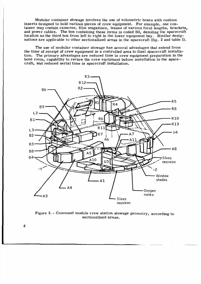
Modular container stowage involves the use of vo lumetr ic boxes with cushionin se rt s designed to hold vari ous pi eces of cre w equipment. For example, one con-tai ner may contain cam er as, film magazines, lens es of variou s foc al lengths, brac kets ,and power cables. The box containing these it em s is coded B3, denoting the spacecraf tlocation as the third box from left to right in the lower equipment bay. Simil ar desig-nations are applicable to other sectionalized areas in the spacecraft (fig. 2 and table I) .
The use of modu lar container stowage has sev er al advantages that extend fro mthe tim e of re ceipt of c rew equipment in a controlled area to final spacecraft installa-tion. The pri mary advantages are reduced time in crew equipment preparation in thebond room, capability to review the crew equipment before installat ion in the space-craft, and reduced serial time in spacecraft installation.
masks
restraint
Figure 2. - Command module cre w stati on stowage geometr y, accordi ng tosectionalized areas.
8
8/8/2019 Apollo Experience Report Crew Station Integration Volume IV Stowage and Support Team Concept
http://slidepdf.com/reader/full/apollo-experience-report-crew-station-integration-volume-iv-stowage-and-support 15/30
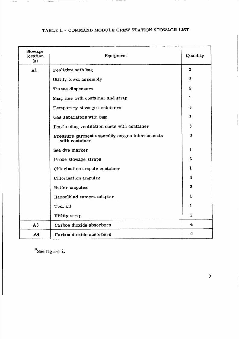
TABLE I. - COMMAND MODULE CREW STATION STOWAGE LIST
Stowagelocation
(4- 1
A3
A4
Equipment
Penlig hts with bag
Utility towel assembly
Tissue dispensers
Snag line with contai ner and str ap
Temporar y stowage containers
Gas sep ara tor s with bag
Postlanding ventilation ducts with container
Pr es su re garment assembly oxygen interconnectswith container
Sea dye ma rk er
Probe stowage str aps
Chlorination ampule contai ner
Chlorination ampules
Buff e r ampules
Hasselblad camer a adapter
Tool kit
Utility strap
Carbon dioxide absorbers
Carbon dioxide absorbers
Quantity
2
3
5
1
3
2
3
3
1
2
1
4
3
1
1
1
4
4
a See figur e 2.
9

8/8/2019 Apollo Experience Report Crew Station Integration Volume IV Stowage and Support Team Concept
http://slidepdf.com/reader/full/apollo-experience-report-crew-station-integration-volume-iv-stowage-and-support 16/30
TABLE I. - COMMAND MODULE CREW STATION STOWAGE LIST - Continued
Stowagelocation
(a>
A5
A6
A 7
A8
Equipment
Headrest pads
Heel restrai nts
Sleep restraint ropes
Sextant adapter fo r 16-mm ca mer a
Spot me t e r
Two-speed timer
Carbon dioxide absorbers
Television monitor with cable and strap
12-foot television cable with strap
Television-camera bracket
Television color c am er a with zoom lens
Television ringsight
Liquid-cooled garments
Fecal containment system
Extravehicular mobility unit maintenance kit
Pilot preference kits
Inflight exerciser
Lightweight headsets (two with ear mol d installation)
Relief receptacle in container with s tr ap s
Constant-wear-garment GFE ad apt ers in bag
Quantity
3
3 pai r
5
1
1
1
1
1
See figure 2.
10

8/8/2019 Apollo Experience Report Crew Station Integration Volume IV Stowage and Support Team Concept
http://slidepdf.com/reader/full/apollo-experience-report-crew-station-integration-volume-iv-stowage-and-support 17/30
TABLE I. - COMMAND MODULE CREW STATION STOWAGE LIST - Continued
Stowagelocation
(a>
A8
A10
A 11
B1
B2
B3
Equipment
Tissue dispensers
Constant-wear garments
Decontamination bags
70-mm magazines in bag
S-158 ex perim ental assembly:
70-mm electric Hasselblads
70-mm magazines
Photar filters - blue, red , orange, and 87C
Intervalometer
Came ra mount
50-mm lensRemote-control cable
70-mm camera-bracket assembly
Food and hygiene equipment
16-mm magazines i n bag
18-mm lens
16-mm power cable with strap
Right- angle mi rr or
5-mm l ens with cover
Quantity
2
3
7
2
4
7
1 each
1
1
1
4
See figure 2.
11

8/8/2019 Apollo Experience Report Crew Station Integration Volume IV Stowage and Support Team Concept
http://slidepdf.com/reader/full/apollo-experience-report-crew-station-integration-volume-iv-stowage-and-support 18/30
TABLE I. - COMMAND MODULE CREW STATION STOWAGE LIST - Continued
~
Equipment
75-mm lens
16-mm data acquisition camera with magazineinstalled
70-mm electric Hasselblad with 80-mm lensand magazine installed
Chlorination ampules
Buffer ampules
Chlorination needle
Chlorination syringe casing
Chlorination s yring e knob
Chlorination- equipment containe r
Carbon dioxide abs or be rs
Carbon dioxide abso rb er s
Chlorination ampul e s
Buffer ampules
Chlorination-ampule container
Voice r eco rde r with battery and tape ca sse tte
16-mm magazines
Electrostatic ground cable
Adapter tool E with strap
Quantity
4
4
1
5
1
1
See figure 2.
1 2
8/8/2019 Apollo Experience Report Crew Station Integration Volume IV Stowage and Support Team Concept
http://slidepdf.com/reader/full/apollo-experience-report-crew-station-integration-volume-iv-stowage-and-support 19/30
TABLE I. - COMMAND MODULE CREW STATION STOWAGE LIST - Continued
Stowagelocation
R3
R4
Equipment~~
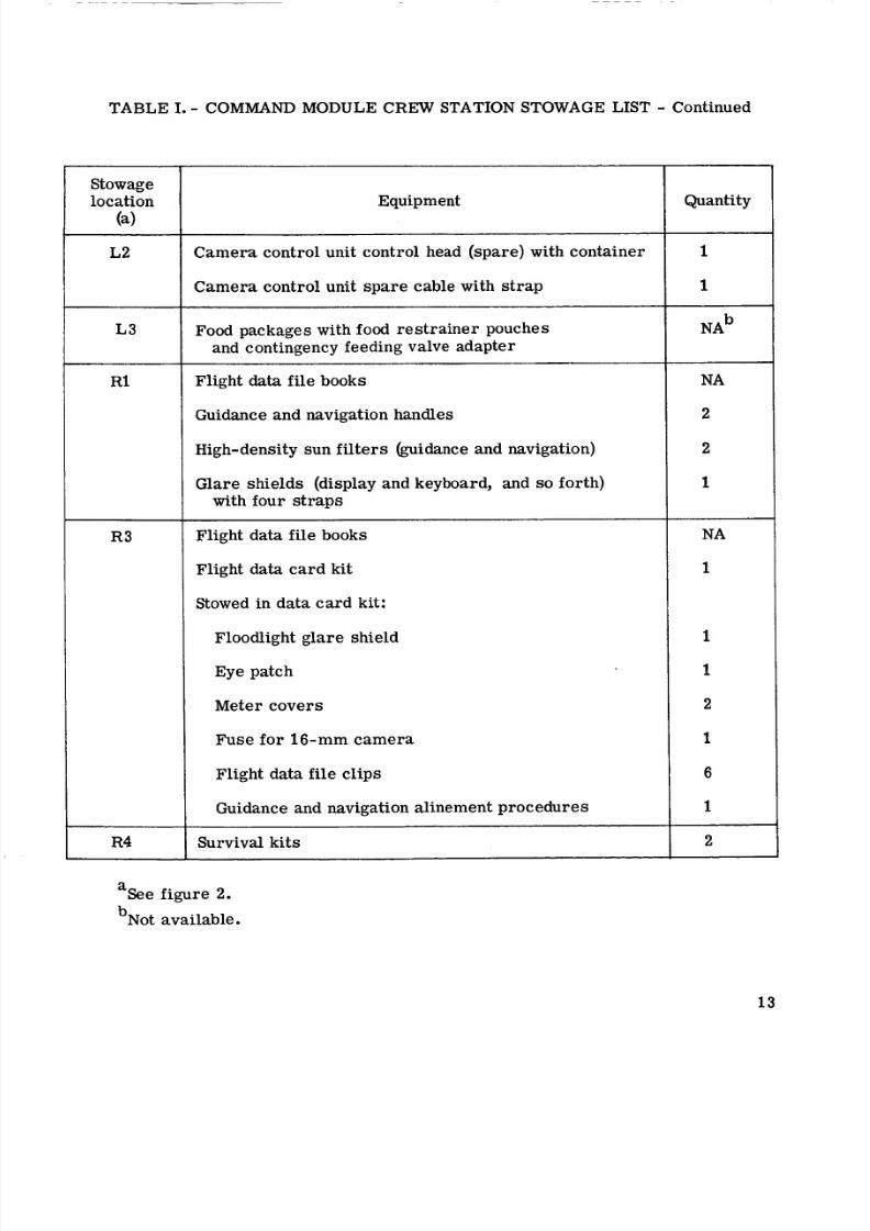
Ca me ra control unit control head (spare ) with container
Came ra control unit sp are cable with st ra p
Food packages with food rest ra in er pouchesand contingency feeding valve adapte r
Flight data file books
Guidance and navigation handles
High-density sun filters (guidance and navigation)
Glare shi elds (display and keyboard, and so forth)with four straps
Flight data file books
Flight data card ki t
Stowed in data card kit:
Floodlight glare shield
Eye patch
Meter cove rs
Fuse for 1 6 - m m camera
Flight data file clips
Guidance and navigation alinement pro ced ure s
Survival kits
Quantity
1
1
N A ~
NA
2
2
1
NA
1
1
1
2
1
6
1
2
See figure 2.
bNot available.
13

8/8/2019 Apollo Experience Report Crew Station Integration Volume IV Stowage and Support Team Concept
http://slidepdf.com/reader/full/apollo-experience-report-crew-station-integration-volume-iv-stowage-and-support 20/30
TABLE I. - COMMAND MODULE CREW STATION STOWAGE LIST - Continued
Stowagelocation
( 4
R5
R6
R8
R11
Equipment
G a s and liquid waste management syst em quick-disconnect filter assemblies
Inflight retainer straps
Back-to-back straps
Helmet bags
Accessory bags
Tape
Cabin vent quick-di sconnect
Medical kit (with urine collection transfer assemblyroll-ons)
Fecal collection assemblies
Sanitation supply box (aft)
Sanitation supply box (forward)
Coupling ass embl y water panel
Water panel quick- disconnec t
Waste management syst em pre ss ur e cap quick-disconnect
Waste management system power cable
Roll-on cuffs (red, white, blue)
Urine tr ans fe r system s with roll-ons
Urine receiver (spare)
Quantity
1
30
1
1
1
1
1
1
1 pack-ageeach
3
1
1 4
"See figure 2.

8/8/2019 Apollo Experience Report Crew Station Integration Volume IV Stowage and Support Team Concept
http://slidepdf.com/reader/full/apollo-experience-report-crew-station-integration-volume-iv-stowage-and-support 21/30
TABLE I. - COMMAND MODULE CREW STATION STOWAGE LIST - Continued
Stowage
location(a)
Guidance andnavigationpanel, lowerequipment bay
Aft bulkhead,under A6
On came ra controlunit
On upper equip-ment bayoxygen repr es -surizationsystem
On side of A3
Above left-handwindow
In environmentalcontrol unit
Oxygen repres-surization
Aft upper equip-ment bay
R12
Equipment
Radiation survey meter
Urin e Hose ass emb ly with container
Inflight retainer strap
Urine collection transfer assemblytransfer adapter
Camera control unit control heads
Shades with conta iner
Fire extinguisher
Crew optical alinement sight with bulb
Carbon dioxide absorbers
Oxygen mask and hose with utility
Rest restraints Oeft, right, and cente r)
st ra ps and container
Flight data file books
Quantity
1
1
1
1
3
5
1
1
2
3
3
NA
a See figure 2.
15

8/8/2019 Apollo Experience Report Crew Station Integration Volume IV Stowage and Support Team Concept
http://slidepdf.com/reader/full/apollo-experience-report-crew-station-integration-volume-iv-stowage-and-support 22/30
TABLE I. - COMMAND MODULE CREW STATION STOWAGE LIST - Continued
Stowagelocation
(a>~~
R13
u3
Under left-handcouch
I
Equipment
~~~~ ~ ~
16-mm magazines in bag
Passive dosimeter (in. 16-mm magazine bag)
70-mm magazines in bag
70-mm magaz ines in bag
Jettison stowage bag
Docking targe t adapte r
16-mm ca mera bracket
LM docking target
Crew optical alineme nt sight light bulbs
C r e w optical alinement sight filter
Tape recorder casse t tes
Recorder battery packs
Monocular
Intervalometer
250-mm lens
Forward hatch container
Quantity
1iSee figure 2.
16

8/8/2019 Apollo Experience Report Crew Station Integration Volume IV Stowage and Support Team Concept
http://slidepdf.com/reader/full/apollo-experience-report-crew-station-integration-volume-iv-stowage-and-support 23/30
TABLE I. - COMMAND MODULE CREW STATION STOWAGE LIST - Concluded
Stowagelocation( 4
In pressure garmentassembly bagunder centercouch
On guidance andnavigation panel
On B5 and B6
Under A3
Side of A8
Right and left lowerequipment bay
Closeout curtainpockets, inpouches
On B1 door~~
On translational
and rotationalhand controllers
Equipment
Urine collection transfer assembly clamps
Oxygen screen clamps
Couch straps
Pr es su re garment assembly electrical con-nector cover s
HeIme shie Id
Ver b and noun list (guidance and navigation)
Closeout curtains, B-5 and B-6
Acoustic tone booster in bag
Vacuum brus hes in bag
Vacuum hose i n bagCalfax adapter plate assembli es, right and
left
Data retention snap assembli es, hook ass em-blies, snap clamps, and spring cli ps
~~ ~
Snap adap ter s, food compar tment
Harness s tr aps
Quantity
1
1 each
2 each
NA
6
3
aSee figure 2.
17
8/8/2019 Apollo Experience Report Crew Station Integration Volume IV Stowage and Support Team Concept
http://slidepdf.com/reader/full/apollo-experience-report-crew-station-integration-volume-iv-stowage-and-support 24/30

8/8/2019 Apollo Experience Report Crew Station Integration Volume IV Stowage and Support Team Concept
http://slidepdf.com/reader/full/apollo-experience-report-crew-station-integration-volume-iv-stowage-and-support 25/30
verify that no damage to the equipment ha s occurred during transport; placement of themodule into the prefitted, checked location; an d secure men t of the module with pip pinso r Calfax fasteners.
FREQUENCYOF CREWEQUlPMENT USE
Just as in any airc ra ft cockpit that has provisions for stowed equipment, somea r e a s in a spacecraft are mor e acces sible than others. Because of pre ssu re- sui t bulkand the ze ro -g environment, pr ime consideration is given to allocating high-use crewequipment to the most acces sible locations and low-use equipment to the le ast a cc es s-ible a re a s . Food and ca me ra equipment a r e examples of cr ew equipmelit that occupythe most acces sible locations in the stowage wra nge men t. Equipment that i s usedperiodically or that can be retrie ved with minimum effort c an be categorized as secon-da ry stowed equipment. A gene ralized ma tr ix of stowed crew equipment could beclassified as follows.
P r imary
Food
P e r sonal-hygieneequipment
Came ras andequipment
Secondary
Medical kit
Lithium hydroxidecar t r idges
Tethers
Te r iarv
Survival kits
EVA equipment
Tool kits
Flight data file
ZERO-GRAVITY HAN DLING PROCEDURES
The na tu ra l law of physics, ". . to each action th ere is an equal and oppositereaction, " is very pronounced and applicable in ze ro g. h i d e the spacec ra ft , thecrewmen use strategically located handholds t o aid in their maneuverability. Pri ma ryand secondary stowage of equipment is justified furt he r on the ba si s of limiting bodymaneuvers needed for retrieval.
Temp ora ry retention methods that satisfy the temporary stowage requirementshave been developed, t rie d, and proved. Four different methods have been used fo rte mp or ar y retention of high-use cr ew equipment. These are Velcro, metal snaps,utility straps, and bungee cords.
1 9

8/8/2019 Apollo Experience Report Crew Station Integration Volume IV Stowage and Support Team Concept
http://slidepdf.com/reader/full/apollo-experience-report-crew-station-integration-volume-iv-stowage-and-support 26/30
Ve l c r o
Velcro has proved to be a very effective general-purpose tempor ary retentiondevice and was used as the only retention device in Project Mercury and the GeminiProgram. Patches of Velc ro hook wer e bonded to areas on spacec raft bulkheads con-veniently within re ac h of the crewmen. Small patches of Velcro pile we re bonded tothe crew equipment. The mating of Velc ro pile to Velcro hook provided the nec es sa ryretention and ease of retrieval as the equipment was used.
However, the Velcro w a s made of nylon and had a high burn rate. After theApollo fire, a new Velcro ma ter ial w as developed that was less combustible but l e s seffective. Consequently, the use of Velcro became limi ted and oth er methods ofretention w ere investigated.
Metal Snaps
Metal snaps have become second to Velcr o in frequency of usage f or equipmentretention. The snaps are nonflammable and have become the pri me method fo r re ten -tion of deb ris gu ard s and container flap s throughout the space craft. One side of a snap,either male o r female, must be mounted to a hard surface in the spacecraft. Snapsal so ar e used to secu re co ve rs on Beta-cloth bags, in which the male portion of thesnap is attached to a hard surface. Apollo flight cre ws have found that separa tion ofsoft-backed snaps is very difficult to perform while in space suits and in a zero-genvironment .
The two types of snaps in space cra ft use are unidirectional and omnidirectional.Unidirectional snap s are used when the holding requirement is subjected t o the forc esof lift-off and landing. These snap s are designed s o that when the two portions are
mated, the force acting on the snap cannot sep ara te them. However, if separationforces are applied on the opposite side from the acting forces, the mating snaps re -lease easily. Omnidirectional snaps are separated easily and are used to hold againstlight forces , mostly by she ar. This is the type of sn ap used to hold the s pacec raft d e-bris guards.
UtilityStraps
Utility s tr ap s were developed to supplement the limited amount of Velc ro placedin the spacecraft. These s trap s were approximately 1 2 inches long, with mating snapsand a tab of Velcro pile at each end. This configuration enabled the st ra p to be snapped
around a handhold o r on another sn ap within the spa cec raf t, and the Velcr o at the oppo-site end was used t o retain cr ew equipment.
Bungee Cords
Bungee-cord retention is the newest technique used for temporary stowage ofcre w equipment in ze ro g. Bungee co rd s we re suggested by the Apollo 10 cre w andwere carried on the Apollo 11 and subsequent mis sio ns. Bungee co rd s are metal
20
8/8/2019 Apollo Experience Report Crew Station Integration Volume IV Stowage and Support Team Concept
http://slidepdf.com/reader/full/apollo-experience-report-crew-station-integration-volume-iv-stowage-and-support 27/30
"scre en door" spr ing s with sna ps attached to each end. These bungee co rd s are slight-ly stretch ed betweer. mating snaps, strat egical ly located in the crew compartment.Thi s method provides a retention scheme whereby loose items such as gloves, foodpacks, books, and pens may be pr es sed behind the expanded spring. The use of bungeecords has proved to be the best supplement to Velcro fo r loose equipment in the
spacecraft.
INTERFACECONTROL
The interfa ce cont rol of cr ew equipment is the biggest task t o accomplish in cre wstation stowage arra ngemen t. Interface cont rol of equipment becom es ver y involvedwhen sever al different contra ctors are selected to provide cre w equipment. Eac hsource must be fami liar with the interface t o which that equipment must f i t for thecrew station stowage arrangement to integrate all equipment into the spacecraft.Further emphasis is placed on cre w equipment serialization. The seri alize d equipmentis fi t checked to the launch and in-use configuration to ass ur e that inte rfac e contro lha s not been violated and that dimensional probl ems have been solved. After a serial-ized piece of equipment is f i t checked, it is documented and assigned to the respectivespacecraft. Principally, interface control becomes necessa ry between flight cr ew sand crew equipment, flight crews and spacecraft, crew equipment and spacecraft, andspacecr aft and spacecraf t.
FI ght -C rew- o-C rew-Equipm en In e r a ce
The int erfac e between flight cre w and crew equipment is the mo st difficult tocontrol. Probably the most difficult item of crew equipment to f i t is the su i t . Obvious-ly, the el emen t of human feel ing and com for t is a prime factor in achieving peak opera-tional performance. Other fac tor s are the suit and crewm an mobility and operationalefficiency that are affected by the PLSS, penlight, pens, and ot he r equipment . Mobility,comfort, and operational efficiency cannot be measur ed by volume o r width and depth.This interface can be controlled only by the individual to whom the equipment has beenfitted.
FIigh -C rew-to-S pacecr af tI n e r a ce
Two design r eviews (milestones) have been implemented, in phase 11 of the ApolloPr og ra m and in the Skylab Progr am, f o r prim ary stowage design and identification offlight cre w inter face problems with spacecraft hardware. These reviews are th e Pre-liminary Design Review (PDR) and the Critical Design Review (CDR).
The PDR is concerned with the contr actor sketch es in t e r m s of proposed stowageconcepts and methods of crew equipment ret ri eval and use. The NASA cr ew repr esen t-ative s fam ili ar with stowage concepts and crew station arrangem ents review the stow-age s ket che s and propose changes to drawings and concepts.
The CDR is the fin al contr actor -dra wing review with NASA repr esen tat ive s be-for e drawing release. After drawing release, manufacturing and flight-hardw are
21

8/8/2019 Apollo Experience Report Crew Station Integration Volume IV Stowage and Support Team Concept
http://slidepdf.com/reader/full/apollo-experience-report-crew-station-integration-volume-iv-stowage-and-support 28/30
production is begun. Verification of the stowage design and redesi gn (o r both) usuallyis performed i n the contractor-facility mockup by a NASA flight crew and then again inthe actual spacecraft.
C rew-Equ p m e n -to-Spacecr af tI n e r ace
Experience has shown that control of the crew-equipment-to-spac ecraft int erf aceis a very difficult task . Of the cr ew equipment it em s flown, a sma ll percentage wasmanufactured by the space craft contr actor . Theref ore, it was necessary to implementa contractual document, known as an interface control drawing (ICD), that de scr ibe san agreemen t among al l participating parti es (that is, spacecraft contractor, crewequipment contr actor , and NASA). The drawing s we re signed by al l parti es, and thecrew equipment was designed within the basic criteria se t forth in these drawings. Fo rexample, a dimensiona l drawin g of the PLSS is submitted by the crew equipment con-tractor for NASA approval. The spacecraf t contracto r must approve the ICD becausethe PLSS int erf ace s with stowage provisions in the LM. The suit manufact urer mustapprove the ICD because the PLSS attac hes to the crewm an space suit. The NASA must
approve the ICD because the crewman must fly the spacecraft, wear the s uit, wear thePLSS, and re ly on the PLSS or life support. Obviously, any sma ll change in detai l inany one of the points of inter face could affect the f i t and function of the equipment.Therefore, all concerned must agree on a change before it can be implemented.
After the flight hardware had been manufactured and serialized, it is fit checkedto its respective in-use position in the space craft. These checks elimin ate the misfit sthat sometimes occur because of tolerance buildup or dimensional er ro r s .
Spacecraf t - to-Spacecraf t In ter face
Some crew equipment is stowed in the LM at earth launch, then transferred intothe command module (CM) before lunar -orbi t separ ation . One example of the inte r-changeability requirements is the requ iremen t fo r interchanging the lunar -rock boxeswith the CM lithium hydroxide boxes. Th is interchange re qu ir es that the ICD be agreedon by both space cra ft cont rac tor s and NASA.
CONCLUDINGREMARKS
Experience with crew equipment and cr ew station stowage arra ngemen ts empha-si ze s the necessity fo r minimal crew effort in retrievi ng and using crew equipment inze ro g. It is desirable to do a s many one-handed operations as possible in ze ro g.Thi s procedure leave s one hand free to g ra sp handholds and to counteract body torqu esgenerated by removing, replacing, o r using ce rta in cr ew equipment.
Rigid contr ol of c rew equipment, both fo r in ter fac e fits and fo r functional relia-bility, is neces sary. The cos t pe r pound of placing equipment in ea rt h orbit and beyondjustifies the effort required to assure usable c re w equipment.
2 2

8/8/2019 Apollo Experience Report Crew Station Integration Volume IV Stowage and Support Team Concept
http://slidepdf.com/reader/full/apollo-experience-report-crew-station-integration-volume-iv-stowage-and-support 29/30
The support team, in close coordination with the assigned flight crews , suppor tsall operational phas es of space fligh ts with r espe ct to management of cr ew equipment,including astronaut trai ning in c rew equipment stowage and usage.
Spacecraft mockups and crew equipment mockups are required early in a manned
spacecr aft program to develop crew equipment familiarity and handling procedures be-for e final flight-hardware delivery, The most important lesson learned concerningflight crew equipment is the need fo r earl y definition of requi remen ts and for the timelydelivery of hardware on a schedule compatible with the s pacecr aft -testing sequence.
Lyndon B. Johnson Space CenterNational Aeronautics and Space Administration
Houston, Tex as 77058, Ju ly 2, 1973995-40-21-S1-72
NASA-Langley, 1973
-1 S-364 23

8/8/2019 Apollo Experience Report Crew Station Integration Volume IV Stowage and Support Team Concept
http://slidepdf.com/reader/full/apollo-experience-report-crew-station-integration-volume-iv-stowage-and-support 30/30
AT I O N A L A E R O N A U T I CS A N D S PA C E A D M I N I S T R AT I O N
WA S H I N G TO N . D . C . 2 0 5 4 6POSTAGE AND FEES PA I D
NATIONAL AERONAUTICS ANDOFFICIAL B U S I N E S S SPACE ADMINISTRATION
PENALTY FOR PRIVATE US E 8 3 0 0 SPECIAL FOURTH-CLASS RATE 4 5 1 USMAIL
BOOK
: If Undellverable (Section 158Powtnl Nnnunl) Do Not Return
‘T h e aeronautical and space activities of the United States shall beconducted so as t o contribute . . . o the expansion of human knowl-edge of phenomena in the atmosphere and space. The Administrationshall juovide for the widest practicable and approprkte disseminationof infor ma tion concerning its activities and the results thereof.”
-NATIONAL AERONAUTICSA ND SPACE ACT O F 1958
NASA SCIENTIFIC AND TECHNICAL PUBLICATIONS
TECHNICAL REPORTS: Scientific andtechnical information considered important,
complete, and a lasting contribution to existingknowledge.
TECHN ICAL NOTES: Information less broadin scope but nevertheless of importance as acontribution to existing knowledge.
TECHNICAL MEMORANDUM SInformation receiving limited distributionbecause of preliminary data, security classifica-tion, or other reasons. Also includes conferenceproceedings with either limitedor unlimiteddistribution.
CONTRACTOR REPORTS: Scientific andtechnical information generated under a NASAcontract or grant and considered an importantcontribution to existing knowledge.
TECHNICAL TRANSLATIONS: Informationpublished in a foreign language considered
to merit NASA distribution in English.
SPECIAL PUBLICATIONS: Informationderived from or of value to NASA activities.Publications include final reports of majorprojects, monographs, data compilations,handbooks, sourcebooks, and specialbibliographies.
TECHNOLOGY UTILIZATIONPUBLICATIONS: Information on technologyused by NASA that may be of particularinterest in comm ercial and other. non-aerospaceapplications. Publications include Tech Briefs,Technology Utilization Reports andTechnology Surveys.
Details on the availability of these publications m ay be obtained from:
SCIENTIFIC AND TECHNICAL I N F O R M AT I O N OFFICE
N A T I O N A L A E R O N AU T IC S A N D SPA C E A D M I N I S T R A T I O N