apollo 30- (a-2 or as-502/csm-020) spacecraft operational ... · launch site inertial attitude...
TRANSCRIPT

* * ., Bd/c5dAq+g&/@&/& e N A T I O N A L AERONAUTICS A N D SPACE A D M I N I S T R A T I O N
M S C INTERNAL NOTE NO. 68-FM-62
M a r c h 13, 1968
APOLLO 6 QCT 30- ( A - 2 OR AS-502 /CSM-020)
SPACECRAFT OPERATIONAL TRAJECTORY
VOLUME I -MISSION P R O F I L E
By W i l l i a m J . B e n n e t t a n d R o n n y H . M o o r e , O r b i t a l M i s s i o n A n a l y s i s B r a n c h ,
a n d J o n C . H a r p o l d , l u n a r M i s s i o n A n a l y s i s
i m a m m e a m e . . a e . a m
~ e e a a a e e a e . . e . e i
~ . e . * * a a e . e . a a e i
~ e . e * m e e - a e . * * * ~
. e . . - * - m I ........ ........ ........ ........ ........ ....... ........ ....... ........ ....... ........ .......
........ ........ I . ........
I
! MISSION P L A N N I N G A N D A N A 4
M A N N E D SPACECRAFT CENTER HOUSTON, T E X A S
. . . . . . . . . . . . . . . . . . . . . . . . . . . . . . . . . . . . . . . . . . . . . . . . . . . . . . . . . . . . . . . . . . . . . . . . . . . . . . . . . . . . . . . . . . . . . . . . . . . . . . . . .

i
MSC INTERNAL NOTE NO. 68-FM-62
PROJECT APOLLO
APOLLO 6 (A-2 OR AS-502/CSM-020)
VOLUME I - MISSION PROFILE SPACECRAFT OPERATIONAL TRAJECTORY
By William J. Bennett and Ronny H. Moore, Orbital Mission Analysis Branch, and Jon C. Harpold, Lunar Mission Analysis Branch
March 13, 1968
MISSION PLANNING AND ANALYSIS DIVISION
NATIONAL AERONAUTICS AND SPACE ADMINISTRATION
MANNED SPACECRAFT CENTER
HOUSTON, TEXAS
Approved: Edqar C. Lineberry, C W Orbital Qss ion Analysis Branch
Approved : M. P. Frank 111, Chief Lunar Mission Analysis Branch
Approv

CONTENTS
I I *
Se c t i on Page
. . . . . . . . . . . . . . 1.0 INTRODUCTION AND SUMMARY. 1
. . . . . . . . . . . . . . . . . . . . 1.1 1.1 Purpose. 1
1.2 S c o p e . . . . . . . . . . . . . . . . . . . . . . 1
1.3 Summary of Spacecraft Operat ional Tra jec tory . . 2
2.0 SUMMARY OF INPUT DATA . . . . . . . . . . . . . . . . 4
2.1 Saturn V Launch Vehicle. . . . . . . . . . . . . 4
2.2 Spacecraft (CSM-020) . . . . . . . . . . . . . . 4
2 .3 MSFN Tracking Sta t ions . . . . . . . . . . . . . 4
2.4 Spacecraf t and Att i tude Reference Coordinate System. . . . . . . . . . . . . . . . 4
2.4.1 Spacecraft body coordinate system
2.4.2 Launch s i t e i n e r t i a l a t t i t u d e re ference
2.4.3 Earth-reference r o t a t i n g a t t i t u d e co-
. . . . . . . . . . . . . . cx,, YB’ z,),. 5
system (xIY y I Y zI) 5
ord ina te system ( X R y Y R y ZR).
2.4.4 P l a t form coordinate system ( X p’ YPY z,) 5
. . . . . . . . . . . . . . . . . 5
2.4.5 Navigation base coordinate system YNB’ ZNB) . . . . . . . . . . . . . 5
2.4.6 Relat ive vehicle coordinate system ( X R V Y YRV’ ZRV) . . . . . . . . . . . . . 6
2.4.7 Spacecraf t look angles ( ( b y 8 ) . . . . . . 6
2.5 Orbital Geometry and Trajectory Pzrameter Defini t ions . . . . . . . . . . . . . . . . . . . 6
. . . . . . . . . . . . 2.5.1 Orbital geometry. 6 2.5.2 Tra jec tory parameters 7 . . . . . . . . . .
iii

Page Sect i on
8
8
8
9
10
10
. . . . . . . . . . . . . . . . . 11 3.6 First SPS Burn
3.7 Earth I n t e r s e c t i n g Coast . . . . . . . . . . . . 3.8 Second SPS Burn. . . . . . . . . . . . . . . . . 3.9 Preentry Sequence. . . . . . . . . . . . . . . . 3.10 Atmospheric Entry . . . . . . . . . . . . . . .
4.0 MISSION PROFILES RESULTING FROM SPS ENGINE FAILURE. . 16
4 . 1 F i r s t SPS Burn; No Second SPS Burn 16
16 4.2 Summary of Splash Points . . . . . . . . . . . .
3.0 NOMINAL MISSION DESCRIPTION . . . . . . . . . . . . . 3.1 Prelaunch. . . . . . . . . . . . . . . . . . . . 3.2 Saturn V Ascent t o Orbi t . . . . . . . . . . . . 3.3 Earth Parking Orbi t . . . . . . . . . . . . . . . 3.4 Second S-IVB Burn. . . . . . . . . . . . . . . . 3.5 S-IVB/CSM Separat ion . . . . . . . . . . . . . .
11
13
13
14
. . . . . . .
TRACKING AND COMMUNICATIONS DATA. . . . . . . . . . . 17
REFERENCES. . . . . . . . . . . . . . . . . . . . . . . . . . . 10 7
5.0
i v
I
FIGURES
I
F igure
1-1
2-1
2- 2
2- 3
2-4
2- 5
2-6
2-7
2-8
2- 9
2-10
2-11
3-1
3-2
3-3
3-4
Page
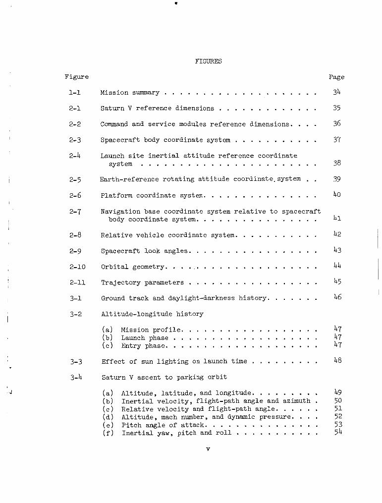
Mission summary . . . . . . . . . . . . . . . . . . . . 34
Saturn V re ference dimensions . . . . . . . . . . . . . 35
Command and se rv ice modules r e fe rence dimensions. . . . 36
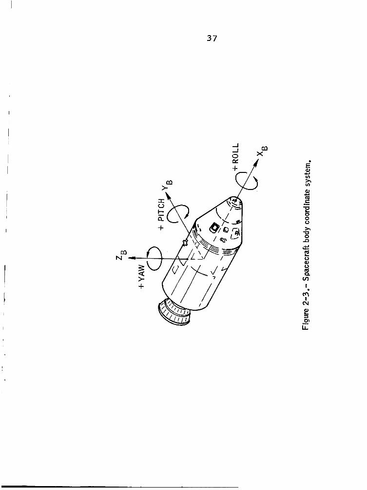
Spacecraft body coordinate system . . . . . . . . . . . 37
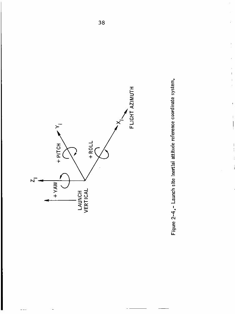
Launch s i t e i n e r t i a l a t t i t u d e re ference coordinate system . . . . . . . . . . . . . . . . . . . . . . . 38
Earth-ref erence r o t a t i n g a t t i t u d e coordinate. system . . 39
Platform coordinate system. . . . . . . . . . . . . . . 40
Navigation base coordinate system r e l a t i v e t o spacecraf t body coordinate system. . . . . . . . . . . . . . . . 41
Rela t ive v e h i c l e coordinate system. . . . . . . . . . . 42
Spacecraft look angles. . . . . . . . . . . . . . . . . 43
Orb i t a l geometry. . . . . . . . . . . . . . . . . . . . . 44
Trajec tory parameters . . . . . . . . . . . . . . . . . 45
Ground t r a c k and daylight-darkness h i s t o r y . . . . . . . 46
Alti tude-longi tude h i s t o r y
( a ) Mission p r o f i l e . . . . . . . . . . . . . . . . . . (b) Launch phase . . . . . . . . . . . . . . . . . . . ( c ) Entry phase. . . . . . . . . . . . . . . . . . . . Effec t of sun l i g h t i n g on launch time . . . . . . . . . Saturn V ascent t o parking o r b i t
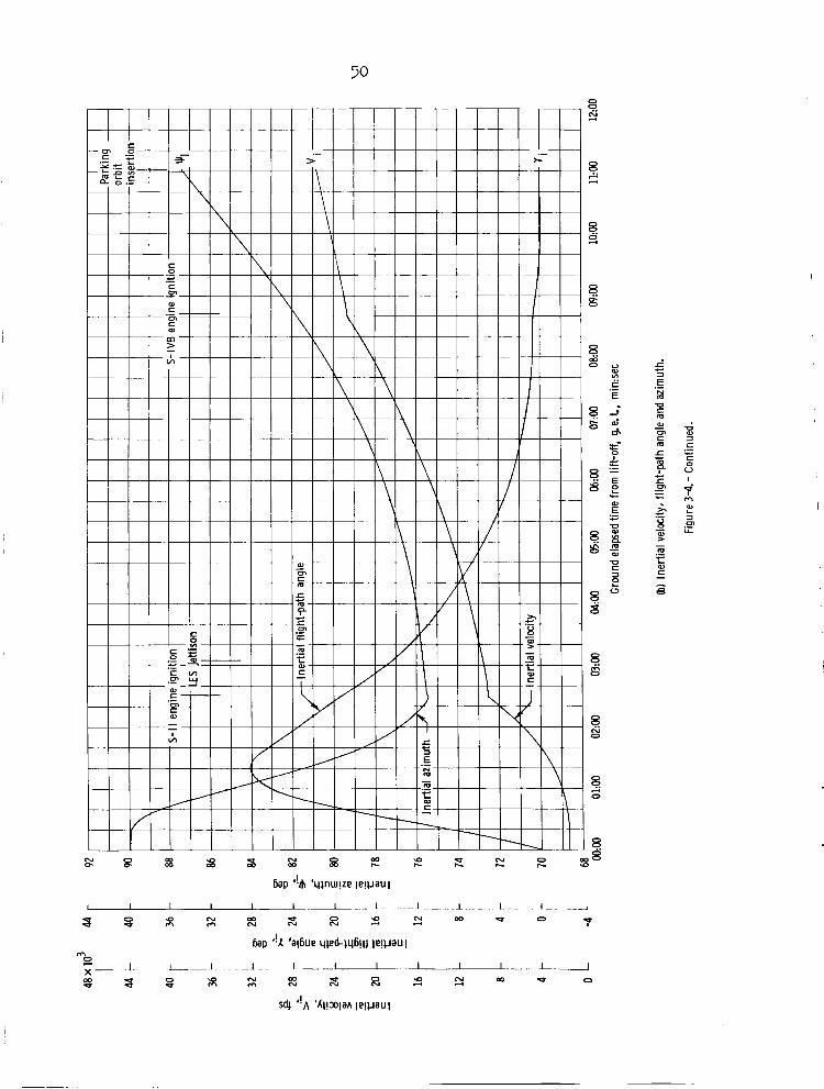
( a ) Al t i t ude , l a t i t u d e , and longi tude . . . . . . . . . ( b ) I n e r t i a l v e l o c i t y , f l i gh t -pa th angle and azimuth . ( c ) Re la t ive v e l o c i t y and f l i gh t -pa th angle . . . . . . ( d ) A l t i t ude , mach number , and dynamic pressure . . . . ( e ) P i t c h angle of a t tack. . . . . . . . . . . . . . . ( f ) I n e r t i a l yaw, p i t ch and roll . . . . . . . . . . .
47 47 47
48
49 50 5 1 52 53 54
V

Figure
3- 5 Earth parking o r b i t
( a ) Al t i t ude , l a t i t u d e and longi tude . . . . . . . . . 55
azimuth. . . . . . . . . . . . . . . . . . . . . . 56 ( c ) I n e r t i a l yaw, p i t c h , and roll. . . . . . . . . . . 57
(b ) I n e r t i a l ve loc i ty , f l igh t -pa th angle, and
3- 6 Second S-IVB burn
(a ) Al t i t ude . l a t i t u d e . and longi tude. . . . . . . . . 58 ( b )
( c ) I n e r t i a l yaw, p i t c h , and roll. . . . . . . . . . . . 60
3-7 CSM/S-IVB separa t ion c h a r a c t e r i s t i c s . . . . . . . . . . 6 1
I n e r t i a l ve loc i ty , f l igh t -pa th angle , and azimuth. . . . . . . . . . . . . . . . . . . . . . 59
3-8 Time h i s t o r y of CSM/S-IVB r e l a t i v e v e l o c i t y and separa t ion d i s t ance . . . . . . . . . . . . . . . . . 62
3-9 Spacecraft a t t i tude o r i en t a t ion requirement s during e a r t h i n t e r s e c t i n g coas t . . . . . . . . . . . . . . . 63
3-10 Effec t of launch delay on sun look angles
( a ) Primary s o l a r soak a t t i t u d e . . . . . . . . . . . . 64 ( b ) Secondary s o l a r soak a t t i t u d e . . . . . . . . . . . 65
3-11 F i r s t SPS burn
( a ) Al t i t ude , l a t i t u d e , and longi tude . . . . . . . . . 66 (b ) I n e r t i a l v e l o c i t y , f l igh t -pa th angle , and
a z i m u t h . . . . . . . . . . . . . . . . . . . . . . 67 ( c ) I n e r t i a l yaw, p i t c h , and roll. . . . . . . . . . . 68 ( d ) Rela t ive yaw, p i t c h , and roll. . . . . . . . . . . 69 ( e ) IMU gimbal angles . . . . . . . . . . . . . . . . . 70 ( f )
and f l i gh t -pa th angle a t en t ry . . . . . . . . . . 71 ( g ) Instantaneous apogee and per igee a l t i t u d e . . . . . 72
Time of f r e e f a l l t o r een t ry , p red ic ted v e l o c i t y
3-12 Earth in t e r sec t ing coast
Page
. . . . . . . . . . ( a ) Al t i tude l a t i t u d e and longi tude. 73
angle. 74 ( b ) I n e r t i a l v e l o c i t y , azimuth, and f l i gh t -pa th . . . . . . . . . . . . . . . . . . . . . .

Figure Page
Earth i n t e r s e c t i n g coast .(concluded)
( c ) I n e r t i a l yaw. p i t ch . and r o l l . . . . . . . . . . . 75
( e ) IMU gimbal angles . . . . . . . . . . . . . . . . . 77 ( d ) Rela t ive yaw. p i tch . and roll . . . . . . . . . . . 76
3-13 Second SPS burn
( a ) Al t i tude . l a t i t u d e . and longi tude . . . . . . . . . 78 ( b ) I n e r t i a l ve loc i ty . f l ight-path angle. and
azimuth . . . . . . . . . . . . . . . . . . . . . . 79 ( c ) I n e r t i a l yaw. p i t ch . and r o l l . . . . . . . . . . . 80 ( d ) Rela t ive yaw. p i t ch . and roll . . . . . . . . . . . 81
( f ) 83
( g ) Instantaneous apogee and per igee a l t i t u d e s . . . . . 84
( e ) IMU gimbal angles . . . . . . . . . . . . . . . . . 82 Time of f r e e f a l l t o reentry. p red ic ted v e l o c i t y and f l i gh t -pa th angle a t entry . . . . . . . . . . . . .
3-14 CM/SM separa t ion d i s t ance . . . . . . . . . . . . . . . . 85
3-15 Preentry sequence
( a ) Al t i tude . l a t i t u d e . and longi tude . . . . . . . . . 86 ( b ) I n e r t i a l ve loc i ty . f l igh t -pa th angle. and
azimuth . . . . . . . . . . . . . . . . . . . . . . 87
( d ) Rela t ive yaw. p i t ch . and roll . . . . . . . . . . . 89 ( e ) IMU gimbal angles . . . . . . . . . . . . . . . . . 90
( c ) I n e r t i a l yaw. p i t ch . and roll . . . . . . . . . . . 88
3-16 Spacecraft landing foo tp r in t . . . . . . . . . . . . . . 91
3-17 Reentry a l t i t u d e range p r o f i l e . . . . . . . . . . . . . 92
3-18 Atmospheric entry
(a) Heat r a t e . heat load. and load f a c t o r . . . . . . . 93 ( b ) Al t i tude . bank angle. and load f a c t o r . . . . . . . 94 ( c ) A l t i t ude . l a t i t u d e . and longi tude . . . . . . . . . 95 ( d ) I n e r t i a l ve loc i ty . f l igh t -pa th angle. and
azimuth . . . . . . . . . . . . . . . . . . . . . . 96 ( e ) Rela t ive ve loc i ty . f l igh t -pa th angle. and
azimuth . . . . . . . . . . . . . . . . . . . . . . 97 ( f ) Al t i t ude . dynamic pressure. and mach number . . . . 98 ( g ) Bank angle and t r i m angle of a t t a c k . . . . . . . . 99 ( h ) IMU gimbal angles . . . . . . . . . . . . . . . . . . 100
v i i

Figure Page
3-19 Entry communications blackout . . . . . . . . . . . . . 101
4-1 102
4-2 Summary of sp lash po in t s 10 3
Spacecraft landing f o o t p r i n t . no second SPS burn . . . . . . . . . . . . . . . . . .
5-1 Ground t r a c k and radar coverage
( a ) F i r s t r evo lu t ion . . . . . . . . . . . . . . . . . 104 ( b ) Second revolu t ion . . . . . . . . . . . . . . . . . 105 ( c ) Third r evo lu t ion . . . . . . . . . . . . . . . . . 106
v i i i

TABLES
Page Table
2- I
3- I
MSFN GROUND STATIONS AND CAPABILITIES
( a ) Unif ied S-band s t a t i o n s . . . . . . . . . . . . ( b ) C-band s t a t i o n s . . . . . . . . . . . . . . . .
APOLLO 6 MISSION DISCRETE EVENTS SUMMARY
(a ) Sa turn v opera t ions . . . . . . . . . . . . . . ( b ) Spacecraf t opera t ions . . . . . . . . . . . . .
3-11 APOLLO 6 MISSION SPACECRAFT ATTITUDE SUMMARY . . . . . 3-111 SERVICE MODULE RCS PROPELLANT EXPENDITURES . . . . . . 3-IV SUMMARY OF S-IVB ATTITUDE MANmTvERS
(a ) Ear th parking o r b i t . . . . . . . . . . . . . . (b ) Pos t i n j e c t i o n . . . . . . . . . . . . . . . .
3-v SPACECRAFT GUIDANCE TARGETING PARAMETERS . . . . . . . 3-VI APOLLO 6 AERODYNAMIC COEFFICIENTS AT T R I M ANGLE OF
ATTACK AS A FUNCTION OF MARCH NUMBER . . . . . . . . 3-VI1 APOLLO COMMAND MODULE PARACHUTE DESCENT EVENTS AND
AERODYNAMICS . . . . . . . . . . . . . . . . . . . . 4-1 SPLASHPOINTS . . . . . . . . . . . . . . . . . . . . . 4-11 COMPARISON OF NOMINAL AND NO-SPS-BURN ENTRY . . . . . . 5-1 RADAR TRACKING COVERAGE SUMMARY . . . . . . . . . . . .
10 19
20 21
22
24
25 26
27
20
29
30
30
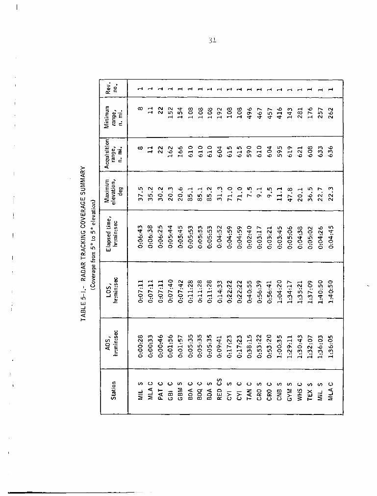
31
ix

APOLLO 6 (A-2 OR AS-502/CSM-020)
SPACECRAFT OPERATIONAL TRAJECTORY
VOLUME I - MISSION PROFILE
By W i l l i a m J . Bennett , and Ronny H. Moore, OMAB
and Jon C . Harpold, LMAB
1.0 INTROUDCTION AND SUMMAFY
1.1 Purpose
This spacecraf t opera t iona l t r a j e c t o r y def ined i n t h i s document i s designed f o r t h e unmanned Apollo 6 Mission (AS-502/CSM-O20/LTA-2R). This document presents t h e spacecraf t port ion of a combined launch vehic le and spacecraf t t r a j e c t o r y which i s designed t o s a t i s f y t h e spacecraf t mission objec t ives without v i o l a t i n g any of tht: lavnch vehic le and spacecraf t con- s t r a i n t s or t h e mission guide l ines . This r epor t descr ibes t h e complete mission p r o f i l e and incorporates a l l t r a j e c t o r y design refinements and rev is ions i ssued s ince publ ica t ion of t h e AS-502 Spacecraf t Reference Tra jec tory ( r e f . 1).
1 . 2 Scope
This r epor t i s presented i n four volumes. This volume, Volume I , summarizes t h e launch vehic le an2 spacecraf t da t a used i n developing a mission p r o f i l e which achieves t h e mission requirements spec i f i ed i n reference 2. It contains t h e mission gu ide l ines , input da t a f o r mission s imulat ion, and t r a j e c t o r y ana lys i s where appl icable . Also included are graphica l a d t a b u l a r t i m e h i s2or ies o f t h e spacecraf t a t t i t u d e , p o s i t i o n , dynamics, en t ry hea t ing , separat ion c h a r a c t e r i s t i c s , and a summary of t h e Manned Space F l ight Network coverage.
Only b r i e f descr ip t ions of t he launch, ea r th parking o r b i t s , and t r a n s l u n a r i n j e c t i o n phases of t h e mission are included i n t h i s document; more d e t a i l e d descr ip t ions are contained i n t h e AS-502 Launch Vehicle Operational Tra jec tory ( r e f . 3 ) .

2
Volume I1 of t h i s repor t contains t h e spacecraf t t r a j e c t o r y l i s t i n g of t he mission simulation and t h e spacecraf t input da t a spec i f i ca t ions . Also included a re de f in i t i ons of symbols and reference coordinate systems.
Volume I11 presents d e t a i l e d t r ack ing time h i s t o r y da t a of range, azimuth, e levat ion , range r a t e , and t h e two spacecraf t - to-radar look angles f o r t h e ground s t a t i o n s ava i l ab le during t h i s mission.
Volume I V presents an ana lys i s of t h e consumables useage f o r t h e Apollo 6 Mission.
1.3 Summax-y of Spacecraft Operational Tra jec tory
The purpose of t he Apollo 6 Mission i s t o demonstrate t h e s t r u c t u r a l compat ibi l i ty of t h e launch vehic le and spacecraf t and t o v e r i f y t h e adequacy of the Block I1 heat s h i e l d when subjected t o lunar-return en t ry condi t ions. and d i f f e r s from t h e Apollo 4 Mission pr imari ly because t h e second S-IVB burn i s a t y p i c a l t r ans luna r i n j e c t i o n burn.
This f l i g h t w i l l be t h e second launch of a Saturn V vehic le
For mission s imulat ion purposes, t he launch i s assumed t o occur at 13:OO Greenwich mean time ( G . m . t . 1 March 20, 1968 from pad A of complex 39 i n t h e Merr i t t I s l and Launch Area and on a f l i g h t azimuth of 72' from t r u e North.
The major events of t h e t r a j e c t o r y p r o f i l e a r e i l l u s t r a t e d i n f igu re 1-1. following phases.
For discussion pumoses t h e Drof i le has been divided i n t o t h e
1.
2.
3.
4.
5.
6.
7.
a. 9.
Saturn V ascent t o o r b i t .
Earth parking o r b i t .
Second S-IVB burn.
S-IVBJCSM separa t ion .
F i r s t SPS burn.
E a r t h i n t e r s e c t i n g coast .
Second SPS burn.
Preentry sequence.
Atmospheric en t ry .

3
I .
J
The Saturn V boost t o ea r th parking o r b i t cons i s t s of nominal burns of t h e S-IC and S-I1 s tages and a p a r t i a l burn of t h e S-IVB s tage . Thrust terminat ion occurs i n a near 100-n. m i . c i r c u l a r parking o r b i t . The vehic le remains i n t h i s o r b i t f o r approximately two revolut ions while vehic le sub- system checkout i s accomplished. No major propuls ion systems a re used during t h e two revolut ions i n e a r t h parking o r b i t bu t t h e o r b i t i s cont in- u a l l y per turbed by low-level t h rus t ing due t o LH vent ing and t h e ul lage-
engine burns t h a t occur during the i n i t i a l and f i n a l seconds of t h e park- ing o r b i t . Boost from parking o r b i t occurs during the second revolu t ion s h o r t l y a f t e r s i g n a l acqu i s i t i on by the Cape Kennedy t r ack ing s t a t i o n . The second S-IVB burn is an optimum burn which i n j e c t s t h e vehicle onto a conic t y p i c a l of t he t r ans luna r conics used f o r lunar landing missions. However, t h e launch vehic le i s not ta rge ted t o a t t a i n te rmina l condi t ions near t h e moon.
2
Af te r second S-IVB c u t o f f , t h e S-IVB o r i e n t s t h e spacecraf t t o t h e S-IVB/CSM separa t ion a t t i t u d e . a f t e r t h e start of S-IVB time base 7 and i s followed immediately by t h e CSM/S-IVB separa t ion sequence. The sequence c o n s i s t s of 10 seconds of CSM RCS +X t r a n s l a t i o n and a coast for 90 seconds t o obta in the a t t i t u d e and adequate separa t ion d is tance f o r t he f irst SPS i g n i t i o n .
This o r i en ta t ion i s completed 180 seconds
F i r s t SPS i g n i t i o n occurs 280 seconds a f t e r t h e s t a r t of S-IVB time base 7. A t completion of t h e f i r s t SPS burn, which i s nominally performed i n a retrograde a t t i t u d e , t he spacecraf t i s i n an o r b i t charac te r ized by an apogee a l t i t u d e of 11 989 n. m i . and an i n e r t i a l f l igh t -pa th angle at en t ry of -6". SPS fails t o r e i g n i t e f o r t h e second burn.
This ea r th in t e r sec t ing o r b i t insures CM recovery i f t h e
Approximately 6 hours a f t e r t h e f irst SPS burn i s completed and follow- ing a G&N pos i t i on and ve loc i ty update from t h e Carnarvon ground s t a t i o n , t h e SPS i s r e ign i t ed . This burn acce lera tes t h e spacecraf t so t h a t an i n e r t i a l ve loc i ty of 36 500 fp and an i n e r t i a l f l igh t -pa th angle of - 6 . 5 O are achieved a t en t ry i n t e r f a c e (400 000 ft). provided by t h e Guam t racking s t a t i o n . A t SPS c u t o f f , approximately 4 minutes of coast remain before the spacecraf t reaches en t ry . t h i s time t h e CSM o r i e n t s t o the desired CM/SM separa t ion a t t i t u d e , separa- t i o n occurs , and t h e CM o r i e n t s t o the required a t t i t u d e .
Coverage of t h i s burn i s
During
Atmospheric en t ry occurs at approximately 9 hours 29.5 minutes a f t e r l i f t - o f f at 154.96O E longi tude and 31.87O N l a t i t u d e . en t ry condi t ions , a m a x i m u m hea t ing rate of .372 ( B . t . u . / f t 2 ) / s e c and a t o t a l hea t load of 37 615 B . t . u . / f t 2 a re achieved. The m a x i m u m load f a c t o r encountered during reent ry is 5.74 g. shoot en t ry t r a j e c t o r y over a 2500-n. m i . range t o a CM sp lash poin t t a r g e t of 157.138' W longi tude and 27.354' N geodet ic l a t i t u d e .
A s a r e s u l t of t h e
The spacecraf t f l i e s a nominal under-

4
2.0 SUMMARY OF INPUT DATA
The input da t a summarized i n t h i s s ec t ion have been compiled from references 3 through 8 and include t h e pe r t inen t MSFN s t a t i o n spec i f i ca t ions and a quan t i t a t ive descr ip t ion of t h e spacecraf t . f i c a t i o n s of t h e spacecraf t can be found i n Volume I1 of t h i s r epor t . These d a t a fom the basis f o r t h e spacecraf t opera t iona l t r a j e c t o r y f o r t h e Apollo 6 Mission.
The d e t a i l e d d a t a speci-
2 .1 Saturn V Launch Vehicle
The Saturn V launch veh ic l e , i l l u s t r a t e d i n f igu re 2-1, i s comprised of t h e S-IC, S-II., and S-IVB s t ages . It w i l l p l ace t h e CSM/S-IVB i n t o parking o rb i t . Vehicle Operational Tra jec tory ( r e f . 3 ) . The condi t ions at t r ans luna r i n j e c t i o n , taken from t h e launch vehic le t r a j e c t o r y l i s t i n g , were used as t h e i n i t i a l conditions for t h e spacecraf t t r a j e c t o r y p r o f i l e .
Data fo r t h i s vehic le were based on t h e AS-502 Launch
2.2 Spacecraf t ( CSM-020)
The da ta necessary t o descr ibe t h e spacecraf t were obtained from references 4 through 8 and are summarized i n Volume I1 of t h i s r epor t . Spacecraft reference dimensions are presented i n f i g u r e 2-2.
2 . 3 MSFN Tracking S ta t ions
The locat ions f o r MSFN t r ack ing s t a t i o n s used f o r t h i s s imulat ion of t h e Apollo 6 Mission were obtained from reference 7 and a r e summarized i n t a b l e 2-1. Locations o f t h e two Apollo t r ack ing sh ips ava i l ab le for sup- po r t of t h i s mission are a l s o included i n these t a b l e s . The i n s e r t i o n s h i p , t h e Redstone, has been loca ted east of Bermuda I s l a n d t o provide extended coverage following i n s e r t i o n i n t o ea r th parking o r b i t . The en t ry s h i p , t h e Watertown, has been loca ted i n t h e P a c i f i c Ocean, east of Guam t o pro- vide r ada r coverage during t h e b a l l i s t i c s k i p and f i n a l phases of t h e CM e n t r y t r a j e c t o r y .
2.4 Spacecraft and At t i tude Reference Coordinate Systems
The spacecraft a t t i t u d e i s measured by t h e p i t c h , yaw, and roll angles requi red t o ro t a t e from a reference coordinate system t o t h e cu r ren t space- c r a f t o r i en ta t ion . The re ference coordinate systems used i n t h e generat ing t h i s p r o f i l e a r e i l l u s t r a t e d i n f igu res 2-3 through 2-8.
5
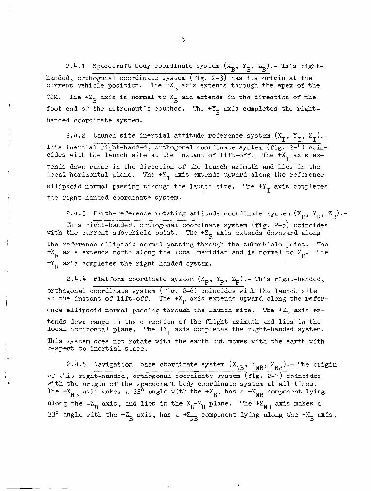
2.4.1 Spacecraft body coordinate system (XB, Y B , ZB).- This r igh t -
r
handed, orthogonal coordinate system ( f i g . 2-3) has i t s o r i g i n a t t h e current vehic le pos i t ion .
CSM. The +Z axis i s normal t o X and extends i n t h e d i r e c t i o n of t h e
foot end of t he a s t ronau t ' s couches.
handed coordinate system.
The +XB ax is extends through t h e apex of t he
B B The +YB axis completes t h e r igh t -
2.4.2 Launch s i t e i n e r t i a l a t t i t u d e re ference system ( X I¶ YI' zl).- This i n e r t i a l right-handed, orthogonal coordinate system ( f i g . 2-4) coin- c ides with the launch s i t e a t the in s t an t of l i f t - o f f . The +X axis ex-
tends down range i n t h e d i r ec t ion of the launch azimuth and l i e s i n the l o c a l ho r i zon ta l plane. The +Z axis extends upward along t h e reference
e l l i p s o i d normal passing through t h e launch s i t e . The +Y ax i s completes
t h e right-handed coordinate system.
I
I I
2.4.3
This right-handed, orthogonal coordinate system ( f i g . 2-5) coincides
The The
Earth-reference r o t a t i n g a t t i t u d e coordinate system ( X R , YR, ZR) .-
with t h e current subvehicle poin t . The +Z axis extends downward along
t h e reference e l l i p s o i d normal passing through t h e subvehicle poin t . +XR ax is extends nor th along t h e l o c a l meridian and i s normal t o Z R ' +YR axis completes t h e right-handed system.
R
2.4.4 Platform coordinate system ( X p , Yp, Z p ) .- This right-handed,
orthogonal coordinate system ( f i g . 2-6) coincides with t h e launch s i t e a t t h e i n s t a n t of l i f t - o f f .
ence e l l i p s o i d normal passing through the launch s i t e . The +Z axis ex-
tends down range i n t h e d i r e c t i o n of the f l i g h t azimuth and l i e s i n t h e l o c a l ho r i zon ta l plane. The +Yp axis completes t h e right-handed system.
This system does not r o t a t e with the ear th but moves with t h e e a r t h with respec t t o i n e r t i a l space.
The ++ axis extends upward along t h e r e fe r -
P
2.4.5 Navigation. base &ordinate system (XNB, yNB, z NB .- The o r i g i n
of t h i s right-handed, orthogonal coordinate system ( f i g . 2-7) coincides with t h e o r ig in of t h e spacecraf t body coordinate system at a l l t imes. The +%B axis makes a 33' angle with the +%, has a +XNB component l y ing
along t h e -2 axis , and l i e s i n t h e $-ZB plane. The +ZNB axis makes a B 33' angle with t h e +ZB a x i s , has a +Z component l y ing along t h e +X axis, NB B

6
and l i e s i n t h e XB-ZB plane.
coordinate system and coincides with t h e +Y
The +YNB ax i s completes t h e right-handed
a x i s . B Relat ive vehicle coordinate system (XRv, YRv, z RV ) .- This l e f t - 2.4.6
handed, orthogonal coordinate system ( f i g . 2-8) i s centered a t t h e cur ren t vehic le pos i t ion .
with t h e +% a x i s .
normal t o X
axis completes t h e left-handed coordinate system.
The +XRv axis extends i n t h e d i r e c t i o n of and i s co l inea r
The YRv ax is l i e s i n t h e l o c a l ho r i zon ta l p lane , i s
and is pos i t i ve i n t h e d i r e c t i o n of yaw r i g h t . The +ZRv RV '
2.4.7 Spacecraf t look angles (0 , 8 ) .- The spacecraf t o r i en ta t ion with respect t o t h e sun or t o t h e radar vec tor i s i l l u s t r a t e d i n f igu re 2-9 and is defined by the following two angles.
1. Theta The angle between t h e spacecraf t roll axis (+XB a x i s )
and t h e spacecraft-to-sun or spacecraft-to-radar vector .
2. Phi The angle between t h e spscecraf t negat ive yaw axis (-ZB a x i s ) and t h e spacecraft-to-sun (or r ada r )
vec tor pro jec ted on t h e roll plane ( Y -Z p l a n e ) .
From t h e r e a r of t h e spacec ra f t , t h i s angle i s measured pos i t i ve clockwise from t h e negative yaw axis.
B B
2.5 Orb i t a l Geometry and Trajectory Parameter Def in i t ions
The parameters which descr ibe t h e geometry of t h e o r b i t a l plane i n i n e r t i a l space and t h e vehic le s t a t e i n t h e o r b i t a r e presented i n t h i s s ec t ion . The parameters a re i l l u s t r a t e d i n f igu re 2-10 and 2-11 and a r e discussed i n t h e following paragraphs.
2 .5 .1 Orb i t a l geometry.- The s i z e of t h e o r b i t can be described by e i t h e r t h e semimajor axis o r t h e semilatus rectum of t h e e l l i p s e . shape of the e l l i p s e i s charac te r ized by t h e o r b i t a l e c c e n t r i c i t y . The semilatus rectum and t h e o r b i t a l e c c e n t r i c i t y a r e used as t h e t a r g e t i n g c r i t e r i a i n the guidance equations f o r t h e SPS burns. The semilatus rectum i s denoted i n f i gu re 2-10 as t h e d is tance from t h e cen te r of t h e e a r t h ( focus) t o the e l l i p s e measured a t r i g h t angles t o t h e major ax i s .
The
1

7
The o r i en ta t ion of t h e t r a j e c t o r y plane i n i n e r t i a l space can be descr ibed by t h e following o r b i t a l parameters.
1. Longitude of t h e ascending node - The angle between t h e ve rna l equinox and t h e ascending node of the e l l i p s e measured i n t h e plane of t h e equator .
2 . Orb i t a l i n c l i n a t i o n - The angle betwee.n t h e t r a j e c t o r y plane and t h e e q u i t o r i a l plane. of t h e ea r th .
The pos i t i on of t h e spacecraf t i n o r b i t can be descr ibed by t h e two
1. Argument of per igee - The angle measured i n t h e t r a j e c t o r y plane
following parameters.
from t h e ascending node t o t h e perigee poin t of t h e e l l i p s e .
2. True anomaly - The angle between t h e per igee poin t and t h e cur ren t pos i t i on of t h e spacecraf t on t h e e l l i p s e .
2.5.2 Trajectory parameters.- The vehic le s t a t e i n o r b i t i s usua l ly described by specif'ying a rad ius vector , l a t i t u d e , longi tude , a ve loc i ty vec to r , t h e f l igh t -pa th angle , and the azimuth which a r e referenced t o a given coordinate system. These parameters a r e i l l u s t r a t e d i n f igu re 2-11.

8
3.0 NOMINAL MISSION DESCRIPTION
A descr ip t ion of t h e Apollo 6 Mission s imulat ion and t h e r e s u l t s of pe r t inen t t r a j e c t o r y ana lys i s are presented i n t h i s s ec t ion . The ascent- t o - o r b i t , t he ea r th parking o r b i t , and t h e second S-IVB burn phases of t h i s mission s imulat ion are based upon t h e MSFC l i s t i n g of t h e AS-502 Launch Vehicle Operational Tra jec tory ( r e f . 3 ) . t h e cross-product s t e e r i n g guidance philosophy of reference 9 for t h r u s t vec tor cont ro l , and t h e reent ry phase uses t h e entry guidance log ic a l s o from reference 9.
The SPS burn phases u t i l i z e
The ear th ground t r a c k and t h e a l t i tude- longi tude h i s t o r y for t h e nominal mission p r o f i l e are presented i n f igu res 3-1 and 3-2, r e spec t ive ly . Earth shadow da ta (dayl ight and darkness) a r e a l s o i l l u s t r a t e d i n f i g u r e 3-1. A d i s c r e t e events summary i s presented i n t a b l e 3-1. The spacecraf t a t t i - tude summary i s presented i n t a b l e 3-11 and t h e SM RCS propel lan t expendi- t u r e s are summarized i n t a b l e 3-111.
3 .1 Prelaunch
For t h i s mission s imula t ion , launch i s planned t o occur March 20, 1968. The l i g h t i n g requirements a t t h e launch s i t e l i m i t t h e l i f t - o f f t o occur no e a r l i e r than 11:46 G . m . t . (6:46 e . s . t .1 . o f dayl ight should remain a f te r landing i n t h e primary recovery area, t h e launch can occur no l a t e r than 17:24 G . m . t . (12:24 e .s . t .1 .
S imi l a r ly , s ince 1 . 5 hours
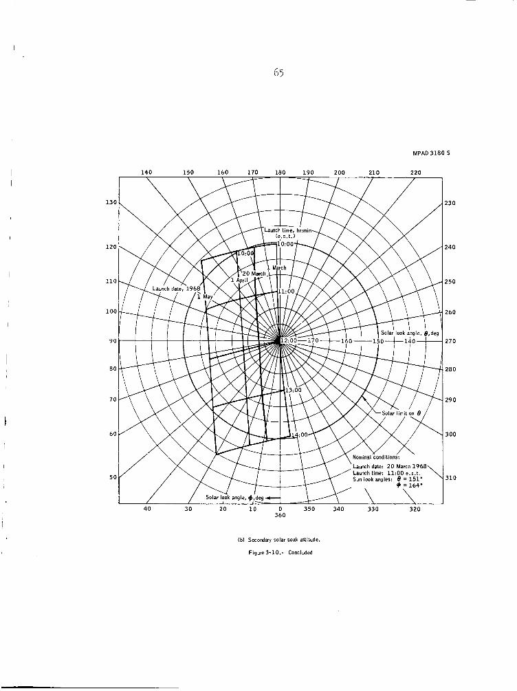
Another f a c t o r which r e s t r i c t s t h e launch window i s t h e s o l a r require- ment for heat-shield co ld soak. The requirement, as present ly defined l i m i t s l i f t - o f f t o occur no ear l ie r than 13:20 G . m . t . (8:20 e . s . t . 1 and no la te r than 18:54 G . m . t . (13:54 e . s . t . ) f o r t h e assumed launch da te . These cons t ra in ts and t h e r e s u l t i n g s o l a r a t t i t u d e o r i en ta t ion are discussed i n more d e t a i l i n s ec t ion 3.7 of t h i s r epor t . The e f f e c t s of sun l i g h t i n g and s o l a r requirements f o r hea t -sh ie ld co ld soak on t h e launch t i m e are i l l u s t r a t e d i n f i g u r e 3 - 3 .
3.2 Saturn V Ascent t o Orbi t
Launch of Apollo 6 Mission i s planned t o occur f i o ~ pad A o f launch complex 39 of t h e Merritt I s land launch area. of t h e launch s i t e a r e 28O36'30.32'' N l a t i t u d e and 80O36'14.88" W longi- tude . For the t r a j e c t o r y s imula t ion , launch w a s assumed t o occur a t 1 3 : O O G . m . t . (08:oo e . s . t . 1 on March 20, 1968. It should be noted t h e a c t u a l l i f t -o f f t ime w i l l be cons i s t en t with s o l a r o r i e n t a t i o n requirements given i n reference 10.
The geodet ic coordinates

9
3
The launch p r o f i l e of t h i s mission u t i l i z e s a 72O f l i g h t azimuth from t r u e north and includes the t h r u s t i n g phases of t h e S-IC, S-11, and S-IVB s tages . A summary of t he t r a j e c t o r y events during t h e phase i s included i n t a b l e 3-1.
MSF" coverage of t h e ascent-to-orbit phase is provided by t h e Cape Kennedy, Grand Bahama, Bermuda, and in se r t ion sh ip t r ack ing s t a t i o n s . The t r ack ing da ta for t h i s phase and the two revolut ions i n t h e ea r th parking o r b i t a r e consis tent with reference 3.
Time h i s t o r i e s of the t r a j e c t o r y c h a r a c t e r i s t i c s during t h e ascent- to -orb i t phase a r e presented i n f igure 3-4.
3.3 Earth Parking Orbit
A t f i r s t S-IVB engine cu to f f , which occurs 10 minutes 52 seconds a f t e r l i f t - o f f , t h e spacecrar t i s in se r t ed i n t o a 100-n. m i . c i r c u l a r parking o r b i t having an inc l ina t ion of 32.761' and a per iod of approximately 88 minutes. The s t a t e vector a t i n se r t ion can be descr ibed as follows:
Al t i tude , f't . . . . . . . . . . . . . . . . . . . 628 270.000 Geodetic l a t i t u d e , deg N . . . . . . . . . . . . . 32.639 Longitude, deg W . . . . . . . . . . . . . . . . . 55.088 I n e r t i a l ve loc i ty , f p s . . . . . . . . . . . . . . 25 569.913 I n e r t i a l f l ight-path angle . deg. . . . . . . . . . ' +0.001 I n e r t i a l azimuth, deg. . . . . . . . . . . . . . . 87.407
The vehicle remains i I i e a r th parking o r b i t f o r approximately two revolut ions while subsystems checkout i s made. The nominal S-IVB/CSM a t t i t u d e maneuvers during t h i s per iod a r e presented i n t a b l e 3-IV(a). major t h r u s t i n g occurs during the parking o r b i t ; however, t h e o r b i t i s continuously perturbed by low-level t h rus t ing due t o LH venting. Also,
t h e u l l age engine burns during t h e i n i t i a l and f i n a l seconds of t h e parking o r b i t per turb t h e o r b i t .
No
2
A t approximately 1 hour 34 minutes a f t e r l i f t - o f f , t h e S-IVB o r i en t s t h e spacecraf t t o an a t t i t u d e such t h a t t h e -Z axis of t h e spacecraf t w i l l be along t h e l o c a l v e r t i c a l . The S-IVB holds t h i s a t t i t u d e u n t i l approxi- mately 3 hours 8 minutes i n t o t h e mission when t h e S-IVB begins o r i en ta t ion for t h e second S-IVB i g n i t i o n . t h e hatch window w i l l photograph the ea r th .
During t h i s per iod , t h e camera mounted i n
The S-IVB p re ign i t ion sequence i s i n i t i a t e d a f t e r t h e spacecraf't passes over t he western coast of the United S t a t e s on t h e second parking o r b i t revolu t ion . During t h i s sequence , t h e launch vehic le maneuvers a t an assumed 1-deg/sec r a t e t o a l i g n t o t h e predetermined a t t i t u d e f o r t he
I 10
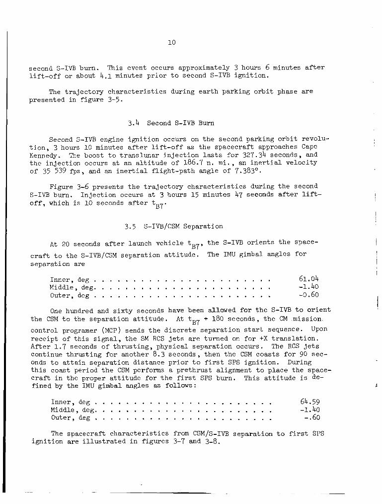
second S-IVB burn. l i f t - o f f or about 4 . 1 minutes p r i o r t o second S-IVB ign i t ion .
This event occurs approximately 3 hours 6 minutes a f t e r
The t r a j e c t o r y c h a r a c t e r i s t i c s during e a r t h parking o r b i t phase a r e presented i n f i gu re 3-5.
3.4 Second S-IVB Burn
Second S-IVB engine i g n i t i o n occurs on the second parking o r b i t revolu- t i o n , 3 hours 1 0 minutes a f t e r l i f t - o f f as t h e spacecraf t approaches Cape Kennedy. The boost t o t r ans luna r i n j e c t i o n lasts f o r 327.34 seconds, and t h e in j ec t ion occurs at an a l t i t u d e of 186.7 n . m i . , an i n e r t i a l ve loc i ty of 35 539 f'ps , and an i n e r t i a l f l igh t -pa th angle of 7.383O.
Figure 3-6 presents t h e t r a j e c t o r y c h a r a c t e r i s t i c s during t h e second S-IVB burn. o f f , which i s 10 seconds a f t e r tB7.
In jec t ion occurs a t 3 hours 1 5 minutes 47 seconds a f t e r lift-
3.5 S-IVB/CSM Separation
A t 20 seconds after launch vehic le t t h e S-IVB o r i e n t s t h e space-
The IMU gimbal angles f o r B7 y
c r a f t t o the S-IVB/CSM separa t ion a t t i t u d e . s epa ra t i on are
Inner , deg . . . . . . . . . . . . . . . . . . . . . . . 61.04 Middle, deg. . . . . . . . . . . . . . . . . . . . . . . -1.40 Outer, deg . . . . . . . . . . . . . . . . . . . . . . . -0.60
One hundred and s i x t y seconds have been allowed f o r t h e S-IVB t o o r i e n t t he CSM t o the separa t ion a t t i t u d e .
cont ro l programer (MCP) sends t h e d i s c r e t e separa t ion start sequence. Upon r ece ip t of t h i s s i g n a l , t h e SM RCS j e t s a r e turned on f o r +X t r a n s l a t i o n . Af'ter 1 . 7 seconds of t h r u s t i n g , phys ica l separa t ion occurs. The RCS je ts continue th rus t ing fo r another 8 .3 seconds , then t h e CSM coas ts f o r 90 sec- onds t o a t t a i n separa t ion d is tance p r i o r t o f irst SPS i g n i t i o n . t h i s coast period t h e CSM performs a p re th rus t alignment t o p lace t h e space- c r a f t i n t he proper a t t i t u d e f o r t h e f i r s t SPS burn. f ined by the IMU gimbal angles as follows:
A t tB7 + 180 seconds, t h e CM mission
During
This a t t i t u d e is de-
Inner , deg . . . . . . . . . . . . . . . . . . . . . . . 64.59
Outer, deg . . . . . . . . . . . . . . . . . . . . . . . -.60 Middle, deg. . . . . . . . . . . . . . . . . . . . . . . -1.40
The spacecraf t c h a r a c t e r i s t i c s from CSM/S-IVB separa t ion t o f i r s t SPS i g n i t i o n a re i l l u s t r a t e d i n f igures 3-7 and 3-8.

11
3.6 F i r s t SPS Burn
B7 ' The first SPS i g n i t i o n occurs 280 seconds a f t e r launch vehic le t
which corresponds t o 3 hours 20 minutes 16.94 seconds a f t e r l i f t - o f f . spacecraf t p i t c h a t t i t u d e at i g n i t i o n i s approximately 173.1' from t h e i n e r t i a l ve loc i ty vec tor or 25.8' below t h e l o c a l ho r i zon ta l . The burn lasts f o r 254 seconds during which the a t t i t u d e changes with respec t t o t h e ve loc i ty vector by only 6.4'.
The
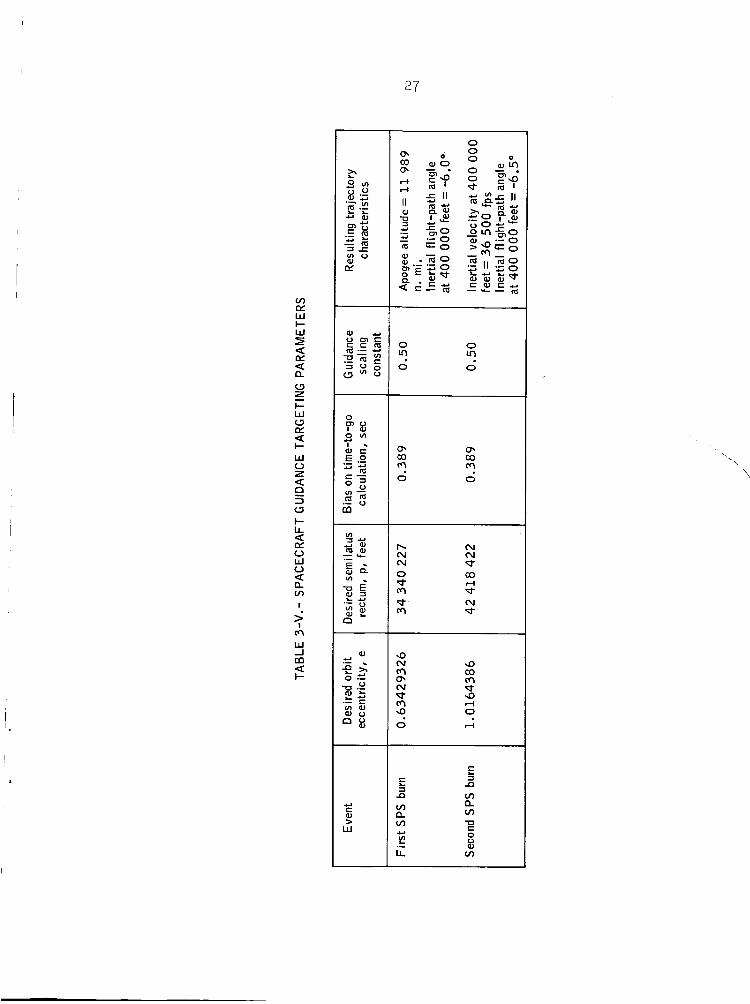
This burn i s t a r g e t e d using t h e cross-product s t e e r i n g log ic of reference 9 t o a coplanar e l l i p s e having a semilatus rectum of 34 340 227 ft and an e c c e n t r i c i t y of 0.63429326. 11 989 n . m i . and a per igee a l t i t u d e o f 18 n. m i . t i o n does not occur, t h e i n e r t i a l ve loc i ty and f l igh t -pa th angle a t reent ry w i l l be 32 813.4 f p s and -6O, respec t ive ly .
This e l l i p s e has an apogee a l t i t u d e of I f t h e second SPS igni-
I
Figures 3-l l(a) through 3-ll(e) present t h e spacecraf t t r a j e c t o r y c h a r a c t e r i s t i c s during t h e f i r s t SPS burn. Figure 3-11( f ) p resents t h e t i m e of f r e e f a l l (t f f Also presented on t h i s f i gu re a r e the instantaneous predic ted values of t h e i n e r t i a l ve loc i ty and f l igh t -pa th angle a t en t ry . s en t s a time h i s t o r y of t h e instantaneous apogee and per igee a l t i t u d e s during t h e f i r s t SPS burn.
t o t h e en t ry i n t e r f a c e as a funct ion of burn t ime.
Figure 3-ll(g) pre-
3.7 Earth In t e r sec t ing Coast
A t first SPS engine cu to f f , 3 hours 24 minutes 32 seconds a f t e r lift- o f f , t h e SPS in j ec t ed t h e spacecraf t i n t o an o r b i t charac te r ized by a semimajor ax is of 34 339 859 ft, an eccen t r i c i ty of 0.6342907, and an in 'c l inat ion of 32.49O. achieve t h e exact t a r g e t e l l i p s e o f t h e f i r s t SPS burn. However, t h i s i s wi th in the to le rances of t h e guidance cu tof f l og ic . The s t a t e vec tor a t i n j e c t i o n i n t o the coast e l l i p s e can be described as follows:
It should be noted t h a t t h e spacecraf t does not
A l t i t ude , f't . . . . . . . . . . . . . . . . . . . . . 6 229 926 Geodetic l a t i t u d e , deg N 9.253 Longitude, deg W 24.214 I n e r t i a l ve loc i ty , f p s . . . . . . . . . . . . . . . . 28 139 I n e r t i a l f l igh t -pa th angle , deg. . . . . . . . . . . . 24.504
121.299 I n e r t i a l azimuth, deg. . . . . . . . . . . . . . . . .
. . . . . . . . . . . . . . . . . . . . . . . . . . . . . . . . . .
Immediately following SPS engine cu to f f , t h e CSM i n i t i a t e s an a t t i - tude r eo r i en ta t ion maneuver t o place t h e spacecraf t i n t o t h e des i red a t t i - tude for cold soak. The proposed a t t i t u d e f o r co ld soaking CSM-020 i s def ined i n f igure 3-9. To achieve t h i s a t t i t u d e t h e spacecraf t -X axis i s

12
or ien ted toward t h e sun plac ing t h e CM i n shadow. Although t h e aforemen- t i oned a t t i tude i s optimum, t h e acceptable opera t iona l l i m i t s have been def ined so t h a t t h e sun-to-spacecraft vec tor may vary from t h e -X axis wi th in a 30' half-angle cone about t h a t axis.
These cons t r a in t s are def ined i n terms o f sun look angles , ph i and
Phi i s the angle between t h e spacecraf t -Z ax i s and t h e t a . Theta i s measured from t h e +X a x i s of t h e spacecraf t t o t h e sun- to-spacecraft vector . t h e pro jec t ion of t h e sun-to-spacecraft vector onto t h e Y-Z p lane , meas- ured pos i t ive clockwise. Therefore, consider ing only tht? s o l a r require- ment, an acceptable a t t i t u d e f o r CSM-020 would be one f o r which t h e t h e t a angle varies between 150' t o 180' and t h e phi angle va r i e s from Oo t o 360'. The phi angle i s var ied i n order t o obta in s a t i s f a c t o r y communications throughout t he cold soak. However, t h i s must be performed with due consid- e r a t i o n o f t h e gimbal lock l i m i t o f t h e I M U which i s 60" for t h e middle gimbal angle.
The primary a t t i t u d e def ined wi th in t h e above c o n s t r a i n t s i s given i n terms of IMU gimbal angles ( r e f . 11 and 12) as follows:
Inner , deg 111.83 Middle, deg. . . . . . . . . . . . . . . . . . . . . . . -28.16
. . . . . . . . . . . . . . . . . . . . . . . Outer, deg . . . . . . . . . . . . . . . . . . . . . . . 119.14
Figure 3-10(a) shows t h a t t h e primary a t t i t u d e i s wi th in t h e def ine4
A secondary a t t i t u d e which can be loaded i n t o t h e computer to le rances for t h e assumed launch between 8:20 and 11:45 e . s . t . on March 20, 1968. when a launch t i m e beyond 1O:OO becomes immivent i s wi th in t h e def ined to le rances from 1O:OO t o 02:OO e . s . t . as shown i n f igure 3-10(b) i s shown i n terms of IMU gimbal angles as fol lows:
Inner , deg . . . . . . . . . . . . . . . . . . . . . . . 139 * 79 Middle, deg. . . . . . . . . . . . . . . . . . . . . . . -41.46 Outer, deg . . . . . . . . . . . . . . . . . . . . . . . 173.75
A recent change t o t h e s o l a r requirements has requi red a reeva lua t ion of t he primary co ld soak a t t i t u d e . These changes and t h e i r e f f e c t on t h e primary cold soak gimbal angles w i l l be f i n a l i z e d s h o r t l y . The secondary a t t i t u d e w i l l remain unchanged. begins ca l cu la t ing t h e t t o e n t r y i n t e r f a c e .
The coast phase i s then set t o end 25 minutes before the f r e e - f l i g h t tra- j e c t o r y in t e r sec t s 400 000 f t .
Following SPS engine c u t o f f , t h e AGC
f f
Approximately 6 hours 22 minutes a f te r f i r s t SPS c u t o f f , t h e space- craf't reaches apogee a l t i t u d e and s tar ts i t s descent . A t t h e end of t h e coast phase, t h e spacecraf t pos i t i on and ve loc i ty and t
updated i n t h e AGC by t h e Carnarvon ground s t a t i o n i n prepara t ion f o r t h e
t o en t ry w i l l be f f

13
second SPS burn. Approximately 2 minutes ceived , t h e AGC i n i t i a t e s a r eo r i en ta t ion a t t i t u d e t o t h e i g n i t i o n a t t i t u d e f o r the
a f t e r t h e update has been re- maneuver from t h e co ld soak second CPS burn. The spacecraf t
holds t h i s a t t i t u d e u n t i l SPS i g n i t i o n occurs.
When t h e tff t o e n t r y fa l ls below 631 seconds ( tff min ) , t h e AGC
schedules t h e second SPS i g n i t i o n t o occur wi th in 2 minutes. The space- c r a f t coas ts i n an a t t i tude-hold mode u n t i l t h e t = 540 seconds. The
CSM RCS j e t s a r e then turned on f o r a 30-second u l l age maneuver. following t h e u l l age , t h e second SPS ign i t ion occurs.
f f Immediately
The spacecraft pos i t i on and ve loc i ty during t h e e s t h i n t e r s e c t i n g coast phase a r e presented i n f igu res 3-12(a) through (b) . t o r i e s of t h e IMU gimbal angles during t h i s phase are presented i n f i g u r e 3-12(e).
The time h i s -
3 .8 Second SPS Burn
The nominal mission p lan c a l l s fo r t h e second S-IVB burn t o acce le ra t e t h e spacecraf t s o t h a t a t en t ry t h e ve loc i ty i s 36 500 f p s and t h e f l i g h t - pa th angle i s -6.5'. spacecraf t t o coplanar o r b i t character ized by a semilatus rectum of 42 418 422 f t and an e c c e n t r i c i t y of 1.0164386. The cross-product s t e e r i n g l o g i c o f reference 9 i s again used for t h r u s t vec tor con t ro l . The dura t ion of t h i s burn is approximately 188 seconds.
These conditions are accomplished by t a r g e t i n g t h e
The spacecraf t p i t c h a t t i t u d e at SPS i g n i t i o n i s approximately 25' below t h e i n e r t i a l ve loc i ty vector o r 46' down from t h e l o c a l ho r i zon ta l . A t nominal SPS engine c u t o f f , t h e spacecraf t p i t c h a t t i t u d e i s 17' below t h e ve loc i ty vector .
Figure 3-13 presents t h e sp8cecraf t pos i t i on , a t t i t u d e , and dynamic c h a r a c t e r i s t i c s throughout t h e SPS burn. gimbal angle h i s t o r i e s . en t ry i n t e r f a c e .
Figure 3- l3(e) presents t h e I M U Figure 3-13(f) presents t h e t ime o f f r e e f a l l t o
3.9 Preentry Sequence
A t SPS second cutoff approximately 4 minutes remain before reent ry . During t h i s t i m e , t h e CM/SM separat ion and preent ry a t t i t u d e r e o r i e n t a t i o n maneuvers are performed.
ff When t = 200 seconds, t h e CSM i n i t i a t e s t h e r e o r i e n t a t i o n maneuver
t o t h e des i red a t t i t u d e f o r CM/SM separat ion (+X a x i s up i n t h e t r a j e c t o r y plane of motion 60' above t h e i n e r t i a l ve loc i ty v e c t o r ) . This a t t i t u d e is

1 4
he ld constant u n t i l tff = 85 seconds, at which time phys ica l CM/SM separa-
t i o n occurs. t h rus t e r s t o provide -X t r a n s l a t i o n . Trans la t ion continues u n t i l RCS pro- p e l l a n t is depleted.
The separa t ion maneuver i s performed by f i r i n g four SM-RCS
Approximately 5 seconds a f t e r CM/SM separa t ion t h e guidance and navi- ga t ion system w i l l begin r eo r i en t ing t h e CM t o t he predetermined a t t i t u d e f o r atmospheric en t ry . This a t t i t u d e i s .such t h a t t h e angle of a t t ack i s 1 5 7 O w i t h t h e lift vector up. f igure 3-15.
The preentry sequence i s i l l u s t r a t e d i n
3.10 Atmospheric Entry
Approximately 9 hours 29 minutes 23.59 seconds a f t e r l i f t - o f f , t h e CM en ters t h e atmosphere a t 31.867' N l a t i t u d e and 154.963O E longi tude. Reentry occurs at 400 000 ft; t h e i n e r t i a l ve loc i ty is 36 500 fps and t h e i n e r t i a l f l igh t -pa th angle i s 6.5' below t h e l o c a l ho r i zon ta l ( r e f . 1 4 ) .
Figure 3-16 shows a p l o t of t h e CM maneuver foo tp r in t and the nominal ground t rack on a map of t h e reent ry a rea . l oca t ion is 2500 n. m i . down range from t h e r een t ry i n t e r f a c e p o s i t i o n , and t h e ground coordinates of t h e t a r g e t a r e 157.179O W longi tude and ~ 7 . 3 2 6 ~ N geodetic l a t i t u d e . This t a r g e t l oca t ion w a s s e l ec t ed i n order t o maximize the t o t a l hea t load under t h e cons t r a in t s imposed by t h e re- en t ry guidance system parameters and operat ion. The increased hea t load r e su l t i ng from t h i s t a r g e t w i l l provide a more s t r i n g e n t t e s t f o r t h e hea t s h i e l d than t h a t obtained from Mission A-1, Apollo 4 .
The nominal touchdown t a r g e t
The nominal f l i g h t time from l i f t - o f f t o drogue deployment at 23 500-ft a l t i t u d e i s 9 hours 43 minutes 34 seconds. Figure 3-17, which shows a l t i - tude as a function of range from reent ry i n t e r f a c e , denotes t h e phase of t h e guidance system exercised. The load f a c t o r at t h e cen te r of g r a v i t y , which reaches a m a x i m u m of 5.74 g a t 9 hours 30 minutes 46 seconds a f t e r l i f t - o f f , i s shown as a function of time i n f i g u r e 3-18(a). h i s t o r i e s of t o t a l hea t load and t o t a l hea t ing r a t e are a l s o shown. The rad ian t heat ing r a t e s were ca lcu la ted from updated rad ian t hea t ing t a b l e s ( r e f . 13) which give about one h a l f t h e values t h a t t h e t a b l e s used f o r A-l/CSM 017 Mission would have given ( ref . 1). The maximum t o t a l hea t ing r a t e i s 372 (B . t . u . / f t * ) / s ec at 9 hours 30 minutes 30 seconds a f t e r lift- o f f , and the t o t a l hea t load i s .37 615 B . t . u . / f t 2 . Figure 3-18-(8) shows time h i s t o r i e s of a l t i t u d e , load f a c t o r , and bank angle commanded by t h e guidance system. While performing the guidance commands during t h e re - en t ry , t h e RCS system used 49.2 l b of f i e l . This f u e l consumption does not include any da ta before 400 000 f't, which i s approximat.ed a t 10 lb.
The t i m e

15
The time h i s t o r i e s of p o s i t i o n , i n e r t i a l and r e l a t i v e v e l o c i t i e s and f l igh t -pa th angles are presented i n f igures 3 - 1 8 ( ~ ) through ( e ) . Fig- ure 3-18(f) shows t h e a l t i t u d e , dynamic pressure, and Mach number as a funct ion of t i m e , and figure 3-18(g) gives t h e t i m e h i s t o r i e s of bank angle and t r i m angle of z t t ack . e f f i c i e n t s at t r i m angle of a t t a c k as a funct ion of Mach number. Fig- ure 3-18(h) presents a t i m e h i s t o r y o f t h e IMU gimbal angles during r een t ry .
Table 3-VI gives t h e Apollo 6 aerodynamic co-
I n f i g u r e 3-19, a l t i t u d e is p l o t t e d i n r e l a t i o n t o r e l a t i v e v e l o c i t y , and t h e boundaries f o r S-band and C-band communication blackout are shown. Al t i t udes below t h e boundaries are areas of communications blackout .
The drogue parachute deployment sequence s t a r t s at 9 hours 43 minutes 35 seconds af ter l i f t -of f at an a l t i t u d e of 23 500 ft. The two drogue parachutes are deployed 2 secon2.s l a t e r , A t an a l t i t u d e of 10 200 ft, 9 hours 44 minutes 24 seconds a f t e r l i f t - o f f , t h e low a l t i t u d e baroswitch c l o s e s , and t h e drogue parachutes are disconnected. The t h r e e main para- chutes axe deployed 1 second a f te r the baroswitch c loses . Table 3-VI1 presents t h e Apollo command module parachute descent events and aerodynamics. The CM, suspended on t h e main parachutes , reaches splashdown 9 hours 49 minutes 45 seconds a f te r l i f t - o f f .
t

16
4.0 MISSION PROFILES RESULTING FROM SPS ENGINE FAILURE
The second S-IVB burn of t h e Apollo 6 Mission is an optimum burn which i n j e c t s t h e vehic le onto a conic t y p i c a l of t h e t r ans luna - conics used f o r lunar landing missions. For t h e launch da te assumed i n t h i s r e p o r t , t h e vehic le w i l l not a t t a i n te rmina l condi t ions near t h e moon. However, if t h e SPS fa i ls t o i g n i t e fo r t h e f i r s t burn t h e spacecraf t i s committed t o t h e t r a j e c t o r y of t h e S-IVB. Assuming an 8:OO e . s . t . launch on March 20, 1968, t h i s t r a j e c t o r y is cha -ac t e r i zed by an spogee a l t i t u d e of approximately 275 920 n . m i . and a per igee a l t i t u d e of 1616 n. m i . However, if t h e SPS fa i l s during thl? secor,d SPS burn, t h e t r a j e c t o r y i s designed t o insure CM recovery. i g n i t i o n f a i l u r e i s presenked i n t h e following paragraphs and w i l l be d i s - cussed i n d e t a i l i n t h e a l t e r n a t e mission p lan .
A summary of t h e events for a second SPS
4 . 1 F i r s t SPS Burn; No Second SPS Burn
The f i r s t SPS burn i s t a rge ted t o a 11 989-n. m i . apogee coas t e l l i p s e which insures CM recovery i f second SPS i g n i t i o n does not occur. I n t h i s case t h e CM en te r s t h e atmosphere approximately 9 hours 31 minutes from l i f t - o f f with an i n e r t i a l ve loc i ty of 32 813.4 fps and an i n e r t i a l f l i g h t - path angle of -6.'. 159.07' E longitude.
Reentry occurs a t 32.28' N geodetic l a t i t u d e and
For t h i s ca se , t h e spacecraft w i l l f l y as far down range as poss ib l e i n an attempt t o achieve t h e nominal sp lash po in t . The maximum en t ry heat- i n g ra te achieved from t h i s p r o f i l e i s 202 (B . t . u . / f t 2 ) / s ec and t h e maximum load f a c t o r encountered during reentry is 5.18 g.
The CM splash f o r t h e no-second-SPS-burn t r a j e c t o r y occurs a t approxi- mately 9 hours 51 minutes a f t e r l i f t - o f f at 28.14' N geodet ic l a t i t u d e and 159.75' W longi tude. The landing f o o t p r i n t i s i l l u s t r a t e d i n f igu re 4-1.
4.2 Sui ia ry of Splash Points
The splash poin ts f o r t he spent SM s t age and t h e CM a r e Eummarized i n t a b L 4-1 and i l l u s t r a t e d i n f igu re 4-2. mission and no-secoiiri-SPS-burn en t ry and sp lash character!-stics i s presented i n tablf; . 4-11.
A comparison of t h e nominal

5.0 TRACKING AND COMMUNICATIONS DATA
The spacecraf t v i s i b i l i t y periods f o r t h e ground s t a t i o n s l i s t e d i n t a b l e 2-1 a r e presented i n t a b l e 5-1. The g romd t racking coverage during the ascent t o o r b i t , t h e second S-IVB burn , t h e SPS burns , and t h e preent ry sequence i s shown i n f igure 5-1. Spacecraft v i s i b i l i t y i s def ined f o r t r ack ing e leva t ion angles g rea t e r than 5. O .
Volume I11 presents de t a i l ed t racking time h i s t o r i e s o f range , azimuth , e leva t ion , range ra te , and two spacecraft-to-radar look angles fo r each of t h e ground s t a t i o n s and t racking ships ava i l ab le f o r operation on t h i s mission. These da t a include t h e ascent-to-orbit and t h e e a r t h parking o r b i t phases, as we l l as t h e ear th- intersect i r ig coast and r een t ry phases.
I
t

aJ
L
S 0 Y m u VI
.-
N b N W 0
N N r- d m
9 W N rl m
9 m m d 9 h
9 m 0 m m 6
d d N 6 0
b m W d N rl
d m 9 rl d m
9 0 N m 9
0 m b m m 9
W m m m m d
m m b rt W m
0 0 0 0 0 0

U W
3 2 - 0 V I
In w r- m a n a n a
-I -
0
z
al 0 .- 8
(v 9 a d N d
m m In 9 N N
0 In m 9 m 9
m 0 rl 03 d m
d 9 c3 I- d m
I-I rc\ 0 U U I-I
9 0 N m 9 I-
4 9 I- N r- m
N c3 0 N N rl
m 0 m N a In
N cu N a In m
I- m I- 0 0 0
m 0 d I- m a
0 0 0 0 0 0
0 0 0 0 0 0
C 4 a

20
2
3 U z v)
v) I- z w ?I W F W 0: u E n
P
E H Q 0 A A 0 a U
T m W -I
I-
z v)
I
m a
an 0 .- U
?I Q
> E U
v)
m n
v
L
aJ 73 3 0
e- U - -
I-
I I
0
Q 'I 0 -2 0 0
0 0 0 g 0 0
W
0
N
? 'I! z
0
43
W
? 'I! z
I- O N
0
0
'" T!
b 0 N
d
0
0 T!
0
m 0
==!
0 T! m
rr
Q
m m
'I 'I! r'
d
9
m m
0: 'I! r'
I
\
i
3

21
Y
S aJ W
N 9
m rl rl
d; P m
rl N r(
'u. co P
m 03
? rl m N. e a
9 b
2 9
rl I-
0 b
d;
r( m I- h
6; m v! m
N
c\I
m m
e co N.
co rl 0 0 m
P 0 0 0 m
m m m m m m m m m m m m m

22
0 0 0 0
b E 0 0
m m m m m b b m m m 0 9 0 9 'I b b r l r l m m m
?'I 'I '1'1'1 09 c o c o c o co
b b b b b b b rl r l r l rl r l r l r l
4 c o c o co
VI" 0 0 0 9 9
- N ( v VI V I V I VI
0 d d V I V I
9 d VI
0 9 b . b . 0 0 0
c 9 0 9 c9 0 0
. z z m 09 5 9 4 0 0 0 -
- S 0 .- Y
f Q W Y)
H v) 0 \ m z A
W W rn 0
8

I
u) m m c o c o b b ,b u) u)
0 0 0 0 0 rl A r c d- Y 0 0
r l r l . . rl 0 9 9 ' v . q I I 1 I
I rl
0 0 0 0 0 m m m rl rl
0
0 rl r l r l o o 4
v! v! 0 0 . . rl ! ! ? ? I I 7 7 0 1 1 1 1

24
TABLE 3-111.- SERVICE MODULE RCS PROPELLANT EXPENDITURES ~~
Maneuver
CSM/S-IVB separation (1 0 sec of +X translation)
Attitude orientation to f i rst SPS burn attitude
SPS cutoff damping
Attitude orientation to solar soak attitude
Attitude hold mode (0.2-degree deadband)
Attitude orientation to second SPS burn attitude
30-second RCS ullage prior to second SPS ignition
SPS cutoff damping
Attitude orientation for CM/SM separation
CM/SM separation
To tal
I C s propellant expenditure,
Ib
14.4
3.8
1 .0
8.9
128.3
8.9
43.2
1.0
8.9
a561.6
780.0
NOTE: Propellant expenditure data was used in this simulation for weight bookkeeping. Volume IV of the report should be consulted for the official breakdown of RCS propellant consumption.
a CM/SM separation burn ends with RCS propellant depletion.

25
TABLE 3-IV.-, SUMMARY OF S-IVB ATTITUDE MANEUVERS
(a) Earth parking orbits
Maneuver
Maintain commanded cutoff inertial attitude
Initiate maneuver to al ign S- IVB/CS M +X axis with local horizontal (CSM forward, +ZB up) and maintain orbital rate
Roll 180" down and maintain orbital rate
Initiate 20" pitch down maneuver and maintain orbital rate
Initiate 20" pitch up maneuver to the local horizontal and maintain orbital rate
Initiate 180" roil maneuver to place +ZB down. Maintain +X axis along local horizontal until the beginning of the restart sequence
i s orbital insertion cutoff command a 65
l i m e from lift-off, hr:mi msec
(a)
0:10:45.9 (tB5 + 0 sec)
0 : l l : O O . 9 (tgg + 15 sec)
0: 12:15.9 (tB5 + 90 sec)
0 5 ~ 4 5 . 9 (tB5 + 2460 sec)
1:28:45.9 (tB5 +4680 sec)
1:34:45.9 (tB5 +5040 sec)

26
TABLE 3-IV.- SUMMARY OF S-IVB ATTITUDE MANEUVERS - Concluded
(b) Post injection
~- ~
Maneuver mode Maneuver
Maintain second S-IVB commanded cutoff inertial attitude
Initiation time of maneuver from maneuver from lift-off, l i ft-off, hr:min:sec hr:min:sec
Terminal time of
Orient to CSM/S-IVB separation attitude at 1.44 deg/sec in each axis Separation attitude:
Inertial yaw = 0.849' Inertial pitch = 2 4 1 . 9 6 7 " Inertial roll = 178.732"
Maintain CSM/S-IVB separation attitude
Programmed
Programmed
~~
I U sends separation start sequence discrete to the CSM
3:18:38.64 (tg7 + 181.7 sec)
3:20:16.94
CSM/S-IVB separation
Programmed
Fi rs t SPS ignition (tg7 + 2 8 0 sec)
3:2 5:36.94 3:35:36.94 Orient to post-separation inertial attitude Post-separation attitude:
Inertial yaw = 0" Inertial pitch = -164" Inertial roll = 2"
Hold post-sepG,ation attitude
Orient to align S-IVB/IU/SLA +X axis with local horizontal SLA fotwad
Programmed 3:15:36.94 3:15:56.94
3 : 18:36.94 I 3:18:01.06 I Programmed
Programmed 3:15:36.94
I I I I
Programmed 3:3 5:36.94 5:15:36.94
Ground command 5:15:36.94
backup I I
- Launch vehicle time sequence tB7
I
v) E W I- W H d 2 a z I- W a E
I- W V z
-
a
5 3 a I- LL
0 W 0
d
2
?
v)
I
m W J
i-
m a
1.
0 0
0 0 In m 0 0
Q’ 03
0 1
OI W
0 1
r- (v N N N d- 0 W d- rl m d- d- N m d-
9 (v d3 - m co OI m (v d d 9 m rl 9 0 0 rl
E E a
a n
t? LL m
3
I) v)
v) v)
v)
3
U S 0 Y
8 .-
\
‘\
\

28
Y 0
I- I-
LL 0 w -I a z
a
a
a z
a
w u
w I- l-
v) I- z
LL LL w 0 0
u I I &
a 0 e W
9 0 -I J 0 11 a
=: m a
I. - m W J
I-
N W M I 3 z I 0
2 LI 0 z
I- V z 3 LI
v)
a
E!
a a
J 0
X + 0 n 'z
Y-
/ E .- L Y
\ \ \
- E .-
n3 \ J
E .- L
a4 0
\ \ \

I.
TABLE 3-Vl l . - APOLLO COMMAND MODULE PARACHUTE DESCENT EVENTS AND AERODY NAMlCS
Event
High altitude baroswitch closed (actuate ELS 1
Deploy drogue chutes a
Drogue line stretch
Drogue chute reefed inflation
Drogue chute disreef
Drogue chutes full open
Low altitude baroswitch closed
Deploy main chutes
Main line stretch
Main chute reefed inflation
Begin main chute disreef
Mains ful l open
b
a There are two drogue parachutes.
bThere are three main parachutes.
~~
A It i t ude , f t
23 500
10 200
0.0
2.0
2.7
2.8
10.8
11.0
0.0
1.0
2.0
3.5
10.0
13.0
COS per chute,
f t2
0.0
0.0
0.0
40.0
40.0
68.0
0.0
0.0
0.0
300.0
300.0
4000.0

30
TABLE 4-1.- SPLASH POINTS
Vehicle
Service module
Nominal
Command module
No second SPS burn
Nominal
Time of impact from lift-off, hr:m i n: sec
9:34:19.0
9:51:23.9 9:49:45.2
Impact Impact I at i tud e, I ong i t ud e,
32.6
28.14 27.35
166.2
-1 59.75 -157.14
TABLE 4-11 .- COMPARISON OF NOMINAL AND NO-SECOND-SPS-BURN ENTRY
Parameter
G.e.t. at entry, hr:min:sec
Geodetic latitude at entry, deg
Longitude at entry, deg
Inertial velocity at entry, fps
Inertial flight-path angle at entry, deg
Inertial azimuth at entry, deg
Maximum load factor, g1 nd 2 Maximum heat rate, Btu/ft /sec
Total heat load, Btu/ft
Geodetic latitude at splash, deg
Longitude at splash, deg
Time from entry to splash, hr:min:sec
Ground range from entry, n. mi.
2
~~
Nominal
9:29:23.6
31.867
154.963
36 499.9
-6.501
82.52
5.74
372.0
37 615.0
27.35
-157.14
00: 2 0: 25.6
2500
No second S PS burn
9 3 0:48.7
32.28
159.07
32 813.4 -6.01
84.89
5.18
202.0
26 537.0
28.14
-159.75
00:20:35.2
2295
I
2 6 H H 3 v)
W a lY W > 0 V a
a
5 V 6 lY !- cc 6 0
oi a
I. - I u) W -I
I-
m a
CI S 0
m 5 W W
m 0
m E
.- Y
- 0
Y
0
0,
2
2
Y-
W m
W 5 0
K 0
m v,
.- Y
Y

32
U aJ 3 8
S
.- Y
s 2 a
f
I
2
v, W U
W > 0 0 U
Y 0
I- fY
a
z s d a fY I
I - In W J m a I-
A 8 0
m 5 W aJ
In
.- Y
- 0
s 0 In E 0, L
aJ 5 > 0 t!
I
I

33
W I
d
b
0
d ?.
rl
d-
d
F1 %
0
d
0
'v 'v
l-l
a)
d
I %
rl
m
d-
0 'v
PI
a)
0
0 0
d
(v
0
9 0

34
\ Typical translunar el I ipse
1.
2. 3. 4. 5. 6. 7. 8. 9.
10. 11.
Apol I o
I I I I I I I I I
I \ 5-4
3 6
6 Sequence of Events
Insertion to a 100-nautical mile circular parking orbit for two revolutions. Injection onto a 72-hour lunar transfer el l ipse. SIVB/CSM separation and first SPS burn. First SPS cutoff and earth intersecting coast. 12 000-nautical mile apogee. Second SPS ignition. SPS engine cutoff. SM/CM separation. Atmosphere entry. No second SPS burn splash. Nominal splash.
100-n. mi. parking orbit
Figure 1-1.- Mission summary.

t LAU'NCH 350.737 ESCAPE
1 SYSTEM t26
1 36.00 476 .OS5
1
- 396 759 .Ooo
4140.792 I
1441 .m
STA 4240
3890.055 3749.555
3594.555
SPACECRAFT
IN STRUMEN T 3" 58' - STA 3258.555
STA 3222.555 -
s-IVB - STA 2746.500 - GIMBAL STA 2645.853 ' 16044' STA 251 9 .OOO
I s-it
- STA 1760.OGO - GIMBAL STA 1664.000
s- IC
- GIMBAL STA 1OO.OOO - STA 48.500
STA - 1 15.494 1 Flgure 2-1,- Saturn V reference dimensions,

36
, 37.062 4 . 0 0 RAD N O S E - L A U N C H ESCAPE SUBSYSTEM
SPACECRAFT LEM ADAPTER
1484.24
1141.25 (THEORETICAL
1133.5 ( C M N O S E )
1083.48
1016.75
8 3 3 . ? ( E N G I N E GIMBAL
100.5 DIAMETER
SLA STABILIZING MEMBER
Notes: @ Separation Plane
v Field Splice
AI I I inear dimensions are in inches.
C O N E APEX)
P I A N E )
Figure 2-2 .- Command and service modules reference dimensions,
37
m -I 0 - I x
" 1 , -I-
x
'.
38
.
f - X
I I-
E a m % m Q) U
U
.- n 0 0 0
U U (d
a U .L

39
+ )
Y
. E a, 4 cn v)
'. a,

40
a N
I I-
a X

41
I
m z >.
4
a >-
a X
/
rn a, 0
2 .- -E 0 0 0
4 b b
2 0 a, 0 m Q rn 0 4
rn
0
S 0 4 m .-

42
> Qf
N
W -I o I W > >. e a n z
-
n a x + c3 z 0
0 o W v)
n w z -I
-I
I- z 0 N e 0 I -I
o 0 -I z
a a
a
-
a
- v
> e >.
aJ U
!! -E .- 0 0 0 aJ 0 c 0) >
d .-
op cu
e a

43
W
w J
O F 0 -I
I.
Y 0 0 - e e 0 a, 0 m n
UJ
I.
T N

44
DESCENDING NODE
EQUATORIAL PLANE
V INERTIAL VELOCITY
P SEMILATUS RECTUM
T VERNAL EQUINOX
w ARGUMENT OF PERIGEE
INERTIAL LONGITUDE OF ASCENDING NODE
1
e TRUE ANOMALY
i INCLINATION
a SEMIMAJOR AXIS
R RADIUS VECTOR
c CENTER O F E L L I P S E
Figure 2-10.- Orbital geometry.

45
7 LOCAL HORIZONTAL PLANE
GREENWICH MER IDlAN V
h x 'G 4c 4 R
V
A N
r T S 0
RIGHT ASCENSION OF GREENWICH
RIGHT ASCENSION OF VEHICLE
VE HlCLE LONGITUDE
GEODETIC LATITUDE
GEOCENTRIC LATITUDE
VEHICLE DECLINATION
RADIUS VECTOR
INERTIAL VELOCITY
INERTIAL AZIMUTH
TRUE NORTH
INERTIAL FLIGHT-PATH ANGLE
VERNAL EQUINOX
SUBSATELLITE POINT
CENTEROF THE EARTH Figure 2-11.- Trajectory parameters.

0 0 N s VI
0
46 0 N 0 U 0 VI 0 m

IuEII Sequence of Events
1. First S-IVB ignit ion 2. First S-IVB cutoff 3. Second S-IVB ignit ion 4. Second S-IVB cutoff 5. S-IVBICSM separation 6. First SPS ignit ion 7. First SPS cutoff 8. Apogee 9. Second SPS ignit ion
10. Second SPS cutoff 11. CMISM separation 12. 4ooMxIft 13. CM splash
I
120 160 160 120 West Longitude, deg East West
(a) Mission profile. 120
100
.- . a E 6 w- 60
a
-0 = c c -
40
20
0 8 8 8 4 80 76 72 6 8 6 4 60 56 52 48 4 40
West longitude, deg
80
.- . 6 0 E c' w- 40
a
U 3 c c -
20
0 W 158 162 166 170 174 178 178 174 170 166 162 158 East Longitude, deg West
(c) Entry phase.
Figure 3-2.- Altitude-longit ude history.

48
Splash 1.5 hrs wior to sunset, Pacif ic recovery area h a n d atory 1
1400
1300
1200
11 00
I I 11 21
0500
t I I
I I 1 I 10 20 10 20 I
J 1000 /
- 0900
i m i t for primary solar attitude
0800
0700 ‘1 -
0600 -
Splash 3 hrs prior to sunset, Pacif ic recovery area (highly desirable)
Launch 0.5 hr after s unri s e

49
6ap ‘y ‘apnl!6uo1
2 a L 0
0 7 c
2 m CL
8
::
E
c c al
10 w
= m v)
I
c
p‘ M
E 3 Is)
U .-
0 h

51

52

53
8 d 0
W
cn c m
-
8 &i 0
8 s-4 0
p' m W L
3 (3
LL .-

54
O Z Z m

55
0
w 9 N W d +I
tu 9 w d r l r l I I + (
P Y d r l rl
Y 1 1 I I I I I I 1
I I 3 P 0 0 0 0 0 0 0 0 0 d m N rl rl N
6ap 'p+ 'apnyjel qlapoat) m 0 4
X I I I I I I I I 0 0 0 0 0
N rl 0 m 9 9 9 9
d 9
0 0 0 IC 9 tn 9 9 9
0 W 9

56
0
m 0
T!
0
m 0
c?.
0
N 0
T!
0
(v 0
0
0
d 0
T!
0
rl 0
0
0
0 0
T!
0 0 0
0 0 0 0 0 0 0 00 N rl 0 m a3 b 9 m rl rl rl
W 9 d N 0 (v d 9 9 9 O. 9 9
a3 b 9 m d. m m m m In In In N N N N N (v
rl 0 m m m m
N rJ N
'? L? L? L? L? L? L? 9 9
K .- E z
Y
c .- 5 c .- E e L
E .- Y
Y v)
m 0 U In Q m
W -
0
(u 0
0
0
d 0
41
rl
N
rl
0 0
- 0 r;!

57
0
d 0
F!
0
m 0
PI!
0
m 0
Fl
E .- 0
2 f E .- z
0 .z
o * c - d
a v)
0 0 0 P I ! = d $
0 % - W
0
d 0
F!
0
0 0
PI!
0 0
I I I I I
W d P ? b p ' h d Apoq le!VJul
0 0 0 0 0

I I I I I I I m cu rl 0 m 03 r- m m m m cu cu (u
0 0 0 0 0 0 0 0 0 0 0 0 0 0 ru rl 0 o* 03 r- 9
E e L
E .- e
w

59
0
g o 0 CO 9 P N 0 CO 9 rl 0 0 0 0 0 0. m d rl d d rl d
1 I I I I I I I I
m m 0
1
d
m 0
1
m m 0
T!
(v
m 0
T!
rl
1 m 0
7! m 0

60


62
0 0 0 0 0 0
d 9 d N
0 0 0 0 W 9 d N 0 CO d d rl d
0 d d
0 0 d
0 rn
0 CO
0 aJ o w bK-
e 0 .- Y
m n g g
rn 2 m
z 2 u
L k
E O ? ! d .-
I-
O r.3
0 cu
0 rl
0

63
v)
Q) h 0
D * c
4
M N I
v) W J c3 z z 3 v)
a
\ ' m X
I
\
c3 8 W a
m I= U 0 aJ ul
.-
c m Q)
e m c - 3' W
c 0 - L. 0
0 m U
it! p!
kz
0 aJ 0
v)
I. 0
w I
2 3 m .-
LL J 0 v)

64
MPAO 3179 s
30
40
50
'60
' 70
!80
!9 0
300
310
(a) Primarv solar soak attitude.
Figure 3-10.- Effect of launch delay on sun look angles.
65
130
120
110
100
9 0
80
7 0
60
50
MPAD 3180 S
!30
!40
!50
!60
!70
!EO
!9 0
300
310
(b) Secondary solar soak attitude.
Figure3-10.- Concluded

66
0
j n m m a
c Y
.- LL
I
rl rl I m 2 J m .-
LL
rl I I I 1 I I I ln d m N l-4
X co b 9
y '4 'aPnl!llv

67
m (v rl (v (v (v rl 4 rl
L% 0
9 m 0

68 0 0
d

t
m m 0
- Y
(v
m 0
- 9
rl
m 0
- 9
6. 0 1,1
L% 0
Y m 0
S I
E L s
Y
s
E
0 7
aJ .
Y
-0 aJ ul P m aJ -0 S 3
CI
-
2

03 :2 1 03:22 03 :23 03 :2 4
(e) IMU gimbal angles.
Figure 3-11.- Continued.

c9 Y 9 9 'v. 09 7 d d d m m N (v m m m m m m m
I
0
m 0
?!
0
m 0
I
m 90 (v m
? rl! 'v
0
-U
m 0
0
d
m 0
'v
'v
0
d
m 0
c! 'v
0
m m 0
T v
0
m m 0
'v 'v
h
8 aJ m aJ u7 S m z m 0 I z m
L Y
u
-
u
Y
.- - - -0 S m =l Y 0 0 aJ 5 -0 aJ 0 U
0.
-
Y .- 2 . L Y
S aJ
0 E Y - - m aJ - 2 L
L 0 aJ E
I- .- h L Y
73 aJ 3 S
C 0 0
.- 4
I. rl I+ I m E 3 0, .-
L L

0
9 0
0
0
In 0
0
0
rl 0
0
0 0
0 Q! 0 0 0 0 0 0 0
0 0 0 0 0 f- 9 In d- m (v rl m 0
0 0
0 0 0 0 0 0 0 d- (v 0 a3 9 d- (v 0

73


75
I I
I
1
~
I
i I
I
I 1
I

76

77

5200
4800
4400
4000
.c) 7 3600 r al -0 3 Y .- $ 3200
2800
2400
2000
160C
09:23 09:24 09:25
to3 28
27
26
25 m aJ U
4
- 2 2 4 5
al U s
m V
a -0 0 aJ 0
Y
Y .-
- - 23 .- Y
- 22
- 2 1
- 20
19 -
134
132
130
- 128
0 aJ
- 126 2 . aJ U 3 Y .-
- F 124 0 .-I
122 -
- 120
118 -
- 116 0o:oo 01:oo 02:oo 03:OO 04:OO
Elapsed time from second SPS ignition, min:sec
(a) Altitude, latitude, and longitude.
Figure 3-13.- Second SPS burn.

79
37
36
I 35
I 3 4 cn W U I . >-
L 33
3 1
I 30
29
28
l o 3 -15
-1 6
-1 7
. E -18 U . .- x . W -
- -19 m
m Q
I:
5
Y
. cn -20 .- G m - .- CI
2-J = -21
-2 2
-23
-2 4
- 72
71
- 70
69
rn W
. 68 4
3 4
5 E 2 - 67
66
65
64
63 0o:oo 01:oo 02:oo 03:OO 04:OO
Elapsed time from second SPS ignition, min:sec
I I 09:23 09:24
09:22:13.8 09:25:22.3 Ground elapsed time, g.e.t., hr:min
(b) Inertial velocity, flight-path angle, and azimuth.
Figure 3-13.- Continued.

80
-178.8
8: -179.2
e '- -179.6
-0
- - - m 2 S -
-180.0
-0
ul 4 -.4
j.,
2
h
m - .- -.8 8 -
-1.2
28.4
28.0
- 27.6
- 27.2
26.8 m W U
r 0
. - 's 26.4 - m .- % c -
26.0
25.6
25.2
24.8
24.4 0o:oo 01:oo 02:oo 03:OO 04:OO 05:OO
Elapsed time from second SPS ignition, min:sec
09:23 09:24 09:25 I 09 :25: 2 2.3
I 09:22:13.8
Ground elapsed time, g.e.t., hr:min
(c) Inertial yaw, pitch, and roll.
Figure 3-13.- Continued.

180
160
120
80
09:23 09:24 09:25
I -4 0
, -8 0
I
-120
-160
-18 0
0o:oo 01:oo 02:oo 03:OO 04:OO 05:OO Elapsed time f r o m second SPS ignition, min:sec
(d) Relative yaw, pitch, and roll.
Figure 3-13.- Continued.

82
Elapsed time from second SPS ignition, min:sec
0923 09:24 09:25 I 09:25:22.3
I 09:22:13.8
Ground elapsed time, g.e.t., hr:min
(e) IMU gimbal angles.
Figure 3-13.- Continued,

560
52 0
48 0
0
I Yz 440
2
8 400
a
0
0 0 d 0 Y
= 360 2 0
2
2 L
320 .- I-
280
240
200
-5.9
-6.0 cn V
F a -6.1 Y
0 m c -
5 -6.2 2 Y -c cn
u -6.3
e n
.- - L
Y
.- U
-6.4
-6.5
04:OO 05:OO Elapsed time from second SPS ignition, min:sec
I I I
09:23 09:24 09:25 09:22:13.8 09 :25: 22.3
Gmund elapsed time, g.e.t., hrmin
(f) Time of free fal l to reentry, predicted velocity and flight-path angle at entry.
Figure 3-13.- Continued.

84
900 x -
800 -
-
700 -
-
600 __
.- - E c
Q
U U
500 - 9 .- - - m
400 - 0 7 0
2 -
300 -
200
-
100 -
-
o = 0o:oo
22 I
21
20
.- E. c
aJ U =l
. 19
4.J
Y .- - m % 18
a
cn aJ .- L
I 17
I 16
15 01:oo 02:oo 03:OO 04:OO 05:OO
Elapsed time from second SPS ignition, rnin:sec
1
I 09:23 09:24 09 :2 5 I I
09:22:13 .a 09:25:22.3
Ground elapsed time, g.e.t., hr:min
(9) lnstaiitaneous apogee and perigee altitude.
Figure 3-13.- Concluded.

85
0 0 m 0
..
0 d- (v 0
..
0 (v
(v 0
..
o m ( V S .. .. 0 ‘E .
8 0 2
O E o = ( v *
A 3
d- ;;; v)
0 0 E
0 - o a ,
o i -
0,
2 .s
0 d- 0 0
..
0 (v
0 0
..
0 0 ..
0
m 0
ci!
m m 0
c?!
a3
m c?! 0
0
d In ..

86
0 c S
a l-4 0
0 8 ($ 0 0
m 0 c

87
O g L% In
‘u Q. 0
0 00 W N 0 00 W N
m m rn ui m m 2 m ui ui
m m d m d m 2 m h’ d d

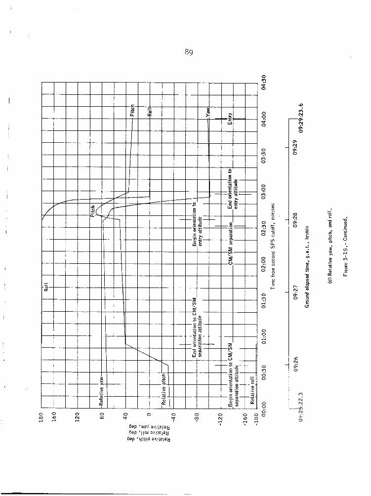
89

0 'I! 0
0
* 0
Fi
0
" 0
m
0
n 0
0
V
'?.
E 0 .
N r
v,
v, U
.-
5 % 0 :
a
0 2 0 : Z E
0,
E I-
L
aJ ._
O
PI 0
CI!
0
4 0
0
0
0 0
'I!
0 0

91
l30 140 1% 160 170 180 170 160 1% 140 130 120 110 100 90
80 80
70 70
60 60
50 50 Altitude = 400 000 f t
40 40
30 30
g 2 0 20
d r 10 10 II
0
i l: 10
20 20
30 30
40 40
50 50
60 60
70 ~~~
70130 140 1% 160 170 180 170 160 150 140 130 120 110 100 90 Longitude, deg
Figure 3-16.- Spacecraft landing footprint.

92
0 0 0 0 0 0 0 In 0 Ln 0 LA 0 Ln m m N N rl ?I
l j ’Y ‘apnl!l lv
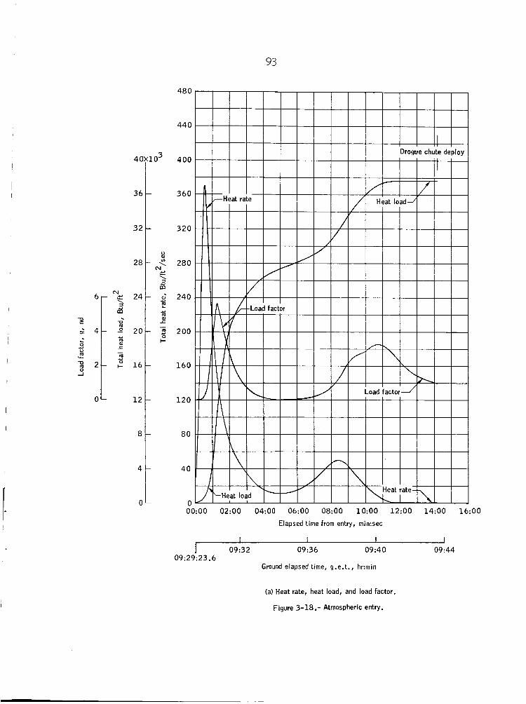
93
6 ~
I
U
I 2 4 L
.-8 0
P a 2 c -0
1
0
40
36
32
28
- 24 s s D
. = 20 Y
ar 1 - m
. $ 16 Y
12
8
4
0
480
440
to3 400
360
320
u
< 280 'v,
65 2 240 L?
5 e
Y
al r - 2 200 I-
160
120
80
40
n 6O:OO 02:OO 04:OO 06:OO 08:OO 1O:OO 12:OO 14:OO 16:OO
Elapsed time from entry, min:sec
I 09:32 09:36 09:40 09:44 09:29:23.6
Ground elapsed time, g.e.t., hr:min
(a) Heat rate, heat load, and load factor.
Figure 3-18.- Atmospheric entry.
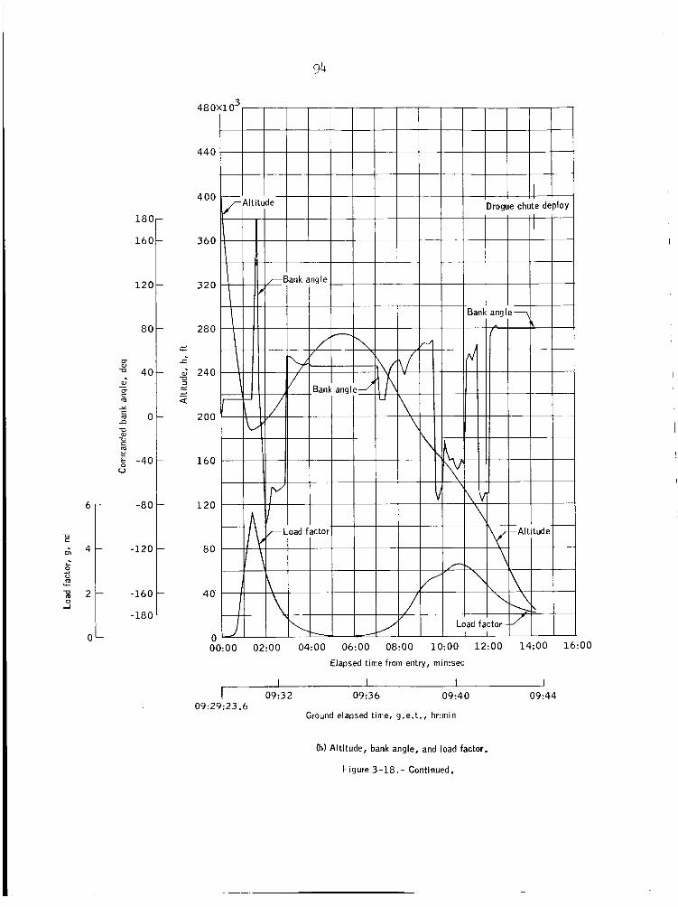
18C
160
120
80
m
40 a, - or m Y
n 5 0
E
U U
-40 0
-80
-120
m L
-160
-180
94
48 0:
440
400
360
320
280
.d L
-c
. 2 240 U .d
.d
._ - U
200
160
120
80
40'
0 0O:OO 02:OO 04:OO 06:OO 08:OO 1O:OO 12:OO 14:OO 1 6 : O O
Elapsed time from entry, rnin:sec
I I I I 09:32 09:36 09:40 09:44
09:29:23.6 Ground elapsed time, g.e.t., hr:min
(b) Altitude, bank angle, and load factor.
F igure 3-18.- Continued.

95
I I I I I I I 1- 0 0. 00 h \o m m N N N N
m N H X m m L n m
6ap IP+ 'apni!iei q a p o a g m 0 z- 8 3 v E 5 "
11 '4 'aPni!llV


97


99
6ap ~ $ u e yueg I I I I I I 1 I I I
0- -I." 0. 0
.- "i c
E
u' V
c 0 W m c m
- E .- L
-0 c m W m c m Y c m
c
-
m s -
d W 3 I=
c 0 u
.- c
I
5 m

l.00
-180 - OO:OO 02:OO 04:OO 06:OO 08:OO 1O:OO 12:OO 14:OO 16:OO 18:oO 20:OO 22:OO
Elapsed time from entry, min:sec I I I I I I I I I I
09:32 09:36 09:40 09: 44 09:48 I Ground elapsed time. g.e. t . , hr:min
09:49:44.9 09:29:23.6
Ih) IMU glmbal angles.
Figure 3-18. - Concluded.

101
m 0
0 0 0 0 0 0 0 0 VI 0 Ln
0 0 0 0 0 d- m m (v (v rl rl
11 'Y 'aP"l!W

102
130 140 150 160
Figure 4-1.-
,
A'
170 180 170 160 150 140 130 120 110 100 East West
Longitude, deg
Spacecraft landing footprint - no second SFS burn.
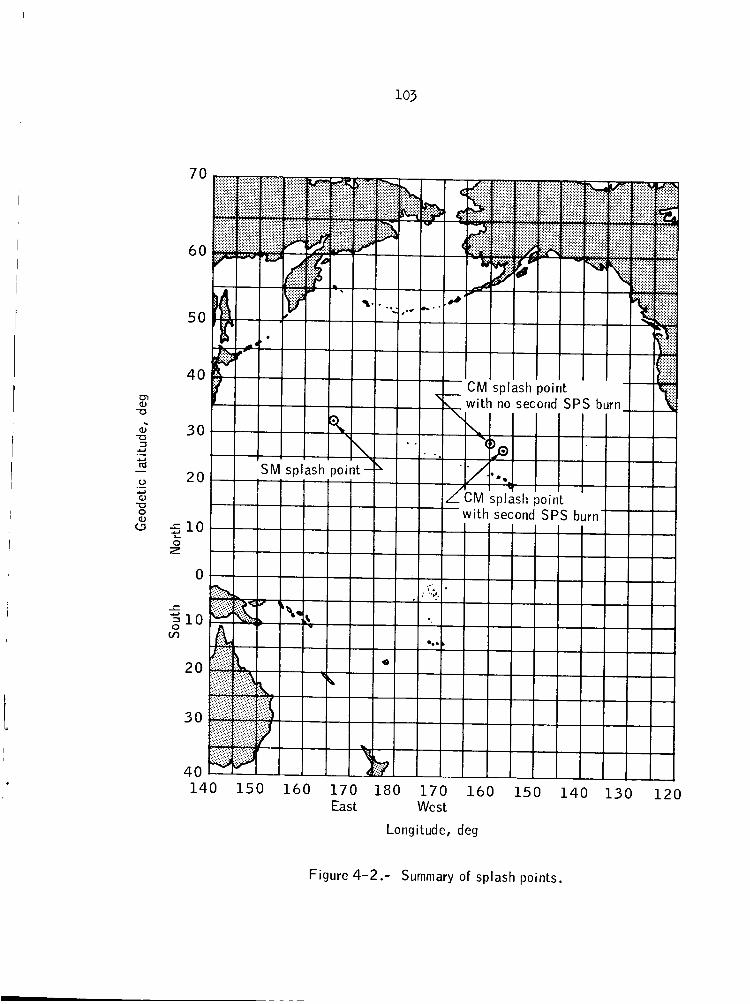
01 a,
T J 5
a, -a 3 U
U m u a, -0 0 a,
.- - .- U
a 1 5 L
0 z
70
60
50
40
30
20
1 0
0
1 0
20
30
40 140 150 160 170 180 170 1 6 0 150 140 130 120
Longitude, deg
East West
Figure 4-2.- Summary of splash points.

104 0 m 3 R 0 R s

0 R 0 N 0 m
i

0 Q 0 'I 0 0 N
106 0 N 0 =s
107
REFERENCES
i
1. Bennett , W i l l i a m J . ; Moore, Ronny H . ; and Sco t t , Walter, Jr. : Spacecraft Reference Tra jec tory , Volume I , 11, 111,: MSC I N 66-FM-67. Ju ly 7 , 1966.
AS-502
2. NASA: Apollo 4 and 6 Mission Requirements. Revision, NM 9-4810, September 27, 1967.
3. Boeing: Saturn V , AS-502 Launch Vehicle Operational F l igh t Tra jec tory F ina l Volumes I and 11, Boeing Company. December 12, 1967.
4. Memo: The l a t e s t on AS-502/020, Apollo 6. Mission Design Manager Memo 6 8 - ~ ~ - ~ - 1 2 . January 21 1968.
5. Memo: Revision #2 t o t h e Apollo Mission Data Spec i f i ca t ion (AMDS) "D" f o r AS-502. PD/Chief, Systems Engineering Divis ion Memo PD7/M-283/67.
6. TRW: Apollo Mission Data Spec i f i ca t ion "D". Apollo Saturn 501 (U). TRW No. 2131-H009-R8-000, Confidential .
7. F l igh t Software Branch: S t a t i o n Charac t e r i s t i c s for Apollo Mission Support. F l i g h t Support Div is ion , May 1967.
e
8. Apollo Missions and Navigation Systems C h a r a c t e r i s t i c s . Technical Report #AN-1.3. December 15 , 1967.
9 . MIT: Guidance System Operational Plan, AS-501, Volume I. MIT R-537, Revision 1. December 1966.
10. Kotanchik, Joseph N . : Apollo 6 Launch Time Versus Heat Shie ld Test Degradation and Minimum Temperature Deviation. February 23, 1968.
MSC Memo ES161/2-23/99 ,
11. TRW: AS-502 Cold Soak Att i tude for December 1, 1967. TRW I O C 3423.9-46, J u l y 27, 1967.
12. TRW: AS-502 Cold Soak At t i tude f o r March 1 t o March 1 5 , 1968. TRW I O C 3421.5-30 , January 11 , 1968.
13. Reed, Robert C. , Jr. : Apollo Command Module ( C M ) Entry A i r Radiation Heating Rates. MSC Memo ES5-1-9/6MY January 9 , 1968.
1 4 . TRW Systems: Operational Trajectory f o r Mission A-2/CSM 020 (Apollo 6 ) , Reentry Phase. T R W Document 67-FMT-590 , February 16 , 1968.
MSC 7512-68