apltcl024 sgd l-01 - · pdf filecompetent in all learni ng outcomes. consequently, activities...
TRANSCRIPT

Elec
tric
al F
unda
men
tals
Stud
ent G
uide

Caterpillar Service Technician ModuleAPLTCL024 ELECTRICAL FUNDAMENTALS
Published by Asia Pacific Learning1 Caterpillar DriveTullamarine Victoria Australia 3043
Version 3.2, 2003
Copyright © 2003 Caterpillar of Australia Pty Ltd Melbourne, Australia.
All rights reserved. Reproduction of any part of this work without the permission of the copy-right owner is unlawful. Requests for permission or further information must be addressed to the Manager, Asia Pacific Learning, Australia.
This subject materials is issued by Caterpillar of Australia Pty Ltd on the understanding that:
1. Caterpillar of Australia Pty Ltd, its officials, author(s), or any other persons involvedin the preparation of this publication expressly disclaim all or any contractual,tortious, or other form of liability to any person (purchaser of this publication or not)in respect of the publication and any consequence arising from its use, includingany omission made by any person in reliance upon the whole or any part of thecontents of this publication.
2. Caterpillar of Australia Pty Ltd expressly disclaims all and any liability to any personin respect of anything and of the consequences of anything done or omitted to bedone by any such person in reliance, whether whole or partial, upon the whole orany part of the contents of this subject material.
Acknowledgements
A special thanks to the Caterpillar Family for their contribution in reviewing the curricula for this program, in particular:
Caterpillar engineers and instructors
Dealer engineers and instructors
Caterpillar Institutes.

MODULE INTRODUCTION
APLTCL024
© Caterpillar of Australia Pty Ltd 1
Module TitleElectrical Fundamentals.
Module DescriptionThis module covers the knowledge and skills of Electrical Fundamentals. Upon satisfactory completionof this module students will be able to competently service and repair basic electrical circuits.
Pre-RequisitesThe following must be completed prior to delivery of this module:
Occupational Health & Safety Procedures
Workplace Tools.
Learning & DevelopmentDelivery of this facilitated module requires access to the Electrical Fundamentals Activity Workbook, arelevant workplace or simulated workplace environment and equipment to develop/practice the skills.
Suggested ReferencesElectrical Schematic for 988B
SMHS7531 Special Instruction - Use of 6V3000 Sure Seal Repair Kit
SEHS9615 Special Instruction - Servicing DT Connectors
SEHS9065 Special Instruction - Use of CE/VE Connector Tools
RENR 2140 9509 Electrical Schematic.
Resource9U7330 Digital Multimeter
Electrical test bench
Video SEVN3197 - Basic Wire Maintenance
6V3000 Sure Seal Repair Kit
IU5805 Deutsch Crimp Tool
IU5804 Deutsch Crimp Tool
Special Instruction SEHS8038 Use of VE Connector Tool Group
Special Instruction SMHS7531 Use of 6V3000 Sure-Seal Repair Kit
Special Instruction SEHS9615 Servicing DT Connectors
4C3806 Deutsch Connector Kit
9U7246 Deutsch DT Connector Kit
Special Instruction SEHS9065 Use of CE/VE Connector Tools
8T5319 Removal Tool Gp
4C4075 Crimp Tool Gp
IU5804 Crimp tool Gp
Deutsch Rectangular Connectors (ARC) (QTY).

ELECTRICAL FUNDAMENTALS MODULE INTRODUCTION
APLTCL024
2 © Caterpillar of Australia Pty Ltd
Assessment Methods
Classroom and WorkshopTo demonstrate satisfactory completion of this module, students must show that they arecompetent in all learning outcomes. Consequently, activities and assessments will measure all thenecessary module requirements.
For this module, students are required to participate in classroom and practical workshop activitiesand satisfactorily complete the following:
Activity Workbook
Knowledge Assessments
Practical Activities.
WorkplaceTo demonstrate competence in this module students are required to satisfactorily complete theWorkplace Assessment(s).

KNOWLEDGE AND SKILLS ASSESSMENT
ELECTRICAL FUNDAMENTALS
APLTCL024
© Caterpillar of Australia Pty Ltd 3
Learning Outcome 1: Explain how electricity works and describe electrical fundamentals.
Assessment Criteria1.1 Define fundamental electrical terminology:
1.1.1 Matter and elements
1.1.2 Atoms
1.1.2.1 Neutron
1.1.2.2 Proton
1.1.2.3 Electron
1.1.3 Explain positively charged and negatively charged atoms
1.1.4 Electrical energy
1.1.5 Define charges and electrostatic field
1.2 Explain electrical terms:
1.2.1 Potential difference
1.2.1.1 Voltage
1.2.1.2 Counter EMF (back EMF)
1.2.2 Coulomb
1.2.3 Current
1.2.3.1 Conventional versus Electron flow
1.2.4 Resistance
1.2.4.1 Physical dimension of materials
1.2.4.2 Measurement of resistance
1.2.4.3 Length
1.2.4.4 Width
1.2.4.5 Temperature
1.2.5 Farad
1.2.6 Hertz
1.3 Explain electrical circuits
1.3.1 Interconnecting path
1.3.2 Kirchoff’s Law of current
1.3.3 Kirchoff’s Law of voltage
1.3.4 Ohm’s Law
1.3.5 Conductors
1.3.5.1 Conductivity of differing materials
1.3.6 Insulators
1.3.6.1 Insulating effect of differing materials
1.3.7 Semiconductors
ELECTRICAL FUNDAMENTALS KNOWLEDGE AND SKILLS ASSESSMENT
APLTCL024
4 © Caterpillar of Australia Pty Ltd
1.4 Describe the construction of different types of magnets
1.4.1 Natural
1.4.2 Artificial
1.4.3 Electromagnets
1.5 Explain magnetic terminology
1.5.1 Poles
1.5.2 Magnetic fields
1.5.3 Lines of force
1.5.4 Magnetic flux
1.5.5 Magnetic force
1.6 Explain electromagnetic induction
1.6.1 Basic concepts
1.6.2 Strength of induction
1.6.2.1 Strength of magnetic field
1.6.2.2 Speed and motion
1.6.2.3 Number of conductors
1.6.3 Voltage induction
1.6.3.1 Generated voltage
1.6.3.2 Self-induction
1.6.3.3 Mutual induction.
Learning Outcome 2: Identify and explain the function of basic electrical components.
Assessment Criteria2.1 Identify and explain the function of basic electrical components:
2.1.1 Wire
2.1.1.1 Solid
2.1.1.2 Fusible links
2.1.1.3 Stranded
2.1.1.4 Twisted/shielded cable
2.1.1.5 Wire gauge
2.2 Wiring harness
2.2.1 Connectors
2.2.1.1 Purpose
2.2.1.2 General Service
2.2.1.3 Plating
2.2.1.4 Contaminants
2.2.1.5 Vehicular Environmental (VE) connectors
2.2.1.6 Sure-seal connectors
2.2.1.7 Deutsch Connectors
2.2.1.8 Caterpillar Environmental Connectors (CE)

ELECTRICAL FUNDAMENTALS KNOWLEDGE AND SKILLS ASSESSMENT
APLTCL024
© Caterpillar of Australia Pty Ltd 5
2.2.2 Terminals
2.2.2.1 Slide
2.2.2.2 Bullet
2.2.2.3 Crimp and soldered
2.2.2.4 Install a solderless connection
2.2.3 Switches
2.2.3.1 Single pole, single throw
2.2.3.2 Single pole, double throw
2.2.3.3 Double pole, single throw
2.2.3.4 Double pole, double throw
2.2.3.5 Common Switches
– Toggle
– Rotary
– Rocker
– Push-on
– Pressure
– Magnetic
– Key start
– Limit
– Cut-out
2.2.4 Circuit protectors
2.2.4.1 Fuses
– Blade
– Cartridge
– Ceramic
– In-line
2.2.4.2 Fusible link
2.2.4.3 Circuit breakers
– Cycling
– Non-cycling
2.2.5 Relays
2.2.6 Solenoids
2.2.7 Resistors
2.2.7.1 Fixed resistors
2.2.7.2 Wattage
2.2.7.3 Rating
2.2.7.4 Variable resistors
2.2.7.5 Thermistors
2.2.7.6 Failed resistors
2.2.8 Capacitor
2.2.8.1 Energy storage
2.2.8.2 Smoothing
2.2.8.3 Suppression
2.2.8.4 Capacitor measurement

ELECTRICAL FUNDAMENTALS KNOWLEDGE AND SKILLS ASSESSMENT
APLTCL024
6 © Caterpillar of Australia Pty Ltd
2.2.9 Lamps
2.2.9.1 Types of bulbs
– Common
– Festoon
– Panel
– Sealed beams
– Prefocus bulbs
– Quartz halogen bulbs
– Precautions fitting quartz halogen bulbs
2.2.9.2 Bulb wattage
2.2.9.3 Candlepower
2.2.10 Instruments
2.2.10.1 Mechanical
2.2.10.2 Magnetic operation
2.2.10.3 Thermal operation
2.2.10.4 Digital electronic
2.2.10.5 Indicators and warning lights.
Learning Outcome 3: Describe the operation of a basic electrical circuit.
Assessment Criteria3.1 Describe the construction of a basic electrical circuit
3.1.1 Power source
3.1.2 Protection device (fuse or circuit breaker)
3.1.3 Load
3.1.4 Control device (switch)
3.1.5 Conductors
3.2 Explain the general rules of Ohm’s Law
3.2.1 Ohm’s Law equation
3.2.2 Ohm’s Law solving circle
3.2.2.1 Voltage unknown
3.2.2.2 Resistance unknown
3.2.2.3 Current unknown
3.3 Define metric prefixes used in electrical circuits
3.3.1 Base units
3.3.1.1 Volts
3.3.1.2 Ohms
3.3.1.3 Amperes
3.3.2 Prefixes
3.3.2.1 Mega
3.3.2.2 Kilo
3.3.2.3 Milli
3.3.2.4 Micro

ELECTRICAL FUNDAMENTALS KNOWLEDGE AND SKILLS ASSESSMENT
APLTCL024
© Caterpillar of Australia Pty Ltd 7
3.4 Calculate power in a circuit using Watt’s Law
3.4.1 What is power
3.4.2 Calculate power
3.5 Explain basic circuit theory
3.5.1 Series circuit
3.5.1.1 Applying Ohm’s Law
3.5.2 Parallel circuit
3.5.2.1 Applying Ohm’s Law
3.5.3 Series-parallel circuit
3.5.3.1 Applying Ohm’s Law.
Learning Outcome 4: Interpret basic electrical schematics.
Assessment Criteria4.1 Identify component symbols in an electrical schematic
4.1.1 Battery
4.1.2 Ground
4.1.3 Wire
4.1.4 Connectors
4.1.5 Switches
4.1.5.1 Connect/disconnect
4.1.5.2 Toggle
4.1.5.3 Temperature
4.1.5.4 Pressure
4.1.6 Circuit protection
4.1.6.1 Fuses
4.1.6.2 Fusible links
4.1.6.3 Circuit breakers
4.1.7 Relays
4.1.8 Solenoids
4.1.9 Transistor
4.1.10 Resistors
4.1.11 Rheostat
4.1.12 Potentiometer
4.1.13 Alternator
4.1.14 Starter
4.1.15 Motor
4.1.16 Lamps
4.1.17 Gauges

ELECTRICAL FUNDAMENTALS KNOWLEDGE AND SKILLS ASSESSMENT
APLTCL024
8 © Caterpillar of Australia Pty Ltd
4.2 Identify electrical schematic features
4.2.1 Colour codes for circuit identification
4.2.2 Colour abbreviation codes
4.2.3 Symbol description
4.2.4 Wiring harness information
4.2.5 Schematic notes and conditions
4.2.6 Grid design for component location
4.2.7 Component part numbers
4.2.8 Dashed coloured lines
4.2.9 Heavy double dashed lines
4.2.10 Thin black dashed line
4.2.11 Machine electrical schematics for old and new format
4.2.12 Features on the back of the schematic.
Learning Outcome 5: Identify electrical measurements using a Digital Multimeter.
Assessment Criteria5.1 Identify the main parts of a Digital Multimeter
5.1.1 Liquid crystal display
5.1.2 Push buttons
5.1.3 Rotary switch
5.1.4 Meter lead inputs
5.1.5 Overload display indicator
5.2 Measure AC/DC Voltage using a Digital Multimeter
5.2.1 Voltmeter must always be connected in parallel
5.2.2 Circuit is on
5.2.3 Position of leads in the multimeter
5.2.4 Rotary switch
5.2.5 Position of leads in the circuit
5.3 Measure voltage drop using a Digital Multimeter
5.3.1 Source voltage
5.3.2 Closed switch contacts
5.3.3 Circuit under power
5.4 Measure AC/DC Current using a Digital Multimeter
5.4.1 Voltmeter must always be connected in series
5.4.2 Burden voltage
5.4.3 Rotary switch
5.4.4 Position of leads in the multimeter
5.4.4.1 Initial placement to determine current output
5.4.4.2 Buffer
5.4.5 Create an open circuit
5.4.6 Position of leads in the circuit
5.4.7 Apply power to circuit

ELECTRICAL FUNDAMENTALS KNOWLEDGE AND SKILLS ASSESSMENT
APLTCL024
© Caterpillar of Australia Pty Ltd 9
5.5 Measure resistance using a Digital Multimeter
5.5.1 Turn off circuit power
5.5.2 Discharge all capacitors
5.5.3 Isolate the circuit
5.5.4 Test lead resistance
5.5.5 Position of leads in multimeter
5.5.6 Rotary switch
5.5.7 Position of leads in the circuit or on component.
Learning Outcome 6: Identify faults in an electrical circuit.
Assessment Criteria6.1 Identify various faults that may occur in an electrical circuit
6.1.1 Open circuit
6.1.2 Short circuit
6.1.3 Grounded circuit
6.1.4 High resistance
6.1.5 Intermittent condition.
Learning Outcome 7: Identify soldering techniques on electrical equipment.
Assessment Criteria7.1 Identify personal safety precautions when soldering.
7.2 Explain the properties of solder
7.2.1 Types
7.2.2 Wetting action
7.2.3 Flux
7.3 Identify types of soldering irons used to solder electrical components
7.3.1 Controlling heat
7.3.2 Thermal mass
7.3.3 Surface condition
7.3.4 Thermal linkage
7.4 Identify the requirements for applying solder
7.4.1 Applying solder
7.4.2 Post solder cleaning
7.4.3 Resoldering
7.4.4 Quality of work
7.5 Identify the need for wire preparation when soldering electrical connections
7.5.1 Stripping away insulation
7.5.2 Nicks, breaks and cuts
7.5.3 Discolouration
7.5.4 Tinning.

ELECTRICAL FUNDAMENTALS KNOWLEDGE AND SKILLS ASSESSMENT
APLTCL024
10 © Caterpillar of Australia Pty Ltd
Learning Outcome 8: Perform electrical measurements using a digital multimeter andrepair faults to an electrical circuit.
Assessment Criteria8.1 State and follow the safety precautions that must be observed
to prevent personal injury or damage to equipment
8.2 Identify and state the purpose of the parts of a digital multimeter
8.2.1 Liquid crystal display (LCD)
8.2.2 Push buttons
8.2.3 Rotary switch
8.2.4 Test lead jacks
8.3 Explain how to read the scales and connect the leads to a digital multimeter
8.3.1 For measuring AC/DC voltage
8.3.2 For measuring voltage drop
8.3.3 For measuring direct current
8.3.4 For measuring resistance
8.4 Connect a multimeter to an operating electrical circuit, measure electrical values and determine repair action
8.4.1 AC/DC voltage
8.4.2 Voltage drop
8.4.3 Direct current
8.4.4 Resistance
8.4.5 Open circuit
8.4.6 Short circuit
8.4.7 Faulty ground
8.5 Conduct minor repairs on an electrical circuit
8.5.1 Fuse replacement
8.5.2 Bulb replacement
8.5.3 Terminal and wire repairs
8.5.4 Open, short circuits and faulty ground
8.6 Facilitators are to ensure that the tasks are completed
8.6.1 Without causing damage to components or equipment
8.6.2 Using appropriate tooling, techniques and materials
8.6.3 According to industry/enterprise guidelines, proceduresand policies
8.6.4 Using and interpreting correct information from themanufacturer’s specifications.

TABLE OF CONTENTS
ELECTRICAL FUNDAMENTALS
APLTCL024
© Caterpillar of Australia Pty Ltd 11
TOPIC 1: Electrical Fundamentals . . . . . . . . . . . . . . . . . . . . . . . . . . 13Fundamentals . . . . . . . . . . . . . . . . . . . . . . . . . . . . . . . . . . . . . . . . . . . . . . . . . . . . . . . . . . 13
Electrical Terms . . . . . . . . . . . . . . . . . . . . . . . . . . . . . . . . . . . . . . . . . . . . . . . . . . . . . . . . 17
Electrical Circuits and Laws . . . . . . . . . . . . . . . . . . . . . . . . . . . . . . . . . . . . . . . . . . . . . . . 22
Magnetism . . . . . . . . . . . . . . . . . . . . . . . . . . . . . . . . . . . . . . . . . . . . . . . . . . . . . . . . . . . . 24
Magnetic Terminology . . . . . . . . . . . . . . . . . . . . . . . . . . . . . . . . . . . . . . . . . . . . . . . . . . . . 25
Electromagnetic Induction . . . . . . . . . . . . . . . . . . . . . . . . . . . . . . . . . . . . . . . . . . . . . . . . 27
TOPIC 2: Electrical Components . . . . . . . . . . . . . . . . . . . . . . . . . . . 31Wire . . . . . . . . . . . . . . . . . . . . . . . . . . . . . . . . . . . . . . . . . . . . . . . . . . . . . . . . . . . . . . . . . 31
Connectors . . . . . . . . . . . . . . . . . . . . . . . . . . . . . . . . . . . . . . . . . . . . . . . . . . . . . . . . . . . . 35
Terminals . . . . . . . . . . . . . . . . . . . . . . . . . . . . . . . . . . . . . . . . . . . . . . . . . . . . . . . . . . . . . 43
Install a Solderless Connection . . . . . . . . . . . . . . . . . . . . . . . . . . . . . . . . . . . . . . . . . . . . 44
Switches . . . . . . . . . . . . . . . . . . . . . . . . . . . . . . . . . . . . . . . . . . . . . . . . . . . . . . . . . . . . . . 51
Circuit Protectors . . . . . . . . . . . . . . . . . . . . . . . . . . . . . . . . . . . . . . . . . . . . . . . . . . . . . . . 53
Relay . . . . . . . . . . . . . . . . . . . . . . . . . . . . . . . . . . . . . . . . . . . . . . . . . . . . . . . . . . . . . . . . . 56
Solenoid . . . . . . . . . . . . . . . . . . . . . . . . . . . . . . . . . . . . . . . . . . . . . . . . . . . . . . . . . . . . . . 56
Resistors . . . . . . . . . . . . . . . . . . . . . . . . . . . . . . . . . . . . . . . . . . . . . . . . . . . . . . . . . . . . . . 57
Capacitor . . . . . . . . . . . . . . . . . . . . . . . . . . . . . . . . . . . . . . . . . . . . . . . . . . . . . . . . . . . . . 61
Lamp Bulbs . . . . . . . . . . . . . . . . . . . . . . . . . . . . . . . . . . . . . . . . . . . . . . . . . . . . . . . . . . . . 62
Instruments . . . . . . . . . . . . . . . . . . . . . . . . . . . . . . . . . . . . . . . . . . . . . . . . . . . . . . . . . . . . 65
TOPIC 3: Electrical Circuits. . . . . . . . . . . . . . . . . . . . . . . . . . . . . . . . 69Basic Circuit Elements . . . . . . . . . . . . . . . . . . . . . . . . . . . . . . . . . . . . . . . . . . . . . . . . . . . 69
Metric Prefixes . . . . . . . . . . . . . . . . . . . . . . . . . . . . . . . . . . . . . . . . . . . . . . . . . . . . . . . . . 72
Power . . . . . . . . . . . . . . . . . . . . . . . . . . . . . . . . . . . . . . . . . . . . . . . . . . . . . . . . . . . . . . . . 74
Basic Circuit Theory . . . . . . . . . . . . . . . . . . . . . . . . . . . . . . . . . . . . . . . . . . . . . . . . . . . . . 74
TOPIC 4: Electrical Schematics . . . . . . . . . . . . . . . . . . . . . . . . . . . . 83Schematics . . . . . . . . . . . . . . . . . . . . . . . . . . . . . . . . . . . . . . . . . . . . . . . . . . . . . . . . . . . . 83
TOPIC 5: Digital Multimeter . . . . . . . . . . . . . . . . . . . . . . . . . . . . . . . . 87Introduction to Digital Multimeters . . . . . . . . . . . . . . . . . . . . . . . . . . . . . . . . . . . . . . . . . . 87
TOPIC 6: Circuit Faults . . . . . . . . . . . . . . . . . . . . . . . . . . . . . . . . . . . 97Circuit Faults . . . . . . . . . . . . . . . . . . . . . . . . . . . . . . . . . . . . . . . . . . . . . . . . . . . . . . . . . . . 97
TOPIC 7: Soldering. . . . . . . . . . . . . . . . . . . . . . . . . . . . . . . . . . . . . . 101Soldering . . . . . . . . . . . . . . . . . . . . . . . . . . . . . . . . . . . . . . . . . . . . . . . . . . . . . . . . . . . . 101
Properties of Solder . . . . . . . . . . . . . . . . . . . . . . . . . . . . . . . . . . . . . . . . . . . . . . . . . . . . 102
Procedure Example . . . . . . . . . . . . . . . . . . . . . . . . . . . . . . . . . . . . . . . . . . . . . . . . . . . . 109

ELECTRICAL FUNDAMENTALS TABLE OF CONTENTS
APLTCL024
12 © Caterpillar of Australia Pty Ltd
ELECTRICAL FUNDAMENTALS
APLTCL024
© Caterpillar of Australia Pty Ltd 13
TOPIC 1Electrical Fundamentals
FUNDAMENTALS
Electricity
Figure 1
What is electricity? It is said that flashlights, electric drills, motors, etc. are generallyrecognised as “electric”. However, computers and televisions are often referred to as“electronic”. What is the difference? Anything that works with electricity is electric,including both flashlights and electric drills, but not all electric components areelectronic. The term electronic refers to semiconductor devices known as “electrondevices”. Electron devices are named as such because they depend on the flow ofelectrons for their operation.
To better understand electricity, it is necessary to have a basic knowledge of thefundamental atomic structure of matter. Matter is anything that has mass and occupiesspace. It can take several forms, or states, such as the three common forms; beingsolid, liquid and gas.
This module will provide a basic understanding of the theoretical principles neededbefore studying and working with electrical circuits and components.

APLTCL024
14 © Caterpillar of Australia Pty Ltd
ELECTRICAL FUNDAMENTALS
Matter and ElementsMatter is anything that takes up space and, when subjected to gravity, has weight.Matter consists of extremely tiny particles grouped together to form atoms. There areapproximately 100 different naturally occurring atoms called elements. An element isdefined as a substance that cannot be decomposed any further by chemical action.Examples of natural elements are copper, lead, iron, gold and silver.
Other elements (approximately 14) have been produced in the laboratory. Elementscan only be changed by an atomic or nuclear reaction. However, they can becombined to make the countless number of compounds which we experience everyday. The atom is the smallest particle of an element that still has the samecharacteristics as the element. Atom is the Greek word meaning a particle too smallto be subdivided.
AtomsAlthough an atom cannot be seen, its hypothetical structure fits experimental evidencethat can be measured very accurately. The size and electric charge of the invisibleparticles in an atom are indicated by how much they are deflected by known forces.The present “solar system” model, with the sun at its centre and the planets rotatingaround it was proposed by Niels Bohr in 1913 and known as the “Atomic Model”.
Figure 2 - Atom
The centre of an atom (Figure 2) is called the nucleus and is composed of particlescalled protons and neutrons. Orbiting around every nucleus are small particles calledelectrons, which are much smaller in mass than either the proton or neutron.Normally, an atom has an equal number of protons and electrons. The number ofprotons or electrons indicates the “atomic number”. The “atomic weight” of an elementis the total of protons and neutrons.

ELECTRICAL FUNDAMENTALS
APLTCL024
© Caterpillar of Australia Pty Ltd 15
Figure 3 - Neutron, Proton, Electron.
Figure 3 shows the structure of two of the simpler atoms:
Hydrogen contains 1 proton in its nucleus balanced by 1 electron in its orbit or shell.The atomic number for a hydrogen atom is 1 and its atomic weight is 1 (1 proton).
Helium has 2 protons in its nucleus balanced by 2 electrons in orbit. The atomicnumber for helium is 2 and its atomic weight would be 4 (2 protons + 2 neutrons).
Scientists have discovered many particles in an atom, but for the purpose ofexplaining basic electricity, just three need discussion: electrons, protons andneutrons. An atom of copper is to be used as an example.
Figure 4 - Copper Atom
The nucleus of the atom is not much bigger than an electron, so their size cannotreally be determined. In the copper atom (Figure 4), the nucleus contains 29 protons(+) and 35 neutrons and has 29 electrons (-) orbiting the nucleus. The atomic numberof the copper atom is 29 and the atomic weight is 64.

APLTCL024
16 © Caterpillar of Australia Pty Ltd
ELECTRICAL FUNDAMENTALS
Electron Flow
Figure 5
If a length of copper wire is connected to a positive and negative source, such as abattery (Figure 5), an electron (-) is forced out of orbit and attracted to the positive (+)end of the battery. The atom is now positively (+) charged because it now has adeficiency of electrons (-). It in turn attracts an electron from its neighbour. Theneighbour in turn receives an electron from the next atom, and so on until the lastcopper atom receives an electron from the negative end of the battery.
The result of this chain reaction is that the electrons move through the battery fromthe negative end to the positive end of the battery. The flow of electrons continues aslong as the positive and negative charges from the battery are maintained at eachend of the wire.
Electrical Energy There are two types of forces at work in every atom. Under normal circumstances,these two forces are in balance. The protons and electrons exert forces on oneanother, over and above gravitational or centrifugal forces. It has been determinedthat besides mass, electrons and protons carry an electric charge, and theseadditional forces are attributed to the electric charge that they carry. However, there isa difference in the forces. Between masses, the gravitational force is always one of“attraction” while the electrical forces both “attract” and “repel”. Protons and electronsattract one another, while protons exert forces of repulsion on other protons, andelectrons exert repulsion on other electrons.
Figure 6 - Force between charges
Thus, It appears to be two kinds of electrical charge. Protons are said to be positive(+) and the electrons are said to be negative (-). The neutron as the name implies, isneutral in charge. The directional quality of the electricity, based on the type ofcharge, is called “polarity”. This leads to the basic law of electrostatics which states:
“LIKE charges repel each other and UNLIKE charges attract each other” (Figure 6).

ELECTRICAL FUNDAMENTALS
APLTCL024
© Caterpillar of Australia Pty Ltd 17
Charges and Electrostatics
Figure 7 - Electrostatic field between two charged bodies
The attraction or repulsion of electrically charged bodies is due to an invisible forcecalled an electrostatic field, which surrounds the charged body. Figure 7 shows theforce between charged particles as imaginary electrostatic lines from the positivecharge to the negative charge. The conventional method of representing the lines offorce is for the arrowheads to point from the positive charge toward thenegative charge.
Figure 8 - Electrostatic field between two negatively charged particles
When two like charges are placed near each other, the lines of force repel each otheras shown in Figure 8.
ELECTRICAL TERMS
Potential Difference Because of the force of its electrostatic field, an electric charge has the ability to moveanother charge by attraction or repulsion. The ability to attract or repel is called its“potential”. When one charge is different from the other, there must be a difference inpotential between them.
The sum difference of potential of all charges in the electrostatic field is referred to aselectromotive force (EMF). The basic unit of potential difference is the “Volt” (E)named in honour of Alessandro Volta, an Italian scientist and the inventor of the“Voltaic Pile”, the first battery cell. The symbol for potential is V, indicating the ability todo the work of forcing electrons to move. Because the Volt unit is used, potentialdifference is called “voltage”. There are many ways to produce voltage, includingfriction, solar, chemical, and electromagnetic induction. The attraction of paper to acomb that has been rubbed with a wool cloth is an example of voltage produced byfriction. A photocell, such as on a calculator, would be an example of producingvoltage from solar energy.

APLTCL024
18 © Caterpillar of Australia Pty Ltd
ELECTRICAL FUNDAMENTALS
Counter EMFMagnetic lines of force radiate out from a wire in concentric circles. This process iscaused by the current flowing in the wire, producing a magnetic field. In a straight wirethese lines of force have little effect since they do not cross any other conductor. If thewire is formed into a coil, the lines of force self-induct back into the wire (self-induction). This induced voltage is called back EMF or counter EMF. This is summedup by the following law known as Lenz’s law:
The polarity of the induced EMF is opposite to and opposes the change that create it.
Coulomb A need existed to develop a unit of measurement for electrical charge. A Frenchscientist named Charles Coulomb investigated the law of forces between chargedbodies and adopted a unit of measurement called the “Coulomb”. Written in scientificnotation, one Coulomb = 6.28 x 10¹⁸ electrons or protons. Stated in simpler terms, ina copper conductor, one ampere is an electric current of 6.28 billion electrons passinga certain point in the conductor in one second (motion).
Current
Figure 9 - Current Flow
In electrostatic theories, as discussed earlier, the concern was mainly the forcesbetween the charges. Another theory that needs explaining is that of “motion” in aconductor. The motion of charges in a conductor is defined as an electriccurrent (Figure 9).
An electrostatic field will affect an electron in the same manner as any negativelycharged body. It is repelled by a negative charge and attracted by a positive charge.The drift of electrons or movement constitutes an electric current.
The magnitude or intensity of current is measured in “Amperes”. The unit symbol is“I”. An ampere is a measure of the rate at which a charge is moved through aconductor. One ampere is a coulomb of charge moving past a point in one second.

ELECTRICAL FUNDAMENTALS
APLTCL024
© Caterpillar of Australia Pty Ltd 19
Conventional Versus Electron Flow
Figure 10 - Electron and Conventional Current
There are two ways to describe an electric current flowing through a conductor. Priorto the use of “atomic theory” to explain the composition of matter, scientists definedcurrent as the motion of positive charges in a conductor from a point of positivepolarity to a point of negative polarity. This conclusion is still widely held in someengineering standards and textbooks. Some examples of positive charges in motionare applications of current in liquids, gases and semi conductors. This theory ofcurrent flow has been termed “conventional current” (Figure 10).
With the application of atomic theory, it was determined that current flow through aconductor was based on the flow of electrons (-) or negative charge. Therefore,electron current is in the opposite direction of conventional current and is termed“electron current” (Figure 10).
Either theory can be used, but the more popular “conventional” theory describing currentas flowing from a positive (+) charge to a negative (-) charge will be used in this module.
Resistance George Simon Ohm discovered that for a fixed voltage, the amount of current flowingthrough a material depends on the type and physical dimensions of the material. Allmaterials present some “resistance” to the flow of electrons. If the opposition is small,the material is a conductor, if the opposition is large, it is an insulator.
The Ohm is the unit of electrical resistance and the Greek letter omega (Ω) is itssymbol. A material has a resistance of one Ohm if a potential of one Volt results in acurrent of one Ampere.
Electrical resistance is present in every electrical circuit, components, wires andconnections. As resistance opposes current flow, it changes electrical energy intoother forms of energy, such as heat, light or motion. The resistance of a conductor isdetermined by four factors:

APLTCL024
20 © Caterpillar of Australia Pty Ltd
ELECTRICAL FUNDAMENTALS
Figure 11 - Atomic Structure
1. Atomic structure (free electrons). The more free electrons a material has, theless resistance it offers to current flow (Figure 11).
Figure 12 - Resistance
2. Length. The longer a conductor of the same width, the higher the resistance. If alength of wire is doubled (Figure 12) the greater the resistance between the two ends.
Figure 13
3. Width (cross sectional area). The larger the cross sectional area of a conductor,the lower the resistance (a bigger diameter pipe allows for more water to flow).Halving the cross section (Figure 13), doubles the resistance for any given length.

ELECTRICAL FUNDAMENTALS
APLTCL024
© Caterpillar of Australia Pty Ltd 21
Figure 14
4. Temperature. For most materials, the higher the temperature, the higher theresistance. The chart shown in Figure 14 shows the resistance increasing asthe temperature rises.
FaradThe ability of a capacitor to store electrons is known as capacitance. Capacitance ismeasures in farads (named after Michael Faraday, the discoverer of the principle).One farad in the ability to store 6.28 billion electrons at a 1-Volt charge differential.Most capacitors have much less capacitance than this, so they are rated in picofarads(trillionths of a farad) and microfarads (millionths of a farad).
1 farad = 1F
1 microfarad = 1µF = 0.000001F
1 picofarad = 1ρF = 0.000000000001F.
HertzAlternators produce alternating current which cycles between positive & negative.
The number of cycles per second is called frequency and is measured in Hertz.

APLTCL024
22 © Caterpillar of Australia Pty Ltd
ELECTRICAL FUNDAMENTALS
ELECTRICAL CIRCUITS AND LAWS
Figure 15
An electrical circuit is a path, or group of interconnecting paths, capable of carrying electricalcurrent. It is a closed path (closed circuit) that contains a voltage source or sources.
There are two basic types of electrical circuits, series and parallel (Figure 15). Thebasic series and parallel circuits may be combined to form more complex circuits, butthese combined circuits may be simplified and analysed as the two basic types.
LawsIt is important to understand the laws needed to analyse and diagnose electricalcircuits. They are Kirchoff’s Laws and Ohm’s Law.
Gustav Kirchoff developed two laws for analysing circuits. They are stated as:
1. Kirchoff’s Current Law (KCL) states that the algebraic sum of the currents at anyjunction in an electrical circuit is equal to zero. Simply stated, all the current thatenters a junction is equal to all the current that leaves the junction. None is lost.
2. Kirchoff’s Voltage Law (KVL) states that the algebraic sum of the electromotiveforces and voltage drops around any closed electrical loop is zero. Simply stated,at a particular point in a closed circuit and going around that circuit, adding allthe individual differences in potential, until the starting point was reached, therewould be no extra voltage, and none would be left unaccounted for.
George Simon Ohm discovered the relationship between three electricalparameters - voltage, current and resistance as follows:
The current in an electrical circuit is directly proportional to the voltage and inversely proportional to the resistance.
The relationship can be summarised by a single mathematical equation:
Current =
or stated in electrical units:
Amperes =
When using mathematical equations to express electrical relationships, single lettersare used to represent them. Resistance is represented by the letter R or the Omegasymbol ( ), voltage is represented by the letter E (electromotive force) and current isrepresented by the letter I (intensity of charge).
OHMS law is covered in more detail in Topic 3, Electrical Circuits.
Electromotive ForceResis cetan
----------------------------------------------------------------
VoltsOhms-----------------
Ω

ELECTRICAL FUNDAMENTALS
APLTCL024
© Caterpillar of Australia Pty Ltd 23
Electrical Conductors In electrical applications, electrons travel along a path called a conductor or wire. Theymove by travelling from atom to atom. Some materials make it easier for electrons totravel and they are called “good conductors”. Examples of good conductors are silver,copper, gold, chromium, aluminium and tungsten. A material is said to be a goodconductor if it has many free electrons. The amount of electrical pressure or voltage ittakes to move electrons through a material depends on how free its electrons are.
Although silver is the best conductor it is also expensive. Gold is also a goodconductor, and will not corrode like copper but again, is too expensive. Aluminium isless expensive and lighter, but not as good as a conductor as copper.
Table 1 - Conductivity Chart
The conductivity of a material determines how good a conductor that material is. Table1 shows some of the common conductors and their relative conductivity to copper.
Electrical InsulatorsOther materials make it difficult for electrons to travel and they are called “insulators”.A good insulator keeps the electrons tightly bound in orbit.
Examples of insulators are rubber, wood, plastics, and ceramics. However, it ispossible to make an electric current flow through all materials. If the applied voltage ishigh enough, even the best insulators will break down and allow current flow.
Table 2 - Common Insulators
Table 2 lists some of the more common insulators.
There is another item that should be considered when discussing insulators. Dirt andmoisture may serve to conduct electricity around an insulator. If an insulator is dirty orthere is moisture present, it could cause a problem. The insulator itself is not breakingdown, but the dirt or moisture can provide a path for electrons to flow. It is thereforeimportant to keep the insulators and contacts clean.
Conductor Conductivity (to copper)
Silver 1.064
Copper 1.000
Gold 0.707
Aluminium 0.659
Zinc 0.288
Brass 0.243
Iron 0.178
Tin 0.018
Rubber Plastics
Mica Glass
Wax or Paraffin Fibreglass
Porcelain Dry Wood
Bakelite Air

APLTCL024
24 © Caterpillar of Australia Pty Ltd
ELECTRICAL FUNDAMENTALS
Semi-conductorsMaterials which are neither good conductors nor good insulators are known as semi-conductors. Example of these materials (elements) are Germanium & Silicon. Semi-conductors will normally act as inductors, however, they will conduct under certainconditions, such as when an electrical current is applied to them. These materials arethe basis for electronic devices discussed in the electronic module.
MAGNETISM
Figure 16 - Magnet
Magnetism is another form of force that causes electron flow or current. A basicunderstanding of magnetism is also necessary to study electricity. Magnetismprovides a link between mechanical energy and electricity. By the use of magnetism,an alternator converts some of the mechanical power developed by an engine toelectromotive force (EMF). Conversely, magnetism allows a starter motor to convertelectrical energy from a battery into mechanical energy for cranking the engine.
Most electrical equipment depends directly or indirectly upon magnetism. Althoughthere are a few electrical devices that do not use magnetism, the majority of oursystems, as known today, would not exist.
There are three basic types of magnets:
Natural
Artificial Magnets (Figure 16)
Electromagnets.
Natural Magnets The Chinese discovered magnets about 2637 BC. The magnets used in the primitivecompasses are called “lodestones”, and they were crude pieces of iron ore known asmagnetite. Since magnetite has magnetic properties in its natural state, lodestonesare classified as “natural” magnets.

ELECTRICAL FUNDAMENTALS
APLTCL024
© Caterpillar of Australia Pty Ltd 25
Artificial MagnetsArtificial Magnets are man-made magnets and are typically produced in the form ofmetal bars that have been subjected to very strong magnetic fields.
ElectromagnetsA Danish scientist, named Oersted, discovered a relation between magnetism andelectric current. He discovered that an electric current flowing through a conductorproduced a magnetic field around the conductor. From this, electromagnets can beused in various applications where switching the flow of electricity ‘on’ or ‘off’ willproduce a magnetic field.
MAGNETIC TERMINOLOGY
Poles and Fields
Figure 17 - Field Force around a magnet
Every magnet has two points opposite each other that most readily attract pieces ofiron. These points are called the “poles” of the magnet: the north pole and the southpole. Just as electric charges repel each other and opposite charges attract eachother, like magnetic poles repel each other and unlike poles attract each other.
A magnet clearly attracts a bit of iron because of forces that exists around the magnet.This force is called “magnetic field”.
Although it is invisible to the naked eye, sprinkling small iron filings on a sheet of glassor paper over a bar magnet can show its force lines.
In Figure 17 a piece of glass is placed over a magnet and iron filing are sprinkled onthe glass. When the glass cover is gently tapped the filings will move into a definitepattern which shows the field force around the magnet.
The field seems to be made up of lines of force that appear to leave the magnet at thenorth pole, travel through the air around the magnet, and continue through the magnetto the south pole to form a closed loop of force. The stronger the magnet the greaterthe lines of force and the larger the area covered by the magnetic field.

APLTCL024
26 © Caterpillar of Australia Pty Ltd
ELECTRICAL FUNDAMENTALS
Lines of Force
Figure 18 - Lines of Force
To better visualise the magnetic field without iron filings, the field is shown as lines offorce in Figure 18. The direction of the lines outside the magnet shows the path anorth pole would follow in the field, repelled away from the north pole of the magnetand attracted to its south pole. Inside the magnet, which is the generator for themagnetic field, the lines are from north pole to south pole.
Lines of Magnetic Flux The entire group of magnetic field lines, which can be considered to flow outwardfrom the north pole of a magnet, is called magnetic flux. The flux density is thenumber of magnetic field lines per unit of a section perpendicular to the direction offlux. The unit is lines per square centimetre in the metric system or lines per squareinch in the English system. One line per square centimetre is called a gauss.
Magnetic Force
Figure 19 - Lines of small magnetic circles
Magnetic lines of force pass through all materials; there is no known insulator againstmagnetism. However, flux lines pass more easily through materials that can be magnetisedthan through those that cannot. Materials that do not readily pass flux lines are said to have“high magnetic reluctance”. Air has high reluctance; iron has low reluctance.
An electric current flowing through a wire creates magnetic lines of force around thewire. Figure 19 shows lines of small magnetic circles forming around the wire.Because such flux lines are circular, the magnetic field has no north or south pole.
Figure 20 - Circular Fields
However, if the wire is wound onto a coil, individual circular fields merge. The result isa unified magnetic field with north and south poles as shown in Figure 20.

ELECTRICAL FUNDAMENTALS
APLTCL024
© Caterpillar of Australia Pty Ltd 27
As long as current flows through the wire, it behaves just like a bar magnet. Theelectromagnetic field remains as long as current flows through the wire. However, thefield produced on a straight wire does not have enough magnetism to do work. Tostrengthen the electromagnetic field, the wire can be formed into a coil. The magneticstrength of an electromagnet is proportional to the number of turns of wire in the coiland the current flowing through the wire. If the coils are wound around a metal core,e.g. iron, the magnetic force strengthens considerably.
Types of electromagnets typically used in mobile machines are relays and solenoids.Both operate on the electromagnetic principle, but function differently.
ELECTROMAGNETIC INDUCTION
Figure 21 - Electromagnetic Induction
The effect of creating a magnetic field with current has an opposite condition. It is alsopossible to create current with a magnetic field by ‘inducing’ a voltage in theconductor. This process is known as “electromagnetic induction” (Figure 21). Thisoccurs when the flux lines of a magnetic field cut across a wire (or any conductor).When there is relative motion between the wire and the magnetic field (whether themagnetic field moves or the wire moves), a voltage is induced in the conductor. Theinduced voltage causes a current to flow. When the motion stops, the current stops. Ifa wire is passed through a magnetic field, such as a wire moving across the magneticfields of a horseshoe magnet, voltage is induced.
If the wire is wound into a coil, the voltage induced strengthens. This method is theoperating principle used in speed sensors, generators, and alternators. In some casesthe wire is stationary and the magnet moves. In other cases, the magnet is stationaryand the field windings (wires) move.
Movement in the opposite direction causes current to flow in the opposite direction.Therefore, back and forth motion produces Alternating Current (AC).
In practical applications, multiple conductors are wound into a coil. This concentrates theeffects of electromagnetic induction and makes it possible to generate useful electricalpower with a relatively compact device. In a generator, the coil moves and the magneticfield is stationary. In an alternator, the magnetic field is rotated inside a stationary coil.

APLTCL024
28 © Caterpillar of Australia Pty Ltd
ELECTRICAL FUNDAMENTALS
The strength of an induced voltage depends on several factors:
The strength of the magnetic field
The speed of the relative motion between the field and the coil
The numbers of conductors in the coil.
There are three ways in which a voltage can be induced by electromagnetic induction:
Generated Voltage
Self-Induction
Mutual Induction.
Generated Voltage
Figure 22 - DC Generator
A simple Direct Current (DC) generator in Figure 22 shows a moving conductorpassing a stationary magnetic field to produce voltage and current. A single loop ofwire is rotating between the north and south poles of a magnetic field.
Self-Induction
Figure 23 - Self-Induction
Self-induction occurs in a wire when the current flowing through the wire changes.Current flowing through the wire creates a magnetic field that builds up and collapsesas the current changes up and down. A voltage is thereby induced in the core.Figure 23 shows self-induction in a coil.

ELECTRICAL FUNDAMENTALS
APLTCL024
© Caterpillar of Australia Pty Ltd 29
Mutual Induction
Figure 24 - Mutual Induction
Mutual induction occurs when the changing current in one coil induces a voltagein an adjacent coil. A transformer is an example of mutual induction. Figure 24shows two inductors that are relatively close to each other. When AC currentflows through coil L1 a magnetic field cuts through coil L2 inducing a voltage andproducing current flow in coil L2.

APLTCL024
30 © Caterpillar of Australia Pty Ltd
ELECTRICAL FUNDAMENTALS

ELECTRICAL FUNDAMENTALS
APLTCL024
© Caterpillar of Australia Pty Ltd 31
TOPIC 2Electrical Components
WIRE
Types of Wire
Figure 25
Wires are the conductors for electrical circuits. Wires are also called leads. Most wiresare stranded (made up of several smaller wires that are wrapped together and coveredby a common insulating sheath) (Figure 25).
There are many types of wires found in automotive applications, including:
Copper.
The most common type. Copper wires can be single, however are usually stranded.
Fusible Links.
There are circuit protection devices that are made of a smaller wire than the restof the circuit their purpose is to protect against overload.
Twisted/Shielded Cable.
A pair of small gauge wires, normally stranded, insulated against Radio FrequenciesInterference/Electro Magnetic Interference, used for computer communicationsignals, electronic control modules and other electronic components.

APLTCL024
32 © Caterpillar of Australia Pty Ltd
ELECTRICAL FUNDAMENTALS
Wire GaugeIn the USA, electrical and electronic circuits are engineered with specific size andlength conductors to provide paths for current flow. The size of a wire determines howmuch current it can carry.
Wire sizes can be rated in two different ways:
according to American Wire Gage (AWG) size (usually referred to as simply the“gauge” of the wire)
by metric size.
Table 3 - AWG to Metric Conversion Chart
When repairing or replacing machine wiring it is necessary to use the correct size and lengthconductors. The chart above illustrates the typical resistances for various size conductors.
AWG No Ø (inch) Ø (mm) Ø (mm2)Resistance
(Ohm/m)
4/0 = 0000 0.460 11.7 107 0.000161
3/0 = 000 0.410 10.4 85.0 0.000203
2/0 = 00 0.365 9.26 67.4 0.000256
1/0 = 0 0.325 8.25 53.5 0.000323
1 0.289 7.35 42.4 0.000407
2 0.258 6.54 33.6 0.000513
3 0.229 5.83 26.7 0.000647
4 0.204 5.19 21.1 0.000815
5 0.182 4.62 16.8 0.00103
6 0.162 4.11 13.3 0.00130
7 0.144 3.66 10.5 0.00163
8 0.128 3.26 8.36 0.00206
9 0.114 2.91 6.63 0.00260
10 0.102 2.59 5.26 0.00328

ELECTRICAL FUNDAMENTALS
APLTCL024
© Caterpillar of Australia Pty Ltd 33
Table 4
Table 4 therefore assumes a maximum ambient temperature of 150oF (65oC).
NOTE:Regard PVC insulated wire as a 185oF (85oC) product.
When using the AWG, remember that smaller gauge numbers denote larger wire sizes,and larger gauge numbers denote smaller sizes.
*Max
. Rec
om-
men
ded
Cur
rent
A
mps
)
7 11 12 13 15 20 24 32 59 87
*Bas
ed o
n 36
o F (
20o C
) m
axim
um te
mpe
ratu
re r
ise
abov
e am
bien
t.
Res
ista
nce
(Ω /1
000
met
res
@
25o C 50 36 21 18 12.3
7.3
4.4
3.2
1.75 1.1
Nea
rest
St
anda
rd
Met
ric S
ize
(mm
2 )
0.35 0.5
0.75 1 105
2.5 4 6 10 16
Res
ista
nce
(Ω/1
000
ft @
77
o F)
16.5
10.4 -
6051
4.09
2.58
1.62
1.02
0.64 0.4
Cro
ssSe
ctio
n(c
ircul
ar m
ils)
642
1,02
0
-
1,62
0
2,58
0
4,11
0
6,53
0
10,4
00
16,5
00
26,3
00
Cro
ssSe
ctio
n (In
ch)
0.00
05
0.00
08
-
0.00
127
0.00
203
0.00
323
0.00
817
0.00
817
0.01
296
0.02
03
Am
eric
an
Wire
Gau
ge
(AW
G)
22 20 - 18 16 14 12 10 8 6

APLTCL024
34 © Caterpillar of Australia Pty Ltd
ELECTRICAL FUNDAMENTALS
Wiring HarnessMany wires are bound together in groups with one or more common connectors oneach end. These groups are called wire harnesses. Note that a harness may containwires from different circuits and systems. An example would be the harness that plugsinto the headlight switch assembly, which contains wires for parking lights, tail-lights,and low and high-beam headlights, among others.
Figure 26
Some harness wires are enclosed in plastic or non-conductive fibre conduit(Figure 26). These conduits are split lengthwise to allow easy access to the harnesswires. Other harness wires are wrapped in tape. Clips (plastic) and clamps (metal)attach harnesses to the machine.
Caterpillar electrical schematics provide wire harness locations to help you easilylocate a specific harness on a machine. The features of Caterpillar electricalschematics will be covered later.

ELECTRICAL FUNDAMENTALS
APLTCL024
© Caterpillar of Australia Pty Ltd 35
CONNECTORS
Figure 27
The purpose of a connector is to pass current from one wire to another (Figure 27). In orderto accomplish this, the connector must have two mating halves (plug or receptacle). Onehalf houses a pin and the other half houses a socket. When the two halves are joined,current is allowed to pass. Connecters are used to make component disassembly easier.

APLTCL024
36 © Caterpillar of Australia Pty Ltd
ELECTRICAL FUNDAMENTALS
General Service CommentsWith the increased use of electronic systems in automotive applications, servicingconnectors has become a critical task. With increased usage comes an increase inmaintenance on the wiring, connectors, pins and sockets. Another important factorcontributing to increased repair is the harsh environment in which the connectors operate.Connectors must operate in extremes of heat, cold, dirt, dust, moisture and chemicals.
Figure 28 - Connectors
Pins and sockets have resistance and offer some opposition to current flow. Sincethe surface of the pins and sockets are not smooth (contain peaks and valleys) acondition known as asperity (roughness of surface) exists. When the matinghalves are connected, approximately one percent of the surfaces actually contacteach other (Figure 28).
The electrons are forced to converge at the peaks, thereby creating a resistancebetween the contact halves. Although this process seems rather insignificant to theoperation of an electronic control, a resistance across the connector could create amalfunction in electronic controls.
PlatingIn order to achieve a minimum resistance in the pins and contacts, there needs to beconcern with the finish, pressure and metal used in construction of the pins andcontacts. Tin is soft enough to allow for “film wiping” but it has a relatively highresistance. Copper has a low resistance but is hard. In striving for minimum resistanceand the reduction of asperity, low resistance copper contacts are often plated with tin.
Film wiping occurs when pins and contacts are plated with tin and when they aremated together they have a tendency to “wipe” together and actually smooth outsome of the peaks and valleys created by the asperity condition. Other metals, suchas gold and silver are excellent plating materials, but are too costly to use.
ContaminantsContaminants are another factor that contribute to resistance in connectors. Some harshconditions that employ chemicals, etc. can cause malfunctions due to increased resistance.
Technicians need to be aware that connectors can and do cause many diagnosticproblems. It may be necessary to measure the resistance between connector halveswhen diagnosing electrical control malfunctions. Also, technicians need to be awarethat disconnecting and reconnecting connectors during the troubleshooting processcan give misleading diagnostic information.

ELECTRICAL FUNDAMENTALS
APLTCL024
© Caterpillar of Australia Pty Ltd 37
Several types of connectors are used throughout the electrical and electronicsystems on automotive machines. Each type differs in the manner in which theyare serviced or repaired.
The following types of connectors will be discussed in detail:
Vehicular Environmental (VE) Connectors
Sure-Seal Connectors
Deutsch Connectors (HD10, DT, CE and DRC Series).
VE Connectors
Figure 29
The VE connector (Figure 29) was used primarily on earlier Caterpillar machineelectrical harnesses where high temperatures, larger number of contacts or highercurrent carrying capacities were needed.
The connector required a special metal release tool for removing the contacts thatcould damage the connector lock mechanism, if the tool was turned duringrelease of the retaining clip.
Do not use these metal release tools for any other type of electrical connector.
After crimping a wire to the contact it is recommended that the contact besoldered to provide for a good electrical contact. Use only rosin core solder onany electrical connection.
Specific information relating to the process required for installing VE connectorcontacts (pins and sockets) is contained in Special Instruction: Use of VE ConnectorTool Group (Form SEHS8038).
This type of connector is no longer used on current product, but may still requireservicing by a field/shop technician.

APLTCL024
38 © Caterpillar of Australia Pty Ltd
ELECTRICAL FUNDAMENTALS
Sure-Seal Connectors
Figure 30
Sure-Seal connectors are used extensively on Caterpillar machines (Figure 30).
These connector housings have provisions for accurate mating between the twohalves, but instead of using guide keys or key ways, the connector bodies aremoulded such that they will mate correctly.
Sure-Seal Connectors are limited to a capacity of 10 contacts (pins and sockets).
Part numbers for spare plug and receptacle housings and contacts are contained inSpecial Instruction: Use of 6V3000 Sure-Seal Repair Kit (Form SMHS7531).
Use special tool (6V3001) for crimping contacts and stripping wires. Sure-SealConnectors require the use of a special tool 6V3008 for installing contacts. Usedenatured alcohol as a lubricant when installing contacts. Special tooling is notrequired for removing pin contacts.
Any holes in the housings not used for contact assemblies should be filled with a 9G3695Sealing Plug. The sealing plug will help prevent moisture from entering the housings.
ELECTRICAL FUNDAMENTALS
APLTCL024
© Caterpillar of Australia Pty Ltd 39
Deutsch Heavy Duty (HD10) Series Connectors
Figure 31
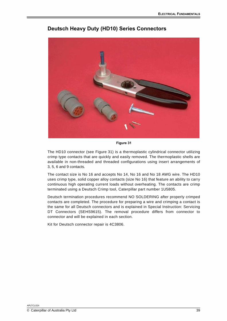
The HD10 connector (see Figure 31) is a thermoplastic cylindrical connector utilizingcrimp type contacts that are quickly and easily removed. The thermoplastic shells areavailable in non-threaded and threaded configurations using insert arrangements of3, 5, 6 and 9 contacts.
The contact size is No 16 and accepts No 14, No 16 and No 18 AWG wire. The HD10uses crimp type, solid copper alloy contacts (size No 16) that feature an ability to carrycontinuous high operating current loads without overheating. The contacts are crimpterminated using a Deutsch Crimp tool, Caterpillar part number 1U5805.
Deutsch termination procedures recommend NO SOLDERING after properly crimpedcontacts are completed. The procedure for preparing a wire and crimping a contact isthe same for all Deutsch connectors and is explained in Special Instruction: ServicingDT Connectors (SEHS9615). The removal procedure differs from connector toconnector and will be explained in each section.
Kit for Deutsch connector repair is 4C3806.

APLTCL024
40 © Caterpillar of Australia Pty Ltd
ELECTRICAL FUNDAMENTALS
Deutsch Transportation (DT) Series Connectors
Figure 32
The DT connector (Figure 32) is a thermoplastic connector utilizing crimp type contactsthat are quickly and easily removed and require no special tooling. The thermoplastichousings are available in configurations using insert arrangements of 2, 3, 4, 6, 8 and 12contacts. The contact size is No 16 and accepts No 14, No 16 and No 18 AWG wire.
The DT uses crimp type, solid copper alloy contacts (size No 16) that feature anability to carry continuous high operating current loads without overheating, orstamped and formed contacts (less costly). The contacts are crimp terminated usinga Deutsch Crimp Tool, Caterpillar part number 1U5804.
The DT connector differs from other Deutsch connectors in both appearance andconstruction. The DT is either rectangular or triangular shaped and containsserviceable plug wedges, receptacle wedges and silicone seals.
The recommended cleaning solvent for all Deutsch contacts is denatured alcohol.
For a more detailed explanation on servicing the DT connector, consult SpecialInstruction: Servicing DT Connectors (SEHS9615).
Kit for servicing DT connectors is Caterpillar part No 9U7246.

ELECTRICAL FUNDAMENTALS
APLTCL024
© Caterpillar of Australia Pty Ltd 41
Caterpillar Environmental Connectors (CE)
Figure 33
The CE connector is a special application connector (Figure 33). The CE Series connectorcan accommodate between 7 and 37 contacts, with the 37 contact connector being usedon various electronic control modules. The CE connector uses two different crimping tools.
The crimping tool for No 4 - No 10 size contacts is a 4C4075 Hand Crimp ToolAssembly, and the tool for No 12 - No 18 contacts is the same tool as used on theHD and DT Series connectors (1U5804).
Reference SEHS9065
8T5319 Removal Tool GP
4C4075 Crimp tool GP
1U5804 Crimp Tool GP.

APLTCL024
42 © Caterpillar of Australia Pty Ltd
ELECTRICAL FUNDAMENTALS
Deutsch Rectangular Connector (DRC)
Figure 34
The DRC connector (Figure 34) features a rectangular thermoplastic housing and iscompletely environmentally sealed. The DRC is best suited to be compatible withexternal and internal electronic control modules.
The connector is designed with a higher number of terminals. The insertarrangements available are: 24, 40 and 70 contact terminations. The contact size isNo 16 and accepts No 16 and No 18 AWG wire.
The connector uses crimp type, copper alloy contacts (size No 16) that feature anability to carry continuous high operating current loads without overheating orstamped and formed contacts (less costly). The contacts are crimp terminated usinga Deutsch Crimp Tool, Caterpillar part number 1U5805.
The connector contains a “clocking” key for correct orientation and is properly secured bya stainless steel jackscrew. A 4mm (5/32in) HEX wrench is required to mate the connectorhalves. The recommended torque for tightening the jackscrew is 25in pounds.
NOTE:The DRC uses the same installation and removal procedures as the HD10 series.
ELECTRICAL FUNDAMENTALS
APLTCL024
© Caterpillar of Australia Pty Ltd 43
TERMINALS
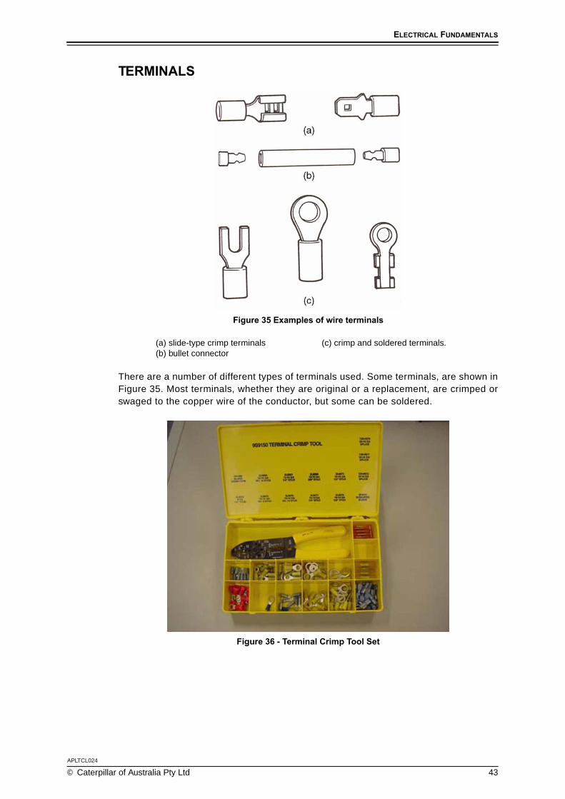
Figure 35 Examples of wire terminals
There are a number of different types of terminals used. Some terminals, are shown inFigure 35. Most terminals, whether they are original or a replacement, are crimped orswaged to the copper wire of the conductor, but some can be soldered.
Figure 36 - Terminal Crimp Tool Set
(a) slide-type crimp terminals(b) bullet connector
(c) crimp and soldered terminals.

APLTCL024
44 © Caterpillar of Australia Pty Ltd
ELECTRICAL FUNDAMENTALS
INSTALL A SOLDERLESS CONNECTIONWhen stripping an electrical wire and joining a solderless connector, the followingpoints are to be considered.
Safety CheckNever use a sharp blade or knife to remove insulation. A sharp blade may cutthrough the wire completely or may cause personal injury.
Wire stripping pliers have sharp edges and require a tight grip. Be careful not totrap your skin between the jaws.
When removing the insulation from wire, push away rather than towards the body.
Points to NoteElectrical wire used in automotive wiring harnesses is covered by an insulatinglayer of plastic.
When electrical wire is joined to other wires or connected to a terminal, theinsulation needs to be removed.
Wire stripping tools come in various configurations. They all perform the sametask. The type of tool used will depend on the amount and type of electrical wireto be repaired.
Solderless terminals require a clean, tight connection, so ensure the wire and theconnection are clean before fitting any terminals.
Use connections that match the size of the wire.
Do not use side cutters, pliers or a knife to strip the wire. Using these tools willdamage some of the wire strands and may break the wire inside the insulation.
To keep the wires together after stripping them, give them a slight twist. Do not twistthe wire too much, otherwise a risk of poor wire-to-terminal connection may occur.
Use the correct crimpling tool for the connection. Using the wrong type of tool willcause the connection to have a poor grip on the wire.
1. Select the Terminal
Figure 37
There are different types and sizes of wire terminals, but the procedure for installingall of them is the same.
This is a bullet type of crimp terminal (Figure 37).

ELECTRICAL FUNDAMENTALS
APLTCL024
© Caterpillar of Australia Pty Ltd 45
Figure 38
Make sure that the correct size of terminal for the wire is selected and that the terminalhas the correct volt/amp rating for the job it will perform (Figure 38).
2. Strip the Wire
Figure 39
Remove an appropriate amount of the protective insulation from the wire (Figure 39).Always use a proper stripping tool that is in good condition.
3. Always Use a Proper Stripping Tool
Figure 40
The purpose of a wire stripping tool is to allow for the removal of insulation fromaround the copper core of a cable without damaging the cable or causingpersonal injury (Figure 40).

APLTCL024
46 © Caterpillar of Australia Pty Ltd
ELECTRICAL FUNDAMENTALS
Figure 41
Using side cutters or pliers (Figure 41) can also be dangerous; they are also lesseffective because they often cut away some of the strands of wire.
Figure 42
This is known as ringing the wire (Figure 42), which effectively reduces the currentcarrying capacity of the wire.
4. Select the Correct Gauge Hole
Figure 43
Using the correct tool is much safer and more effective.
Wire Strippers can remove the insulation from different gauges of cable; select thehole in the stripper that is closest to the diameter of the core in the cable to bestripped. On the wire strippers in Figure 43 above, the size of the wire stripping orificesare indicated on the tool.

ELECTRICAL FUNDAMENTALS
APLTCL024
© Caterpillar of Australia Pty Ltd 47
5. Cut the Insulation
Figure 44
Place the cable in the hole and close the jaws firmly around it to cut the insulation.
If you have selected the right gauge the wire stripper will cut through the insulation butnot through the copper core (Figure 44).
Figure 45
Only remove as much insulation as is necessary to do the job. Too little bare wire maynot achieve a good connection and too much may expose the wire for potential shortcircuit with other circuits or to ground. Removing more than 1.2 centimetres (half aninch) of insulation at a time can also stretch and damage the core (Figure 45).
6. Remove the Insulation
Figure 46
Some strippers automatically cut and remove the insulation.
Others just make the cut and hold the cable tightly (Figure 46). When using this typeof stripper, pull firmly on the wire to remove the insulation.

APLTCL024
48 © Caterpillar of Australia Pty Ltd
ELECTRICAL FUNDAMENTALS
Figure 47
To keep the strands together, give them a light twist (Figure 47).
7. Place the terminal on the wire
Figure 48
There will be a better connection if the strands are not twisted together tightly beforeplacing them through the terminal (Figure 48). When crimped, this gives the terminalmore surface contact area with the wire.
However, it can be difficult to insert the wires into the terminal if they are all justloose strands...
Figure 49
... so twist them together just enough to help insert them cleanly.
Place the bullet or terminal onto the wire (Figure 49).

ELECTRICAL FUNDAMENTALS
APLTCL024
© Caterpillar of Australia Pty Ltd 49
8. Alternative Terminal Types
Figure 50
Some types of crimp terminals do not have an insulation component fixed to them.
These come in two parts and the insulator is supplied as a separate component(Figure 50). In these cases, always make sure that the ‘core’ of the wire to be crimped...
Figure 51
... extends through the ‘core wings’ in the terminal (Figure 51).
9. Select the Crimping Anvil
Figure 52
Use a proper crimping tool for pin or core crimping. DO NOT use pliers. They have atendency to cut through the connection and can give trouble during service.
Select the proper anvil on the crimping tool for the connector or terminal selected.These are usually colour-coded so it is easy to match the terminal with theright size anvil.

APLTCL024
50 © Caterpillar of Australia Pty Ltd
ELECTRICAL FUNDAMENTALS
10. Crimping
Figure 53
Crimp the ‘core’ section first. Use firm pressure so that a good electrical contact willbe made, but not excessive force as this can bend the pin or terminal (Figure 53).
Then crimp the insulation wings or section. This crimp is on the wire insulation to holdthe cable in place, not for electrical contact, so there is no need to crimp this sectionquite as hard.
Figure 54
Give a gentle tug on the finished job to ensure that the connection will holdin service (Figure 54).

ELECTRICAL FUNDAMENTALS
APLTCL024
© Caterpillar of Australia Pty Ltd 51
SWITCHES
Figure 55
A switch (Figure 55) is a device used to complete or interrupt a current path. Typically,switches are placed between two conductors (or wires). There are many different typesof switches, such as Single-Pole Single-Throw (SPST), Single-Pole Double Throw(SPDT), Double-Pole Single-Throw (DPST) and Double-Pole Double-Throw (DPDT).
Figure 56
There are also many ways of actuating switches, the switches shown in Figure 56 aremechanically operated by moving the switch lever or toggle. Sometimes, switches arelinked so that they always open and close at the same time. In schematics, this is shownby connecting linked switches with a dashed line (DPST and DPDT in Figure 56).
Other mechanically operated switches are limit switches and pressure switches. Theswitch contacts are closed or opened by an external means, such as a lever actuatinga limit switch or pressure actuated.
APLTCL024
52 © Caterpillar of Australia Pty Ltd
ELECTRICAL FUNDAMENTALS
Some of the more common switches used on Caterpillar machines are:
Toggle
Rotary
Rocker
Push-On
Pressure
Magnetic
Key Start
Limit
Cutout.
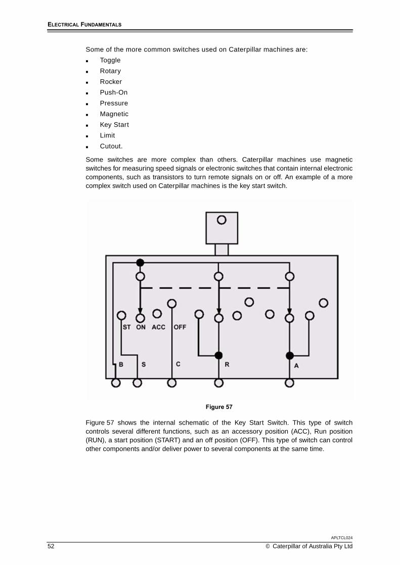
Some switches are more complex than others. Caterpillar machines use magneticswitches for measuring speed signals or electronic switches that contain internal electroniccomponents, such as transistors to turn remote signals on or off. An example of a morecomplex switch used on Caterpillar machines is the key start switch.
Figure 57
Figure 57 shows the internal schematic of the Key Start Switch. This type of switchcontrols several different functions, such as an accessory position (ACC), Run position(RUN), a start position (START) and an off position (OFF). This type of switch can controlother components and/or deliver power to several components at the same time.

ELECTRICAL FUNDAMENTALS
APLTCL024
© Caterpillar of Australia Pty Ltd 53
CIRCUIT PROTECTORS
Figure 58
Fuses and fusible links are circuit protectors. If there is excess current in a circuit, itcauses heat. The heat, not the current, causes the circuit protector to open before thewiring can be damaged.
This has the same effect as turning a switch OFF. Note that circuit protectors (Figure 58)are designed to protect the wiring, not necessarily other components. Fuses and circuitbreakers can help diagnose circuit problems. If a circuit protector opens repeatedly, there isprobably a more serious electrical problem that needs to be repaired.
Fuses
Figure 59
Fuses are the most common circuit protectors (Figure 59). A fuse is made of a thinmetal strip or wire inside a holder made of glass or plastic.
When the current flow becomes higher than the fuse rating, the metal melts and thecircuit opens. A fuse must be replaced after it opens.
Fuses are rated according to the amperage they can carry before opening. Plasticfuse holders are moulded in different colours to denote fuse ratings and fuse ratingsare also moulded or stamped on to the top of the fuse.

APLTCL024
54 © Caterpillar of Australia Pty Ltd
ELECTRICAL FUNDAMENTALS
A fusible link is a short section of insulated wire that’s thinner than the wire in thecircuit it protects. Excess current causes the wire inside the link to melt. Like fuses,fusible links must be replaced after they’re blown.
Fusible links are commonly used on the ignition lead from the positive terminal of the battery.
An indication that a fusible link is blown is conducted by pulling on its two ends. If itstretches like a rubber band, the wire must have melted and the link is no longergood. (The insulation of a fusible link is thicker than regular wire insulation so that itcan contain the melted link after it blows.)
NOTE:When replacing a fusible link, never use a length longer than 225mm (about 9″). Longwires tend to hold the heat better and may not break at the required specification.
Circuit BreakersA circuit breaker is similar to a fuse, however, high current will cause the breaker to“trip” thereby opening the circuit. The breaker may be manually reset after the over-current condition has been eliminated.
Some circuit breakers are automatically reset. They are called “cycling” circuit breakers.Circuit breakers are built into several Caterpillar components, such as the headlight switch.
Figure 60
A thermal circuit breaker with a reset button is shown in Figure 60. This has a bimetalblade which carries the current when the contacts are closed. However, if an overloadoccurs, the heat from the excess current will cause the bimetal blade to bend andopen the contacts to break the circuit.
The spring toggle, which normally helps to keep the contacts closed, will keep thecontacts open and the circuit broken even though the bimetal blade will try to straightenas it cools. The points will only close when the button is pressed to reset the circuitbreaker. These circuit breakers are also referred to as ‘non-cycling’ circuit breakers.

ELECTRICAL FUNDAMENTALS
APLTCL024
© Caterpillar of Australia Pty Ltd 55
Figure 61
A cycling circuit breaker contains a strip made of two different metals. Current higherthan the circuit breaker rating makes the two metals change shape unevenly. The stripbends, and a set of contacts is opened to stop current flow. When the metal cools, itreturns to its normal shape, closing the contacts. Current flow can resume (Figure 61).Automatically resetting circuit breakers are also called “cycling” because they cycleopen and closed until the current returns to a normal level.
Figure 62
A Positive Temperature Coefficient (PTC) is a special type of circuit breaker called athermistor (or thermal resistor). PTCs are made from a conductive polymer. In itsnormal state, the material is in the form of a dense crystal, with many carbon particlespacked together. The carbon particles provide conductive pathways for current flow.When the material is heated, the polymer expands, pulling the carbon chains apart. Inthis expanded state, there are few pathways for current. A schematic symbol for a PTCis shown in Figure 62.
A PTC is a solid state device; it has no moving parts. When tripped, the deviceremains in the “open circuit” state as long as voltage remains applied to the circuit. Itresets only when voltage is removed and the polymer cools.

APLTCL024
56 © Caterpillar of Australia Pty Ltd
ELECTRICAL FUNDAMENTALS
RELAY
Figure 63 - Simple Relay
A relay is an electrically controlled switch. It is made up of an electromagnetic coil, aset of contacts, and an armature. The armature is a movable device that allows thecontacts to open and close. Figure 63 shows the typical components of a relay.
When a small amount of electrical current flows in the coil circuit, the electromagneticforce causes the relay contacts to close, providing a much larger current path tooperate another component, such as, a starter.
SOLENOID
Figure 64 - Simple Start Solenoid
A solenoid is another device that uses electromagnetism. Like a relay, the solenoidalso has a coil, as shown in Figure 64. When current flows through the coil,electromagnetism pushes or pulls the core into the coil thereby creating linear, orback and forth movements.
Solenoids are used to engage starter motors, or control shifts in an automatic transmission.

ELECTRICAL FUNDAMENTALS
APLTCL024
© Caterpillar of Australia Pty Ltd 57
RESISTORS
Figure 65
Sometimes it’s necessary to reduce the amount of voltage or current at a specific pointin a circuit. The easiest way to reduce the voltage or current supplied to a load is toincrease the resistance. This is done by adding resistors.
Resistors come in two types:
Fixed
Variable.
Common uses for resistors in electrical circuits are the audio system and the climatecontrol circuit, which uses several resistors wired to vary the voltage.
Resistors are rated in both ohms (for the amount of resistance they provide the circuit)and watts (for the amount of heat they can dissipate).
Figure 65 shows the colour code chart for identifying resistors. The rating of a resistoris determined by looking at the bands of colour on it. The bands should be closer toone end of the resistor than the other. The end with the colour bands should be on theleft as it’s read. The bands are read from left to right.
The last colour band indicates the Resistor Tolerance, which refers to how much the actualresistor value can vary from the specified rating, given as a percentage of the total rating.
Some resistors have no band in this last position. Such a resistor has a tolerance of20% of the resistance value. Some circuits are designed with very precise resistancevalues and won’t operate properly otherwise. For this reason, a resistor should neverbe replaced with one of a higher tolerance.

APLTCL024
58 © Caterpillar of Australia Pty Ltd
ELECTRICAL FUNDAMENTALS
Resistor Ratings
Figure 66
Because a resistor resists current flow, electrical friction builds up in it. This createsheat that the resistor must be able to dissipate.
Too much heat could change a resistor so that its rating and tolerance are no longerin the designed range. Wattage is a measurement of the amount of power that can beconsumed by a resistor. The larger the wattage, the more heat a resistor canwithstand. Figure 66 shows examples of resistor wattages.
In order for a circuit to function properly, the resistors must have the correct wattagerating as well as the correct resistance rating. The resistors and other componentscould be damaged by additional current flow and/or heat if the resistance or wattageratings are incorrect.
The wattage of a carbon-composition resistor can be identified by its size. The mostcommon ratings are 1/10 watt, 1/4 watt, 1/2 watt, 1 watt and 2 watts.
Resistors are also rated by how many Ohms of resistance they create.

ELECTRICAL FUNDAMENTALS
APLTCL024
© Caterpillar of Australia Pty Ltd 59
Variable Resistors
Figure 67
The kinds of resistors discussed so far are fixed. This means their rating cannot beadjusted. Other resistors are variable (Figure 67). This means that their resistance can bechanged by adjusting a control. The control moves a contact over the surface of aresistance. As current flows through a greater length of resistor material, the currentdecreases; as it flows through less resistor material, current increases.
The amount of variance and the number of resistance positions depend on how thevariable resistor is constructed. Some have only two different resistance values, whileothers have an infinite range between their minimum and maximum values.
Variable resistors can be linear or non-linear. The resistance of a linear resistorincreases evenly. When the control is set at one fourth of its travel, resistanceincreases to one fourth of the maximum; when the control is set to half of its travel,resistance increases to half of its maximum. There are many kinds of variableresistors. Some are called rheostats, potentiometers or thermistors.
Figure 68
A rheostat (Figure 68) typically has two terminals and allows current flow in one path. OnCaterpillar machines, a rheostat would be used to control the brightness of the instrument lights.

APLTCL024
60 © Caterpillar of Australia Pty Ltd
ELECTRICAL FUNDAMENTALS
Figure 69
Another type of variable resistor is the potentiometer. The potentiometer allows twopaths for current flow and can be controlled both manually or mechanically. Figure 69shows a potentiometer being used in a fuel system. The fuel sender measures aspecific system resistance value which corresponds to a specific system condition.The output resistance is measured at the main display module and the valuecorresponds to the depth of fuel in the tank.
A potentiometer, also called a pot, has three terminals and works by dividing the voltagebetween two of them. Potentiometers can also be designed to work as rheostats.
ThermistorsThermistors (thermal resistors) are a type of variable resistor that operate withouthuman control. A thermistor is made of carbon. The resistance of carbon decreasesinstead of increasing at higher temperatures. This property can be useful in certainelectrical circuits. Thermistor elements are used extensively in sensors on Caterpillarmachines for measuring system temperatures.
Failed ResistorsFixed resistors either work (passing the proper amount of current) or they do not (they passno current, or allow too much current to pass). Variable resistors, on the other hand, canexhibit a “flat spot” where the moving parts brush against one another and cause wear. Thiscan become evident as a lack of response through a portion of the resistor’s travel.

ELECTRICAL FUNDAMENTALS
APLTCL024
© Caterpillar of Australia Pty Ltd 61
CAPACITOR
Figure 70
A capacitor is a device that can store an electrical charge, thereby creating anelectrical field which can, in turn, store energy. The measurement of this energystoring ability is called “capacitance”.
In Caterpillar electrical systems, capacitors are used to store energy, as timer circuits(suppression), and as filters (smoothing). Construction methods vary, but a simple capacitorcan be made from two plates of conductive material separated by an insulating materialcalled a “dielectric”. Typical dielectric materials are air, paper, plastic and ceramics.
Capacitor Energy StorageIn some circuits, a capacitor can take the place of a battery. If a capacitor is placed ina circuit with a voltage source, current flows in the circuit briefly while the capacitor“charges”. That is, electrons accumulate on the surface of the plate connected to thenegative terminal and move away from the plate connected to the positive terminal.This continues until the electrical charge of the capacitor and the voltage source areequal. How fast this happens depends on several factors, including the voltage appliedand the size of the capacitor; it usually happens quickly.
When the capacitor is charged to the same potential as the voltage source, currentflow stops. The capacitor can then hold its charge when it is disconnected from thevoltage source. With the two plates separated by a dielectric, there is nowhere for theelectrons to go. The negative plate retains its accumulated electrons, and the positiveplate still has a deficit of electrons. This is how the capacitor stores energy.
Capacitor MeasurementsCapacitors are rated in units of measurement called “farads” (represented by thesymbol “F”). These specify how many electrons the capacitor can store. The farad is avery large number of electrons. Capacitors are rated in “micro-farads” (µF) (a micro-farad isone millionth of a farad).
In addition to being rated in farads, capacitors are also rated according to themaximum voltage that they can handle. When replacing a capacitor, never use acapacitor with a lower voltage rating.

APLTCL024
62 © Caterpillar of Australia Pty Ltd
ELECTRICAL FUNDAMENTALS
Three factors combine to determine the capacitance of a given capacitor:
The area of the conductive plates
The distance between the conductive plates
The material used as the dielectric.
A charged capacitor can deliver its stored energy just as a battery would (although itis important to note that, unlike a battery, a capacitor stores electricity, but does notcreate it). When used to deliver a suitable small current, a capacitor has the potentialto deliver voltage to a circuit for as long as a few weeks.
Total Capacitance
Figure 71
The total capacitance of a circuit is dependent on how the capacitors are designed inthe circuit (Figure 71). When capacitors are in parallel, total capacitance isdetermined by the following equation:
CT = C1 + C2 + C3
When capacitors are in series, total capacitance is determined by this equation:
NOTE:Always short across the terminals of a capacitor before connecting it to a circuit or meter.This discharges any residual charge that might be stored.
LAMP BULBSA lamp bulb consists of a fine filament of tungsten that is maintained at white heat bythe current passing through it. This produces light. The filament is enclosed in a glassenvelope which is completely exhausted of air, but contains a small quantity of inertgas. The filament must operate in an oxygen-free environment to prevent it fromoxidising and rapidly burning away.
CT1
1C1------- 1
C2-------+
----------------------=

ELECTRICAL FUNDAMENTALS
APLTCL024
© Caterpillar of Australia Pty Ltd 63
Types of bulbs
Figure 72 - Types of bulb
Various types of bulbs are shown in Figure 72. The common bulb has its envelopefitted with a brass cap. The cap is provided with pins which enable the bulb to fit into abayonet socket. Some bulbs have two filaments, and as shown in Figure 72a above,the pins in the cap are often offset so that the filaments will be in the correct position.
Festoon bulbsThese consist of a small glass cylinder with a filament attached to a metal cap at each end(Figure 72d). They are used for interior lighting, number plate lamps and similar applications.
Panel bulbsThese are small bulbs used mainly for instrument illumination and in indicating lamps(Figure 72e). Some panel bulbs have a miniature type of bayonet fitting; others do nothave a metal cap and are installed by being pushed directly into the bulb socket(Figure 72f). Small wires on the base of the glass envelope are used as contacts.
Sealed beams
Figure 73 - Sealed beams
a. double filament with offset pinsb. single filamentc. quartz halogend. festoon
e. panelf. capless panelg. screw base (The bulbs are not drawn to
the same scale).
a. sealed beam for dual headlamps b. larger sealed beam for a single headlamp.

APLTCL024
64 © Caterpillar of Australia Pty Ltd
ELECTRICAL FUNDAMENTALS
Sealed beams are used for headlamps and have the reflector, lens and filamentsealed together as a unit (Figure 73). This has the advantage of completely excludingany moisture which would dull the reflecting surface. The filament is provided with agreater volume of gas than in a normal bulb and is correctly focused.
Prefocus bulbs
Figure 74 - Semi-sealed beam headlamp using a prefocus bulb
This type of bulb is used with a semi-sealed type of headlamp, but has now beensuperseded by sealed beams and halogen bulbs. The arrangement is shown in Figure 74.
Quartz halogen bulbsThese are used in headlamps and driving lamps. They have a small quartz or hardglass envelope, which is filled with a special gas of halogen additives (Figure 72c).
In an ordinary bulb, minute parts of the filament evaporate as it is being used andthese deposit on the glass envelope as a thin black film. Evaporation also reduces thesize of the filament which eventually can no longer carry the current and so burns out.
However, in halogen bulbs, the halogen gas deposits evaporated filament materialback onto the filament of the bulb and increases the life of the bulb. Highertemperatures are needed for this process, and for this reason, a quartz or hard glassenvelope is used. The higher temperatures also provide brighter lights. Care must betaken when fitting quartz halogen bulbs. Moisture from the hand or fingers combinedwith the high operating temperatures make the quartz or hard glass envelope tend to crack.
Wattage of a bulbElectrical power is measured in watts. The wattage of a bulb, therefore, represents the powerof the bulb. The wattage of a low beam headlamp bulb is approximately 50 to 55 watts.
One watt is equal to 1 volt x 1 amp. Therefore, the power of a bulb is found by multiplyingthe volts by the amps. For example, a 12 volt bulb drawing 3 amps from the battery wouldbe a 36 watt bulb. Similarly, a 42 watt bulb operating in a 12 volt system would draw 3.5amps from the system. Higher wattage bulbs burn brighter and operate at a highertemperature. The bulb wattage is normally stamped on the metal section of the bulb.
Candlepower (CP) of a bulbThis is a measure of the illumination of a bulb; it is sometimes used in relation tosmall bulbs. For example, an instrument lamp may be specified as 2 CP.

ELECTRICAL FUNDAMENTALS
APLTCL024
© Caterpillar of Australia Pty Ltd 65
INSTRUMENTSThere are a number of instruments and indicators used in automotive vehicles.Instruments, some of which are referred to as gauges, are used to provide actualreadings such as quantity, pressure, speed etc., while indicators provide theirinformation using a light that is either 'on' or' off'.
Some indicators are referred to as warning lights, but there is very little differencebetween an indicator and a warning light because they both perform similar functions.Generally, indicators are lights that show whether or not a unit is in operation, whilewarning lights are used to show the driver that a problem exists.
As well as visual devices, some vehicles have a sound-warning system. A buzzer ora musical note is used to attract the driver's attention if a door is ajar or theheadlamps are left on.
There are a number of different types of instruments and gauges, as far as basicoperation is concerned. They can have:
magnetic operation
thermal operation
electronic operation
mechanical operation.
Instruments with magnetic operationIn magnetically operated instruments, the magnetic effect of an electric currentthrough a conductor, or, coil is used to operate a pointer on a scale. Ammeters andvoltmeters are dash units, but many gauges, such as fuel gauges and temperaturegauges, consist of two parts: a dash unit mounted in the instrument panel, and aremote sender unit in some other part of the vehicle.
Examples of these are:
magnetic temperature gauge
magnetic oil-pressure gauge
voltmeter
ammeter.
Instruments with Thermal OperationMany automotive gauges are of the thermal type, which operate on the heating effectof an electric current. Thermal gauges are also referred to as bimetal-type gaugesbecause they operate by heating a bimetal arm which deflects the pointer. Thisprinciple is used for both fuel gauges and temperature gauges. Thermal gauges havea dash unit and a sender unit. The sender unit is similar to that used with magneticallyoperated instruments. Examples are:
thermal fuel gauge
thermal temperature gauge
constant-voltage regulator
temperature gauge.

APLTCL024
66 © Caterpillar of Australia Pty Ltd
ELECTRICAL FUNDAMENTALS
Digital Electronic Instruments
Figure 75
An instrument panel with digital electronic instruments is illustrated in Figure 75. The panelhas a fuel gauge, a light-emitting diode tachometer, an odometer and trip meter, a digitalspeedometer, a temperature gauge and a number of indicators and warning lights.
The instrument display is fully electronic, with a microprocessor (computer) handlingthe functions for the display. Sensors provide inputs to the microprocessor, whichthen provides appropriate outputs to operate the instruments.
Mechanical Gauges
Figure 76
Some gauges operate by mechanical means, although for automotive use, these havegenerally been replaced by other types of gauges. The Bourdon tube gauge is apressure gauge that can be used; as an oil pressure gauge or an air pressure gauge.Gauges on air receivers and other workshop equipment are usually of this type.

ELECTRICAL FUNDAMENTALS
APLTCL024
© Caterpillar of Australia Pty Ltd 67
Indicators and Warning LightsAlthough a distinction can be made between indicator lights and warning lights, theyperform similar functions. In some instances, a warning light can be considered to bean indicator light, and vice versa. Some of these lights are normally 'off' and areilluminated when certain conditions exist. Others are normally 'on' and are switchedoff when conditions change.
In a number of cases, an indicator is merely a small lamp added to a circuit. Noadditional switching is required as the indicator is illuminated whenever the particularcircuit is in operation. The high-beam indicator, for example, is illuminated wheneverheadlamps are switched to high beam. The flasher indicators, transmission overdriveindicator and rear window defrost indicators are other examples.
Some warning lights are operated by their own switches. The choke and parking brakehave switches which are in the 'on' position when the particular control is operated.This illuminates the warning light which remains on until the control is returned to itsnormal position and the switch is turned off.

APLTCL024
68 © Caterpillar of Australia Pty Ltd
ELECTRICAL FUNDAMENTALS

ELECTRICAL FUNDAMENTALS
APLTCL024
© Caterpillar of Australia Pty Ltd 69
TOPIC 3Electrical Circuits
BASIC CIRCUIT ELEMENTS
Figure 77 - Circuit Elements
A circuit is a path for electric current. Current flows from one end of a circuit to the otherend when the ends are connected to positive and negative charges (closed circuit).These ends are called “power” and “ground”. If there is a break somewhere in the circuitcurrent cannot flow. Every electrical circuit should contain the following components:
Power Source
Protection device (fuse or circuit breaker)
Load such as a light
Control Device (switch)
Conductors.
The devices are connected together with conductors to form a complete electrical circuit.
General Rules of Ohms LawIn 1827 George Simon Ohm established mathematical reasoning to electricity. OhmsLaw is a fundamental law of electricity that relates the quantities of voltage, currentand resistance in a circuit.
Ohms Law states that: Current flow in a circuit is directly proportional to circuitvoltage and inversely proportional to circuit resistance.
This means that the amount of current flow in a circuit depends on how much voltageand resistance there is in the circuit. As most electrical circuits in mobile machinesuse a 12 or 24 Volt source, the resistance in the circuit determines the current.
Current ‘flow’ does the work. Voltage is the ‘pressure’ that moves the current, andresistance is opposition to current flow.
The rules needed to understand, predict and calculate the behaviour of electricalcircuits are grouped under the title “Ohms Law”. From the Ohms Law equation, thefollowing general rules are derived:
1. Assuming the resistance does not change:
– As voltage increases, current increases– As voltage decreases, current decreases.
2. Assuming the voltage does not change:
– As resistance increases, current decreases
– As resistance decreases, current increases.

APLTCL024
70 © Caterpillar of Australia Pty Ltd
ELECTRICAL FUNDAMENTALS
Ohms Law EquationOhms law is expressed as an algebraic equation in which:
“E” stands for electromotive force (Voltage)
“I” stands for Intensity (Amperage)
“R” stands for resistance (Ohms).
Figure 78
If two parts of the Ohms Law Equation are known, the third part can be calculated.
For example:
To determine voltage, multiply current times resistance (E = I x R)
To determine current, divide voltage by resistance (I = E ÷ R)
To determine resistance, divide voltage by current (R = E ÷ I).
Ohms Law Solving Circle
Figure 79 - Ohms Law Solving Circle
The Ohms law solving circle is an easy way to remember how to solve any part of theequation. To use the solving circle cover the unknown letter. The remaining lettersprovide the equation for determining the unknown quantity.

ELECTRICAL FUNDAMENTALS
APLTCL024
© Caterpillar of Australia Pty Ltd 71
Voltage Unknown
Figure 80 - Solving for unknown voltage
In this circuit, the value of the source voltage is unknown. The resistance of the load is2 Ohms. The current flow through the circuit is 6 Amps. Since the voltage is unknown,the equation to solve for voltage is current times resistance. So, multiplying 6 Ampstimes 2 Ohms equals 12 Volts. Therefore, the source voltage in this circuit is 12 Volts.
Resistance Unknown
Figure 81 - Solving for unknown resistance
In this circuit, the value of the resistance is unknown. The current flow through thecircuit is 6 Amps and the source voltage is 12 Volts. The equation to solve forresistance is voltage divided by current. So, 12 Volts divided by 6 Amps equals2 Ohms. Therefore, the resistance in the circuit is 2 Ohms.

APLTCL024
72 © Caterpillar of Australia Pty Ltd
ELECTRICAL FUNDAMENTALS
Current Unknown
Figure 82 - Solving for unknown current
In this circuit, the current is unknown. The resistance of the load is 2 Ohms and thesource voltage is 12 Volts. The equation to solve for current is voltage divided byresistance. So, 12 Volts divided by 2 Ohms equals 6 Amps. Therefore, the currentflow in this circuit is 6 Amps.
METRIC PREFIXESWhen measuring something, a number to express the size or quantity of the itembeing measured is found. Numbers are used to express the results of simplecalculations. In addition to using numbers, there are always a unit, or expression todescribe what the number means.
Base UnitsBase units are standard units; units without a prefix. Volts, Ohms and Amperes arethe primary base units used in electrical applications. Prefixes are added to baseunits to change the unit of measurement. In the metric system there are only a fewbasic units used for electrical measurement.
PrefixesThe basic numbers are either multiplied or divided by a factor of 10, depending onwhether a larger number or smaller number is required.
The names are prefixes and are attached to the beginning of the basic unit.
For example:
1500 Volts of electricity would be stated in power of 10 as:
1.5 x 10³ or 1.5 x 1000 = 1500.
The prefix k (for kilo) is equal to 1000, so the equation for 1500 Volts is thereforestated as 1.5kV. (1.5 kilo volts).

ELECTRICAL FUNDAMENTALS
APLTCL024
© Caterpillar of Australia Pty Ltd 73
In electrical and electronic applications we work with either very large or vary smallquantities, making the use of metric prefixes desirable.
Table 5 - Metric Prefixes
The metric system units make up an internationally recognized measuring systemused throughout the world. It is called the International System of Units (SI). The mostcommon prefixes in the study of basic electrical theory are Mega (millions),Kilo (thousands), Milli (thousandths) and Micro (millionths) (Table 5).
Table 6 - Electrical Prefixes
MegaMega stands for one million and is abbreviated with the capital letter “M”. OneMegohm equals a million Ohms. To convert any value from Megohms to Ohms, movethe decimal point six places to the right. For example, 3.5 Megohms would convert to3,500,000 Ohms.
KiloKilo means one thousand and is abbreviated with a lower case letter “k”. A kilo-ohm isequal to 1, 000 Ohms. To convert any value from kilo-ohm to Ohms, move the decimalpoint three places to the right. For example 0.657 kilo-ohms convert to 657 Ohms.
MilliMilli stands for one thousandth and is abbreviated by the lower case letter “m”. Amilliampere is one-thousandth of one ampere. To convert any value from milliamperesto Amperes, move the decimal point three places to the left. For example, 0.355milliamps would convert to 0.000355 Amps.
MicroMicro means one millionth and is abbreviated by the symbol “µ”. A microampere isequal to one millionth of an Amp. To convert any value from microamperes toAmperes, move the decimal point six places to the left. For example,355 microamperes would convert to 0.000355 Amps.
Prefix Symbol Power of 10
mega M 106
kilo k 103
milli m 10-3
micro µ 10-6
Mega ____M x 1,000,000 Example: 8M x 1,000,000 = 8,000,000
Kilo ____k x 1,000 Example: 16kV x 1,000 - 16,000V
Milli ____mV ÷ 1,000 Example: 400mV ÷ 1,000 = .4 V
Micro ____µ ÷ 1,000,000 Example: 36µ ÷ 1,000,000 = .000036A
Ω Ω

APLTCL024
74 © Caterpillar of Australia Pty Ltd
ELECTRICAL FUNDAMENTALS
POWERPower is a measure of the rate at which energy is produced or consumed and poweris another means of measurement in an electrical circuit. The power formula is similarto Ohms Law formula.
In an engine, the output horsepower rating is a measure of its ability to do mechanicalwork. In electrical appliances, power is a measure of the rate at which electricalenergy is converted into heat by the resistive elements within a conductor. In anelectrical circuit, resistance is what uses electrical power. Recall, however, that manykinds of devices can have resistance such as conductors, insulators, resistors, coilsand motors. Many electrical devices are rated by how much electrical power theyconsume, rather than by how much power they produce. Power consumption isexpressed in watts.
746 Watts = 1 horsepower.
The unit of measurement for power is the Watt. Power is the product of currentmultiplied by voltage. One Watt equals one Amp times one Volt. In a circuit, if voltageor current increases, power increases. If current decreases, power decreases. Therelationship among power, voltage and current is determined by the Power Formula.The basic equation for the power formula is:
Power = Current x Voltage (P = I x V)
Watts = Amps x Volts (W = A x V).
The voltage times the current in any circuit is used to find out how much power isconsumed. For example, a typical hair dryer can draw almost 10 Amps of current. Thenormal household voltage is about 240 Volts. Multiplying 10 by 240 shows that thepower produced by the hair dryer would be approximately 2400 watts or 2.4 kW.
The most common application of Watts rating is probably the light bulb. Light bulbsare classified by the number of watts they consume. Common examples of items withwattage ratings are audio speakers, some motors and most home appliances.
BASIC CIRCUIT THEORYThe three basic types of electrical circuits and the laws that apply to each type ofcircuit will be reviewed:
Series Circuits
Parallel Circuits
Series-Parallel Circuits.

ELECTRICAL FUNDAMENTALS
APLTCL024
© Caterpillar of Australia Pty Ltd 75
Series Circuits
Figure 83 - Series Circuit
A series circuit is the simplest kind of circuit. In a series circuit, each electrical device isconnected to other electrical devices in such a way that there is only one path for currentto flow. In the circuit shown in Figure 83, current flows from the battery (+) through a fuse(protection device) and a switch (control device) to the lamp (load) and then returns toframe ground. All circuit devices and components are connected in series.
The following rules apply to all series circuits:
At any given point in the circuit the current value is the same
The total circuit resistance is equal to the sum of all the individual resistances andis called an equivalent resistance
The voltage drop across all circuit loads is equal to the applied source voltage.
A simple way to express these series circuit rules are:
Voltage is the SUM of all voltage drops
Resistance is the SUM of all individual resistances
Current is the SAME at any given point in the circuit.
Applying the Rules
Figure 84 - Series Circuit
The circuit in Figure 84 is made up of various devices and components, including a 24Volt power source. Since two of the circuit values are given, solving for the unknownvalue is simple, if the basic laws of series circuits are applied.
The first step is to determine the total circuit resistance. The following equation isused for determining total resistance:
Rt = R1 + R2 + R3
Rt = 3 + 3 + 6 = 12 Ohms.
Since the value for the power source was given as 24 Volts and the circuit resistancehas been calculated as 12 the only value remaining to calculate is the current flow.Total circuit current is calculated by using the Ohms Law Circle and writing thefollowing equation:
I = E ÷ R
I = 24V /12 = 2 Amperes.
Ω Ω Ω
Ω
Ω

APLTCL024
76 © Caterpillar of Australia Pty Ltd
ELECTRICAL FUNDAMENTALS
The remaining step is to plot the value for current flow into each of the resistive loads.One of the rules for series circuits stated that current was the SAME at any givenpoint. Using the equation E = I x R for each resistor will determine the voltage dropacross each load. The following voltage drops are:
E1 = 2A x 3 = 6V
E2 = 2A x 3 = 6V
E3 = 2A x 6 = 12V.
All of the circuit values have now been calculated. Using the Ohms Law Circle,verify each answer.
Parallel Circuits
Figure 85 - Parallel Circuit
A parallel circuit is more complex than a series circuit because there is more than one pathfor current to flow. Each current path is called a branch. Because all branches connect tothe same positive and negative terminal, they will all have the same voltage; each branchdrops the same amount of voltage, regardless of resistance within the branch.
The current flow in each branch can be different, depending on the resistance. Totalcurrent in the circuit equals the sum of the branch currents. The total resistance isalways less than the smallest resistance in any branch.
In the circuit shown in Figure 85, current flows from the battery through a fuse andswitch, and then divides into two branches, each containing a lamp. Each branch isconnected to frame ground.
The following rules apply to parallel circuits:
The voltage is the same in each parallel branch
The total current is the sum of each individual branch currents
The total equivalent resistance is equal to the applied voltage divided by the totalcurrent, and is ALWAYS less than the smallest resistance in any one branch.
A simple way to express these parallel rules are:
Voltage is the SAME for all branches
Current is the SUM of the individual branch currents
Equivalent resistance is SMALLER than the smallest resistance of anyindividual branch.
ΩΩΩ

ELECTRICAL FUNDAMENTALS
APLTCL024
© Caterpillar of Australia Pty Ltd 77
Applying the Rules
Figure 86 - Circuit
The circuit in Figure 86 is made up of various devices and components, including a 24Volt power source. The resistance of each lamp is given along with the value ofsource voltage. Before applying the basic laws of parallel circuits it will be necessaryto determine an equivalent resistance to replace the two 4 Ohm parallel branches.
The first step in developing an equivalent circuit is to apply the basic rules for determiningthe total resistance of the two parallel branches. Remember that the total resistance of thecombined branches will be smaller than the smallest resistance of an individual branch.The circuit above has two parallel branches, each with a 4 lamp; therefore, the totalresistance will be less than 4 . The following equation is used to solve for total resistance.
1 /Rt = 1 /R1 + 1 /R2 = 1 /4 + 1 /4 = 0.25 + 0.25 = 0.5
Rt = 1 ÷ 0.5 = 2 Ohms.
As stated earlier, one of the rules for parallel circuits states that the voltage is theSAME in all parallel branches. With 24 Volts applied to each branch, the individualcurrent flow can be calculated using Ohms Law. The equation I = E /R is used tocalculate the current in each branch as 6 Amps. In this particular case, the currentflow in each branch is the same because the resistance values are the same.
Solving Current Flow in a Parallel Circuit
Figure 87 - Parallel Circuit
The circuit shown in Figure 87 is a typical DC circuit with three parallel branches andan ammeter connected in series with the parallel branches (all current flow in thecircuit must pass through the ammeter).
Applying the basic rules for parallel circuits makes solving this problem verysimple. The source voltage is given (24 Volts) and each branch resistance is given(R1 = 4 , R2= 4 , R3 = 2 ).
Applying the voltage rule for parallel circuits (voltage is the SAME in all branches) the unknowncurrent value in each branch can be solved by using the Ohms Law Circle, whereas:
I = E ÷ R
I1 = E1÷ R1 = 24 ÷ 4 = 6 Amps
I2 = E2 ÷ R2 = 24 ÷ 4 = 6 Amps
I3 = E3 ÷ R3 = 24 ÷ 2 = 12 Amps.
ΩΩ
Ω Ω Ω

APLTCL024
78 © Caterpillar of Australia Pty Ltd
ELECTRICAL FUNDAMENTALS
Since current flow in parallel branches is the SUM of all branch currents, the equationfor total current is It = I1 + I2 + I3 = 6 + 6 + 12 = 24 Amps. With the source voltagegiven as 24 Volts and the total current calculated at 24 Amps, the total circuitresistance is calculated as 1 ohm. (Rt = Et ÷ It).
Series-parallel Circuits
Figure 88 - Series-parallel Circuit
A series-parallel circuit shown in Figure 88 is composed of a series section and aparallel section. All of the rules previously discussed regarding series and parallelcircuits apply when solving unknown circuit values. Although some series-parallelcircuits appear to be very complex, they are solved quite easily using a logical approach.The following tips will make solving series-parallel circuits less complicated.
Examine the circuit carefully and then determine the path or paths that currentmay flow through the circuit before returning to the source
Redraw a complex circuit to simplify its appearance
When simplifying a series-parallel circuit, begin at the farthest point from thevoltage source. Replace series and parallel resistor combinations one step at a time
A correctly redrawn series-parallel (equivalent) circuit will contain only ONE seriesresistor in the end
Apply the simple series rules for determining the unknown values
Return to the original circuit and enter the known values. Use Ohms Law to solvethe remaining values.
Solving a Series-parallel Problem
Figure 89 - Series-parallel Circuit
The series-parallel circuit as shown in Figure 89 shows a 2 resistor in series with aparallel branch containing a 6 resistor and a 3 resistor. To solve this problem itis necessary to determine the equivalent resistance for the parallel branch. Using thefollowing equation, solve the parallel equivalent (Re) resistance.
ΩΩ Ω

ELECTRICAL FUNDAMENTALS
APLTCL024
© Caterpillar of Australia Pty Ltd 79
or Re = 2 Ohms.
Applying the Rules
Figure 90 - Series-parallel Circuit
Redraw Figure 90 inserting the equivalent resistance for the parallel branch. Thensolve circuit totals using simple Ohms Law rules for series circuits.
Using the rules for series circuits, the total circuit resistance can now be calculatedusing the equation:
Rt = R1 + Re = 2 + 2 = 4 Ohms.
The remaining value unknown is current. Again using Ohms Law Circle, current can becalculated by the equation:
I = V ÷ R = 12 ÷ 4 = 3 Amps.
Consult the original series-parallel circuit and put in the known values.
Figure 91 - Circuit
Circuit calculations indicate that the total current flow in the circuit is 3 Amps. Since allcurrent flow that leaves the source must return we know that the 3 Amps must flowthrough R1. It is now possible to calculate the voltage drop across R1 by using theequation E = I x R = 3A x 2 = 6 Volts.
If resistor R1 consumes 6 Volts, the remaining source voltage (6V) is applied to bothparallel branches. Using Ohms Law for the parallel branch reveals that 1 Amp flowsthrough R2 and 2 Amps flow through R3 before combining into the total circuit currentof 3 Amps returning to the negative side of the power source (Figure 91).
1Re-------- 1
R2-------- 1
R3-------- 1
6--- 1
3--- 0.166 0.333 0.5=+=+=+=
Re 10.5--------=
Ω

APLTCL024
80 © Caterpillar of Australia Pty Ltd
ELECTRICAL FUNDAMENTALS
Other Methods and Tips for Solving Complex Series-parallelCircuits
Figure 92 - Complex Series-parallel Circuits
As stated earlier, carefully examining the path for current flow and then re-drawing thecircuit can easily solve complex circuits. No matter how complex a circuit appears,drawing an equivalent circuit and reducing the circuit to its lowest form (series circuit)will provide the necessary information to plug into the original circuit.
Follow these steps for reducing the circuit to a simple series circuit.
Step 1:
Figure 93 - Step 1
Trace current flow from the (+) side of the battery to the (-) side of the battery. All thecurrent leaving the source is available at TP1 (test point 1). At TP1 the current is dividedamong the two parallel branches and then re-combined at TP2 before flowing throughthe series resistor R3 and returning to ground. Now that the path of current flow hasbeen identified, the next step is drawing an equivalent circuit for the parallel branches.
Step 2:
Figure 94 - Step 2
Using Ohms Law calculate the equivalent resistance for the parallel branch. There aretwo methods (equations) available for solving parallel branch resistances.

ELECTRICAL FUNDAMENTALS
APLTCL024
© Caterpillar of Australia Pty Ltd 81
They are:
or (called product over sum method)
When the circuit contains only two branches the product over sum method is theeasiest equation.
Step 3:
Figure 95 - Step 3
Redraw the circuit substituting the Re value to represent the equivalent resistance.The circuit now has two resistors in series, shown as Re and R3. Further reduce thecircuit by combining Re and R3 as a single resistance called Rt.
1Re-------- 1
R1-------- 1
R2--------+= Re R1 R2¥
R1 R2+----------------------=

APLTCL024
82 © Caterpillar of Australia Pty Ltd
ELECTRICAL FUNDAMENTALS

ELECTRICAL FUNDAMENTALS
APLTCL024
© Caterpillar of Australia Pty Ltd 83
TOPIC 4Electrical Schematics
SCHEMATICS
Figure 96
Schematics are basically line drawings that explain how a system works by usingsymbols and connecting lines. Symbols are used to represent devices or componentsof both simple and complex electrical and electronic systems. Schematic symbols areused extensively in Caterpillar publications for diagnosing electrical concerns.
Schematics are used by technicians to determine how a system works and to assist inthe repair of a system that has failed.
Schematic symbols present a great deal of information in a small amount of space andthe reading of schematic symbols requires highly developed skills and practice. Alogical, step-by-step approach to using schematic diagrams for troubleshooting beginswith the technician’s understanding of the complete system.
Schematic FeaturesCaterpillar electrical schematics contain very valuable information. The information is printedboth on the front and reverse side of the schematic. The technician needs to become veryskilled in reading and interpreting all the information contained on both sides of the schematic.

APLTCL024
84 © Caterpillar of Australia Pty Ltd
ELECTRICAL FUNDAMENTALS
Some of the features on the front of the schematic include:
colour codes for circuit identification
colour abbreviation codes
Symbol descriptions
Wiring harness information
Schematic notes and conditions
Grid design for component location
Component part numbers.
Dashed “coloured” lines represent attachment circuits. Use the colour identificationcode located on the schematic to determine the circuit.
The heavy “double-dashed” lines identify the circuitry and components located in the operator station.
A dashed (thin black) line is used to identify an attachment, wire, cable or component.
NOTE:See the symbol description on the schematic.
Machine Electrical Schematics with New Format
Figure 97
Some Caterpillar machines use a new format for electrical system schematics. Thenew format is called PRO/E and provides additional information for wire, connector,component and splice symbol.
Figure 97 shows the new wire identification format. The label includes the circuitidentification wire label number (169), harness identification code (H), the wirenumber in the harness (5), colour code (PK) and the wire size (18).
NOTE: The codes shown are examples of the new identification system. Consult the appropriateelectrical schematic for more detailed and accurate information.

ELECTRICAL FUNDAMENTALS
APLTCL024
© Caterpillar of Australia Pty Ltd 85
Connectors
Figure 98
The new connector identification format (Figure 98) includes the harness identificationcode (H), identifies the assembly as a connector (C), identifies the number of theconnector within the harness (7), and lists the connector part number (3E3382).
NOTE:The codes shown are examples of the new identification system. Consult the appropriateelectrical schematic for more detailed and accurate information.
Components
Figure 99
Figure 99 indicates the previous method of component labelling on a schematic andshows the descriptive name and the component part number. The schematics drawnin PRO/E format contain a harness identification letter (H), a serializing code (P-12)where “P” stands for part and “1” stands for harness position (number “12” part inharness “H”, and the component part number (113-8490).

APLTCL024
86 © Caterpillar of Australia Pty Ltd
ELECTRICAL FUNDAMENTALS
NOTE:The codes shown are examples of the new identification system. Consult the appropriateelectrical schematic for more detailed and accurate information.
The PRO/E format for splices uses two connection points to indicate which side a givenwire exits. The previous splice symbol used a simple filled-in dot to indicate a splice.
NOTE:The codes shown are examples of the new identification system. Consult the appropriateelectrical schematic for more detailed and accurate information.
Some of the features on the back of the schematic include:
Harness and wire electrical schematic symbols and identification
Electrical schematic symbols and definitions
Wire description chart
Related electrical service manuals
Harness connector location chart
Off machine switch specifications
Machine harness connector and component locations, identified as a machine silhouette
Component Identifier (CID) list and flash code conversion
Component location chart
Resistor and solenoid specifications
Failure Mode Identifier (FMI) list.

ELECTRICAL FUNDAMENTALS
APLTCL024
© Caterpillar of Australia Pty Ltd 87
TOPIC 5Digital Multimeter
INTRODUCTION TO DIGITAL MULTIMETERS
Figure 100 - 9U7330 Digital Multimeter
This topic covers basic functions and operation of the digital multimeter (Figure 100).Although a service technician may use an analog multimeter and test light, the digitalmultimeter performs the more complex measurements on the newer electronic systems. Inorder to make it easier to work with large numbers, digital multimeters use the metric system.
The digital multimeter is highly accurate and used to find the precise value of any typeof voltage, current or resistance. Powered by a 9-Volt alkaline battery, the meter issealed against dirt, dust and moisture.
Main parts of the Digital Multimeter
Figure 101 - 9U7330 Digital Multimeter

APLTCL024
88 © Caterpillar of Australia Pty Ltd
ELECTRICAL FUNDAMENTALS
The meter (Figure 101) has four main parts:
liquid-crystal-display
push buttons
rotary dial function switch
inputs for the meter leads.
Liquid Crystal Display
Figure 102 - Liquid Crystal display on Digital Multimeter
The meter’s liquid crystal display, or LCD (Figure 102), uses display segments andindicators. Digital readings are displayed on a 4000-count display with polarity (±)indication and automatic decimal point placement.
When the meter is turned ON, all display segments and annunciators appear brieflyduring a self-test. The display updates four times per second, except when frequencyreadings are taken, then the update is three times per second.
The analog display is a 32-segment pointer that updates at 40 times per second. The displaysegments have a pointer that “rolls” across them indicating a measurement change. Thedisplay also uses indicators to abbreviate various display modes and meter functions.
Push Buttons
Figure 103 - Push buttons on the digital multimeter
The buttons on the meter (Figure 103) are used to perform additional functions.
This topic will cover only the range button. The additional buttons will be covered laterin the course as they apply to the type of measurement taken.
When it is first switched on and a measurement is made, the meter automaticallyselects a range and displays the word AUTO in the upper left. Pressing the rangebutton will put the meter in manual range mode and display the range scale in thelower right. With each additional press of the range button, the next increment will bedisplayed. Press and hold the range button to return to the auto range mode.

ELECTRICAL FUNDAMENTALS
APLTCL024
© Caterpillar of Australia Pty Ltd 89
The yellow button can be used to back light the meter display.
Rotary Switch
Figure 104 - Rotary Switch
Various meter functions are selected by turning the meter’s rotary switch (Figure 104).Each time the rotary switch is moved from OFF to a function setting, all display segmentsand indicators turn on as part of a self-test routine. Moving clockwise from the OFFswitch, the first three positions on the rotary switch are used for measuring AC voltage,DC voltage and DC millivolts. The top position is used for measuring resistance. The nextposition will allow the meter to check diodes. The last two positions are used formeasuring AC and DC current in Amperes, milli-Amperes and micro-Amperes.
Meter Lead Inputs
Figure 105 - Multimeter Input Jacks
Depending on the measurement to be made, the meter leads will have to be placed inthe correct terminals (Figure 105). Notice the insides of the input terminals are colour-coded red or black. The positive lead can go in any of the red inputs.
The COM or common terminal is used for most measurements. The black or negativelead will always occupy the COM terminal. The first input terminal, on the extreme leftside of the meter is for measuring Amps. This input is fused at 10 Amps continuous(20A for 30 seconds).
The next position to the right is for measuring milliamps or microamps. No more than 400milliamps can be measured when the rotary switch is in this position. If unsure of a circuit’samperage, start out with the red meter lead in the 10-amp input jack (highest range).
The input terminal on the right side of the meter is for measuring voltage, resistance anddiode test.

APLTCL024
90 © Caterpillar of Australia Pty Ltd
ELECTRICAL FUNDAMENTALS
Overload Display Indicator
Figure 106 - Overload Display
While making some measurements the OL may be displayed (Figure 106). OLindicates that the value being measured is outside the limits for the range selected.The following conditions can lead to an overload display:
In auto-range, a high resistance reading indicates an open circuit
In manual range, a high resistance reading indicates an open circuit or incorrectscale selected
In manual range, a voltage reading that exceeds the range selected.
Input Terminal and Limits
Table 7
Table 7 shows the meter functions, the minimum display reading, maximum displayreading and maximum input for the 9U7330 Digital Multimeter.
Function Min Reading Max Reading Max Input
AC Volts 0.01 mV 1000 V 1000 V
DC Volts 0.0001 V 1000 V 1000 V
mVolts 0.01 mV 400.0 mV 1000 V
Ohms 0.01 40.00 M 1000 V
AC/DC Amps 1.0 mA 10.0 A (cont) 600 V
mA/µA0.01 mA 400.0 mA 600 V
0.1 µ 4000 µA 600 V
Ω Ω

ELECTRICAL FUNDAMENTALS
APLTCL024
© Caterpillar of Australia Pty Ltd 91
Measuring AC/DC Voltage
Figure 107 - 9U7330 Digital Multimeter
When using the multimeter to take voltage measurements it is important to remember thatthe voltmeter must always be connected in parallel with the load or circuit under test. Theaccuracy of the 9U7330 multimeter is approximately ±0.01% in the five AC/DC voltageranges with input impedance of approximately 10 mv when connected in parallel.
To measure voltage perform the following tasks:
Make sure the circuit is turned ON
Place the black meter lead in the COM input port on the meter and the red lead inthe Volt/OHM input port
Place the rotary switch in the desired position AC or DC
Place the black meter lead on the low side or the return side of the component orcircuit being measured
Place the red meter lead in the on the high side or the positive side of thecomponent or circuit being measured.

APLTCL024
92 © Caterpillar of Australia Pty Ltd
ELECTRICAL FUNDAMENTALS
Measuring Voltage Drop
Figure 108 - Measuring voltage drop
Observe the circuit in Figure 108. The tests leads are connected in parallel across thecircuit load. With a 12 Volt power source connected to the load, the meter should reada voltage drop equal to the source voltage or 12 Volts.
If the meter reads a voltage drop less than 12 Volts, it would indicate that an unwantedresistance was present in the circuit. A logical process would be to measure the voltagedrop across the closed switch contacts. If a voltage reading were present it would indicatethat the switch contacts were corroded, requiring the switch to be replaced.
NOTE: In actual measurements the meter reading will not exactly equal the power sourcevoltage, because the individual wires will offer some small resistance. In most practicalapplications, a voltage drop of 0.1 Volts is acceptable for normal circuit wiring conditions.
The 9U7330 digital multimeter is a high impedance meter. This means the meter willnot significantly increase the current flow in the circuit being measured. Voltagemeasurements should always be made with the circuit under power.
The 9U7330 Digital Multimeter is ideal for use in circuits controlled by solid statedevices such as, electronic components, computers and microprocessors.

ELECTRICAL FUNDAMENTALS
APLTCL024
© Caterpillar of Australia Pty Ltd 93
Measuring AC/DC Current
Figure 109 - 9U7330 Digital Multimeter
When using the multimeter to make current measurements the meter probes must beconnected in SERIES with the load or circuit under test. To toggle between alternatingand direct current measurements, use the BLUE push button (Figure 109).
When measuring current, the meter’s internal shunt resistors develop a voltage acrossthe meter’s terminals called "burden voltage”. The burden voltage is very low, butcould possibly affect precision measurements.
When measuring current flow, the Fluke 87 multimeter is designed with low resistanceto avoid affecting the current flow in the circuit. When measuring current in a circuit,always start with the red lead of the multimeter in the Amp input (10A fused) of themeter. Only move the red lead into the mA/µA input after it has been determined thecurrent is below the mA/µA input maximum current rating (400 mA).
The meter has a "buffer” which allows it to momentarily measure current flows higherthan 10A. This buffer is designed to handle the "surge” current when a circuit is firstturned on. As stated earlier, the meter is capable of reading 20 Amps for a period notto exceed 30 seconds.
NOTE:The leads must always be connected in SERIES with the load or circuit when measuringcurrent flow.

APLTCL024
94 © Caterpillar of Australia Pty Ltd
ELECTRICAL FUNDAMENTALS
Current Measurements
Figure 110 - Measuring Current Flow
To measure current (Figure 110), perform the following tasks:
Place the black multimeter input lead in the COM port and the red input lead in theA (Amp) port.
Place the Rotary Switch to the mA/A position.
Create an open in the circuit to be tested, preferably by “pulling” the fuse, or by"opening” the switch.
Place the leads in SERIES with the circuit, so that the circuit amperage is flowingthrough the meter.
Apply power to the circuit.
WARNING:If the current flow exceeds the rating of the fuse in the meter, the fuse will “open”.

ELECTRICAL FUNDAMENTALS
APLTCL024
© Caterpillar of Australia Pty Ltd 95
Measuring Resistance
Figure 111 - Measuring Resistance
When using the multimeter for resistance measurements (Figure 111) it is necessaryto turn off the circuit power and discharge all capacitors before attempting in-circuitmeasurements. If an external voltage is present across the component being tested, itwill be impossible to record an accurate measurement.
The digital multimeter measures resistance by passing a known current through the circuitor component and measures the respective voltage drop. The meter then internallycalculates the resistance using the Ohms Law equation R = E ÷ I. It is important toremember, the resistance displayed by the meter is the total resistance through all possiblepaths between the two meter probes. To accurately measure most circuits or components itis necessary to isolate the circuit or component from other paths.
Additionally, the resistance of the test leads can affect the accuracy when the meter isin its lowest (400 Ohm) range. The expected error is approximately 0.1 to 0.2 Ohmsfor a standard pair of test leads. To determine the actual error, short the test leadstogether and reads the value displayed on the meter. Use the (REL) mode on the9U7330 to automatically subtract the lead resistance from the actual measurements.
To accurately measure resistance, perform the following tasks:
Make sure the circuit or component power is turned OFF.
Place the red lead in the jack marked Volt/Ohms and the black lead in the jackmarked COM.
Place the rotary selector in the position.
Place the meter leads ACROSS the component or circuit being measured.
NOTE: It is important that your fingers are not touching the tips of the meter leads when performingresistance measurements. Internal body resistance can affect the measurement.
Ω
APLTCL024
96 © Caterpillar of Australia Pty Ltd
ELECTRICAL FUNDAMENTALS

ELECTRICAL FUNDAMENTALS
APLTCL024
© Caterpillar of Australia Pty Ltd 97
TOPIC 6Circuit Faults
CIRCUIT FAULTSThis topic describes the circuit malfunctions of series, parallel, and series parallelcircuits. Circuit malfunctions can be demonstrated on a training aid or vehicle.
There are several ways that a circuit can malfunction:
Opens
Shorts
Grounds
High resistance
Intermittence.
Opens
Figure 112 - Open Circuit
An “open” in any part of a circuit results in no current flow in a series circuit or part of a parallelcircuit. An open can be caused by a failed component such as a switch or fuse, or a broken wireor connector. The physical location of the “open” determines how the circuit will react.
Figure 112 shows a switch acting as an open and therefore, no current will flowthrough the two loads. Troubleshooting an open circuit is easy with a multimeter bymeasuring source voltage. If source voltage is available at the connection ahead of theswitch and not available on the load side of the switch, the contacts are open. Ifvoltage is available on the “load side” it would be necessary to continue checking thecircuit until the open is identified.
In a parallel circuit, identifying an open depends on where it occurs. If it occurs in themain line, none of the loads or components will work. In effect, all parallel branches willnot operate. Additionally, an open in the return ground path would have the same effectas an open in the main line.
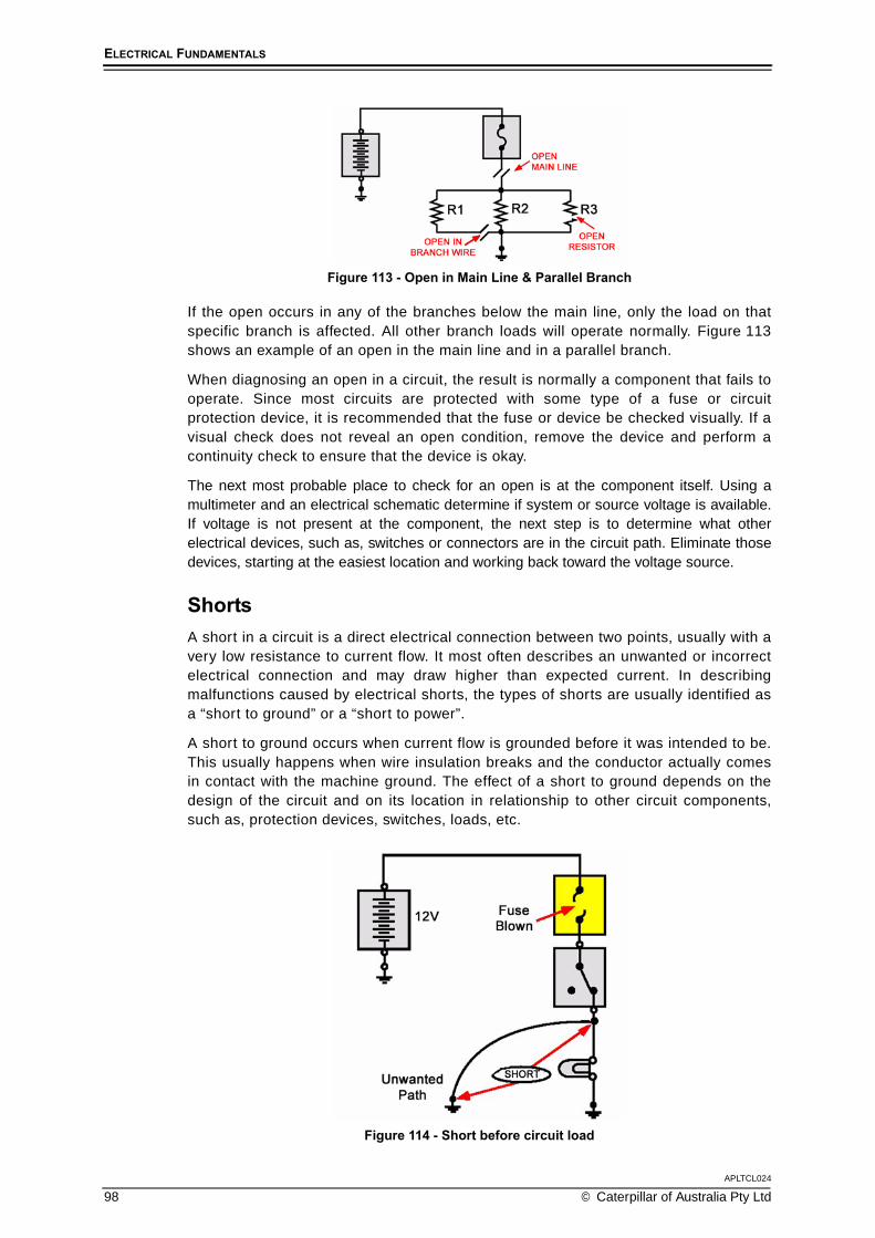
APLTCL024
98 © Caterpillar of Australia Pty Ltd
ELECTRICAL FUNDAMENTALS
Figure 113 - Open in Main Line & Parallel Branch
If the open occurs in any of the branches below the main line, only the load on thatspecific branch is affected. All other branch loads will operate normally. Figure 113shows an example of an open in the main line and in a parallel branch.
When diagnosing an open in a circuit, the result is normally a component that fails tooperate. Since most circuits are protected with some type of a fuse or circuitprotection device, it is recommended that the fuse or device be checked visually. If avisual check does not reveal an open condition, remove the device and perform acontinuity check to ensure that the device is okay.
The next most probable place to check for an open is at the component itself. Using amultimeter and an electrical schematic determine if system or source voltage is available.If voltage is not present at the component, the next step is to determine what otherelectrical devices, such as, switches or connectors are in the circuit path. Eliminate thosedevices, starting at the easiest location and working back toward the voltage source.
ShortsA short in a circuit is a direct electrical connection between two points, usually with avery low resistance to current flow. It most often describes an unwanted or incorrectelectrical connection and may draw higher than expected current. In describingmalfunctions caused by electrical shorts, the types of shorts are usually identified asa “short to ground” or a “short to power”.
A short to ground occurs when current flow is grounded before it was intended to be.This usually happens when wire insulation breaks and the conductor actually comesin contact with the machine ground. The effect of a short to ground depends on thedesign of the circuit and on its location in relationship to other circuit components,such as, protection devices, switches, loads, etc.
Figure 114 - Short before circuit load

ELECTRICAL FUNDAMENTALS
APLTCL024
© Caterpillar of Australia Pty Ltd 99
Figure 114 shows the short occurring after the protection device and switch, but before thecircuit load (lamp). In this example, a low resistance path to ground occurs whenever theswitch is turned on and source voltage is available. The result of this unwanted path willresult in a “blown” fuse (or tripped breaker) when the switch is turned on.
Figure 115 - Short before switch
Figure 115 shows the short to ground occurring before the switch. This condition isoften referred to as a “dead short”. In this situation, the fuse will “blow” any time circuitvoltage is applied.
Figure 116 - Short before controlling devices
A short to power or supply occurs when one circuit is shorted to another circuit(Figure 116). The symptoms of a short to power again depend on the location of the short.The result of this type of condition generally causes one or both circuits to operateimproperly, such as a component being energised when it is not supposed to be. Worn orfrayed electrical wiring typically causes the root cause of this condition. Also, this conditionrarely causes protection devices to “open” or damage to other components.
GroundsA grounded circuit usually results in a component failing to operate. As discussed earlier,a grounded condition indicates that the circuit has an unwanted path to the machineframe. As stated, the effect on the circuit is determined by where the ground occurs.

APLTCL024
100 © Caterpillar of Australia Pty Ltd
ELECTRICAL FUNDAMENTALS
High ResistanceCircuit malfunctions also occur when resistance levels become too high. The circuiteffect usually results in the component failing to operate or the component does notoperate according to specification. A typical cause of high resistance is a build up ofcorrosion or dirt on connections and contacts.
IntermittenceAn intermittent condition occurs when contacts or connections become loose or wheninternal component parts break. The problem usually results in lights flickering, orcomponents working intermittently. This problem usually appears as the result ofvibrations or machines moving, and is not easily diagnosed because the conditiontends to correct itself when the machine is stopped.

ELECTRICAL FUNDAMENTALS
APLTCL024
© Caterpillar of Australia Pty Ltd 101
TOPIC 7Soldering
SOLDERINGSoldering is the process of joining two metals by the use of solder alloy.
While an electrical connection might exist between two crimped wires, it may be incompleteand/or faulty. Soldering creates a solid and dependable electrical connection.
The soldering process depends upon molten solder flowing into all the surface imperfectionsof the metals to be soldered. When two pieces of metal are soldered together, a thin layer ofsolder adheres between them and completes the electrical connection.
Solder is a mixture of tin and lead and usually contains a solder flux.
Safety PrecautionsThe soldering gun or iron operates at temperatures high enough to cause seriousburns. Observe the following safety precautions:
1. Do not permit hot solder to be sprayed into the air by shaking a hot gun or iron or ahot-soldered joint.
2. Always grasp a soldering gun or iron by its insulated handle. Do not grasp thebare metal part.
3. Do not permit the metal part of a soldering gun or iron to rest or come in contact withcombustible materials. An iron should always rest on a soldering stand when not in use.
4. Don’t wear nylon or plastic clothing. Solder will burn holes in these garments.
5. The soldering iron tip needs to be very hot in order to melt solder. Contact withthe soldering tip will produce skin burns.
6. Do not inhale the fumes that are released during the soldering process; they willirritate respiratory systems.
7. If the soldering iron is electrically heated, do not use it while standing in water orengine coolant.
8. Never apply solder to a live electrical circuit.
9. Make sure that all legislative and personal safety procedures are understood andobserved when carrying out soldering tasks.

APLTCL024
102 © Caterpillar of Australia Pty Ltd
ELECTRICAL FUNDAMENTALS
PROPERTIES OF SOLDERSolder is a metal alloy, made by combining tin and lead in different proportions. Theseproportions are usually marked on the various types of solder available.
With most tin/lead solder combinations, melting does not take place all at once. Fifty-fifty solder begins to melt at 183°C (361°F), but it's not fully melted until thetemperature reaches 216°C (420°F). Between these two temperatures, the solderexists in a plastic or semi-liquid state.
The plastic range of a solder varies, depending upon the ratio of tin to lead. With 60/40solder (60% tin / 40% lead) , the range is much smaller than it is for 50/50 solder. The 63/37 ratio, known as eutectic solder has practically no plastic range, and melts almost instantlyat 183°C (361°F).
The solders most commonly used for hand soldering in electrical repair work are the60/40 type and the 63/37 type. Due to the plastic range of the 60/40 type, care needsto be taken to avoid moving any elements of the joint during the cool down period.Movement may cause what is known as a disturbed joint. A disturbed joint has arough, irregular appearance and looks dull instead of bright and shiny. A disturbedsolder joint may be unreliable and will probably require rework.
Wetting action
Figure 117 - Wetting occurs when molten solder penetrates a copper surface,forming an intermediate bond.
When the hot solder comes in contact with a copper surface, a metal solvent actiontakes place. The solder dissolves and penetrates the copper surface. The molecules ofsolder and copper blend to form a new alloy, one that's part copper and part solder. Thissolvent action is called wetting and forms the intermetallic bond between the parts(Figure 117). Wetting can only occur if the surface of the copper is free of contaminationand from the oxide film that forms when the metal is exposed to air. Solder and worksurface need to reach the proper temperature before attempting to solder.
Although the surfaces to be soldered may look clean, there is always a thin film ofoxide covering it. For a good solder bond, surface oxides must be removed during thesoldering process using flux.

ELECTRICAL FUNDAMENTALS
APLTCL024
© Caterpillar of Australia Pty Ltd 103
FluxReliable solder connections can only be accomplished with truly cleaned surfaces.Solvents can be used to clean the surfaces prior to soldering but are insufficient due tothe extremely rapid rate at which oxides form on the surface of heated metals. Toovercome this oxide film, it becomes necessary to use materials called fluxes. Fluxesconsist of natural or synthetic rosins and sometimes chemical additives called activators.
It is the function of the flux to remove oxides and keep them removed during thesoldering operation. This is accomplished by the flux action which is very corrosive atsolder melt temperatures and accounts for the flux's ability to rapidly remove metaloxides. In its unheated state, however, rosin flux is non-corrosive and non-conductiveand thus will not affect the circuitry. It is the fluxing action of removing oxides andcarrying them away, as well as preventing the reformation of new oxides that allowsthe solder to form the desired intermetallic bond.
Flux must melt at a temperature lower than solder so that it can do its job prior to thesoldering action. It will volatilize very rapidly; thus it is mandatory that flux be melted toflow onto the work surface and not be simply volatilized by the hot iron tip to providethe full benefit of the fluxing action. There are varieties of fluxes available for manypurposes and applications. The most common types include: Rosin - No Clean, Rosin- Mildly Activated and Water Soluble.
When used, liquid flux should be applied in a thin, even coat to those surfaces being joinedand prior to the application of heat. Cored wire solder and solder paste should be placed insuch a position that the flux can flow and cover the joints as the solder melts. Flux shouldbe applied so that no damage will occur to the surrounding parts and materials.
Soldering ironsSoldering irons come in a variety of sizes and shapes. A continuously tinned surfacemust be maintained on the soldering iron tip's working surface to ensure proper heattransfer and to avoid transfer of impurities to the solder connection.
Before using the soldering iron the tip should be cleaned by wiping it on a wet sponge.When not in use the iron should be kept in a holder, with its tip clean and coated witha small amount of solder.
Controlling heatControlling soldering iron tip temperature is not the key element in soldering. The keyelement is controlling the heat cycle of the work. How fast the work gets hot, how hot itgets, and how long it stays hot is the element to control for reliable solder connections.Selection of the correct sized soldering iron, and consequent tip size, is an importantfactor in controlling heat.
Thermal massThe first factor that needs to be considered when soldering is the relative thermalmass of the joint to be soldered. This mass may vary over a wide range.
Each joint has its own particular thermal mass and how this combined mass compareswith the mass of the iron tip determines the time and temperature rise of the work.

APLTCL024
104 © Caterpillar of Australia Pty Ltd
ELECTRICAL FUNDAMENTALS
Surface conditionA second factor of importance when soldering is the surface condition. If there areany oxides or other contaminants covering the pads or leads, there will be a barrier tothe flow of heat. Even though the iron tip is the right size and temperature, it may notbe able to supply enough heat to the joint to melt the solder.
Thermal linkage
Figure 118 - Minimal thermal linkage due to insufficient solder between the padand soldering iron tip
A third factor to consider is thermal linkage. This is the area of contact between theiron tip and the work.
Figure 118 shows a view of a soldering iron tip soldering a component lead. Heat istransferred through the small contact area between the soldering iron tip and pad.The thermal linkage area is small.
Figure 119 - A solder bridge provides thermal linkage to transfer heat into the padand component lead
Figure 119 also shows a view of a soldering iron tip soldering a component lead. Inthis case, the contact area is greatly increased by having a small amount of solder atthe point of contact. The tip is also in contact with both the pad and componentfurther improving the thermal linkage. This solder bridge provides thermal linkage andassures the rapid transfer of heat into the work.

ELECTRICAL FUNDAMENTALS
APLTCL024
© Caterpillar of Australia Pty Ltd 105
Applying solderIn general, the soldering iron tip should be applied to the maximum mass point of thejoint. This will permit the rapid thermal elevation of the parts to be soldered. Moltensolder always flows from the cooler area toward the hotter one.
Before solder is applied; the surface temperature of the parts being soldered must beelevated above the solder melting point. Never melt the solder against the iron tip andallow it to flow onto a surface cooler than the solder melting temperature. Solder appliedto a cleaned, fluxed and properly heated surface will melt and flow without direct contactwith the heat source and provide a smooth, even surface, filleting out to a thin edge.Improper soldering will exhibit a built-up, irregular appearance and poor filleting. For goodsolder joint strength, parts being soldered must be held in place until the solder solidifies.
If possible apply the solder to the upper portion of the joint so that the work surfaces and notthe iron will melt the solder, consequently allowing gravity to aid the solder flow. Selectingcored solder of the proper diameter will aid in controlling the amount of solder being appliedto the joint. Use a small gauge for a small joint, and a large gauge for a large joint.
Post solder cleaningWhen cleaning is required, flux residue should be removed as soon as possible, but nolater than one hour after soldering. Some fluxes may require more immediate action tofacilitate adequate removal. Mechanical means such as agitation, spraying, brushing,and other methods of applications may be used in conjunction with the cleaning solution.
The cleaning solvents, solutions and methods used should not have affected the parts,connections, and materials being cleaned. After cleaning, adequately dry the solderedarea, ensuring fingers and hands to not come into contact with hot surfaces.
Resoldering Care should be taken to avoid the need for resoldering. When resoldering is required, qualitystandards for the resoldered connection should be the same as for the original connection.
A cold or disturbed solder joint will usually require only reheating and reflowing of thesolder with the addition of suitable flux. If reheating does not correct the condition, thesolder should be removed and the joint resoldered.
Quality of Work
Figure 120 - Solder blends to the soldered surface, forming a small contact angle
Solder joints should have a smooth appearance and a satin lustre. The joints shouldbe free from scratches, sharp edges, grittiness, looseness, blistering, or otherevidence of a poor quality of work. Probe marks from test pins are acceptableproviding that they do not affect the integrity of the solder joint.

APLTCL024
106 © Caterpillar of Australia Pty Ltd
ELECTRICAL FUNDAMENTALS
An acceptable solder connection should indicate evidence of wetting and adherencewhen the solder blends to the soldered surface. The solder should form a smallcontact angle; this indicates the presence of a metallurgical bond and metalliccontinuity from solder to surface (Figure 120).
Smooth clean voids or unevenness on the surface of the solder fillet or coating areacceptable. A smooth transition from pad to component lead should be evident.
When soldering, follow these guidelines:
Use the soldering tool to heat the terminal or clip. This will transfer heat byconductance to the wires, which will become hot enough to melt the solder. Do notheat the solder directly.
Make sure that there are solder fillets between the core (conductor) and theterminal or clip, but not on the insulator If using a clip, make sure that the soldercovers the exposed conductor, and all of the clip.
If soldering around a terminal, make sure the solder covers the conductor, butdoes not extend past the conductor. It may be helpful to tilt the terminal end of thewire being repaired slightly up to prevent solder from flowing onto the terminal.
Do not apply so much solder that the individual wire strands aren’t visible.
Do not allow the soldering tool to burn the terminal or insulation.
Do not leave sharp points of solder; these can tear tape used to insulate the repair.
Do not allow individual wire strands to protrude from the repair, or to protrude overthe insulator.
Do not solder wires in a live circuit. Always disconnect power from wires and thenmake the repair.
ToolsThe following tools are recommended for use when preparing and soldering wiresor connections:
Diagonal pliers, commonly called side cutters, are used for cutting soft wire andcomponent leads. They should not be used for cutting hard metals such as, iron or steel.
Long-nose or needle-nose pliers, are used for holding wire so that the strippedend may be twisted around a terminal post, or inserted into a terminal eye.
Wire strippers are used to remove insulation from the hook-up wires. There aredifferent types of strippers, ranging from the simple type found on diagonal pliers to themore automatic multi sized strippers which can handle different wire diameters.
A soldering iron is a standard tool in the industry used for soldering wires together.There are many types of devices used for this purpose, such as soldering guns,pencil-types, etc. Soldering irons are rated by the amount of power they dissipate,and thus indirectly by the amount of heat they can develop. One hundred and onehundred twenty five Watt guns are the most popular sizes. The type of jobdetermines which size iron should be used.
Heat sinks are used to prevent overheating during soldering or unsoldering of heat-sensitive electronic parts. The heat sink is generally a clip that is attached to the leadbetween the body of the part and the terminal point at which the heat is applied. Itabsorbs heat and reduces the amount of heat conducted by the component.
Desoldering tools simplify the job of cleaning etched board solder holes of solderwhen component leads are being removed from their holes. The holes must befree of solder before the terminals of a new component may be inserted.

ELECTRICAL FUNDAMENTALS
APLTCL024
© Caterpillar of Australia Pty Ltd 107
Wire PreparationTwo or more wires that provide a conductive path for electricity must be electricallyconnected. This means that an uninsulated surface on one wire must be mechanicallyconnected to an uninsulated surface on the other wire. To ensure that the wires will notseparate, or the connection corrode, they are soldered at the junction.
Before wires may be connected and soldered, they must be properly prepared. Thisinvolves stripping away the insulation at the ends of the wire, thus providing terminal leadswhich may be connected to each other or to a terminal post or connector contact.
After removing the insulation, examine the wire for nicks or cuts and discoloration. If thewire has a shiny look and is not nicked or damage, no further preparation is needed. If thewire has a dull or dark appearance, it must be cleaned before soldering.
The final step before soldering the wire is to perform a task called “tinning”. If usingstranded wires, the wire should be twisted and placed on the tip of a heated solderingdevice and heated sufficiently so that the wire will melt the solder.
Mechanical Connections
Figure 121
Some of the more common connectors are posts, terminals and splices. Figure 121shows a connection to a terminal post. The wire should be secured to the post by athree-quarter to a full turn. Do not wind the wire around the post several times. It iswasteful and also causes problems if the connection needs to be desoldered.
Figure 122
Figure 122 shows a typical connection to a terminal strip. Twist the wire to form a hookand insert the hook into the opening on the terminal strip.

APLTCL024
108 © Caterpillar of Australia Pty Ltd
ELECTRICAL FUNDAMENTALS
Figure 123
If two wires are to be spliced, the recommended procedure is to twist each wire in the formof a hook. Combine the two hooks and apply the solder to the joint. It is recommended thatthe wires be ‘tinned’ before soldering. Figure 123 shows a hook splice connection.
Figure 124
When connecting heat sensitive components to a terminal post or terminal strip it isrecommended that a heat sink device be used. Figure 124 shows a heat sinkconnected between a silicon diode and a terminal post. The heat sink acts as a heatload and therefore reduces the heat transfer to the diode.

ELECTRICAL FUNDAMENTALS
APLTCL024
© Caterpillar of Australia Pty Ltd 109
PROCEDURE EXAMPLE
Helpful HintsGood soldering is part of a technician’s skills. Solder connections must bemechanically strong, so that they will not shake or vibrate loose causing electricalintermittence. Electrically, solder contacts must have low resistance for providingproper signal transfer. Some basic soldering rules are:
1. The soldering tip must be tinned and clean.
2. Metals to be connected must be clean.
3. Support the joint mechanically where possible.
4. Pre-tin large surfaces before soldering them together.
5. Apply the solder to the joint, not to the gun or iron tip. Solder must flow freely andhave a shiny, smooth appearance.
6. Use only enough solder to make a solid connection.
7. Where additional flux is used, apply to the joint. Only rosin flux should be used onelectrical connections.
8. Solder rapidly and do not permit components or insulation to burn or overheat.
9. Use rosin-core solder or equivalent. Do not use acid-core solder for anyelectrical connections.
Procedure Steps
1. Safety and Care
Figure 125
When using a soldering iron care must be taken to ensure personal burns do notoccur (Figure 125).

APLTCL024
110 © Caterpillar of Australia Pty Ltd
ELECTRICAL FUNDAMENTALS
The tip of the soldering iron has to be hot enough to melt metal solder...
Figure 126
... so make sure it is in a safe position and not touching anything (Figure 126).
2. Splicing: Prepare the wires to be joined
Figure 127
While the soldering iron is heating, remove an appropriate amount of the protectiveinsulation from the wires. Always use a proper stripping tool that is in good condition.
If the joint is to be sealed with a heat shrink sleeve, cut a section of this tubularmaterial long enough to overlap the cable insulation on both sides of the join. Slide itover the end of one of the wires before joining them (Figure 127).
3. Join the wires mechanically
Figure 128
Twist the wires together to make a good mechanical connection between them(Figure 128). If there are impurities in the solder, and the wires are not directlytouching each other, there may be a strong physical connection but there may not bea good electrical connection.
This is known as a ‘dry joint’. It is also very important for the surfaces to be very cleanbefore soldering or there will be a poor connection. Tinning of the individual wiresbefore soldering will assist in eliminating ‘dry joints’.

ELECTRICAL FUNDAMENTALS
APLTCL024
© Caterpillar of Australia Pty Ltd 111
4. Apply solder to splice
Figure 129
Use the soldering iron to gently heat up the wires and melt some solder.
Place the soldering iron onto the joined wires to ensure that just enough solder runssmoothly into the wires. Be careful not to use too much solder; if too much heat isapplied, the wire insulation will melt (Figure 129).
Figure 130
When soldering is finished, clean any excess flux from the joint with a rag and solvent (Figure 130).
5. Sleeve the joint
Figure 131
Once the electrical connection has been made, and it has cooled down enough placethe insulator sleeve cover over the join.
There are different types of sleeves. The most popular type is shrink wrapped onto thejoin with a heat source (Figure 131).

APLTCL024
112 © Caterpillar of Australia Pty Ltd
ELECTRICAL FUNDAMENTALS
Figure 132
Another type contains a glue which when heated melts into and seals the joint(Figure 132 left).
If there is not heat shrink sleeve available, then it is possible to seal and protect thesplice with electrical insulating tape (Figure 132 right).
6. Terminals: Check the connection length
Figure 133
To solder a wire to a terminal connector, a better connection will be obtained if thewire strands are not twisted tightly before placing through the terminal; this gives theterminal more surface area to come in contact with the wire when soldered.
However, it can be difficult to insert the wires into the terminal if they are all just loosestrands, so twist them just enough (Figure 133)...
Figure 134
... to assist in a clean insertion.
Place the bullet or terminal onto the wire (Figure 134) to check that the stripped partof the wire...

ELECTRICAL FUNDAMENTALS
APLTCL024
© Caterpillar of Australia Pty Ltd 113
Figure 135
... does not extend beyond the insulated shoulder of the terminal (Figure 135). Thenremove the wire from the terminal.
7. Apply Solder
Figure 136
Give the wires a thin preparatory coating of solder. This is called ‘tinning’ the wiresand helps to make the final connection (Figure 136).
By using resin cored solder, it is unnecessary to prepare the surfaces with a fluxmaterial because this is incorporated into the core of the solder.
Figure 137
Put the wire back in the terminal (Figure 137)...

APLTCL024
114 © Caterpillar of Australia Pty Ltd
ELECTRICAL FUNDAMENTALS
Figure 138
... and place the iron onto the terminal to get it hot enough to melt some more solderbetween the terminal and the tinned wire (Figure 138). Be careful not to use too muchsolder, and if the terminal is too hot the wire insulation will start to melt.
8. Cover the terminal
Figure 139
Once the electrical connection has been made, and it has cooled down enough toenable handling, place the insulator cover over the terminal (Figure 139)...
Figure 140
... and place the connection into service (Figure 140).