apex overview: part i opportunities and challenges … presentations/1999/apex 5-99/apex...apex...
TRANSCRIPT

APEX Overview: Part I Opportunities and Challenges in Free-
Surface Liquid Wall Research
Mohamed Abdou UCLA
APEX Meeting and Seminar Princeton Plasma Physics Laboratory
May 12-14, 1999

Liquid Walls Offer an Exciting Opportunity to HELP
Develop a New VISION for Fusion with:
1) More Attractive and Competitive Fusion Power 2) Lower Cost, Faster R&D Path

The Challenges in Free-Surface Liquid Research Present Excellent Opportunities for:
1) Greater contributions to Engineering Sciences 2) Direct coupling and outreach to other fields (e.g.
Oceanography, Metallurgy, Rocket Engines) 3) Intellectual synergism between Plasma Physicists and
Fusion Engineers.

Outline
• Limitations of Solid Walls / Traditional Concepts • APEX Objectives • Potential of Liquid Walls • Challenges of Liquid Walls • Low-Cost R&D Path • Current Research Problems

Plasma Chamber Technology
• All Components from the Edge of the Plasma to the Magnet (i.e. First Wall / Blanket / Divertor / Vacuum Vessel)
• Functions
- Provide Vacuum - Exhaust Plasma Burn Products - Power Extraction from Plasma Particles and Radiation (Surface Heat Load) - Power Extraction from Neutrons and Gamma-Rays (Bulk Heating) - Tritium Breeding - Radiation Protection

Fundamentals of Economics Show That:1. Attractive Vision Requires JOINT Physics and Technology Efforts2. Plasma Chamber Technology is Critical
Need LowFailure Rate
EnergyMultiplication
Need High Temp.Energy Extraction
Need High Power Density- High-Performance Plasma- Power Extraction Technology
t timereplacemenratefailure/1)ratefailure/1(
+
• Need Low Failure Rate:- Innovative Power Extraction Technology
• Need Short Maintenance Time:- Simple Configuration Confinement- Easier to Maintain In-Vessel Technology
thfusion MPMOiCCOE
η⋅⋅⋅++⋅=
tyAvailabili&costtreplacemen

Traditional (Evolutionary) Concepts (Solid First Wall, etc.) Have Very Limited Potential
A) Limited Performance/Economic Potential
1) Low Power Density: Neutron Wall Load ≤ 3 MW/m2 Factor of 200 Lower than LMFBR and 80 Lower than LWR
2) Low Conversion Efficiency: Exit Coolant Temperature < 400-600°C
3) Short Mean Time Between Failure: MTBF < 0.5 year
4) Long Mean Time to Recover: MTTR > 0.25 year
- Traditional Concepts: MTBF ∼ 2 MTTR - What is Needed: MTBF > 43 MTTR
B) Nuclear Environment is Dominant: Activation and Material Problems C) High Cost, Long Time for R&D
Need Revolutionary Concepts with Much Greater Potential

APEX
Objective
Identify and explore novel, possibly revolutionary, concepts for the Plasma Chamber that can: 1 - substantially improve the vision for an attractive fusion energy system; and 2 - Lower the cost and time for R&D.
Primary Criteria
1. High Power Density Capability (main driver)
Neutron Wall Load > 10 MW/m2 Surface Heat Flux > 2 MW/m2
2. High Power Conversion Efficiency ( > 40% net) 3. Low Failure Rates
MTBF > 43 MTTR 4. Faster Maintenance 5. Simpler Technological and Material Constraints

APEX APPROACH
1) Foster an Environment conducive to innovation - Encourage innovative ideas - Opportunities for talented young scientists/engineers
2) Understand and Advance the underlying Engineering Sciences 3) Utilize a multidisciplinary, multi-institution integrated TEAM to foster
collaboration, pool talents, and expand expert and specialty input. Organizations: UCLA, ANL, ORNL, SNL, LLNL, PPPL, GA, LANL, UW, UCSD, INEL
4) Provide for Open Competitive Solicitation in 1999 5) Close Coupling to the Plasma Community
- Plasma Interface Group - Joint Physics-Technology Workshops
6) Direct Participation of Material Scientists and System Design Groups 7) Direct Coupling to IFE Chamber Technology Community 8) Encourage International Collaboration
- Current participation from Germany and Japan
Two Classes of Concepts Have Emerged From APEX as Very Promising
1. Liquid Walls (Revolutionary)
• High Power Density, “true” low activation, reduce material problems, lower failure rate, easier maintenance
• Candidate liquids: Li, Sn-Li, Flibe
• Design Options: - CLIFF - Gravity-Momentum-Driven (with and without rotation) - Electromagnetically Restrained (Lithium Only)
2. High-Temperature Refractory Alloy (Evolutionary)
• High-Temperature, High-Power Density Capability
• Candidate Structure: W alloys (Nb, T-111, TZM)
• Design Options: - Helium Cooling (high pressure) - EVOLVE (Two-Phase Lithium Flow)

APEX Results Show Great Potential for an ALL-LIQUID FW/Blanket
Fast Flow FW
Thick LiquidBlanket
Vacuum Vessel
q High Power Density (PNW up to 30MW/m2)
q High Thermal Conversion Efficiency (> 40%) q Dramatic Reduction in Radiation Damage and Activation
q Higher Availability − Lower Failure Rates − Faster Maintenance
* Temperatures shown in figure are for Flibe

Liquid Walls Dramatically Increase Lifetime of Structure
Conclusions • An Order of Magnitude reduction in He for:
• Flibe: 20 cm • Lithium: 45 cm • For sufficiently thick liquid: Lifetime can be greater than plant
lifetime
1
10
100
1000
104
-10 0 10 20 30 40 50
LiFlibeSn-LiLi-Pb
Liquid Layer Thickness, cm
Wall Load =10MW/m2
Helium Production
Li, Flibe, and Li-Pb:nat.Li-6Sn-Li:90%Li-6
1
10
100
1000
-10 0 10 20 30 40 50
LiFlibeSn-LiLi-Pb
Liquid Layer Thickness, cm
Wall Load =10MW/m2
DPA
Li, Flibe, and Li-Pb:nat.Li-6Sn-Li:90%Li-6

Liquid Walls Provide a Good Low Activation Solution by Reducing Both Hazard and Volume in First Wall/ Blanket
What 40 cm of Flibe in front of structure can do Activation Hazard • Lower by two orders of magnitude
(reduction in flux; soften the spectrum) Activation Volume • Accumulated Radwaste Volume Lower by THREE orders of magnitude
- High Wall Load capability (a factor of 10) - Volume of the structure is a factor of 20 lower
(area • thickness) - Replacement due to FW end of life is less by a factor of ten (100 x 1/10) - Replacement due to “unscheduled” FAILURES is lower by at least a factor of
10
Low Level Waste (Shield, magnets, etc.) • Will be lower because of smaller size (high power density)
1
10
100
1000
104
105
Hazard Volume
With Liquid WallWithout Liquid

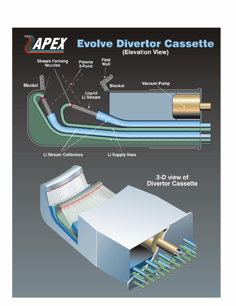
Liquid Concepts Being Explored 1.Liquid First Wall (CLIFF)
- 1 cm liquid removes all the surface heat - Near-Term Applications in Plasma Devices
2.Thick Liquid FW/Blanket
- Highest Potential but Most Challenging A. Electromagnetically-Restrained Thick Lithium B. Contiguous Gravity-Momentum-Rotational Flow C. Separate Liquid FW and Liquid Blanket
Candidate Liquids
- Lithium - Sn-Li - Flibe

Challenging Issues for Liquid Walls
1. Plasma-Wall Interaction
A. Surface Interactions - What is the Allowable Temperature of the Liquid Surface Facing the
Plasma?
B. “Bulk” Interactions - Requirements on Field Penetration, Field Error, etc. - Plasma Disruptions
2. Temperature Control
- How to Achieve Low Surface Temperature and High Bulk Temperature? 3. Hydrodynamic Configuration
- How to Form and Maintain the liquid FW/Blanket?

Hydrodynamic Configuration Can Liquid Walls be Formed and Maintained?
Ultimate Vision
SMART LIQUIDS For Now: 1) EM Restrained 2) Gravity-Momentum Driven With Some Ingenuity from Young Researchers:
- The answer is YES
- Confirmed by Solving 3-D Navier Stokes Equations
- Optimum Flow Configurations are somewhat different for magnetic confinement concepts (FRC, ST, Advanced Tokamaks, etc.)
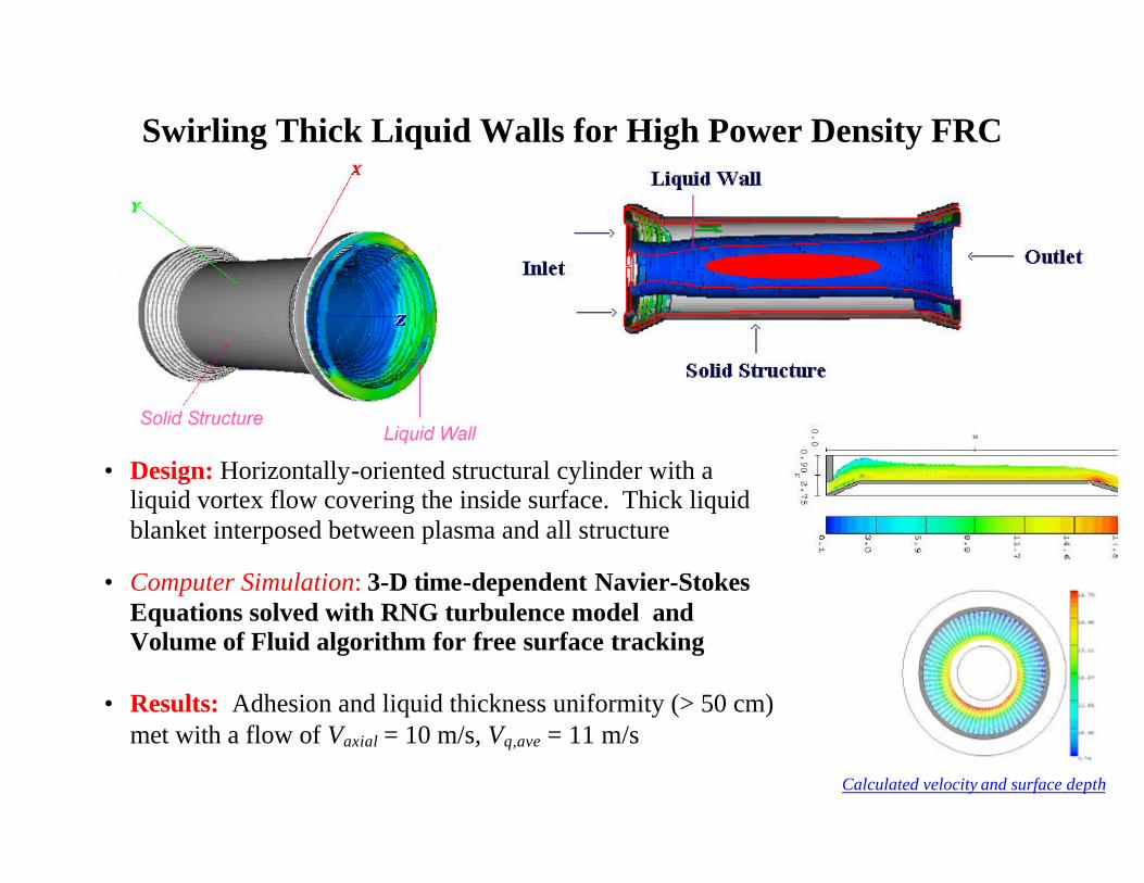
Swirling Thick Liquid Walls for High Power Density FRC
• Design: Horizontally-oriented structural cylinder with a liquid vortex flow covering the inside surface. Thick liquid blanket interposed between plasma and all structure
• Computer Simulation: 3-D time-dependent Navier-Stokes Equations solved with RNG turbulence model and Volume of Fluid algorithm for free surface tracking
• Results: Adhesion and liquid thickness uniformity (> 50 cm)
met with a flow of Vaxial = 10 m/s, Vθ,ave = 11 m/s
Calculated velocity and surface depth

Toroidally Rotating Thick Liquid Wall for the ST
Design Concept:
• Thick liquid flow from reactor top
• Outboard: Fluid remains attached to outer wall due to centrifugal acceleration from the toroidal liquid velocity
• Inboard: Fast annular liquid jet
Simulation Results:
• Step in outboard vacuum vessel topology helps maintain liquid thickness > 30 cm
• Calculated outboard inlet velocity, Vpoloidal = 4.5 m/s, Vtoroidal,ave = 12 m/s
• Inboard jet Vz = 15 m/s is high to prevent excessive thinning, < 30%

Advanced Tokamak
3-D Hydrodynamics Calculation Indicates that a Stable Thick Flibe-Liquid Wall can be Established in an Advanced Tokamak Configuration
Inlet velocity = 15 m/s; Initial outboard and inboard thickness = 50 cm
Outboard thick flowing liquid wall Inboard thick flowing
liquid wall
ARIES-RS Geometric Configuration (major radius 5.52 m)
The thick liquid layer:
♦ is injected at the top of the reactor chamber with an angle tangential to the structural wall
♦ adheres to structural wall by means of centrifugal and inertial forces
Area expansion Toroidal width = 61 cm Corresponding to 10o sector

Some amount of thinning was observed along the poloidal path due to gravitational thinning and toroidal area expansion
z-velocity components along the structural inner walls from 3-D hydrodynamics calculations
Inlet velocity =15 m/s
t/pass = 0.5 second
Velocity increases by 33%
Initial thickness = 50 cm Inlet velocity = 8 m/s
t/pass = 0.9 second
Velocity increases 2 times
Can be corrected by changing the injection angle

Optimum Hydrodynamic Configurations for ST and Advanced Tokamaks can be Different
ST: Poloidal Flow with TOROIDAL ROTATION Typical Vv = 5 m/s V? = 11 m/s
AT: Poloidal Flow (No Rotation) Reason
To Adhere to the wall: U2/R > g - ST is taller and has Higher Radius of Curvature (R) in the poloidal direction
RST ~ 2 RAT [U2/R]AT ~ 2[U2/R]ST
- But, ST has smaller radius of curvature in toroidal direction than in the poloidal direction - Therefore, Toroidal Rotation of Flow in ST results in substantial increment in the centripetal
acceleration towards the backwall and better adherence to backwall - Also, since ST is taller, the increase in velocity due to gravitation acceleration (and thinning) is
larger

Plasma-Liquid Surface Interaction and Temperature Control (Conflicting Requirements on Temperature and Velocity)
1. Plasma-Wall Interaction
Tmax
S < Tps (Plasma allowable) T p
s Uncertain
2. High Thermal Efficiency
Tout
b > Teb (for efficiency)
3. Newton’s Law of Cooling
Ts – Tb = q/h Free Surface h Uncertain
4. Adheres to Wall
V2/R g> 5. Overcome Thinning
•
m = ρVA V(t) = Vo + Vg(t) Vo >> Vg(t)
6. Higher V increases pumping power, reduces temp. rise
∆P ~ ρV2 Toutb – Tin
b = (Q + q) /•
m Cp
Tin
b
Tout
b
Tmax
S
Tb
Liquid Plasma
Ts
q Q

What is the Maximum Allowable Surface Temperature?
• An Edge Modelling Group for ALPS/APEX has been formed that involves a
number of experts from the Physics community
- J. Brooks, Coordinator - T. Rognlien responsible specifically for liquid walls (APEX)
• Reliable Answer requires:
- extensive modelling - plasma experiments with liquid surfaces
• Current “Best Guess” on Ts from plasma impurity limit: Lithium: Ts ~ 490ºC Flibe: Ts ~ 560ºC Sn-Li: Ts ~ 820ºC (low vapor pressure)
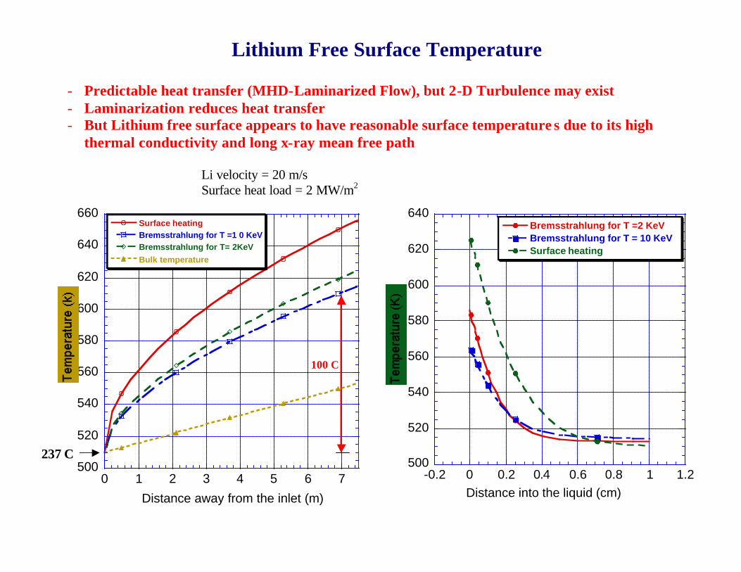
Lithium Free Surface Temperature
- Predictable heat transfer (MHD-Laminarized Flow), but 2-D Turbulence may exist - Laminarization reduces heat transfer - But Lithium free surface appears to have reasonable surface temperature s due to its high
thermal conductivity and long x-ray mean free path
Li velocity = 20 m/s Surface heat load = 2 MW/m2
100 C
500
520
540
560
580
600
620
640
-0.2 0 0.2 0.4 0.6 0.8 1 1.2
Bremsstrahlung for T =2 KeVBremsstrahlung for T = 10 KeVSurface heating
Distance into the liquid (cm)
500
520
540
560
580
600
620
640
660
0 1 2 3 4 5 6 7
Surface heatingBremsstrahlung for T =1 0 KeVBremsstrahlung for T= 2KeVBulk temperature
Distance away from the inlet (m)
237 C

Effect of Different Heat Transfer Mechanisms on Flibe Free Surface Temperature
q If the Flibe flow is laminarized, the Flibe free surface can be overly heated. The film temperature drop can reach 700 oC at the bottom of ARIES-RS under APEX 2 MW/m2 surface heat load (curve 1).
q Turbulent heat transfer considerably reduces
Flibe free-surface temperature drop (curve 2). q Accounting for Bremsstrahlung radiation
penetration further reduces surface temperature by about 90 oC (curve 3).
q Heat transfer at the vacuum/free surface
interface can be significantly enhanced by the existence of surface turbulence (Smolentsev, curve 4)
q Initial calculation based on k-e model indicates
that turbulence suppression due to MHD can be neglected at the current parameters of interest (Smolentsev, curve 4)
-100
0
100
200
300
400
500
600
700
0 1 2 3 4 5 6 7 8
Laminar flow (without accounting x-ray penetration)
MHD effect and existence of surface turbulence Accounting xray penetration for turbulent film Turbulentn film (without accounting x-ray penetration)
Distance away from the inlet (m)
1
2
34

Impact of Temperature Control on
Hydrodynamic Configuration • Thermal Efficiency Depends on Outlet Temperature
To attain ? (net) > 40% need Tout > 600ºC Lithium
- The maximum allowable surface temperature is probably < 500ºC - Therefore two coolant streams are necessary
Flibe - Allowable surface temperature probably in the range 550 to 650ºC - For > 650ºC: One Coolant Stream Possible - For < 550ºC: Two Coolant Streams Needed
Two Coolant Streams - Fast moving thin liquid jet as low-temperature FW - Slow moving thick liquid as high-temperature blanket - Several Design Options Exist for Hydrodynamic Configurations

Several Innovative schemes have been proposed in
APEX to ensure compatibility of free-surface liquids with plasma operation while attaining High Thermal Efficiency
These include
Design innovation:
1. Fast flowing liquid jet, separate from slow moving liquid blanket, to keep surface temperature of the liquid (and hence evaporation rate) low, while the slow moving blanket has high outlet temperature
2. New Schemes to promote controlled surface mixing and wave formation to eliminate surface thermal boundary layer
Material innovation: discovery of a new lithium-containing material (SnLi) that has low vapor pressure at elevated temperatures
Accounting for hard Bremsstrahlung radiation penetration: the surface heat load can be deposited deeper in the liquid; this significantly reduces the liquid jet surface temperature

APEX Modeling of Free-Surface Flow is A Challenging Engineering
Science Problem and is Attracting Outstanding International Experts (UCLA/Toyama/Tokai University Collaboration- Professors Satake and Kunugi)
Reynolds number ~ 5000
Free Surface
Wall Boundary
APEX Engineering Science

Challenge: How to Accommodate Void Penetrations (For Heating, Fueling, etc.) in Liquid Walls?
APEX Approach to Problems
1. Understand the Problem and the Underlying Sciences 2. Search for “Innovative Solutions”
Our Job is “How to Make Things Work”
3. Do good Analysis using the best engineering sciences tool available 4. Confirm by “low-cost and fast” experiments
Penetration Analysis
- Calculations were performed for Elliptical Penetrations solving 3-D, time-dependent Navier-Stokes equations using the best computational tools
- Results are Very Interesting and Encouraging. Solutions are being developed
to overcome problems revealed by the calculations


Convective Liquid Flow First Wall (CLIFF) Concepts
• Underlying structure protected by a fast moving layer of liquid, typically 1 to 2 cm thick at 10 to 20 m/s.
• Liquid adheres to structural walls by means of centrifugal force • 2D hydrodynamic calculations confirm near equilibrium flow for
Flibe at 2 cm depth and 10 m/s velocity (below)
Film Former(Liquid Lithium Manifold)
Fast Flowing Lithium FilmCoats Inner Blanket Surface
Lithium DropletsCollect in Reservoir
and Recirculate
Blanket Module(Slow Moving Lithium)
Convective Liquid layer Design
0.5
1
1.5
2
2.5
0 0.5 1 1.5 2 2.5 3
Hydraulic approximation, ff=0.017Flow3D with RNG turbulence model
Flow Distance from Nozzle (m)
2D Analysis of FW Flibe flow

The Thin Liquid Wall Concept (CLIFF)
Has Near Term Applications Advantages
• Removal of surface heat loads (greater than 2 MW/m2 possible). Local peaking and transients can be tolerated.
• FW surface protected from sputtering erosion and possibly disruption damage • Elimination of high thermal stresses and pressures in solid FW components, having a
potentially positive impact of FW/Blanket failure rates • Possible reduction of structure-to-breeder material ratio in FW area, with breeder
material facing virgin neutron flux • Integrated divertor surface possible where CLiFF removes all α heat • Complex tokamak D-shape and port penetration can be accommodated,
implementation is straight-forward
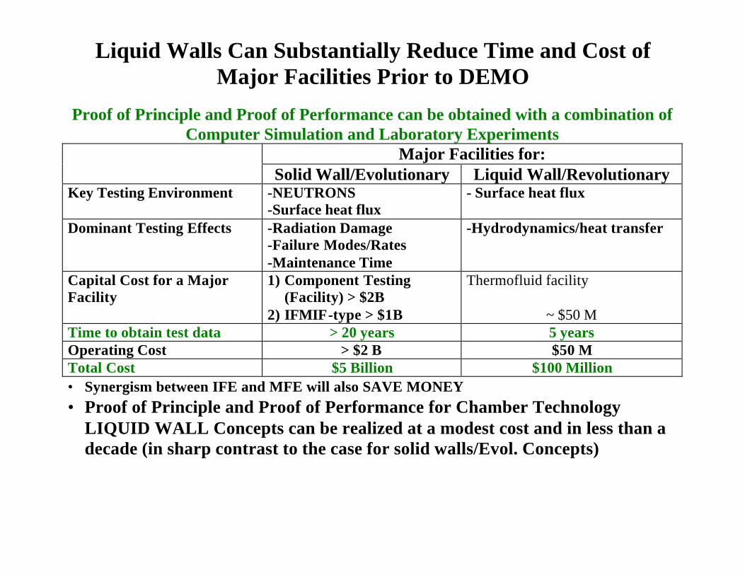
Liquid Walls Can Substantially Reduce Time and Cost of Major Facilities Prior to DEMO
Proof of Principle and Proof of Performance can be obtained with a combination of
Computer Simulation and Laboratory Experiments Major Facilities for:
Solid Wall/Evolutionary Liquid Wall/Revolutionary Key Testing Environment -NEUTRONS
-Surface heat flux - Surface heat flux
Dominant Testing Effects -Radiation Damage -Failure Modes/Rates -Maintenance Time
-Hydrodynamics/heat transfer
Capital Cost for a Major Facility
1) Component Testing (Facility) > $2B
2) IFMIF-type > $1B
Thermofluid facility
~ $50 M Time to obtain test data > 20 years 5 years Operating Cost > $2 B $50 M Total Cost $5 Billion $100 Million • Synergism between IFE and MFE will also SAVE MONEY • Proof of Principle and Proof of Performance for Chamber Technology
LIQUID WALL Concepts can be realized at a modest cost and in less than a decade (in sharp contrast to the case for solid walls/Evol. Concepts)

Liquid Wall in NSTX Provides Exciting Opportunities
CLiFF
q It helps NSTX remove high heat flux q It provides excellent data on plasma liquid
interactions