aoc webinar online training sessions
TRANSCRIPT

Day – 1 Theory of FEM
AEI EDU SUPPORT, 22ND DEC 2016
Altair HyperWorks Edu Training & Support
AOC Webinar Online Training Sessions
[email protected] www.altairhyperworks.in/aoc

© 2016 Altair Engineering, Inc. Proprietary and Confidential. All rights reserved.
Credits & Acknowledgements for this Theory session
All the Contents provided in this presentation have been
sourced with due permission from
“Practical Finite Element Analysis”Author - Nitin Gokhale.
Thank You Nitin Gokhale for your help and permission
For ordering a copy of this book kindly visit -
http://finitetoinfinite.com/Buyonline.html

© 2016 Altair Engineering, Inc. Proprietary and Confidential. All rights reserved.
Altair India & Edu support Activity
Altair’s corporate culture thrives on seeking out business and technology firsts to radically
change the way organizations design products and make decisions.
Founded in 1985, Altair is focused on the development and application of simulation technology
to synthesize and optimize designs, processes and decisions for improved business
performance. Privately held with more than 2,600 employees, Altair is headquartered in Troy,
Michigan, USA with more than 45 offices throughout 20 countries, and serves more than 5,000
corporate clients across broad industry segments.
Founded in 1985
2,600+ employees
45+ offices
5,000 corporate clients
Troy, Michigan, USA
James Scapa
Troy, Michigan, USA

© 2016 Altair Engineering, Inc. Proprietary and Confidential. All rights reserved.
Altair India & Edu support Activity
Altair India Education Team supports Students/Faculties of engineering colleges all over india
The objective of
the FREE contest
is to offer
students &
young faculty
technical training
& certification on
HyperWorks
Student Edition
for a combination
of industry defined
problem
Altair India provides sponsorship for
Teams who participate in
Baja/Supra/FSAE/Solar
via
• Full version license of Altair
HyperWorks to Training on use of
CAE/CFD/MBD for validation &
optimisation of design/FEA
and
• Technical support on use of
HyperWorks for their design/FEA
technical queries
Altair India provides
sponsorship for
UG/PG/ Ph.D student
projects via
• Full version license
of Altair
HyperWorks and
• Technical training &
support on use of
HyperWorks for
their design/FEA
technical queries
AOC India Baja/Supra/FSAE/Solar Student Projects

© 2016 Altair Engineering, Inc. Proprietary and Confidential. All rights reserved.
Altair HyperWorks Module
Altair HyperWorks Student edition include various Pre/Post Processor and Solver
HyperMesh is worlds
leading high-
performance Finite
element pre
processor
HyperGraph is Highly
advanced post
processor where you
can generate graph
from your results
HyperView is
complete post
processing
environment for
FEA/MBD/CFD

© 2016 Altair Engineering, Inc. Proprietary and Confidential. All rights reserved.
Altair HyperWorks Module
Altair HyperWorks Student edition include various Pre/Post Processor and Solver
Altair Optistruct is
modern structural
analysis solver for
linear non linear
problem under static
& dynamic loading
Altair Radioss is
leading structural
analysis solver for
highly non-linear
problem under
dynamic loading
MotionSolve is altair’s
integrated solution which
provide complete solution
for mechanical system
simulation and multi body
dynamics
AcuSolve is general
purpose computational
fluid dynamics solver
that is capable of solving
most demanding
industrial & scientific
application

© 2016 Altair Engineering, Inc. Proprietary and Confidential. All rights reserved.
EDU Support Forum, certification & e-book downloads
Altair Edu Support forum where you
can ask and view your technical
queries
Altair University provides you free E-Books
© 2016 Altair Engineering, Inc. Proprietary and Confidential. All rights reserved.
India EDU Support Team Contacts
• Pune#701-707, City Towers,
Dhole Patil Road,
Pune 411 001
• Bangalore Mercury 2B Block, 5th Floor,
Prestige Tech Park Sarjapur Marathahalli
Outer Ring Road Bangalore
Offices Also in Delhi, Hyderabad & Chennai
Website - www.altairhyperworks.in/aoc
Email ID – [email protected]

© 2016 Altair Engineering, Inc. Proprietary and Confidential. All rights reserved.

© 2016 Altair Engineering, Inc. Proprietary and Confidential. All rights reserved.
Who
Can
Participate
Who all Can Participate in the Contest ???
AOC Contest is for students & Faculty (UG / PG / Ph.D.) of Mechanical, Automobile, Aerospace, Civil
& Production Engineering.

© 2016 Altair Engineering, Inc. Proprietary and Confidential. All rights reserved.
AOC Webinar Series Agenda
Sr NO Date Day Time Topic
1 22nd Dec, 2016 Thursday ( 2 – 5 ) PM Theory of FEM
2 23rd Dec, 2016 Friday ( 2 – 5 ) PM 1D Analysis
3 24th Dec, 2016 Saturday ( 2 – 5 ) PM 2D Analysis
4 26th Dec, 2016 Monday ( 2 – 5 ) PM 3D Analysis
5 27th Dec, 2016 Tuesday ( 2 – 5 ) PM Linear Analysis
6 28th Dec, 2016 Wednesday ( 2 – 5 ) PM Topology Optimization
7 29th Dec, 2016 Thursday ( 2 – 5 ) PM Topography Optimization
8 30th Dec, 2016 Friday ( 2 – 5 ) PM Size Optimization
9 31st Dec, 2016 Saturday ( 2 – 5 ) PM Shape Optimization

© 2016 Altair Engineering, Inc. Proprietary and Confidential. All rights reserved.
Sr No Date Day Time Topic
10 2nd Jan, 2017 Monday ( 2 – 5 ) PM Introduction to CFD
11 3rd Jan, 2017 Tuesday ( 2 – 5 ) PM AcuSolve Hands-on
12 4th Jan, 2017 Wednesday ( 2 – 5 ) PM Introduction to MBD
13 5nth Jan, 2017 Thursday ( 2 – 5 ) PM Motion Solve / Motion view Hands -on
14 9th Jan, 2017 Monday ( 2 – 5 ) PM Introduction to Radioss
15 10th Jan, 2017 Tuesday ( 2 – 5 ) PM Radioss Hands-on Part 1
16 11th Jan, 2017 Wednesday ( 2 – 5 ) PM Radioss Hands-on Part 2
AOC Webinar Series Agenda

© 2016 Altair Engineering, Inc. Proprietary and Confidential. All rights reserved.
Today’s Agenda
• Introduction to Meshing
• Why do we carry out Meshing
• Types of Elements
• How to decide the ElementType
• Can we solve the same problem using 1-D, 2-D, and 3-D elements
• How to decide element length
• How to start meshing
• Meshing in critical areas
• 1-D Meshing
• When to use 1-D elements
• Types of 1-D Elements
• 2-D Meshing
• When to use 2-D elements
• Family of 2-D elements
• How not to mesh

© 2016 Altair Engineering, Inc. Proprietary and Confidential. All rights reserved.Copyright © 2012 Altair Engineering, Inc. Proprietary and Confidential. All rights reserved.
• 3-D Meshing
• When to use 3-D elements
• DOFs for solid elements
• How not to mesh
• Element Quality and Checks
• General element quality checks
• 2-D Quality checks
• Other checks for 2-D meshing
• Quality checks for tetra meshing
• Other checks for tetrameshing
• Brick mesh quality checks
• Other checks for brick meshing
• Material and Property Information
• Material Classification
• Material Properties
Today’s Agenda

© 2016 Altair Engineering, Inc. Proprietary and Confidential. All rights reserved.
Introduction to Meshing
Why do we carry out Meshing?
The basic idea of FEA is to make calculations at only limited (Finite) number of points and then interpolate the results for the entire domain (surface or volume). Any continuous object has infinite degrees of freedom and it’s just not possible to solve the problem in this format. Finite Element Method reduces the degrees of freedom from infinite to finite with the help of discretization or meshing (nodes and elements).
Types of Elements :-

© 2016 Altair Engineering, Inc. Proprietary and Confidential. All rights reserved.Introduction to Meshing
How to Decide the Element Type
a. Geometry size and shape
For an analysis, the software needs all three dimensions defined. It can not make calculations unless the geometry is definedcompletely (by meshing using nodes and elements).
The geometry can be categorized as 1-D, 2-D, or 3-D based on the dominant dimensions and then they type of element is
selected accordingly.
1-D element: Used for geometries having one of the dimensions that is very large in comparison to the other two.
The shape of the 1-D element is a line. When the element is created by connecting two nodes, the software knows about only one out of the 3 dimensions. The remaining two dimensions, the area of the cross section, must be defined by the user as additional input data and assigned to the respective elements
Practical Example: Long shaft, rod, beam, column, spot welding, bolted joints, pin joints, bearing modeling, etc.

© 2016 Altair Engineering, Inc. Proprietary and Confidential. All rights reserved.
Introduction to Meshing2-D Element: Used when two of the dimensions are very large in comparison to the third one. 2-D meshing is carried out on a
mid surface of the part. 2-D elements are planar, just like paper. By creating 2-D elements, the software knows 2 out of the 3
required dimensions. The third dimension, thickness, has to provided by the user as an additional input data.
Why is 2-D meshing carried out on a mid surface?Mathematically, the element thickness specified by the user is
assigned half on the element top and half on the bottom side.
Hence, in order to represent the geometry appropriately, it is
necessary to extract the mid surface and then mesh on the mid
surface.
Practical Examples: All sheet metal parts, plastic components
like instrument panels, etc. In general, 2-D meshing is used for
parts having a width / thickness ratio > 20.
Limitations of mid surface and 2-D meshing –2-D meshing would lead to a higher approximation if used for
- variable part thickness
- surfaces are not planner and have different features on two sides.
© 2016 Altair Engineering, Inc. Proprietary and Confidential. All rights reserved.
Introduction to Meshing
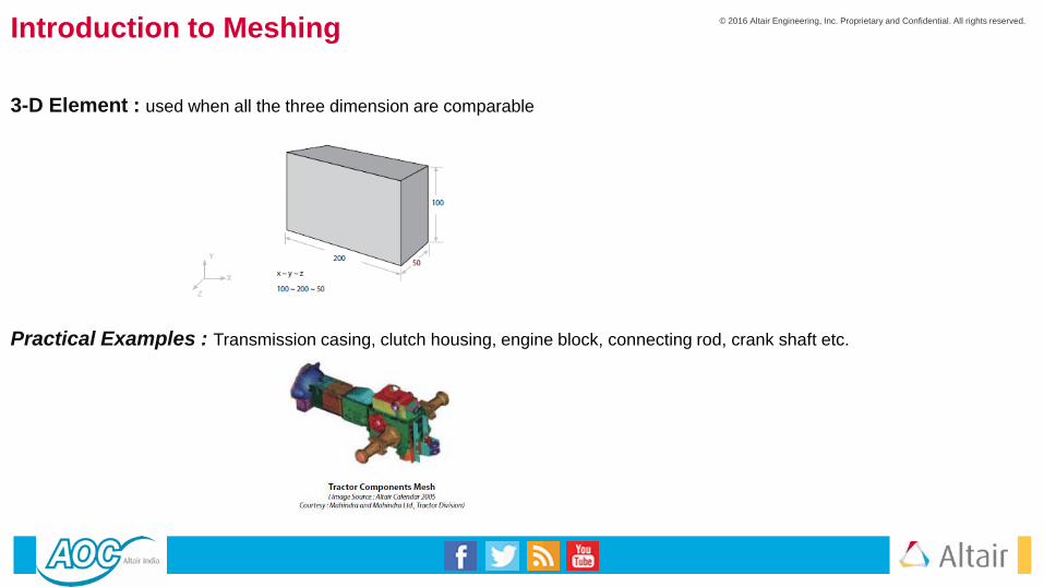
3-D Element : used when all the three dimension are comparable
Practical Examples : Transmission casing, clutch housing, engine block, connecting rod, crank shaft etc.

© 2016 Altair Engineering, Inc. Proprietary and Confidential. All rights reserved.
Introduction to Meshing
b. Based on the type of analysis :Structural and fatigue analysis - Quad, hex elements are preferred over trias, tetras and pentas.
Crash and Non-linear analysis – Priority to mesh flow lines and brick elements over tetrahedron.
Mold flow analysis – Triangular element are preferred over quadrilateral.
Dynamic analysis – When the geometry is borderline between the classification of 2-D and 3-D
geometry, 2-D shell elements are preferred over 3-D. This is because shell elements being
less stiffer captures the mode shapes accurately and with a fewer number of nodes and
elements.
c. Time allotted for project :When time is not a constraint, the appropriate selection of elements, mesh flow lines, and a good
mesh quality is recommended. Sometimes due to a very tight deadline, the analyst is forced to submit
the report quickly. For such situations
1) Automatic or batch meshing tools could be used instead of time consuming but structured
and good quality providing methods.
2) For 3-D meshing tetras are preferred over hexas.
3) If the assembly of several components is involved then only the critical parts are meshed
appropriately. Other parts are either coarse meshed or represented approximately by
1-D beams, springs, concentrated mass, etc.
© 2016 Altair Engineering, Inc. Proprietary and Confidential. All rights reserved.
Introduction to Meshing
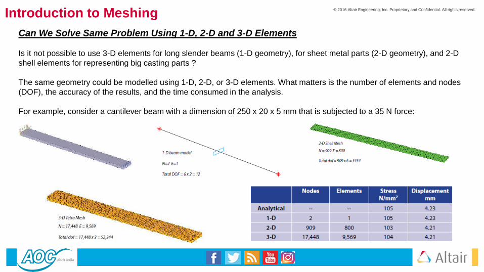
Can We Solve Same Problem Using 1-D, 2-D and 3-D Elements
Is it not possible to use 3-D elements for long slender beams (1-D geometry), for sheet metal parts (2-D geometry), and 2-D
shell elements for representing big casting parts ?
The same geometry could be modelled using 1-D, 2-D, or 3-D elements. What matters is the number of elements and nodes
(DOF), the accuracy of the results, and the time consumed in the analysis.
For example, consider a cantilever beam with a dimension of 250 x 20 x 5 mm that is subjected to a 35 N force:
© 2016 Altair Engineering, Inc. Proprietary and Confidential. All rights reserved.
Introduction to Meshing
How to Decide Element Length
1) Based on previous experience with a similar type of problem (successful correlation with experimental results).
2) Type of analysis: Linear static analysis could be easily carried out quickly with a large number of nodes and
elements, but crash, non-linear, CFD, or dynamic analysis takes a lot of time. Keeping control on the number of
nodes and elements is necessary.
3) Hardware configuration and graphics card capacity of the available computer. An experienced CAE Engineer
knows the limit of the nodes that can be satisfactorily handled with the given hardware configuration.
Suppose you are a part of a newly formed CAE group (no clear guidelines are available, and there is no
experienced person in the group) : In the first run, accept the default element length. Mesh with the
basic rules. Then run the analysis and observe the high stress regions. Remesh the localized areas of high stress (with smaller
element length) and solve again. Compare the difference in the original and the new results. Continue the process until
convergence is achieved (5 to 10% difference in strain energy / maximum stress value).
© 2016 Altair Engineering, Inc. Proprietary and Confidential. All rights reserved.
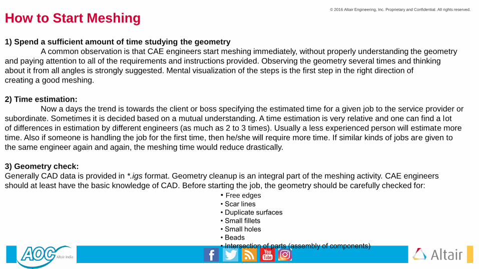
How to Start Meshing
1) Spend a sufficient amount of time studying the geometry
A common observation is that CAE engineers start meshing immediately, without properly understanding the geometry
and paying attention to all of the requirements and instructions provided. Observing the geometry several times and thinking
about it from all angles is strongly suggested. Mental visualization of the steps is the first step in the right direction of
creating a good meshing.
2) Time estimation:
Now a days the trend is towards the client or boss specifying the estimated time for a given job to the service provider or
subordinate. Sometimes it is decided based on a mutual understanding. A time estimation is very relative and one can find a lot
of differences in estimation by different engineers (as much as 2 to 3 times). Usually a less experienced person will estimate more
time. Also if someone is handling the job for the first time, then he/she will require more time. If similar kinds of jobs are given to
the same engineer again and again, the meshing time would reduce drastically.
3) Geometry check:
Generally CAD data is provided in *.igs format. Geometry cleanup is an integral part of the meshing activity. CAE engineers
should at least have the basic knowledge of CAD. Before starting the job, the geometry should be carefully checked for:
• Free edges
• Scar lines
• Duplicate surfaces
• Small fillets
• Small holes
• Beads
• Intersection of parts (assembly of components)

© 2016 Altair Engineering, Inc. Proprietary and Confidential. All rights reserved.
Introduction to Meshing
If suppressing fillets, small holes, beads, or the generation of a mid surface is required for meshing, then why isn’t the
CAD data provided in the way needed for CAE by the CAD engineers?
Yes, theoretically that would be an ideal situation, but practically everyone works with a very tight schedule and target
dates. CAD data is generated keeping in mind the final drawing to be released for manufacturing. The same CAD model is provided
simultaneously to the tools and jig /fixture manufactures, vendors, purchase engineers, and CAE engineers, etc.
The simplification required for a FEA is understood better by a CAE engineer than a CAD engineer. HyperWorks software's
provides special tools for geometry cleanup and simplification, which are usually much faster than CAD software. Many times, for
complicated geometry, surfacing operations fail in CAD software and it could be easily handled by the CAE engineer by avoiding the
geometry and generating the mesh using manual or special meshing operations.
4) Symmetry check :
Complete part symmetry
Meshing only a quarter of the plate and reflecting it
twice is advisable.
Sub part symmetry , repetition of features, and
the copy/paste command Meshing the highlighted
22.5o portion and then using reflection and rotation
would lead to a faster mesh as well as the same structure of elements and
nodes around the critical areas (holes).

© 2016 Altair Engineering, Inc. Proprietary and Confidential. All rights reserved.
Introduction to Meshing
5 ) Selection of type of elements:
In real life, we rarely use only one type of element. It is usually a combination of different types of elements (1-D, 2-D,
3-D, and others).
In the below figure, the handle of the bucket is modeled by beam (1-D) elements, the bucket body uses shell (2-D)
elements, and the connection between the handle and the bucket body through RBE2 (rigid) elements.
6) Type of meshing :
i. Geometry based – The mesh is associated to the geometry. If the geometry is modified, the mesh will also get
updated accordingly (automatically). The boundary conditions could be applied on the geometry like a surface or edge, etc.
ii. FE based – Mesh is non associative. The boundary conditions are applied on the elements and nodes only.
© 2016 Altair Engineering, Inc. Proprietary and Confidential. All rights reserved.
Introduction to Meshing
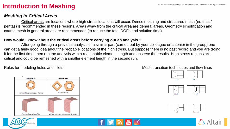
Meshing in Critical Areas
Critical areas are locations where high stress locations will occur. Dense meshing and structured mesh (no trias /
pentas) is recommended in these regions. Areas away from the critical area are general areas. Geometry simplification and
coarse mesh in general areas are recommended (to reduce the total DOFs and solution time).
How would I know about the critical areas before carrying out an analysis ?
After going through a previous analysis of a similar part (carried out by your colleague or a senior in the group) one
can get a fairly good idea about the probable locations of the high stress. But suppose there is no past record and you are doing
it for the first time, then run the analysis with a reasonable element length and observe the results. High stress regions are
critical and could be remeshed with a smaller element length in the second run.
Rules for modeling holes and fillets: Mesh transition techniques and flow lines
© 2016 Altair Engineering, Inc. Proprietary and Confidential. All rights reserved.
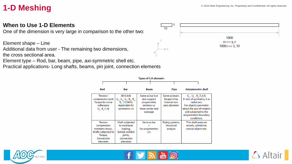
1-D Meshing
When to Use 1-D ElementsOne of the dimension is very large in comparison to the other two:
Element shape – Line
Additional data from user - The remaining two dimensions,
the cross sectional area.
Element type – Rod, bar, beam, pipe, axi-symmetric shell etc.
Practical applications- Long shafts, beams, pin joint, connection elements

© 2016 Altair Engineering, Inc. Proprietary and Confidential. All rights reserved.
2-D MeshingWhen to Use 2-D Elements2-D elements are used when two of the dimensions are very large in comparison to the third dimension.
Element shape : Quad, tria
Additional data from user : Remaining dimension i.e. thickness
Element type : Thin shell, plate, membrane, plane stress, plane strain, axi-symmetric solid etc.
Practical applications : Sheet metal parts, plastic components like instrument panel etc.
Why is 2-D meshing is carried out on the mid surface?Quite often the geometry of thin walled 3D structures, as shown in the image below, is simplified to a geometric model with lower
dimensionality. This is typically called a mid-surface model. The midsurface model is then meshed with 2-D elements. Thus, there
is no need for a detailed volume mesh as the thickness of the geometry is virtually assigned to the 2-D elements. Mathematically,
the element thickness (specified by the user) is assigned with half in the + Z direction (element top) and the other
half in the – Z direction (element bottom).

© 2016 Altair Engineering, Inc. Proprietary and Confidential. All rights reserved.
2-D Meshing
© 2016 Altair Engineering, Inc. Proprietary and Confidential. All rights reserved.
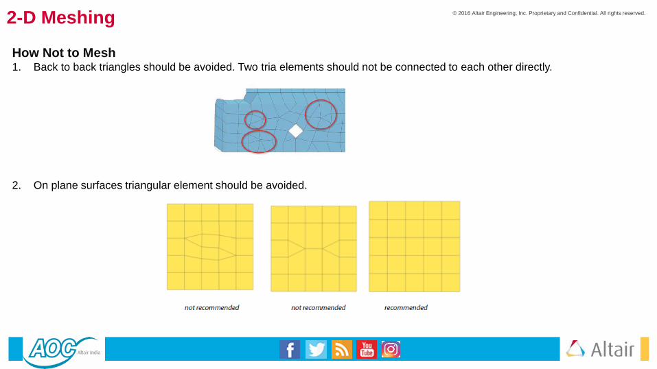
2-D Meshing
How Not to Mesh1. Back to back triangles should be avoided. Two tria elements should not be connected to each other directly.
2. On plane surfaces triangular element should be avoided.

© 2016 Altair Engineering, Inc. Proprietary and Confidential. All rights reserved.
2-D Meshing
3. No mesh transition on constant radius fillets / curvatures
The mesh transition should be carried out on the planer surfaces
4. Avoid tria elements on outer edges or holes
5. What is not acceptable at a professional level What is acceptable.

© 2016 Altair Engineering, Inc. Proprietary and Confidential. All rights reserved.
2-D Meshing
6. Circular holes should be modelled carefully with a washer (1.5 to 2 times diameter) and a minimum of two
layers around the hole.
7. Holes should be modelled with an even number of equally spaced elements:
For a better representation of the hole geometry and smooth mesh flow lines, holes
should be modelled with an even number of elements (like 6, 8, 12,16 etc. rather
than 5, 7, 9 or 13).
8. Nodes should lie properly on the surface, with no deviation (and no kinks).
Switch off the element mesh lines and observe the contour (in particular at curvatures). Kinks as
shown above are not acceptable.

© 2016 Altair Engineering, Inc. Proprietary and Confidential. All rights reserved.
2-D Meshing
9. Follow the feature lines (nodes should lie exactly on the edges).
10. Instead of a zig-zag distribution, a structured or smooth mesh is recommended (nodes aligned in a straight line)
Use of a“smooth” option, provided by most of the commercial software, helps in achieving systematic mesh.
11. For crash analysis, follow the mesh flow line requirement.
12. For crash analysis, rotating quads are not allowed.
13. For Crash analysis, constant mesh size (by using trias) is preferred (due to a minimum element length and a time step criteria).

© 2016 Altair Engineering, Inc. Proprietary and Confidential. All rights reserved.
3-D Meshing
When to Use 3-D Elements
3-D elements should be used when all dimensions are comparable.
x ~ y ~ z
Element shape – Tetra, penta, hex, pyramid
Additional data from user – Nothing
Element type – Solid
Practical applications : Gear box, engine block, crankshaft, etc.

© 2016 Altair Engineering, Inc. Proprietary and Confidential. All rights reserved.
3-D Meshing
DOFs For Solid Elements
2-D thin shell and 1-D beam element supports 6 dofs, but all solid elements have only 3 translational dofs (no rotational dof )
i.e. a 10 noded tetra element has total of 10 x 3 = 30 dofs
Why does a solid element have only 3 translational and no rotational dofs (Physical interpretation)?
Consider a piece of paper (2-D geometry) or long steel scale (1-D geometry). It could be easily bent and twisted (rotational dof
). But now consider a solid object like a duster or a paper weight. It could not be subjected to very high bending or torsion
stiffness. Hence, solid elements have been formulated with 3 translational dofs and no rotational dofs.
© 2016 Altair Engineering, Inc. Proprietary and Confidential. All rights reserved.
3-D Meshing
How Not to Mesh
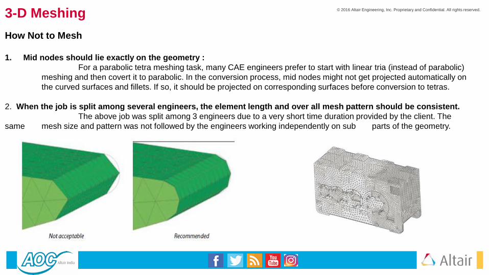
1. Mid nodes should lie exactly on the geometry :
For a parabolic tetra meshing task, many CAE engineers prefer to start with linear tria (instead of parabolic)
meshing and then covert it to parabolic. In the conversion process, mid nodes might not get projected automatically on
the curved surfaces and fillets. If so, it should be projected on corresponding surfaces before conversion to tetras.
2. When the job is split among several engineers, the element length and over all mesh pattern should be consistent.
The above job was split among 3 engineers due to a very short time duration provided by the client. The
same mesh size and pattern was not followed by the engineers working independently on sub parts of the geometry.

© 2016 Altair Engineering, Inc. Proprietary and Confidential. All rights reserved.
3-D Meshing
3. Minimum 2 elements on the fillets for tetra meshing :
Elements at fillets and curved surfaces usually fail in the jacobian/distortion element check. The manual
adjustment for improving the element quality results in mesh deviation from the geometry and visible kinks. This could
be avoided by modeling the fillets with 2 or more elements.
4. For brick meshing, a minimum of 2 elements across the thickness should be used:
A single element leads to a poor interpolation and thus affects the accuracy of the results. A minimum of 2
elements across any thickness is recommended. The exception is NVH applications, where stress is not the
main criteria, but the representation of the mass and stiffness (with the least dofs) is the main criteria.
5. Use of tetra / pyramid elements while brick meshing :
Some clients allow for a few tetra elements during brick meshing. Also some software and analysis types
support pyramid elements. Use of tetra and pyramid elements can make the life of a brick mesher tolerable. It’s good practice
to clarify the instructions for the use of these elements from the client.

© 2016 Altair Engineering, Inc. Proprietary and Confidential. All rights reserved.
3-D Meshing
6. Modeling a sheet metal part with 3-D elements:
For sheet metal or very small thickness parts, 2-D shell elements are better suited and recommended.
Its not like we can not use a 3-D mesh, but it will result in a very high number of nodes and elements. Consider the
following sheet metal part (200 x 200 x 2 mm). We will mesh the same part with 3-D parabolic tetra elements and 2-D quad-
4 (linear) elements using the same element length and compare the number of nodes and elements needed.
7. Limitation of 1-D element and advantage of 3-D meshing:
Fillets, cutouts and complicated geometry features cannot be represented accurately by 1-D elements.
3-D elements, because of 3 dimensions, can capture all the minute details accurately. For example, consider the
following shaft. It is very difficult to capture the key way slot and variable fillet using 1-D elements. Instead 3-D meshing is
recommended for such applications.

© 2016 Altair Engineering, Inc. Proprietary and Confidential. All rights reserved.
Element Quality and Checks
Element quality is a subject often talked about and never fully understood. The reason for this is complex but is related
to the fact that quality is relative and the solution, by definition, is approximate. In the formulation of finite elements a local
parametric coordinate system is assumed for each element type and how well the physical coordinate systems, both element and
global, match the parametric dictates element quality. Below you see some graphics representing element quality and you should
attempt to follow them, however, there will be a point of diminishing return if you try too hard to get every element within the
acceptance criteria. Your judgment is your only guide in those cases. Always perform quality checks on the meshes you create.
Check with “local experts” regarding the appropriate values for each element type required by your element checking computer
programs. Be aware that, in these situations, “correct” answers can vary a great deal as illustrated in the following table where
the range between “OK” and “very poor” is quiet wide.
Solid elements use the determinant of the Jacobian Matrix and compare to the ideal value.
Some common element quality measures are detailed below
© 2016 Altair Engineering, Inc. Proprietary and Confidential. All rights reserved.
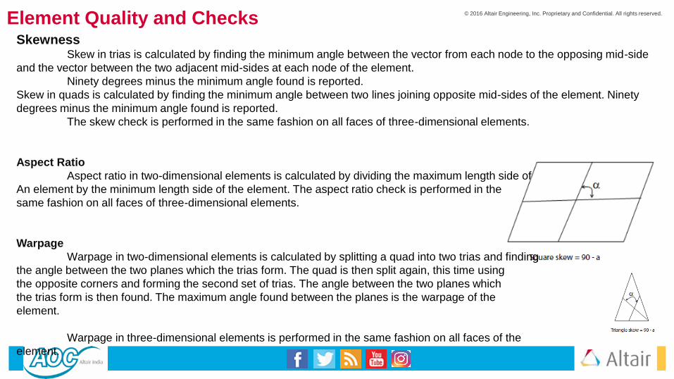
SkewnessSkew in trias is calculated by finding the minimum angle between the vector from each node to the opposing mid-side
and the vector between the two adjacent mid-sides at each node of the element.
Ninety degrees minus the minimum angle found is reported.
Skew in quads is calculated by finding the minimum angle between two lines joining opposite mid-sides of the element. Ninety
degrees minus the minimum angle found is reported.
The skew check is performed in the same fashion on all faces of three-dimensional elements.
Aspect Ratio
Aspect ratio in two-dimensional elements is calculated by dividing the maximum length side of
An element by the minimum length side of the element. The aspect ratio check is performed in the
same fashion on all faces of three-dimensional elements.
Warpage
Warpage in two-dimensional elements is calculated by splitting a quad into two trias and finding
the angle between the two planes which the trias form. The quad is then split again, this time using
the opposite corners and forming the second set of trias. The angle between the two planes which
the trias form is then found. The maximum angle found between the planes is the warpage of the
element.
Warpage in three-dimensional elements is performed in the same fashion on all faces of the
element.
Element Quality and Checks

© 2016 Altair Engineering, Inc. Proprietary and Confidential. All rights reserved.
Element Quality and Checks
2-D Quality Checks
Ideal shape for quad elements – Square
Ideal shape for triangular elements – Equilateral triangle
Different quality parameters like skew, aspect ratio, included angles, jacobian, stretch, etc. are the measures of how
far a given element deviates from the ideal shape. A square means that all of the angles are 900 with equal sides, while an
equilateral triangle has all angles at 600 with equal sides. Some of the quality checks are based on angles (like skew and
included angles), while others on side ratios and area (like aspect and stretch).
To reduce the solution time, elements are mapped to a local coordinate system (individual for every element at the
centroid), instead of using a single coordinate system (global). The effectiveness of this transformation is checked by the
jacobian and distortion. Ideally all the nodes of a quad element should lie in the same plane, but because of curvatures and
complicated geometry profiles, that is not possible. The measure of the out of plane angle is the warp angle.
Warp angle: warp angle is the out of plane angle
Ideal value = 00 (Acceptable < 100).
Warp angle is not applicable for triangular elements.
It is defined as the angle between the normals to two planes formed by splitting the quad element along the diagonals. The
maximum angle of the two possible angles is reported as the warp angle.

Element Quality and Checks
Aspect = maximum element edge length / minimum element edge lengthIdeal value = 1 (Acceptable < 5).
Skew :Ideal value = 0 (Acceptable < 450)
Skew for quadrilateral element = 900 minus the minimum angle between the two lines joining the opposite mid-sides of the element (α).
Skew for triangular element = 900 minus the minimum angle between the lines from each node to the opposing mid-side and between the two adjacent mid-sides at each node of the element
Jacobian:Ideal value = 1.0 (Acceptable > 0.6 )
In simple terms, the jacobian is a scale factor arising because of the transformation of the coordinate system. Elements are transformed from the global coordinates to local coordinates (defined at the centroid of every element), for faster analysis times.
Included angles :Skew is based on the overall shape of the element and it does not take into account the individual angles of a quadrilateral or
triangular element. Included or interior angle check is applied for individual angles.
Quad Ideal value = 900. (Acceptable = 450 < θ <1350)Tria: Ideal value = 600 (Acceptable = 200 < θ < 1200)

© 2016 Altair Engineering, Inc. Proprietary and Confidential. All rights reserved.
Element Quality and ChecksMinimum element length :
This is a very important check for crash analysis (time step calculations). It is also applied in general to check for the minimum feature
length captured and the presence of any zero length element.
Chord deviation :
This helps in determining how well curvatures have been modeled. It is defined as the distance between the mid node of an
element edge to the curved surface. It is only applicable for linear elements.
How to improve the quality of poor elements?1) Manual adjustment: This is done by translating the nodes manually or remeshing in the poor mesh region. This method
consumes lot of time and was the only technique available for years.
2) Drag node: The user has to drag the nodes of the failing elements. It works faster and the advantage is that it
instantaneously shows tje effect of dragging the node on all the attached elements.
3) Auto quality improvement programs: This is the latest option for quality improvement. The user has to submit the mesh
for quality improvement and a software program runs in the background to improve the elements
quality automatically.
Other Checks for 2-D Meshing
1) Element free edges :
What is a free edge ?
Any single quad element has 4 free edges.
Two elements
In the case above, the middle edge is shared and is no longer a free edge.
For a real life FE model, free edges should match with the geometry outer edges / free edges.
Any additional free edges are an indication of unconnected nodes.
© 2016 Altair Engineering, Inc. Proprietary and Confidential. All rights reserved.
Element Quality and ChecksDuplicate element :
Mistakes during operations like reflect or translate can result in duplicate elements. These duplicate elements do not
cause any error during the analysis but increase the stiffness of the model and results in smaller displacements and stresses. For
example. consider a simple plate (thickness = 2 mm) subjected to a tensile load. Assume that due to some meshing operation all
the elements are duplicated. If the analysis is carried out then it will show half the stress and displacement.
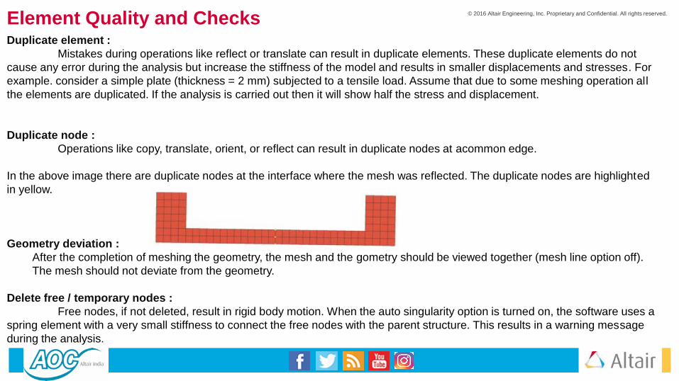
Duplicate node :
Operations like copy, translate, orient, or reflect can result in duplicate nodes at acommon edge.
In the above image there are duplicate nodes at the interface where the mesh was reflected. The duplicate nodes are highlighted
in yellow.
Geometry deviation :
After the completion of meshing the geometry, the mesh and the gometry should be viewed together (mesh line option off).
The mesh should not deviate from the geometry.
Delete free / temporary nodes :
Free nodes, if not deleted, result in rigid body motion. When the auto singularity option is turned on, the software uses a
spring element with a very small stiffness to connect the free nodes with the parent structure. This results in a warning message
during the analysis.

© 2016 Altair Engineering, Inc. Proprietary and Confidential. All rights reserved.
Element Quality and ChecksRenumber nodes, elements, properties etc. before export operation :
Frequent import /export operations could lead to a very large number for the nodes and element IDs. Some software
refuse to read the file if the node/element IDs are greater than a specific limit. This could be avoided by renumbering the
nodes, elements etc.
Observe type, family and number of elements (element summary for complete model) :
The mesh should be checked carefully prior to the export operation, as well as after importing it in the external solver
for element type, family, numbers, etc. Sometimes due to a translator problem, if properties are not defined properly, or for non
supportive elements, either the elements are not exported at all or the family is changed (like membrane elements converted to
thin shell, etc.). Plot, trace lines, element free edges, and free faces, if any, should be deleted.
Check Mass ( Actual mass Vs FE model mass ) :
When a prototype or physical model of the component is available, the FE model mass should be compared with the
actual mass. A difference means that there are missing or additional components, or improper material or physical properties.
Free-Free run or dummy linear static analysis :
Before delivering the final mesh to the client, a free–free run should be performed. 6 rigid modes indicate that all the
parts in the assembly are properly connected to each other. In the case of a single component meshing job, a linear static
analysis with dummy boundary conditions should be carried out.
Request your colleague to check the model :
Due to continually working on the same project, our mind tends to take some of the things for granted and there is a
possibility of missing some of the points. It is a good practice to get it cross checked by your colleague prior to final delivery.

© 2016 Altair Engineering, Inc. Proprietary and Confidential. All rights reserved.
Element Quality and Checks
Quality Checks for Tetra Meshing
Tetra Collapse:
Ideal Value = 1.0 (Acceptable > 0.1)
Tetra collapse = h * 1.24 / A
(Defined as the distance of a node from the opposite face divided by the area of the face multiplied by 1.24)
Other Checks for Tetra Meshing
Quality checks for 2-D tria elements: Before converting trias to tetras, all the quality checks as
discussed for shell elements should be applied.
Free edges: Conversion from tria to tetra is possible only when there are no free edges. No free
edges indicate the mesh is enclosing a volume.
T-connections: The mesh model should not contain any T-connection.

© 2016 Altair Engineering, Inc. Proprietary and Confidential. All rights reserved.
Consistent Shell normals: Before converting trias to tetras, the shell normals should be corrected. Some software do not allow shell to solid conversion unless the
normals of all the elements are properly aligned.
Geometry deviation: After the completion of meshing, the geometry as well as the mesh should be viewed together (mesh line option off). The mesh should not
deviate from the geometry. In the process of quality improvement (in particular for distortion/jacobian on curved surfaces or fillets), sometimes nodes get translated too
far away from the geometry and is not acceptable.
2-D tria elements should be deleted before the final submission : It’s a common mistake to export 2-D shell elements along with tetra mesh in the final delivery.
Brick Mesh Quality ChecksThe ideal shape for a brick element is a cube. Various quality criteria check how far a given element deviates from the ideal shape.
Warp angle:
Ideal value = 0 (Acceptable <300)
Warp angle is calculated on faces (quadrilateral) of a hex element. It is the angle between the planes that form by splitting the quad element.
Jacobian:
Ideal value = 1.0 (Acceptable > 0.5)
In simple language, the jacobian is a scale factor arising because of the transformation of the coordinate system. Elements are transformed from global to local
coordinates to reduce the solution time.
Aspect ratio:
Ideal value =1.0 (Acceptable < 5)
Aspect ratio = max. edge length / minimum edge length.
Quad face included angles: 450 < θ < 1350
Tria face (wedge / penta elements) included angles: 200 < θ < 1200
% of Pentas : Acceptable < 5 %
Element Quality and Checks

© 2016 Altair Engineering, Inc. Proprietary and Confidential. All rights reserved.Element Quality and ChecksOther Checks for Brick Meshing
Free faces
A free face check is the most important check for brick meshing. A single brick element has 6 free faces. Free faces of
the mesh should match with the outer surfaces (skin) of the solid part. Any extra (inside) faces indicate that either nodes are not
connected properly or there are mismatching elements.
Converting free faces to tetras
For complicated geometries, checking the internal free faces could consume lot of time. A quick shortcut is to convert
the free faces to a tetra mesh. Successful conversion indicates that the brick mesh is ok and there are no internal faces.

© 2016 Altair Engineering, Inc. Proprietary and Confidential. All rights reserved.
Material and Property Information
Material Classification

© 2016 Altair Engineering, Inc. Proprietary and Confidential. All rights reserved.
Material and Property InformationMaterial Properties

© 2016 Altair Engineering, Inc. Proprietary and Confidential. All rights reserved.
India EDU Support Team Contacts
• Pune#701-707, City Towers,
Dhole Patil Road,
Pune 411 001
• Bangalore Mercury 2B Block, 5th Floor,
Prestige Tech Park Sarjapur Marathahalli
Outer Ring Road Bangalore
Offices Also in Delhi, Hyderabad & Chennai
Website - www.altairhyperworks.in/aoc
Email ID – [email protected]