antifouling and enhancing pool boiling by tio2 coating surface in nanometer scale thickness
TRANSCRIPT

Antifouling and Enhancing Pool Boiling by TiO2
Coating Surface in Nanometer Scale ThicknessWang Yan and Wang Lin-lin
School of Chemical Engineering and Technology, Tianjin University, Tianjin 300072, China
Liu Ming-yanSchool of Chemical Engineering and Technology, Tianjin University, Tianjin 300072, China, and
State Key Laboratory of Chemical Engineering, Tianjin 300072, China
DOI 10.1002/aic.11345Published online October 25, 2007 in Wiley InterScience (www.interscience.wiley.com).
The accumulation of unwanted crystallization deposits on heat transfer surface con-siderably reduces the efficiency of heat transfer in heat exchangers, especially in theevaporators with vapor–liquid boiling flows. To mitigate the fouling, some measureshave been taken including utilizing low-energy surfaces made by a few kinds of sur-face-coating techniques. In this article, novel applications of TiO2 material in inhibi-ting deposits on heat transfer surface as well as in enhancing pool boiling were devel-oped with nanometer surface engineering method. TiO2 coatings with different layerthicknesses in nanometer scale were prepared by applying vacuum coating techniqueand were characterized with respect to contact angle, surface free energy, roughness,film thickness, topography by contact angle analyzer, scanning electron microscopy(SEM), and atomic force microscopy (AFM), respectively. Distilled water pool boilingand CaCO3 water solution fouling experiments in pool boiling system were performedon these coating surfaces and antifouling and heat transfer enhancement rules wereinvestigated. The results indicate that all TiO2 coating surfaces can avoid CaCO3 de-position, and fouling induction period of TiO2 coating surface in pool boiling with filmthickness of 80 3 1029 m is about 50 times longer than that of the untreated or pol-ished surface in the present experimental conditions. On the other hand, pool boilingwas enhanced on some TiO2 coating surfaces with film thickness in nanometer scale,and heat transfer inhibiting was also observed with certain coating thickness. � 2007
American Institute of Chemical Engineers AIChE J, 53: 3062–3076, 2007
Keywords: nanometer, titanium oxide, vacuum coating, surface free energy, contactangle, SEM, AFM, fouling, pool boiling, enhancement
Introduction
Evaporators or evaporation concentrators are widely uti-lized in the process industry. However, fouling deposition onheat transfer surface and low process transfer efficiency are
two unsolved problems in these heat exchangers. Fouling orscale is generally referred to the accumulation of undesirabledeposits in solid phase or soft mud state on heat transfer sur-faces in heat exchangers. The thermal conductivity of foulinglayer formed on heat transfer surface is low, which canincrease the resistance to heat transfer and will reduce theeffectiveness of heat exchangers.1–6 To inhibit or minimizescale deposition, a number of measures have been suggested,such as cleaning equipment with water or chemistry cleaning
Correspondence concerning this article should be addressed to Liu Ming-yan [email protected].
� 2007 American Institute of Chemical Engineers
AIChE JournalDecember 2007 Vol. 53, No. 123062

agent, adding antifouling additive to the system, onlinecleaning with fluidized particles, avoiding fouling with elec-tric, magnetic, and sound fields, developing nonfouling sur-face by using surface engineering technique, etc.7 One of thedesired approaches to reduce scale adhesion is to alter theproperty of the heat transfer surface to make it less attractivefor the scale, so that fouling can be removed easily from thesurface by boiling or flowing fluids. Since the surface freeenergy of a solid surface gives a direct measure of interfacialattractive forces, the adhesion force is largely dependent onthe surface free energy of the heat transfer materialsinvolved. Therefore, developing low free energy surface isone of the most potential antifouling methods and theresearch in this area is quite active in recent years. Mostinvestigations on this area in pool or flow boiling systemsdemonstrate that the surface free energy has a significantinfluence on fouling adhesion on heat transfer surface andlow-energy surfaces can significantly reduce the formation offouling compared with the untreated or polished surfaces.8–20
Among these explorations, the most systematic and out-standing work was performed under the MODSTEEL projectsupported financially by European Community. In the pro-ject, various surface modification techniques including ionimplantation, diamond-like carbon sputtering, plasmaenhanced chemical vapor deposition, and autocatalysis wereapplied to reduce the fouling of process equipment in thedairy industry. The stainless steel surfaces were treated andcharacterized according to the chemical composition, rough-ness, topography, and wettability. For thick modified layers(10,000 3 1029 m), only the elements of the coating weredetected at the surface, whereas for thin layers (100–2500 31029 m) the surface composition determined was that of thestainless steel substrate. The roughness of the 2R surfaceswas �30–40 3 1029 m and not altered by the modificationtechniques (except for the Ni-P-PTFE coating, 53–100 31029 m). For the 2B surfaces an increase in roughness wasobserved (about 48–550 3 1029 m). DLC sputtering (about450 3 1029 m) and Ni-P-PTFE coating (about 230 3 1029
m) produced surfaces with the highest roughness. All modi-fied surfaces revealed a similar surface topography with theexception of the Ni-P-PTFE coating, for which the coatingmasked the underlying steel topography. Regarding the wett-ability, the SiOx-plasma CVD and Ni-P-PTFE coating tech-niques produced the most hydrophilic and hydrophobic surfa-ces, respectively.16 These modified stainless steel-based sur-faces were evaluated according to their fouling behavior fordifferent dairy products under different conditions. Aqueoussolutions that simulate milk were used to study the foulingbehavior during pasteurization. The results showed that forthe nonmicrobiological deposits the Ni-P-PTFE surface wasthe most promising one, since it generally promoted less de-posit build-up and was the easiest to clean. On the otherhand, for bacterial adhesion, the most suitable surface wasthe ion-implanted surface, which also showed less sporesafter the cleaning process.20
The surface techniques applied in these studies include ionimplantation, magnetron sputtering, ion plating, electroplat-ing, electroless plating, selfassembling, dipping, liquid phasedeposition etc. And some potential coatings materials are flu-orine, fluorinated diamond-like carbon, and Ni-P-PTFEetc.9,10,14,15 However, there are still some key questions to be
answered for the surface with additional coatings. For exam-ple, how does the antifouling effectiveness vary with theincrease of the coating thickness? Under what coating thick-ness, can the additional thermal resistance to heat transferwith low conductivity layer be ignored? And under whatcoating thickness, can boiling heat transfer be enhanced onthese antifouling surfaces? As for the surface without addi-tional film layer, one of the concerned issues is how to keepthe effectiveness and lastingness of the antifouling lowenergy surface.
On the other hand, much progress on boiling heat transferenhancement has been made in the past about 50 years, andthe enhancement methods include passive, active, and com-pound enhancement techniques.3,21 Among the passive tech-niques, surface enhancement has been emphasized. Since thefirst high-performance heater surface configurations werepatented in the late 1960s, a great variety of evaporator tubeswith enhanced surfaces have been developed, that can be di-vided in two main groups, one based on integral-fin tubeswith modified fins to form reentrant grooves or tunnels(‘‘structured surfaces’’), and the other based on plain tubeswith sintered, plasma spraying or flame spraying porous me-tallic matrix bonded to the tube surface (‘‘coated porous sur-faces’’). Such coatings possess heat transfer coefficients up to10 times those for smooth untreated surfaces and there is anoptimum coating thickness to achieve maximum heat transfercoefficient.22–26 Pool boiling heat transfer from nano-poroussurface immersed in a saturated FC-72 dielectric fluid hasbeen experimentally studied at atmospheric pressure lately.The data obtained from nano-porous surface of thicknessabout 70 3 1026 m made from aluminum oxide were com-pared with that of a plain aluminum surface of thicknessabout 105 3 1026 m. It was found that there is a reductionof about 30% in the incipient superheat for the applied powerfor nano-porous surface over plain surface.27
Recently, TiO2 coatings with superhydrophilicity byexposing the surface to UV ray were explored to enhancepool boiling by using dipping and magnetron sputtering,and it is found that the critical heat flux (CHF) of TiO2-coated surface is about two times larger than that of non-coated one, and the temperature at minimum heat flux(MHF) for the superhydrophilic surface is higher by 100 Kthan that for the normal one and the superhydrophilic sur-face can be an ideal heat transfer surface.28–30 The poolboiling on a superhydrophobic coating surface was alsoinvestigated. The surface was coated with fine particles ofnickel and PTFE by means of electrolytic plating with con-tact angle to water of 1528 in room temperature and thick-ness of 10 3 1026 m. It seems from the primary resultsthat the boiling feature on superhydrophobic surface is quitedifferent from that of usual surfaces. The stable film boilingoccurs in very small superheating, and there is no nucleateboiling region. The bubbles generated on the surface coa-lesce into a vapor film without departing from the surface.The stable vapor film exists even at a surface temperaturebelow the saturation temperature.31 It indicates that super-hydrophilic surface is advantageous to boiling or evapora-tion but superhydrophobic surface is not.
It is noteworthy that antifouling function should also beconsidered on developing enhanced surfaces21 because formost boiling evaporation processes, fouling on heat transfer
AIChE Journal December 2007 Vol. 53, No. 12 Published on behalf of the AIChE DOI 10.1002/aic 3063

surface is easy to be formed. In this situation, hydrophobicsurface or low energy surface may be favorable.
It is well known that the nanometer material has uniqueselfcleaning effect, which has been applied to the glass win-dows of buildings, car coatings, clothes, and so on. Andrecent studies show that the main reasons resulted in the self-cleaning functions of natural bio-surfaces such as lotusleaves, rice leaves, cicada wings, and water strider legs werecontributed to their superhydrophobic natures and the micro-and nano-scale structures.32 Hence, increasing the hydropho-bicty of the heat transfer surface with nanometer materialmay improve the nonfouling characteristic. Meanwhile, theimproved antifouling surfaces may enhance boiling heattransfer as well if the surface coating thickness is in nanome-ter order. In our very recent work, TiO2 coating surface withlayer thickness in micrometer scale was prepared by liquidphase deposition (LPD) method and flow boiling enhance-ment and antifouling on such coating surfaces were investi-gated and confirmed.33
The main goal of this work is to explore the antifoulingand pool boiling heat transfer enhancement characteristics onlow energy surfaces of TiO2 coating with layer thickness innanometer scale. First, low energy surfaces of TiO2 coatingswith different layer thicknesses in nanometer order were pre-pared by applying vacuum coating technique. Second, theywere characterized by using contact angle analyzer, SEM,and AFM. Finally, distilled water pool boiling and CaCO3
water solution fouling experiments in pool boiling systemwere performed on these coating surfaces to investigate theantifouling and heat transfer enhancement effects.
Preparation and characterization of TiO2
coating surfaces
Preparation of TiO2 Coating Surfaces. Three types oftested surfaces were prepared: untreated, polished, and coatedsurfaces, and they are all red copper-based surfaces. For thepolished surface, the modifications consist of finishing byusing emery wheel with emery grits of Nos. 340 and 600,polishing by using polishing wheel with grinding pastes ofemery sand particles in diameters of 1 3 1026 m and 0.5 31026 m, removing oil by using 10% NaOH water solutionimmersion and acetone ultrasonic cleaning, cleaning withdeionized water, and airing with natural air. TiO2 coatingswere prepared on polished red copper-based surfaces usingvacuum coating technique.
The vacuum coating on polished surface with TiO2 mate-rial was carried out at Tianjin University, China, using aZZS700-2/G type vacuum box coater made by Cheng-duNan Guang Industry. The vacuum coating is a physical vapordeposition (PVD) process at a high vacuum. The ZZS700-2/G type vacuum box coater is composed of main machinebox, control-electricity tank, and high-voltage control tank.The final vacuum is 9.5 3 1025 Pa with liquid nitrogen, 5 31024 Pa without liquid nitrogen. In the main machine box,there is an evaporation chamber with the diameter of 0.71 mand height of 0.85 m, a workpiece frame which can rotate inthe maximum number of revolution per minute 30 driven bya direct current electric motor and a few jigs with diameterof 0.64 m for both spherical cap and flat workpieces, two E-type magnetic deflection electron beam evaporation sources
with electron gun power of 6, 8, or 10 kW with a X–Y mag-netic deflection scan unit, an electron gun filament and abeam flow control unit, a gas extracting system and a coolingsystem etc. The workpiece surface to be coated (the sub-strate) and the coating material (in the evaporation source) ofhigh-purity (99.999%) TiO2 are arranged in the vacuumevaporation chamber of the main machine box. During vac-uum coating, the thermoelectrons emitted from the filamentare accelerated when passing through the electric field andbombard the evaporation material surface after beingdeflected in their electronic orbits in certain angle affectedby the electromagnetic field and focused. The evaporationmaterial is heated to a rather high temperature by thefocused, accelerated high-energy electron beam and evapo-rates in the high vacuum chamber. At last vaporized TiO2
material deposits on the substrate with very thin film layer.The coating thickness is monitored by the quartz crystalthickness monitor and controlled by the coating time. Thesubstrate is not heated during vacuum coating and its temper-ature is about ambient temperature.
In this work, TiO2 coating surfaces with different layerthicknesses in nanometer scale were formed on the red cop-per substrates with diameter of 0.11 m and thickness of0.006 m to study the effect of coatings in nanometer orderthickness on antifouling and enhancing pool boiling heattransfer. Meanwhile, small rectangular coating samples basedon the red copper plate with the length of 0.01 m, width of0.01 m, and height of 0.006 m were simultaneously preparedfor easy measurement and analysis. The vacuum coatingparameter and coating thickness are shown in Table 1. It canbe found that the real coating thickness is close to thedesigned and varies with the coating time. The thicknessranges from 20 to 100 3 1029 m. The real coating thicknessis the thickness displayed on the digital control board in thecoating instrument. Typical AFM measurement value of coat-ing thickness is near the same as that displayed on the instru-ment control board, which is illuminated in Figure 7.
Measurement of contact angle and calculation of freeenergy of TiO2 coating surface
The contact angles of untreated, polished, and coated sur-faces with different layer thicknesses of TiO2 were measuredby using JY-82 contact angle analyzer and the distilled waterand glycerine were used as titers. The measurement of eachcontact angle was repeated three times and the averages ofdifferent coating surfaces are shown in Table 2. To have aqualitative grip of such coating surfaces, typical digital pho-tos of coating surfaces and distilled water drops on these
Table 1. Vacuum Coating Parameter and TiO2 CoatingThickness
Vacuum/31023 Pa
Coatingtime/s
Evaporatingvelocity/
310210 m s21
DesignedCoatingthickness/31029 m
Real Coatingthickness/31029 m
2.5 1653 0.6 100 99.92.6 1763 0.5 80 80.44.1 1553 0.3 60 60.52.2 800 0.5 40 39.92.8 166 1.2 20 20.7
3064 DOI 10.1002/aic Published on behalf of the AIChE December 2007 Vol. 53, No. 12 AIChE Journal

surfaces taken in natural light are illustrated in Figure 1. Thecolor of TiO2 coating surface gets darker with increase ofthe film thickness, as shown in Figure 1a. Table 2 shows thatthe contact angle of untreated surface is lowest and polishingtreatment increases the contact angle of surface; coating pro-cess further enlarges the contact angle and thus improves thehydrophobicity; the contact angle of coating surface increasesslightly with the decrease of the coating thickness and thecontact angle of the thinnest coating surface with thicknessof 20 3 1029 m is the largest one.
The surface free energy was calculated on the measure-ment data of contact angles of coating surfaces according theYoung’s equation, Owense equation, GEOm method, andGEOs method34 and also given in Table 2. It can be seenfrom Table 2 that compared with the untreated and polishedsurfaces, coating process reduces the surface free energygreatly due to the appearance of the TiO2 material in thethickness of nanometer order on the red copper surface.However, the surface free energy reduction is not obviouswith the decrease of the thickness of coating surface underthe present range of film thickness. Figure 2 clearly illumi-nates this variation tendency, in which, 220 3 1029 m and
0 3 1029 m of abscissa values, not being the concrete valuesof coating thickness, only represent the untreated and pol-ished heat transfer surfaces, respectively. The effect of coat-ing thickness on surface energy seems unusual because sur-face energy describes the interaction of the fluid with the firstcoating of the substrate, but this trend was also found in theTiO2 coating in micrometer scale made by LPD method.33
One reason is that the surface free energy is determined bythe properties of the TiO2 nanometer scale material itself andthese properties such as density and hardness change withthe increase of the coating thickness. When the coating isthin, it may not be the film layer traditionally referred to.Meanwhile, the varying range of the coating thickness is notwide in this work and the surface energy variation with theincrease of the layer thickness is very weak.
Characterizations of TiO2 coating surfaces bySEM and AFM
SEM. To get the topography information of TiO2 coatingsurface, SEM measurements were performed first. Figure 3shows the SEM images of untreated, polished, and TiO2
coating surfaces in micrometer scale with two different filmthicknesses of 20 3 1029 m and 80 3 1029 m before thepool boiling and fouling experiments, respectively. Thecoated surfaces (Figures 3c, d), like polished one (Figure3b), are very glazed, which is quite different from theuntreated one (Figure 3a) that is scraggly. Figure 3 indicatesthat coating TiO2 material on polished surface has no greateffect on the surface morphology compared with the polishedone, and all coated surfaces seem very uniform in film thick-ness. Other coated surfaces hold the same surface morpholo-gies on the SEM images as the ones mentioned earlier andwill not be shown again.
Table 2. Contact Angle and Surface Free Energy of TiO2
Coating Surfaces
d/ 3 1029 m hw/8 hg/8 c/ 3 1023 Jm22
Untreated 58.2 100.0 207.7Polished 60.8 101.5 199.1100 83.7 115.5 119.880 86.3 118.0 115.460 88.5 120.3 112.440 89.0 120.5 110.120 91.7 121.0 95.5
Figure 1. Digital photos of TiO2 coating surfaces and distilled water drops on the surfaces.
(a) TiO2 coating surfaces with different film thicknesses; (b) distilled water drops on TiO2 coating surfaces with different film thicknesses.(i) 20 3 1029 m; (ii) 40 3 1029 m; (iii) 60 3 1029 m; (iv) 80 3 1029 m; (v) 100 3 1029 m. [Color figure can be viewed in the onlineissue, which is available at www.interscience.wiley.com.]
AIChE Journal December 2007 Vol. 53, No. 12 Published on behalf of the AIChE DOI 10.1002/aic 3065

AFM
To get more detailed information on microstructure ofTiO2 coating surface, AFM is utilized and TiO2 coating sur-face with film thickness of 80 3 1029 m is taken as anexample to find the proper scan area for enough analysis.The scan area change from 100 3 100 (1029 m)2 to 30,0003 30,000 (1029 m)2. Typical two- and three-dimensionalAFM images of TiO2 coating surfaces with coating thicknessof 80 3 1029 m under 2000 3 2000 (1029 m)2 (Figures 4a,b), 10,000 3 10,000 (1029 m)2 (Figures 4c, d), 20,000 3
20,000 (1029 m)2 (Figures 4e, f) scan areas are shown inFigure 4. It can be found from Figure 4 that with the widen-ing of the scan area, surface microcosmic pattern becomesclearer and richer. As shown in Figure 4a, TiO2 coating sur-face consists of ellipsoid or hillock units distributed homoge-neously, which is much like the case of the surface coatedwith fluorinated diamond-like carbon film at the scan area of2000 3 2000 (1029 m)2.15 It seems that to get the microcos-mic pattern, the scan area of 2000 3 2000(1029 m)2 isenough. If further enlarging the scan area, much more infor-mation appears on the AFM images, such as valleys, cracks,and sharp peaks along the surfaces, as shown in Figures 4c,e. The largest ellipsoid in Figure 4e is the cluster of TiO2
crystallites.The data of the root mean square roughness (Rrms) being
the standard deviation of the height values within a given scanarea and difference in height between the highest and lowestpoints on the surface relative to the mean plane (Rmax) givenin the AFM images are utilized to quantify the surface rough-ness. Rrms of 80 3 1029 m TiO2 coating for the four scanareas (100 3 100 (1029m)2, 2000 3 2000 (1029 m)2, 10,0003 10,000 (1029 m)2, and 20,000 3 20,000 (1029 m)2) are 1.03 1029 m, 2.4 3 1029 m, 4.7 3 1029 m, and 5.7 3 1029 m,respectively. These data indicate that with the rising of scanarea, the surface roughness approaches to a steady value innanometer scale. Rmax of 80 3 1029 m TiO2 coating for thefour scan areas are 6.1 3 1029 m, 32.5 3 1029 m, 118.0 31029 m, and 135.7 3 1029 m, respectively. Rmax increaseswhen enlarging the scan area. When the scan area exceeds
Figure 2. Relationship of TiO2 coating thickness andthe surface free energy.
Figure 3. Typical SEM images of untreated, polished, and TiO2 coating surfaces.
(a) untreated; (b) polished; (c) 20 3 1029 m; (d) 80 3 1029 m.
3066 DOI 10.1002/aic Published on behalf of the AIChE December 2007 Vol. 53, No. 12 AIChE Journal

Figure 4. Two- and three-dimensional AFM images of TiO2 coating surfaces with film thickness of 80 3 1029 munder different scan areas.
(a), (c), and (e) are three-dimensional AFM images; (b), (d), and (f) are two-dimensional AFM images; (a) and (b) with scan area of 20003 2000 (1029 m)2; (c) and (d) with scan area of 10,000 3 10,000 (1029 m)2; (e) and (f) with scan area of 20,000 3 20,000 (1029 m)2.[Color figure can be viewed in the online issue, which is available at www.interscience.wiley.com.]
AIChE Journal December 2007 Vol. 53, No. 12 Published on behalf of the AIChE DOI 10.1002/aic 3067

10,000 3 10,000 (1029 m)2, both Rrms and Rmax rise weakly,which indicates that the scan area of 10,000 3 10,000 (1029
m)2 is enough to carried out proper analysis.The data of surface roughness of all heat transfer surfaces
used in this work were obtained by AFM analyses with scanarea of 20,000 3 20,000 (1029 m)2 or 30,000 3 30,000(1029m)2. Two- and three-dimensional AFM images are
shown in Figure 5. The relationship between Rrms or Rmax
and coating thickness is shown in Figure 6.In Figure 6, 220 3 1029 m and 0 3 1029 m of abscissa
values, not being the real values of coating thickness, onlyrepresent the untreated and polished heat transfer surfaces,respectively, and the connection lines of data points are justfor directing the eyes.
Figure 5. Two- and three-dimensional AFM images of all heat transfer surfaces.
(a) and (b) untreated surface; (c) and (d) polished surface; (e) and (f) TiO2 coating surface with layer thickness of 20 3 1029 m; (g) and(h) TiO2 coating surface with layer thickness of 40 3 1029 m; (i) and (j) TiO2 coating surface with layer thickness of 60 3 1029 m; (k)and (l) TiO2 coating surface with layer thickness of 80 3 1029 m; (m) and (n) TiO2 coating surface with layer thickness of 100 3 1029
m. [Color figure can be viewed in the online issue, which is available at www.interscience.wiley.com.]
3068 DOI 10.1002/aic Published on behalf of the AIChE December 2007 Vol. 53, No. 12 AIChE Journal

Figure 5. (Continued)
AIChE Journal December 2007 Vol. 53, No. 12 Published on behalf of the AIChE DOI 10.1002/aic 3069

It can be seen from Figures 5 and 6 that the topography ofuntreated surface (Figure 5a) is most different from the otherheat transfer surfaces and the other heat transfer surfaceshave the similar morphology, including the polished surface.The untreated sample (Figure 5a) exhibits a rugged surfacetopography in which some mountains and valleys areobserved, while other samples reveal more homogeneousappearances full of hillock units along the surfaces. This isin accordance with the roughness values as shown in Figure6, and untreated sample holds the highest Rrms and Rmax,while other samples’ roughness values are near and are inthe nanometer scale. This indicates that vacuum coating pro-cess did not affect the red copper substrate topography sig-nificantly. From two-dimensional images shown in Figure 5,it can be found that with the increase of the coating thick-ness, the real color of the red copper substrate becomes dark.Of course, the TiO2 coating with thickness of 100 3 1029 m
can’t mask all surface features of the red copper support(Figure 5n).
Figure 6 shows that Rrms and Rmax decrease generally,slightly and wavily with the rising of the coating thickness.Among the heat transfer surfaces, 80 3 1029 m coating sur-face has the lowest Rrms, second, 40 3 1029 m coatingsurface.
It is noteworthy that the AFM image measurements in Figure5 were carried out after making the digital photos of distilledwater drops on the heat transfer surfaces, which is differentfrom the measurement condition of AFM images given inFigure 4. Hence, the AFM images and results of surfaceroughness were affected in certain degree by the leftover ofwater drop. For example, for the same coating surface withcoating thickness of 80 3 1029 m, there are more sharp nee-dles when the rectangular coating sample was new (Figure4e) than after it was used for contact angle analysis (Figure5k) in the three-dimensional AFM image. One reason for thisis that the remains of the water drop on the sample mightsmooth the surface, and the other is that the scan location isnot the same. But the variation tendency of surface rough-ness may not largely be affected.
The TiO2 coating thickness is also measured with AFMto test the control accuracy of the vacuum coating processby scanning the brim of the coated samples or the edgebetween the red copper substrate and the coatings. Figure 7shows typical two- and three-dimensional AFM images.The measurement value of film thickness is 80.0 3 1029
m, which is close the datum (80.4 3 1029 m, as shown inTable 1) displayed on the control board during vacuumcoating.
Apparatus and measuring system of pool boiling heattransfer and fouling experiments
The schematic diagram of pool boiling and fouling ex-perimental apparatus and heat transfer block are shown inFigure 8.
Figure 7. Two- and three-dimensional AFM images of TiO2 coating surfaces with layer thickness of 80 3 1029 m byscanning the edge.
(a) Two-dimensional; (b) three-dimensional. [Color figure can be viewed in the online issue, which is available at www.interscience.wiley.com.]
Figure 6. Relationship between surface roughnessand coating thickness of all heat transfersurfaces.
3070 DOI 10.1002/aic Published on behalf of the AIChE December 2007 Vol. 53, No. 12 AIChE Journal
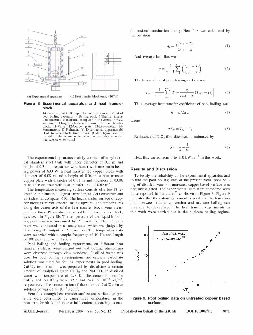
The experimental apparatus mainly consists of a cylindri-cal stainless steel tank with inner diameter of 0.1 m andheight of 0.3 m, a resistance wire heater with maximum heat-ing power of 600 W, a heat transfer red copper block withdiameter of 0.08 m and a height of 0.06 m, a heat transfercopper plate with diameter of 0.11 m and thickness of 0.006m and a condenser with heat transfer area of 0.02 m2.
The temperature measuring system consists of a few Pt re-sistance transducers, a signal amplifier, an A/D converter andan industrial computer 610. The heat transfer surface of cop-per block is mirror smooth, facing upward. The temperaturesalong the center axis of the heat transfer block were meas-ured by three Pt resistances embedded in the copper block,as shown in Figure 8b. The temperature of the liquid in boil-ing pool was also measured by Pt resistance. The measure-ment was conducted in a steady state, which was judged bymonitoring the output of Pt resistance. The temperature datawere recorded with a sample frequency of 10 Hz and lengthof 100 points for each 1800 s.
Pool boiling and fouling experiments on different heattransfer surfaces were carried out and boiling phenomenawere observed through view windows. Distilled water wasused for pool boiling investigations and calcium carbonatesolution was used for fouling experiments in pool boiling.CaCO3 test solution was prepared by dissolving a certainamount of analytical grade CaCl2 and NaHCO3 in distilledwater with temperature of 293 K. The concentrations forCaCl2 and NaHCO3 were 72.2 and 54.6 3 1023 kg/m3,respectively. The concentration of the saturated CaCO3 watersolution of was 65 3 1023 kg/m3.
Heat flux through heat transfer surface and surface temper-ature were determined by using three temperatures in theheat transfer black and their axial locations according to one-
dimensional conduction theory. Heat flux was calculated bythe equation
qi ¼ kTiþ1 � Tiviþ1 � vi
(1)
And average heat flux was
q ¼ kn� 1
Xn�1
i¼1
Tiþ1 � Tiviþ1 � vi
� �(2)
The temperature of pool boiling surface was
Tw ¼ 1
n� 1
Xn�1
i¼1
Ti � viviþ1 � vi
ðTiþ1 � TiÞ� �
(3)
Thus, average heat transfer coefficient of pool boiling was
h ¼ q=DTw (4)
where
DTw ¼ Tw � Ts (5)
Resistance of TiO2 film thickness is estimated by
Rf ¼ 1
h� 1
h0(6)
Heat flux varied from 0 to 110 kW m22 in this work.
Results and Discussion
To testify the reliability of the experimental apparatus andto find the pool boiling state of the present work, pool boil-ing of distilled water on untreated copper-based surface wasfirst investigated. The experimental data were compared withthose reported in literature,35 as shown in Figure 9. Figure 9indicates that the datum agreement is good and the transitionpoint between natural convection and nucleate boiling canbasically be determined. The heat transfer experiments inthis work were carried out in the nucleate boiling regime.
Figure 8. Experimental apparatus and heat transferblock.
1-Condenser; 2-Pt 100 type platinum resistance; 3-Coat ofpool boiling apparatus; 4-Boiling pool; 5-Thermal insula-tion material; 6-Industrial computer 610 system; 7-Viewwindow; 8-Flange; 9-Resistance wire; 10-Heat transferblock; 11-Valve; 12-Copper plate; 13-Level-meter; 14-Manometers; 15-Preheater. (a) Experimental apparatus (b)Heat transfer block (unit, mm). [Color figure can beviewed in the online issue, which is available at www.interscience.wiley.com.]
Figure 9. Pool boiling data on untreated copper basedsurface.
AIChE Journal December 2007 Vol. 53, No. 12 Published on behalf of the AIChE DOI 10.1002/aic 3071

Typical pool boiling images (top view) on polished copperwhen varying heat flux are shown in Figure 10 and manysmall white vapor bubbles with diameter of about 3–6 31023 m can be observed in the images.
Repeated experiments of pool boiling with distilled waterand CaCO3 solution on untreated, polished, and coated surfa-ces were all carried out and the repeatability was good.
Effect of surface coatings on heat transferenhancement in pool boiling
Heat transfer enhancement experiments were performed ina pool boiling system with distilled water.
Figure 11 illuminates the relationship between pool boilingheat transfer coefficient of distilled water and running time. Itcan be found from Figure 11 that, on the one hand, the heattransfer coefficients of various surfaces are basically stablewith extension of pool boiling time. On the other hand, heattransfer enhancement can be observed on TiO2 coating surfa-ces with thicknesses of 20 3 1029 m, 60 3 1029 m, and 80 31029 m compared with those of the untreated surface becauseheat transfer coefficients on these coated surfaces are higherthan those on untreated surfaces, being about 3, 7, and 12%
higher, respectively. However, heat transfer deterioration isalso obtained on TiO2 coating surfaces with thicknesses of 403 1029 m and 100 3 1029 m since on these surfaces heattransfer coefficients are lower than those on untreated surfa-ces, being about 22 and 19% lower, respectively. The resist-ance of TiO2 coatings was estimated on the base of polishedsurface and is shown in Table 3. Negative value of resistanceof TiO2 coating surface indicates that the boiling heat transfercoefficient of the surface is higher than that of polished sur-face and pool boiling on such a coated surface is enhanced.The reasons for the experimental phenomena are complex,because there are so many influence factors on the pool boil-ing process, including the properties of heat transfer surface,distilled water, and heat flux. At specific heat flux and givenproperties of distilled water, the different properties of heattransfer surface, such as the surface free energy, roughness, to-pography, etc. contribute to the variation of the heat transfercoefficient. However, no clear explanations can be obtainedby analyzing the trends shown in Figures 2, 5, and 6 becausethey are not in accordance with the tendency of the heat trans-fer coefficient. Other affecting factors need to be found.
It is well known that the more nucleation spots, the morevapor bubbles, and the more violent the pool boiling. Thepolished surfaces generally provide less nucleation spots thanthe untreated surfaces, and heat transfer coefficient on pol-ished surface should be lower than that on the untreated sur-face. Nevertheless, in Figure 11, pool boiling heat transfercoefficient on untreated surface is lower than that on polishedsurface, which means that polish improves the boiling pro-cess in some degree. This experimental result was alsoobtained in the literature.19 This may result from the activa-tion effects in micrometer scale on the nucleation spots ofthe polish process. Similar variation rules are obtained underother heat fluxes.
Table 3. TiO2 Coating Thickness and Estimated Resistance
d/ 3 1029m Rf 3 106/W21m2 K1
20 24.440 11360 6.3980 222100 80.8
Figure 10. Typical pool boiling images (top view) on polished copper surfaces when varying the heat flux.
(a) q 5 79.8 kW m22; (b) q 5 96.6 kW m22; (c) q 5 110 kW m22. [Color figure can be viewed in the online issue, which is availableat www.interscience.wiley.com.]
Figure 11. Pool boiling heat transfer coefficient vs. run-ning time for different heat transfer surfaceswith distilled water.
3072 DOI 10.1002/aic Published on behalf of the AIChE December 2007 Vol. 53, No. 12 AIChE Journal

Effect of surface coatings on antifouling in pool boiling
Fouling experiments under pool boiling conditions wereperformed with CaCO3 water solution.
Figure 12 shows the experimental results of CaCO3 foul-ing on different heat transfer surfaces, including untreated
surface, polished surface, coated surfaces with different TiO2
coating thickness under various heat fluxes.It is shown in Figure 12 that in nucleate boiling region, all
the TiO2 coating surfaces have excellent antifouling charac-teristics compared with untreated and polished surfacesbecause pool boiling heat transfer coefficient on coated sur-face basically keeps constant within experimental length oftime (about 240,000 s), while those on untreated and pol-ished surfaces drop sharply after only about several hundredminutes and stabilize at low values due to deposits of CaCO3
crystal or fouling on the surfaces. Figure 12 also indicatesthat surface polish enlarges only slightly fouling inductionperiod, while vacuum coating with TiO2 in thickness ofnanometer scale lengthen fouling induction period greatly.The enhancement effect on antifouling can be contributed inlarge degree to low surface free energy of nanometer mate-rial coatings. Since low-energy surface is less prone to adhe-sion of crystal and this leads to a lower fouling growth rateon heat transfer surface and a longer induction period. Atgiven operation conditions and solution properties, the differ-ent properties of heat transfer surface, such as the surfacefree energy, roughness, topography, etc. contribute to the var-iation of the fouling behavior. The roughness value of pol-ished surface is much lower than that of the untreated one.The topography of polished surface is also very differentfrom that of the untreated one. However, it is the surfacefree energy that plays an important role in the formation offouling. The two surfaces hold near the same values of sur-face free energy and it is not surprising that they have almostthe same fouling behavior.
In addition, the higher the heat flux, the shorter the foulinginduction period for untreated surface or polished surface canbe seen in Figures 12a–c, which is easy to be interpreted.
As for the variation rule of pool boiling film coefficientwith coating thickness, a tendency that is similar to that ofpool boiling of distilled water can be found in Figure 12. Thatis to say, pool boiling heat transfer coefficient is not a mono-tonic function of coating thickness variable. As mentionedabove, the physical explanation on such tendency is difficultsince many factors are responsible for this variation, such as
Figure 12. Pool boiling heat transfer coefficients onvarious heat transfer surfaces vs. runningtime in CaCO3 water solution.
(a) q 5 79.8 kW m22; (b) q 5 96.6 kW m22; (c) q 5110 kW m22.
Figure 13. Fouling experiments results on TiO2 coatingsurface with layer thickness of 80 3 1029 min a longer running time.
AIChE Journal December 2007 Vol. 53, No. 12 Published on behalf of the AIChE DOI 10.1002/aic 3073
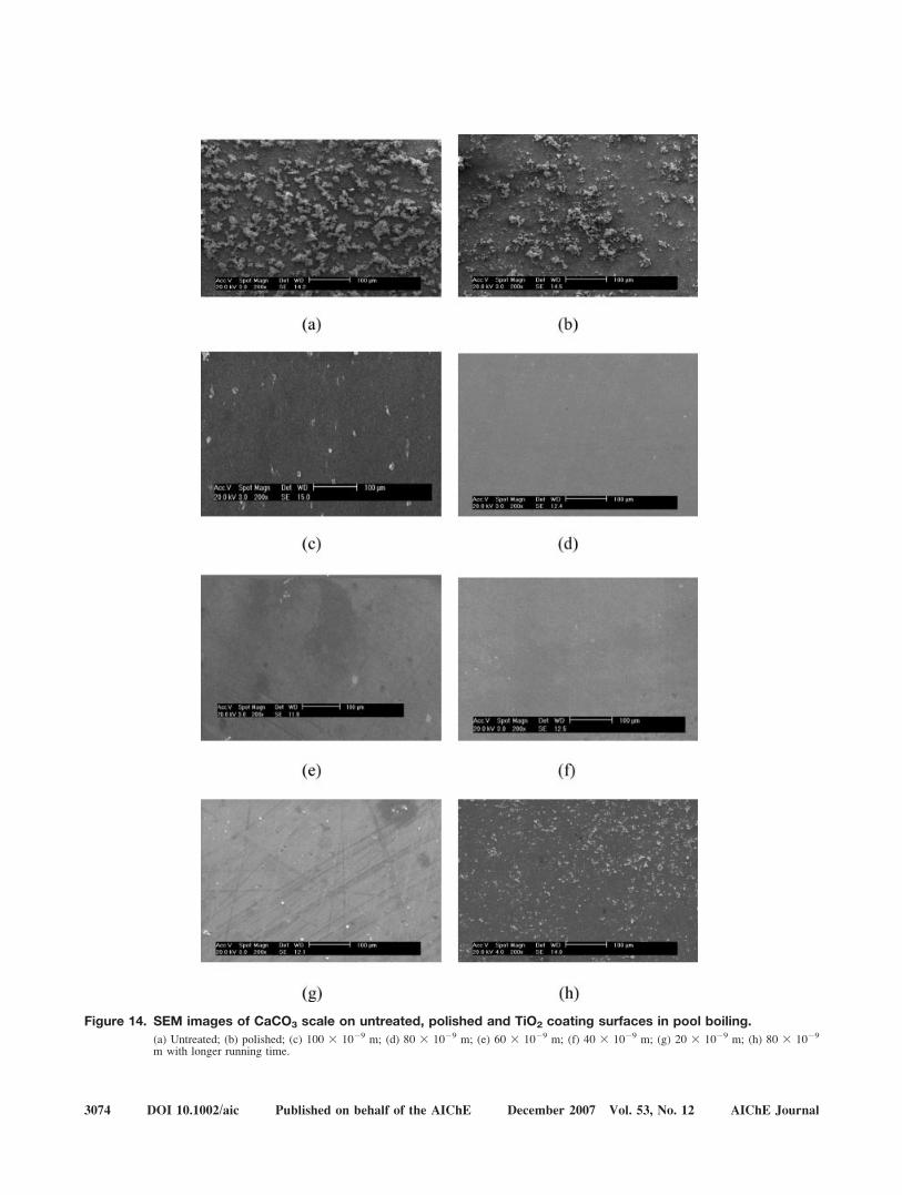
Figure 14. SEM images of CaCO3 scale on untreated, polished and TiO2 coating surfaces in pool boiling.
(a) Untreated; (b) polished; (c) 100 3 1029 m; (d) 80 3 1029 m; (e) 60 3 1029 m; (f) 40 3 1029 m; (g) 20 3 1029 m; (h) 80 3 1029
m with longer running time.
3074 DOI 10.1002/aic Published on behalf of the AIChE December 2007 Vol. 53, No. 12 AIChE Journal

the surface free energy, topography, roughness, coatingmethod, coating material properties, coating inner nanometermicrostructure, nanometer scale effect, etc. The surface freeenergy is not the only factor that affects the boiling heat trans-fer and antifouling behavior of TiO2 coating surface. The sur-face roughness is generally considered to be one of the mostimportant factors that affect the boiling heat transfer process.However, no clear rule can be drawn from the relationshipbetween the surface roughness (Figure 6) and boiling heattransfer coefficient (Figures 11 and 12). All the coating surfa-ces have similar topographies. Fouling experiments wererepeated and good agreements were found. Some other mostpossible factors may be the inner nanometer microstructure ofTiO2 coatings, nanometer effect, the condition of vacuumcoating process etc. that can lead to different coating thermalresistance or thermal conductivity and different vaporizationor boiling mechanism, which needs further identification.
Figures 12a–c indicate that antifouling rules of coated sur-faces are similar for different heat fluxes. Besides, under thepresent experimental conditions, heat transfer coefficient isthe largest when the thickness of the coated surface is 80 31029 m and the coated surfaces with certain film thickness(20 3 1029 m, 60 3 1029 m, and 80 3 1029 m) can notonly inhibit fouling on heat transfer surface but also enhancethe pool boiling heat transfer. However, some coated surfaces(with coating thicknesses of 40 3 1029 m and 100 3 1029
m) can only inhibit fouling, which likes most other coatingsmade of ordinary materials or layer thicknesses.
To investigate the practical durability of the TiO2 coatingsurface, the fouling experiments with longer running timewere carried out on TiO2 coating surface with layer thicknessof 80 3 1029 m. The result shows that heat transfer coeffi-cient of pool boiling on 80 3 1029 m TiO2 coating surfacelasts steadily in a high level about 780,000 s, which is about50 times longer than that on the untreated surface and afterthat it drops suddenly to a low level, as shown in Figure 13.The sharp decrease of pool boiling film coefficient may haveclose relationship with the inherent properties of vacuumcoating surface.
After the boiling fouling experiments, the SEM images ofuntreated, polished, and TiO2 coating surfaces with differentfilm thicknesses are given in Figure 14, respectively. CaCO3
deposits on these surfaces can be investigated by analyzingFigure 14. Figures 14a, b show that a large amount of CaCO3
scale is formed on untreated and polished surfaces and the de-posit of CaCO3 crystal exhibits a packed structure due to thestrong adhesion force between scale and heat transfer surface.On the contrary, there is very little deposit on coated surfaceswith a loose structure partly due to the weak adhesion forcebetween deposit and coated surface. In the mean while, mostTiO2 coating surfaces were not destroyed and keep their origi-nal appearances or surface patterns.
The SEM image of coated surfaces with film thickness of80 3 1029 m after a longer running time is also shown inFigure 14h for comparison, and fouling with loose structureon the surface can be found.
Concluding Remarks
Compared with those of the untreated and polished surfa-ces, surface free energy of the vacuum coating TiO2 surfaces
in nanometer scale thickness drops greatly. However, itreduces slightly when film thickness decreases in nanometerrange. Surface free energy depends largely on the inherentproperty of coating material itself. Compared with that of theuntreated surface, the roughness of the TiO2 coating surfacesincluding that of the polished surface drops significantly.But, the roughness reduces weakly with the increase of thecoating thickness. TiO2 coating surfaces and polished surfacehold the similar morphology, which is very different fromthat of untreated surface.
All TiO2 coating surfaces with thickness in nanometerscale can inhibit fouling significantly partly due to theirlower surface free energy. Even though it deposits on TiO2
coating surfaces after a quite long running time, CaCO3 crys-tal fouling is not serious and exhibits a rather loose structure.The fouling induction period of the TiO2 coating surface inpool boiling with film thickness of 80 3 1029 m is about 50times longer than that of the untreated or polished surface inthe present conditions.
Boiling heat transfer enhancement was observed on TiO2
coating surface with certain coating thickness, such as withfilm thicknesses of 20 3 1029 m and 80 3 1029 m. How-ever, opposite phenomena were also seen.
It seems that besides the surface free energy, roughness,and topography, coating material and method, coating innernanometer microstructure, nanometer scale effect, interfaceforces, etc. have significant influence on fouling formationand boiling heat transfer enhancement. Designing finer experi-mental and measuring system from the point of view of thenanometer scale effect to disclose the process mechanism isfurther work. In addition, studying the heat transfer enhanc-ing and fouling behaviors of the TiO2 coating under the ex-posure of UV is also an interesting subject since the surfacecontact angle of the TiO2 coating may be changed fromabout 08 to 1808 when it is exposed or not exposed with UVlight and a novel idea or equipment of on-off heat exchangermay be designed.
Acknowledgments
The work is supported by the Cheung Kong Scholar Program forInnovative Teams of the Ministry of Education. (CKSPITME) (No.IRT0641). The authors are grateful to the CKSPITME for the financialsupport. The authors also thank Profs. Lin Rui-tai and Chen Cai-he andDr. Du Xi-wen for their kind help in the preparations of the coatings andthe pool boiling experiments.
Notation
h 5 heat transfer coefficient, W m22 K21
h0 5 heat transfer coefficient on polished heat transfer surface,W m22 K21
n 5 point number of temperature measurementq 5 heat flux, W m22
Rf 5 fouling resistance, W21 m2 K1
Rmax 5 difference in height between the highest and lowest points onthe surface relative to the mean plane, m
Rrms 5 root mean square roughness, mT 5 temperature, Kt 5 time, min
Greek letters
c 5 surface free energy, J m22
d 5 thickness of coating layer, m
AIChE Journal December 2007 Vol. 53, No. 12 Published on behalf of the AIChE DOI 10.1002/aic 3075

h 5 contact angle,k 5 heat conductivity, Wm21 K21
v 5 direct distance between measuring points in center axis of heat-ing black, m
Subscripts
g 5 glycerine as titeri 5 certain measuring points 5 saturatedw 5 distilled water as titer; wall
Literature Cited
1. Branch CA, Muller-Steinhagen H. Influence of scaling on the per-formance of shell-and-tube heat exchangers. Heat Transfer Eng.1991;12:37–45.
2. Steinhagen R, Muller-Steinhagen H, Maani K. Problems and costsdue to heat exchanger fouling in New Zealand industries. HeatTransfer Eng. 1993;14:19–30.
3. Hewitt GF, Shires GL, Bott TR. Process Heat Transfer. Boca Raton:CRC Press, 1994.
4. Muller-Steinhagen H. Fouling of heat exchanger surfaces. Chem Ind(London). 1995;5:171–174.
5. Aborek J. Assessment of Fouling Research on the Design of HeatExchanger, Fouling Mitigation of Industrial Heat-Exchanger Equip-ment. New York: Begell House, 1997.
6. Bott TR, Melo LF, Panchal CB. Understanding Heat ExchangerFouling and Its Mitigation. New York: Begell House, 1999.
7. Muller-Steinhagen H, Malayeri MR, Watkinson A. Fouling of heatexchangers-new approaches to solve an old problem. Heat TransferEng. 2005;26:1–4.
8. Branch CA, Muller-Steinhagen HM. Study of fouling from Kraftpulp black liquor. Inst Chem Eng Symp Ser. 1992;2:1007–1012.
9. Muller-Steinhagen H, Zhao Q. Investigation of low fouling surfacealloys made by ion implantation technology. Chem Eng Sci. 1997;52:3321–3332.
10. Bornhorst A, Muller-Steinhagen H, Zhao Q. Reduction of scale for-mation under pool boiling conditions by ion implantation and mag-netron sputtering on heat transfer surfaces. Heat Transfer Eng.1999;20:6–14.
11. Forster M, Bohnet M. Influence of the interfacial free energy crys-tal/heat transfer surface on the induction period during fouling. Int JTherm Sci. 1999;38:944–954.
12. Muller-Steinhagen H, Zhao Q, Helali-Zadeh A, Ren XG. Effect ofsurface properties on CaSO4 scale formation during convective heattransfer and subcooled flow boiling. Can J Chem Eng. 2000;78:12–20.
13. Yang QF, Ding J, Shen ZQ. Scaling and removal of calcium carbon-ate on electroless plating surface. Chin J Chem Eng. 2001;9:150–155.
14. Zhao Q, Liu Y. Investigation of graded Ni-Cu-P-PTFE compositecoatings with antiscaling properties. Appl Surf Sci. 2004;229:56–62.
15. Zhao Q, Wang X. Heat transfer coated with fluorinated diamond-like carbon films to minimize scale formation. Surf Coat Technol.2005;192:77–80.
16. Santos O, Nylander T, Rosmaninho R, Rizzo G, Yiantsios S, AndritsosN, Karabelas A, Muller-Steinhagen H, Melo L, Boulang L, Boulange-
Petermann L, Gabet C, Braem A, Tragardh C, Paulsson M. Modifedstainless steel surfaces targeted to reduce fouling–surface characteriza-tion. J Food Eng. 2004;64:63–79.
17. Rosmaninho R, Melo LF. Calcium phosphate deposition from simu-lated milk ultrafiltrate on different stainless steel-based surfaces. IntDairy J. 2006;16:81–87.
18. Gao M, Sun FZ, Shi YT, Lei SH, Niu ZG. Experimental researchand theoretical analysis of anti-fouling characteristics on the surfaceof Ni-based implanted tube. Int Commun Heat Mass Transfer. 2006;33:1115–1121.
19. Ren XG, Li TF, Zhao Q, Muller-Steinhagen H. Investigation ofCaSO4 scale formation under pool boiling. Chem Eng (China).2006;34:13–16.
20. Rosmaninho R, Santos O, Nylander T, Paulsson M, Beuf M, Bene-zech T, Yiantsios S, Andritsos N, Karabelas A, Rizzo G, Muller-Steinhagen H, Melo L. Modified stainless steel surfaces targeted toreduce fouling-Evaluation of fouling by milk components. J FoodEng. 2007;80:1176–1187.
21. Bergles AE. Enhancement of pool boiling. Int J Refrigeratio. 1997;20:545–551.
22. Scurlock RG. Enhanced boiling heat transfer surfaces. Cryogenics.1995;35:233–237.
23. Hsieh SS, Weng CJ. Nucleate pool boiling from coated surfacesin saturated R-134a and R-407c. Int J Heat Mass Transfer. 1997;40:519–532.
24. Webb RL, Donald Q. Kern lecture award paper: odyssey of theenhanced boiling surface. Transactions of the ASME. J Heat Trans-fer. 2004;126:1051–1059.
25. Gorenflo D, Kotthoff S, Danger E, Luke A. Heat transfer and bubbleformation in pool boiling: effect of basic surface modifications forheat transfer enhancement. Int J Therm Sci. 2006;45:217–236.
26. Liu AL, Xu H, Wang XS, Zhou JX, Hou F, Wang C. Boiling heattransfer on composite powder porous surface tubes. J Chem Ind Eng(China). 2006;57:726–730.
27. Vemuri S, Kim KJ. Pool boiling of saturated FC-72 on nano-poroussurface. Int Commun Heat Mass Transfer. 2005;32:27–31.
28. Takata Y, Hidaka S, Cao JM, Tanaka K, Masuda M, Ito T, Wata-nabe I, Shimohigoshi M. Boiling and evaporation from a superhy-drophilic surface. Therm Sci Eng. 2000;8:33–41.
29. Takata Y, Hidaka S, Masuda M, Ito T. Pool boiling on a superhy-drophilic surface. Int J Energy Res. 2003;27:111–119.
30. Takata Y, Hidaka S, Cao JM. Effect of surface wettability on boilingand evaporation. Energy. 2005;30:209–220.
31. Takata Y, Hidaka S, Uraguchi T. Boiling feature on a super water-repellent surface. Heat Transfer Eng. 2006;27:25–30.
32. Gao XF, Jiang L. Recent studies of natural superhydophobic bio-surfaces. Physics. 2006;35:559–564.
33. Liu MY, Wang H, Wang Y. Enhancing flow boiling and antifoulingwith nanometer titanium dioxide coating surfaces. AIChE J. 2007;53:1075–1085.
34. Michalski MC, Hardy J, Saramago BJ. On the surface energy ofPVC/EVA polymer blends comparison of fifferent calculation meth-ods. J Colloid Interface Sci. 1998;208:319–328.
35. Bang IB, Chang SH. Boiling heat transfer performance and phenom-ena of Al2O3-water nano-fluids from a plain surface in a pool. Int JHeat Mass Transfer. 2005;48:2407–2419.
Manuscript received May 4, 2007, and revision received Sept. 21, 2007.
3076 DOI 10.1002/aic Published on behalf of the AIChE December 2007 Vol. 53, No. 12 AIChE Journal