antennas - cisco · router and connected through chassis antenna ports to the module installed...
TRANSCRIPT

AntennasThis section contains information about supported antennas for the Cisco 1240 Connected Grid Router. Router antennas provide connectivity to the GPS satellite constellation and provide connectivity to a WiFi access unit, as well as to the Cisco Connected Grid modules installed in the router.
Note: For the purposes of this document antennas that mount directly to the chassis are referred to as integrated antennas. External antennas are any antennas that are connected to the router antenna port N-connector (see Figure 75 on page 122) with an external cable. Ensure that you torque the integrated antennas to 6–7 ft-lbs (72-84 lbs-in).
These topics are discussed:
Installing or Replacing Antennas, page 121
Antenna Overview, page 122
Antenna Port States and Numbering, page 125
Safety Information, page 129
Antenna Technical Specifications, page 129
Installing or Replacing AntennasDepending on the configuration you specified, the router could arrive in the shipping container with all required antennas already installed and connected to the corresponding Cisco Connected Grid modules, also installed in the router.
However, you might need to install an antenna when:
You purchase a module separately from the router. The antenna is included with the module, and must be installed on the router to complete the module installation.
You purchase an antenna separately to replace a faulty or damaged antenna.
For procedures and safety information required to install or replace antennas, see the Connected Grid antennas documentation, at: www.cisco.com/go/cg-modules.
Lightning ArrestorEvery external antenna that is installed on the router requires a lightning arrestor. Figure 75 on page 122 shows an antenna port, N-connector, and lightning arrestor assembly. You can order lightning arrestors from Cisco using product ID (PID) CGR-LA-NM-NF.
121
Cisco Systems, Inc. www.cisco.com

Figure 75 Antenna Port, N-connector, and Lightning Arrestor Assembly
External antennas are any antennas that are connected to the router antenna port N-connector.
For information about the lightning arrestor and how to install it, see the Connected Grid antennas and accessories documentation, at: www.cisco.com/go/cg-modules
Cisco Connected Grid Modules For instructions on how to install or replace modules in the router, see the Connected Grid module documentation
at: www.cisco.com/go/cg-modules
Antenna OverviewThis section describes the type of antennas to use with the router.
Default AntennasThe router ships with two pre-installed antennas:
GPS Antenna, page 123
WiFi Antenna, page 123
Module AntennasDepending on configuration selected by the customer, the router may ship with additional antennas pre-installed. The router supports up to seven module antennas. See Connected Grid Module Antennas, page 124.
1 Lightning arrestor 2 N-connector
2844
69
1
2
122

GPS AntennaThe router ships with one outdoor GPS antenna pre-installed and connected internally to the on-board GPS module on the CGR 1240 motherboard. The GPS is used to identify the router location after the router is installed and is in use.
The pre-installed GPS antenna is not a field-replaceable component.
For detailed technical information about the GPS antenna, see GPS Antenna Specification, page 130.
For information about the GPS status LED, located inside the router chassis, see Router LED Locations and States, page 181.
For more information about the GPS module, see GPS Module, page 45.
Figure 76 GPS Antenna—Cisco CGR 1240 Router
WiFi AntennaThe router ships with a WiFi antenna already installed and connected to the router internal short-range access point. The router WiFi link enables users to connect to the router from anywhere within WiFi range. For example, a technician can check the status of the router from the ground (instead of having to physically open the router on its poletop installation) by remotely connecting to the router over the WiFi link.
For detailed technical information about the WiFi antenna, see WiFi Antenna Specification, page 130.
For more information about WiFi functionality:
See Router LED Locations and States, page 181 to learn about the WiFi status LED.
See WiFi Short-Range Access Point, page 46 to learn about the WiFi connection to the router.
Item Description
1 GPS antenna
1
3005
61
123

Figure 77 WiFi Antenna—Cisco CGR 1240 Router
Connected Grid Module AntennasIn addition to the two pre-installed antennas (GPS and WiFi), the router supports up to seven additional antennas, which provide connectivity to the modules installed in the router. The additional antennas are mounted on the exterior of the router and connected through chassis antenna ports to the module installed inside the router. For information on the location of the additional antenna ports, see Antenna Port Numbering, page 127.
The router supports up to four modules. Each module requires one antenna or two antennas (one main antenna and one auxiliary antenna). Auxiliary antennas (also known as diversity antennas) improve the quality and reliability of the wireless connection. Because they are placed in different locations on the router, main and auxiliary antennas detect different amounts of desired signal as well as different amounts of interference. The router uses the a digital signal processing called Maximal Ratio Combining (MRC) method to weight, adjust and combine the signals from the two antennas in order to maximize the desired signal level and minimize undesired interference level thereby optimizing the signal to interference plus noise ratio (SINR).
Item Description
1 WiFi antenna location
3005
62
1
124

The total number of antennas installed on the router depends on:
Number of modules installed in the router
Module types that are installed in the router
For detailed information about these antennas, see the Connected Grid antennas documentation, at: www.cisco.com/go/cg-modules
Antenna Port States and NumberingThis section describes the antenna ports, and includes the following topics:
Antenna Port States, page 125
Antenna Port Numbering, page 127
Antenna Port States Antenna Port with Integrated Antenna Installed, page 125
Antenna Port in Unused State, page 125
Antenna Port in Ready for External Antenna State, page 126
Antenna Port in External Antenna Connected State, page 127
Antenna Port with Integrated Antenna Installed
Note: An integrated antenna is an antenna that mounts directly to the chassis. The antenna is mounted in an antenna port. Ensure that you torque the integrated antennas to 6–7 ft-lbs (72-84 lbs-in).
The router ships with two antenna ports containing the following integrated antenna:
GPS antenna—see Figure 76 on page 123
WiFi antenna—see Figure 77 on page 124
Antenna Port in Unused State
Waterproof port plugs cover unused antenna ports.
125
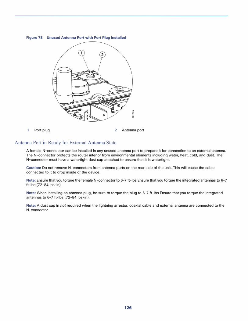
Figure 78 Unused Antenna Port with Port Plug Installed
Antenna Port in Ready for External Antenna State
A female N-connector can be installed in any unused antenna port to prepare it for connection to an external antenna. The N-connector protects the router interior from environmental elements including water, heat, cold, and dust. The N-connector must have a watertight dust cap attached to ensure that it is watertight.
Caution: Do not remove N-connectors from antenna ports on the rear side of the unit. This will cause the cable connected to it to drop inside of the device.
Note: Ensure that you torque the female N-connector to 6–7 ft-lbs Ensure that you torque the integrated antennas to 6–7 ft-lbs (72-84 lbs-in).
Note: When installing an antenna plug, be sure to torque the plug to 6–7 ft-lbs Ensure that you torque the integrated antennas to 6–7 ft-lbs (72-84 lbs-in).
Note: A dust cap in not required when the lightning arrestor, coaxial cable and external antenna are connected to the N-connector.
1 Port plug 2 Antenna port39
2063
1 2
126

Figure 79 Antenna in Ready for External Antenna State with N-Connector Installed
Antenna Port in External Antenna Connected State
An antenna port with an external antenna connected has the following items installed:
N-connector
Lightning arrestor
External antenna cable
External antenna
For information about the lightning arrestor, see the Lightning Arrestor for the Cisco 1240 Connected Grid Router guide on Cisco.com
For detailed instructions for installing antennas and lightning arrestors, see the Connected Grid Antennas Installation Guide on Cisco.com.
Antenna Port NumberingThis section illustrates the antenna port locations on the router. The antenna port numbers should be referenced by installers, support technicians, and other end users when installing, replacing, or troubleshooting the antennas.
1 Antenna port 5 5/8-24 UNEF-2A threads
2 N-connector 6 5/8-24 UNEF-2A threads
3 Water-tight dust cap 7 5/8-24 UNEF-2B threads
4 5/8-24 UNEF-2B threads
3920
64
1
3
2
45
6
7
127

Antenna Installation Location
Caution: Supported antennas can be installed in any of the router antenna ports, however Cisco recommends that antennas be installed in the locations recommended in the antenna installation guide. Installing antennas in the recommend locations optimizes ease of installation, antenna performance. and antenna cable management.
The recommended location for each antenna depends on several factors, including:
The type and number of modules installed in the router
The type and number of antennas required to support the installed modules
The procedures in the antenna installation guide refer to the port numbers illustrated in this section.
Figure 80 Top of Router—Antenna Port Numbering
128

Figure 81 Bottom of Router—Antenna Port Numbering
Safety InformationRead the information in the antenna installation guide before installing or replacing antennas.
Antenna Technical SpecificationsThis section lists the technical information for the GPS and WiFi antennas:
GPS Antenna Specification, page 130
WiFi Antenna Specification, page 130
For more information about Cisco Connected Grid antennas see the Connected Grid Antennas Installation Guide.
Antenna Port Antenna Type
1 4GLTE/WIMAX auxiliary antenna
2 4GLTE/WIMAX main antenna
3 3G/4G main antenna
4 3G/4G auxiliary antenna
5 900 MHz antenna
6 Integrated WiFi antenna (router ships with this antenna installed)
7 -
8 -
5 6
8 7
Front of Router (Door)
3005
65
129

GPS Antenna Specification
WiFi Antenna Specification
Table 24 GPS Antenna Specification
Specification GPS Antenna
Type Active GPS, chassis mounted
Frequency 1575.42 MHz
Height 22.1 mm
Base diameter 50 mm
Maximum gain (dBi) 5
Polarization RHCP
Coaxial cable length 10 in. (25.4 cm)
Coaxial cable type 50 Ohms, double-shielded, LMR-100A
Connector MCX
Environment Outdoor
Temperature range, operational -40 to 185°F (-40 to 85°C)
Temperature range, storage -40 to 185°F (-40 to 85°C)
Table 25 WiFi Antenna Specification
Specification WiFi Antenna
Type Monopole
Environment Outdoor
Height 3.2 in. (8.13 cm)
Width (maximum, at base) 1.75 in. (4.45 cm)
Operating frequency range 806-960 MHz
1710-2170 MHz
2300-2700MHz
Characteristic impedance 50 ohm
VSWR Nominal (Maximum)806–960 MHz (2.5:1)
1710–2170 MHz (2.3:1)
2300–2700 MHz (2.2:1)
Peak gain Nominal (Maximum)806–960 MHz (2.5 dBi +/- 1.0 dB)
1710–2170 MHz (1.0 dBi +/- 1.0 dB)
2300–2500 MHz (1.0 dBi +/- 1.0 dB)
2500–2700 MHz (2.5 dBi +/- 1.2 dB)
130

Polarization Linear
Vertical
Coaxial cable length 8 inches (20.3 cm), LMR-100A
Connector MCX
Temperature range, operational -40 to 185°F (-40 to 85°C)
Temperature range, storage -40 to 185°F (-40 to 85°C)
Maximum input power 10 W (avg.)
Compliance RoHS
Table 25 WiFi Antenna Specification (continued)
Specification WiFi Antenna
131

132