antenna tower positioning system - mdl technologies 7 1.0 introduction the ets-lindgren model 1052...
TRANSCRIPT

Model 1052
Antenna Tower
Positioning System
User Manual
(Antenna not included)

ii |
ETS-Lindgren L.P. reserves the right to make changes to any product described
herein in order to improve function, design, or for any other reason. Nothing
contained herein shall constitute ETS-Lindgren L.P. assuming any liability
whatsoever arising out of the application or use of any product or circuit
described herein. ETS-Lindgren L.P. does not convey any license under its
patent rights or the rights of others.
© Copyright 1990–2010 by ETS-Lindgren L.P. All Rights Reserved. No part
of this document may be copied by any means without written permission
from ETS-Lindgren L.P.
Trademarks used in this document: The ETS-Lindgren logo is a trademark of
ETS-Lindgren L.P.
Revision Record
MANUAL,MODEL 1052 | Part #399163, Rev. D
Revision Description Date
A Initial Release June, 1990
B Updated assembly instructions;
half-size format
April, 2008
C Updated assembly instructions and
illustrations
July, 2008
D Added Using Guy Ropes content;
updated Specifications
March, 2010

| iii
Table of Contents
Notes, Cautions, and Warnings ................................................ v
1.0 Introduction .......................................................................... 7
ETS-Lindgren Product Information Bulletin ................................................... 7
2.0 Maintenance ......................................................................... 9
Annual Calibration ......................................................................................... 9
Service Procedures ....................................................................................... 9
3.0 Specifications ..................................................................... 11
Load Capacity .............................................................................................. 11
Physical Specifications ................................................................................ 11
4.0 Assembly Instructions ...................................................... 13
5.0 Operation ............................................................................ 21
Before You Begin ......................................................................................... 21
Using Guy Ropes ......................................................................................... 22
Appendix A: Warranty ............................................................. 23

iv |
This page intentionally left blank.

| v
Notes, Cautions, and Warnings
Note: Denotes helpful information intended to
provide tips for better use of the product.
Caution: Denotes a hazard. Failure to follow
instructions could result in minor personal injury
and/or property damage. Included text gives proper
procedures.
Warning: Denotes a hazard. Failure to follow
instructions could result in SEVERE personal injury
and/or property damage. Included text gives proper
procedures.
See the ETS-Lindgren Product Information Bulletin for safety,
regulatory, and other product marking information.

vi |
This page intentionally left blank.

| 7
1.0 Introduction
The ETS-Lindgren Model 1052
Antenna Tower Positioning
System is designed for portable
antenna positioning in EMC
compliance testing.
A hand winch and pulley drive
system elevates the antenna
carrier from one to four meters.
Maximum carrier load capacity
is 11.3 kg (24.91 lb) on the tip of
the cross boom. For loads
measured on the center of the
cross boom, the capacity is
22.7 kg (50.04 lb).
The mast is constructed of a high density fiberglass reinforced polymer with a
high degree of immunity to structural deterioration from environmental elements.
The base is an aluminum four-leg design for maximum support and portability.
The design of the Model 1052 allows easy assembly and usage.
ETS-Lindgren Product Information Bulletin
See the ETS-Lindgren Product Information Bulletin included with your shipment
for the following:
Warranty information
Safety, regulatory, and other product marking information
Steps to receive your shipment
Steps to return a component for service
ETS-Lindgren calibration service
ETS-Lindgren contact information

8 |
This page intentionally left blank.
| 9
2.0 Maintenance
Before performing any maintenance, follow
the safety information in the ETS-Lindgren
Product Information Bulletin included with
your shipment.
Maintenance of the Model 1052 is limited to
external components such as cables or
connectors.
Routinely inspect the winch rope for wear.
If wear or any deterioration is found,
replace the rope immediately.
If you have any questions concerning
maintenance, contact ETS-Lindgren
Customer Service.
Annual Calibration
See the Product Information Bulletin included with your shipment for information
on ETS-Lindgren calibration services.
Service Procedures
For the steps to return a system or system component to ETS-Lindgren for
service, see the Product Information Bulletin included with your shipment.
WARRANTY

10 |
This page intentionally left blank.

| 11
3.0 Specifications
Load Capacity
Maximum Carrier Load Capacity
On Tip of Cross Boom: 11.3 kg (24.91 lb)
On Center of Cross Boom: 22.7 kg (50.04 lb)
Physical Specifications
Nominal Height: 4 m (13.12 ft)
Overall Height: 7 m (22.96 ft)
Weight: 34.47 kg (76.0 lb)

12 |
This page intentionally left blank.

| 13
4.0 Assembly Instructions
Before connecting any components, follow the
safety information in the ETS-Lindgren
Product Information Bulletin included with your
shipment.
Prior to assembly and operation of the Model 1052 Antenna Tower
Positioning System, read Operation on page 21.
1. Attach lower mast section to base assembly—Install the lower mast onto
the center post of the base assembly, aligning the markers.

14 |
The rope clamp is located on a wire (as shown) for shipping purposes
only. During step 6 of the assembly instructions you will move the rope
clamp to the rope.
2. Attach winch assembly to lower mast section
Install the winch assembly onto the lower mast with the crank side of the
winch aligned with the marker on mast. Place the crank on either side of
the mast, as desired.

| 15
Secure winch with winch lock pin by sliding the pin through the winch and
mast.

16 |
3. Slide carrier assembly onto lower mast.
Carefully place the mast and base assembly onto the side.
Slide the carrier assembly over the lower mast.
The carrier assembly and boom collar/brackets should face away from the
winch. The long side of the carrier assembly should face upward.

| 17
4. Install upper mast section—With
the pulley at the top, insert the
upper mast into the lower mast, and
align the markers.
5. Thread winch rope from winch,
through pulley, and down the
other side to the carrier.
Remove the clevis pin at the top
of the upper mast.
Unwind the winch rope to the top
of mast and place it over the
pulley.
Secure the rope in the pulley
groove with the clevis pin.
18 |
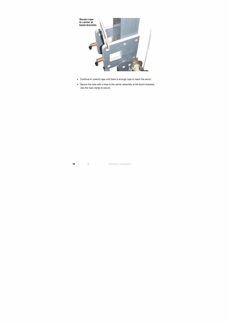
Continue to unwind rope until there is enough rope to reach the winch.
Secure the rope with a loop to the carrier assembly at the boom brackets.
Use the rope clamp to secure.

| 19
6. Move rope clamp from shipping wire to rope.
Remove the four bolts from the rope clamp to separate the two pieces.
About two inches above where the rope is secured at the boom brackets,
place one piece of the rope clamp on each side of the rope.
To clamp the rope, re-attach the two pieces with the four bolts.
7. Attach boom—Insert the boom through the boom brackets on the carrier
with the cable guide oriented towards the back.

20 |
8. Install extension legs.
Position the carrier at the winch assembly.
Raise the entire unit until it is in an upright position, resting on the base.
Install the extension legs into the base with each leg oriented so the
pin hole is nearest to the bottom side of the leg.
Secure each extension leg with a lock pin.
Use thumbscrews to make vertical adjustments to legs.
9. Thread cable through cable guide—Insert the feed cable for the antenna
into the cable guide to reduce stress on the cable and antenna connector.
Mount an antenna to the boom by threading the mounting knobs up through the
holes in the boom and into the mounting receptacle on the antenna.
To install guy ropes, see Using Guy Ropes on page 22.

| 21
5.0 Operation
Before You Begin
Before placing into operation, follow the safety
information in the ETS-Lindgren
Product Information Bulletin included with your
shipment.
Follow these guidelines prior to operating the
Model 1052.
Make sure that the winch is always securely fastened to the mast.
Do not exceed load capacity. See Specifications on page 11 for
maximum load capacity measurements.
Routinely inspect the winch rope for wear. If wear or any deterioration
is found, replace the rope immediately.
Do not overload, kink, or knot the rope.
Do not alter or customize the mast or winch assemblies.
Do not walk under a load that is suspended in the air.
22 |
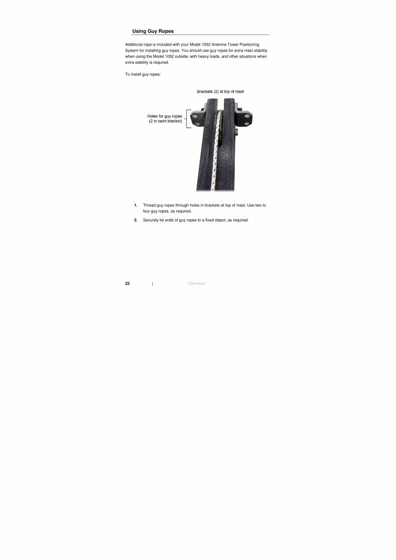
Using Guy Ropes
Additional rope is included with your Model 1052 Antenna Tower Positioning
System for installing guy ropes. You should use guy ropes for extra mast stability
when using the Model 1052 outside, with heavy loads, and other situations when
extra stability is required.
To install guy ropes:
1. Thread guy ropes through holes in brackets at top of mast. Use two to
four guy ropes, as required.
2. Securely tie ends of guy ropes to a fixed object, as required.

| 23
Appendix A: Warranty
See the Product Information Bulletin included with your shipment for
the complete ETS-Lindgren warranty for your Model 1052 Antenna
Tower Positioning System.
DURATION OF WARRANTIES FOR MODEL 1052
All product warranties, except the warranty of title, and all remedies for warranty
failures are limited to two years.
Product Warranted Duration of Warranty Period
Model 1052 Antenna Tower
Positioning System
2 Years