ansys civilfem bridge webinar - caeai.com · ansys civilfem bridge webinar ... —perform what if...
TRANSCRIPT

ANSYS CivilFEM Bridge Webinar
P t R B tt M S C E P EPeter R. Barrett, M.S.C.E., P.E.
© 2009 CAE Associates

ANSYS + CivilFEM
Challenges of Bridge Engineers today:— Increase Construction efficiency— Design and Build to Save Material Costs— Extend the life of existing bridgesg g— Better Empower a shrinking engineering workforce
Solution Solution— Develop more accurate representation of the structural response:
• Nonlinear analysis and incremental construction are ANSYS/CivilFEM strengths
D l t t d l t d i ti— Develop automated analyses to save design time— Perform what if and design optimization tasks to create more effective
use of construction materials
2

CAE Associates – CivilFEM / ANSYS Partner
The world’s biggest and most sophisticated users of engineering simulation choose CAE Associates for consulting services, training and software. e.g. ABB, AREVA, Bechtel-Houston, GE (Nuclear, Energy, Aviation, GRC), Seimens, UTC (Pratt & Whitney, Otis, Sikorsky), AECOM, Westinghouse, Parsons….
Si th ’ i ti i 1981 h i li d i idi Since the company’s inception in 1981, we have specialized in providing solutions to engineering problems using FEA and CFD technology.
3
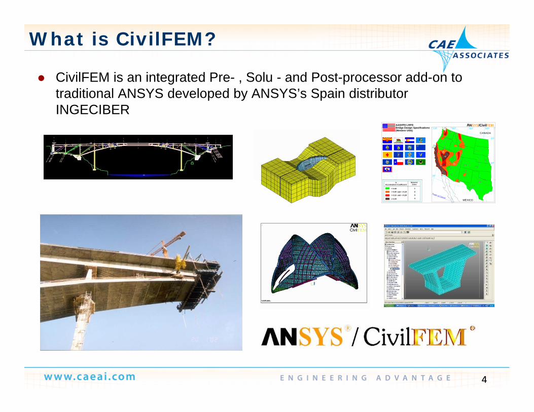
What is CivilFEM?
CivilFEM is an integrated Pre Solu and Post processor add on to CivilFEM is an integrated Pre- , Solu - and Post-processor add-on to traditional ANSYS developed by ANSYS’s Spain distributor INGECIBER
100º110º120º130ºAASHTO LRFDBridge Design Specifications
N /CivilSYS FEM
55
2.5
40
5
15
15
5
8060
50
60
5
5
5
2.5
5
2.5
60
CANADA
100º110º120130
50º
40º
30º
Bridge Design Specifications (Western USA)
Tropic of Cancer
52.5
2.5
MÉXICO
AAcceleration Coefficient
Seismic Zone
1
2
3
4> 0.29
> 0.19 and < 0.29
_> 0.09 and < 0.19
_
< 0.09
_
4

INGECIBER- CivilFEM Developer / ANSYS Partner
Ingeciber S.A. is a CAE company and ANSYS Channel Partner with more than 20 years of experience using and developingwith more than 20 years of experience using and developing CAE Software
Ingeciber’s Quality Assurance System is ISO 9001 certified. g Q y y
ANSYS, Inc. and Ingeciber, S.A. have a long standing OEM Agreement and established a strategic alliance for FEA solutions i h i i d S ld id Cin the construction industry. Some worldwide Customers:
5

ANSYS Today
World’s Largest Simulation CommunityWorld s Largest Simulation Community
>10,000 Total Customers
>125 000 Commercial Seats
>6,000 Total Customers
>60 000 Commercial Seats
>2,000 Total Customers
>10 000 Commercial Seats>125,000 Commercial Seats >140,000 University Seats > 200 Channel Partners > 75 Industry Partners
>60,000 Commercial Seats >70,000 University Seats >20 Channel Partners >80 Industry Partners
>10,000 Commercial Seats
6

ANSYS + CivilFEM
ANSYS + CivilFEM combines the world leading general ANSYS + CivilFEM combines the world leading general purpose structural analysis features of ANSYS (ISO-9001) with high-end civil engineering-specific structural analysis capabilities of CivilFEM (ISO-9001).
7

Current CivilFEM Distributors
8

CAE Associates, Inc.
» One of first 4 ANSYS Channel Partners Since 1985…
» Engineering Co
9
» Engineering Co. Since 1981

CAE Associates – CivilFEM / ANSYS Partner
25 years Structural Thermal and Fluid engineering consulting 25 years Structural, Thermal and Fluid engineering consulting One of the original ANSYS Channel partners The US leader in ANSYS Finite Element Training The US leader in ANSYS Finite Element Training Custom Training of ANSYS and CivilFEM
10
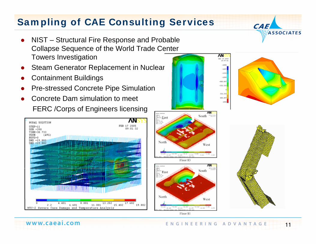
Sampling of CAE Consulting Services
NIST – Structural Fire Response and Probable Collapse Sequence of the World Trade Center Towers Investigation
Steam Generator Replacement in Nuclear C t i t B ildi Containment Buildings
Pre-stressed Concrete Pipe Simulation Concrete Dam simulation to meet
FERC /C f E i li iFERC /Corps of Engineers licensing
11

CAE Associates Senior Technical Staff
Nicholas M. Veikos, Ph.D., President
Peter R. Barrett, M.S.C.E., P.E., Vice President
Michael Bak, Ph.D., Project Manager
P t i k C i h M S M E P j t MPatrick Cunningham, M.S.M.E., Project Manager
Steven Hale, M.S.M.E., Project Manager
James Kosloski, M.S.M.E., Project Manager, , j g
Hsin-Hua Tsuei, Ph.D., CFD Manager
Jonathan Masters, Ph.D., Project Manager
George Bauer, M.S.M.E., Project Manager
Eric Stamper, M.S.M.E., Project Manager
Michael Kuron M S M E Project EngineerMichael Kuron, M.S.M.E., Project Engineer
Lawrence L. Durocher, Ph.D., Director
12
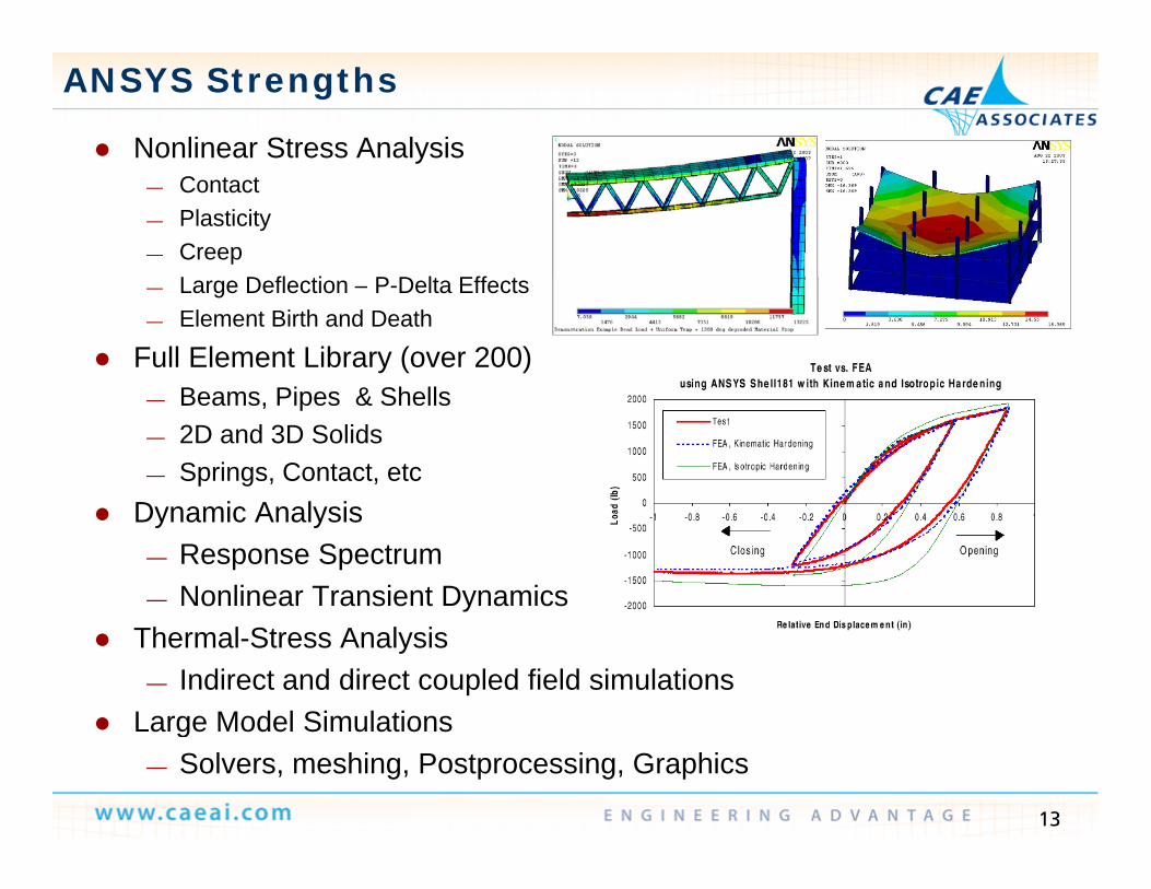
ANSYS Strengths
Nonlinear Stress Analysis— Contact— Plasticity— Creep
L D fl i P D l Eff— Large Deflection – P-Delta Effects— Element Birth and Death
Full Element Library (over 200)B Pi & Sh ll— Beams, Pipes & Shells
— 2D and 3D Solids— Springs, Contact, etc
Dynamic Analysis— Response Spectrum— Nonlinear Transient Dynamics
Thermal-Stress Analysis— Indirect and direct coupled field simulations
Large Model Simulations
13
Large Model Simulations— Solvers, meshing, Postprocessing, Graphics

CivilFEM Strengths
CivilFEM Capabilities CivilFEM Capabilities— Entire suite of ANSYS capabilities including nonlinear analysis
and dynamicsB ilt i M t i l M d l d C d Ch ki— Built-in Material Models and Code Checking
Industry Specific CivilFEM Modules— Nonlinear Bridge Simulation— Pre-stressed Concrete— Geotechnical Applications including tunnelling
14
Geotechnical Applications including tunnelling— Nuclear Applications

CivilFEM & ANSYS
15

CivilFEM –Help
Interactive Online Help Interactive Online Help Examples Manuals Advanced Workshops Training Courses
16

Bridges and N li iti Nonlinearities
Overview

Quote from Bridge Designer"ANSYS has always been a powerful tool in the resolution of advancedstructural problems such as arch buckling evolutive process etc Nowstructural problems, such as arch buckling, evolutive process, etc. Now,with the addition of CivilFEM, it has become a decisive instrument in theentire design and project of bridges such as our "Viaducto del Sil, enPonferrada (León, Spain)".
In the analysis of large bridges you must take into account a lot ofstructural features; different materials, types of section, constructionprocess,... CivilFEM Preprocessor is a definitive help to give ANSYS all thei f ti it dinformation it needs.
Later, CivilFEM Postprocessor allows you to check your model under severalInternational Codes and, both quickly and safely, confirming that thesolution proposed for the bridge is valid.
This whole process eventually concludes in a highly accurate answer to ourclients' requests, with considerable savings in the amount of time spent indeveloping the whole project and with a decisive saving of costs in theconstructed bridge.“Kind regards,Jorge Pérez Armiño
18
A.T.P. Ingeniería, S.L.www.atp-ingenieria.es

Bridge Module Main Features
Utilities for generating common bridge sections and layout design
Bridge layout modelling (in plan and elevation view) Geometric and finite element model generation with g
either Beams or Shells or 3d Solid elements including wizards for
• Suspension bridges• Arch bridges• Cable-Stayed bridges
Load Generation— Overloads— Moving loads (vehicle’s editor)— Utility for Automated Prestressed force input— User loads— Automatic Load combinations
Simulation of construction process
19
p Concrete Creep and Shrinkage

Section Definition
Using the Bridge Section explorer (Slab or Box) Using the Bridge Section explorer (Slab or Box)
20
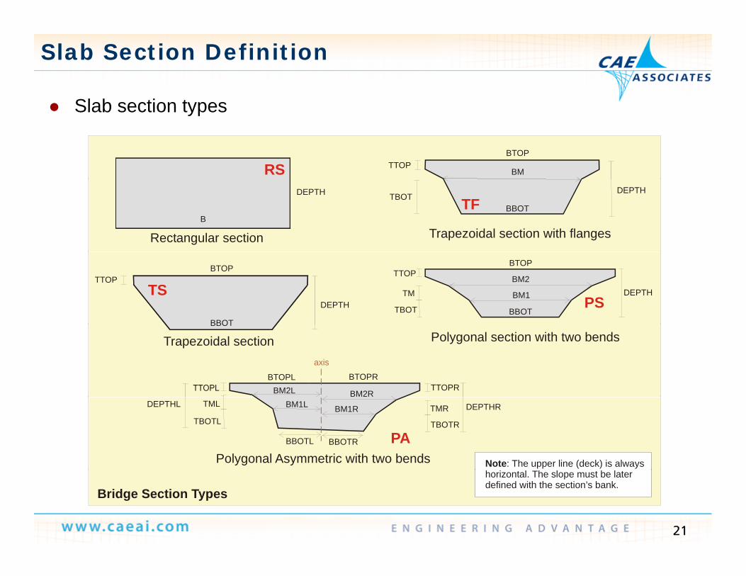
Slab Section Definition
Slab section types
RSBTOP
BMTTOP
Slab section types
Rectangular section Trapezoidal section with flangesB
DEPTH DEPTH
BBOTTBOT TF
BTOP
BBOT
DEPTH
TTOPTS
TBOT BBOT
BM2
BM1
BTOP
DEPTH
TTOP
TMPS
BBOT
Trapezoidal section Polygonal section with two bends
BM2R
BTOPRBTOPLBM2L TTOPR
axis
BBOT
Polygonal Asymmetric with two bends Note: The upper line (deck) is always
BBOTR
BM1RBM1L
BBOTL
DEPTHL
TBOTL
TML
TBOTR
TMR DEPTHR
PA
21
Bridge Section Typeshorizontal. The slope must be laterdefined with the section’s bank.

Slab Section Definition
Slab section definition window General Shape: Slab section definition window – General Shape:
S tiSections are defined by dimensions
22

Slab Section Definition
Holes are defined
Global size Cell dimensions
Holes are defined Mesh divisions are defined Supports are defined (3d Model)
HolesFlange
23

Box Section Definition
Box Section definition window:
Main dimensions are entered here.
After the initial After the initial shape has been created, the geometry g ywill be refined using step-by-step modification.
24

Box Section Definition
Modify Box Section dimensions:
CellSymmetry
Modify Box Section dimensions:
WebFlange
25

Box Section Definition
Modify Box Section dimensions: Modify Box Section dimensions: — Crown
26

Box Section Definition
Box Section window:
Global Size Top div
o Sect o do— Edit Mesh Divisions
Size Top div
Bottom
Web div
Bottom div
27

Box Section Definition
It is important to note that all the cross sections defined must have the psame number of divisions (the same number of sub-elements). If not, the program will not be able to generate a swept mesh of the bridge automatically.
The program will not be able
1
2
123 The program will not be able
to mesh the bridge because the two cross section defined do not have the same number
3
4
5
4
of divisions5
28

Box Section Definition - Script
! Defines a cross section in a box cross-section bridge.! Main Menu > CIVIL Preprocessor > Bridges Prep > Bridge Sections > Box!~BRSBOX, NSEC, MAT, NCEL, DEPTH, WDTCEL, THTOP, THBOT, THWEB, LFL~BRSBOX, 1, 1, 1, 2.5, 6.00, 0.25, 0.2, 0.5, 2.5 ~BRSMDF,1,NAME,,,Section 3! Main Menu > CIVIL Preprocessor > Bridges Prep > Bridge Sections > Modify!~BRSMDF,ICSEC, Lab1, Lab2, Lab3, VALUE, IDX1, IDX2, IDX3 ~BRSMDF, 1, BOX, KSYM, , -1!A=0.75/SQRT(2.50**2+0.75**2) ~BRSMDF,1,BOX,WEB,SLOPE,-A,0,0,0 ~BRSMDF,1,BOX,WEB,RATS,0.25,0,1,0~BRSMDF 1 BOX WEB SLPS 0 1 0 1 0BRSMDF,1,BOX,WEB,SLPS,0.1,0,1,0~BRSMDF,1,BOX,WEB,RATB,0.12,0,1,0~BRSMDF,1,BOX,WEB,SLPB,0.75,0,1,0~BRSMDF,1,BOX,WEB,RATB,0.2,0,3,0
BRSMDF 1 BOX WEB SLPB 0 49 0 3 0~BRSMDF,1,BOX,WEB,SLPB,0.49,0,3,0~BRSMDF,1,BOX,FLANGE,THICK,0.15,0,0,0 ~BRSMDF,1,BOX,WEB,RATS,1 ,1,1,0 ~BRSMDF,1,BOX,WEB,SLPS,0.1,1,1,0
29

Layout Definition
Bridge layout is performed as follows: Bridge layout is performed as follows:— Define Angle units (only for the layout)— Definition of the mileage points that represent the structure
axisaxis• Typically read from a file
~BRINIP,1,0,0,0,0,0 ! Defines the MP and Ansys direction ! from which the bridge model is generated
~BRADDPL,99.5,153.5 ! bridge layout in plan view ~BRADDEL,99.5,153.5 ! bridge layout in elevation view~BRSKTCH,5 ! Plots the bridge axis (MP’s path)
! Example~BRINIP,1,~BRADDPL, 90,120, 0, 0~BRADDPL, ,170, 0,-200~BRADDEL, 90,170, 0, 0
— Definition of plan and elevation layout
30

~BRADDPL MP1 MP2 Ri Rf ang
Layout in Plan View
~BRADDPL, MP1, MP2, Ri, Rf, ang
MP: initial and final “mileage point” R: initial and final curvature radiusR: initial and final curvature radius ANG: angle with respect to previous
sectionsection.
31

Layout in Plan View
Plan view parameter definition
Case 1: Straight stretch, If a radio is infinite the field is not introduced, or the value zero is introduced.
Case 2: Circumference, If Ri = Rf Null:0
Case 3: Clothoid (double
32
Case 3: Clothoid (doublespiral spline ), If Ri Rf

BRADDEL MP1 MP2 ii if
Layout in Elevation View
~BRADDEL, MP1, MP2, ii, if
MP: initial and final mileage point” point
II, IF: Slopes in % of the initial initial
And final MP of the stretch
ANG: angle respect to the previous stretch
33

Layout in Elevation View
Elevation view parameter definition
If II = IF the stretch, in elevation view, is a straight line then CivilFEM will fit a parabola
34
straight line then CivilFEM will fit a parabola.
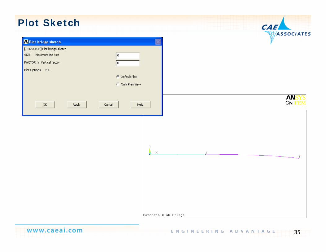
Plot Sketch
35
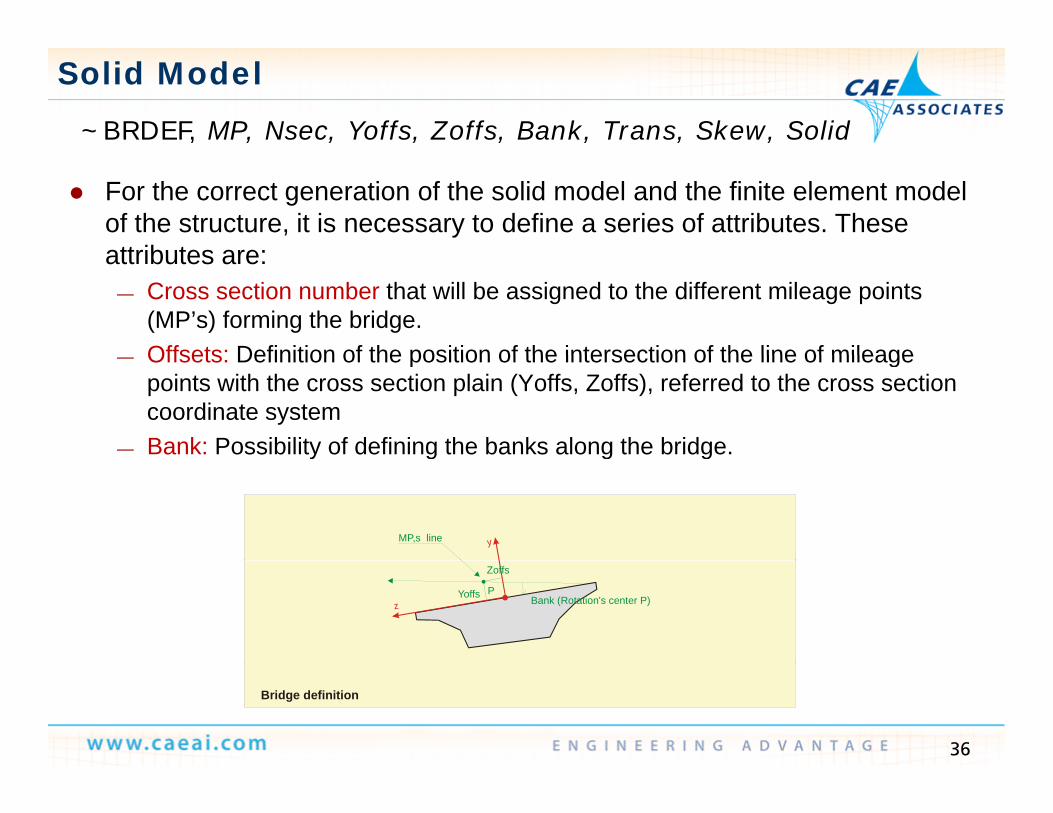
~BRDEF, MP, Nsec, Yoffs, Zoffs, Bank, Trans, Skew, Solid
Solid Model
For the correct generation of the solid model and the finite element model of the structure, it is necessary to define a series of attributes. These attributes are:attributes are:
— Cross section number that will be assigned to the different mileage points (MP’s) forming the bridge. Offsets: Definition of the position of the intersection of the line of mileage— Offsets: Definition of the position of the intersection of the line of mileage points with the cross section plain (Yoffs, Zoffs), referred to the cross section coordinate system
— Bank: Possibility of defining the banks along the bridge.
yMP,s line
y g g g
z
Zoffs
Yoffs Bank (Rotation's center P)P
36
Bridge definition

Solid Model
Skew: This capability allows the definition of an offset angle of the cross Skew: This capability allows the definition of an offset angle of the cross section with respect to the road axis.
H ll lid i Thi bili ll h d fi h ll Hollow or solid section: This capability allows the user to define hollow or solid sections for a particular mileage point. Therefore, the user may consider hollow sections or solid section at particular points of the structure (at supports for example) (Only valid for slab cross section)structure (at supports, for example).(Only valid for slab cross-section)
Hollow section (Solid=0 or blank Solid section
According to original contour (Solid0)
37
Cross sections at supports

Solid Model
38

Model Generation
This utility generates the complete geometrical model of the structure as well as the finite element model from the cross sections definition (location, “offsets”, banks, etc)
— It is generated from the defined sections— It utilizes the previously defined layout— It generates the finite element model of either beams, shells
3 d b i k t ti llor 3-d bricks automatically
39

Bridge Wizards
Supported Bridges Supported Bridges— Concrete (with a CivilFEM bridge section)— Steel (with a CivilFEM steel 3D pattern)
Generic (with a CivilFEM generic cross section)— Generic (with a CivilFEM generic cross section)
Cable Stayed Bridges( ith Ci ilFEM b id ti )(with a CivilFEM bridge section)
Arch Bridges(with a CivilFEM bridge section)
— Beam model— Shell model
40

Bridge Wizards
Bridge Generators windows can generate 3D models for:Bridge Generators windows can generate 3D models for:
Concrete Suspension Bridges( ith Ci ilFEM b id ti )(with a CivilFEM bridge section)
Steel Suspension Bridges Steel Suspension Bridges(with a CivilFEM steel 3D pattern)
G i S i B id Generic Suspension Bridges(with a CivilFEM generic cross section)
Mixed section, two types of section:— Concrete slab over I-section steel beams — Concrete slab over a steel box
41
— Concrete slab over a steel box

Suspension Bridge Generators
Concrete Suspension Bridgesp g
42

Supported Bridge Example
Supported Bridges :— Same parameters as suspension bridges are used, but only bridge deck will be
generated.
Concrete Steel
43

Loads Definition
In the bridge analysis process a great number of load steps In the bridge analysis process, a great number of load steps are automatically generated such that can easily be incorporated into load combinations
— Load types :• Mobile (vehicles, pedestrian, etc.)• Surface loads (structural, traffic, snow, etc.)( )• Prestressing, in any direction.• Self weight
— The loads generate LoadStates (LS) that are grouped in families and
LS 1
e oads ge e ate oadStates ( S) t at a e g ouped a es a dlater become combinations.
S
LS 2
LS 71
Vehicle Load
Family 19 Combination 19
44
LS 71

Loads Definition: Families
A family is a group of load states usually of the same A family is a group of load states, usually of the same topology.
All the load steps belonging to a family are combined into one unique load step according to their natureinto one unique load step according to their nature
The combined family can be later introduced as a starting point in load combinations. Load factor coefficients will be the same for each Load factor coefficients will be the same for each family
45

Loads Generation (Traffic Loads)
Vehicles: Rigid (truck) or flexible (train, adaptable to the path)g ( ) ( p p ) User friendly path definition: road surface and road axis are automatically
detected by the program
46

Loads Definition: Vehicles
Start End
Bridge deckFirst h l
Last vehicle vehicle
positionvehicle
position
It is possible to define when the vehicle movement starts and ends, relative to the bridge geometry.
47

Loads Generation (Prestressing Cables)
Definition of points along the cable’s path (automatic adjustment of the Definition of points along the cable s path (automatic adjustment of the points using splines)
Introduce the tensile force at specific locations in the tendon’s pathA tomatic transfer of the cable action to the str ct re Automatic transfer of the cable action to the structure
P' 1 P'N
P
P
PP
P1
2
k+2k+1
NPk
OP
Rz
MRz
MR Kfz
T1
1
3D spline generation x
RMR
y
x
c.d.g.R
y
Kfx
Kfy
T2
2
48
Transmision of the cable actions to the model

3D Tendon Geometry Editor
It allows the definition and edition of the geometric and strength properties It allows the definition and edition of the geometric and strength properties of all tendons of a structure. The geometry may be shown and edited either graphically or by coordinates.
Tool Bar
Elevation
Object Tree
Elevation View
Info/Edit Window
49
Plan View

Prestressed Forces, Moments & Stresses
Stresses in the support and in the middle of span.
50

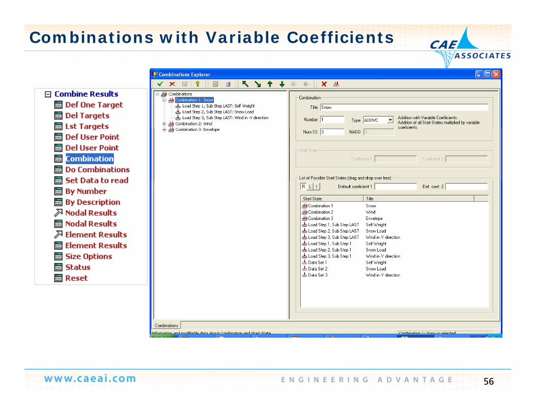
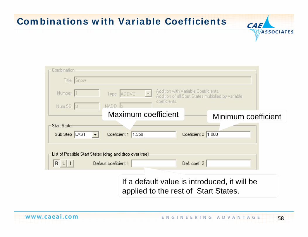
Combinations with Variable Coefficients
Where should the two engines be located for the stress to be maximum at Where should the two engines be located for the stress to be maximum at point P?
? ? ?? ? ?
P
51

Combinations with Variable Coefficients
Mobile loads Mobile loads Combinations with variable coefficients (favorable/unfavorable) Actions in different directions (wind, earthquakes, …) Combinations according to codes logic
52

Combinations with Variable Coefficientsm
ost
e m
ost
e 1
ne2
Permanent actions (Gk)
ed in
the
msi
tion
ated
in t
hepo
siti
on
Virt
ual l
ane
Virt
ual l
an
Bord
er
Bord
er
Bord
er
( k)Self weight Dead load of 20 kN/m
Road traffic actions (Qk)
0kN
loca
tevo
rabl
e po
s
200k
N lo
cafa
vora
ble
pV V Vehicles (Double-axis)2x300 kN in virtual lane 12x200 kN in virtual lane 2
U if l di t ib t d l d
2x30
unfa
v
2x unf Uniformly distributed loads
9.0 kN/m2 in virtual lane 12.5 kN/m2 in virtual lane 22 5 kN/m2 in the other areas
Target:• Maximum MZ
2.5 kN/m in the other areas
53
Maximum MZ• Minimum MZ

Combinations with Variable Coefficients
Eurocode No 1: Permanent and transient situations (simplified) Eurocode No.1: Permanent and transient situations (simplified)
Permanent actions Variable actionsThe program will select
kQkG QG The program will select the coefficients to apply for each target and element.
Safety factorSafety factor y
for variable actions:
Q = 0 if it is favorable
y
for permanent actions:
G = 1.00 if it is favorable
Q = 1.00 if it is unfavorableG = 1.35 if it is unfavorable
54

Combinations with Variable Coefficients
Combination Rules are logic relations between Start States Combination Rules are logic relations between Start States. Each combination rule has its own Start States A combination rule may have any number of Start States (up to a
ma im m of 1 000 000)maximum of 1,000,000) The result of the combination is called a combined result Combination rules can be nested That means that the combined result of the combination i can be a start
state for the combinations i+1, i+2, …, n, and combined results of combination i+1 may be a start state for combinations i+2, i+3, …, n
...Q ψ γQ γG γG γ E Windk, Wind0, WindQ,Live k,Live Q,Dead k,Dead G,Gravity k,Gravity G,
55
Combination RuleCombined result Start State
Combinations with Variable Coefficients
56

Combinations with Variable Coefficients
Define the type of combination and the number of Start States Define the type of combination and the number of Start States— Before starting with calculations, you must define all the combination rules and
targets.
Combination name
Combination number
Combination name
Type of combinationNumber of Start States included in this combination rule
57
this combination rule
Combinations with Variable Coefficients
Maximum coefficient Minimum coefficient
If a default value is introduced, it will be applied to the rest of Start States.
58
applied to the rest of Start States.

Code Checking Results
.011637
.039639
.067641
.095642
.123644
.151646
.179647207649
PHASE 1:AXIAL +BENDING CHECKING
.207649
.235651
.263652
X
Y
Z
59
CivilFEM Creep and Shrinkage
Shrinkage Shrinkage— Time dependent deformation without external loads, due to the concrete
hardening. Creep Creep
— Time dependent deformation under the influence of stress
Can cause displacement and deformations that can affect the distribution Can cause displacement and deformations that can affect the distribution of stresses, the reaction forces and the pre-stressing forces that act on the structure.
60

CivilFEM Creep and Shrinkage
)()()( ttt shcrelt (t, )o Strain due to creep only appears
after loading the structure
(t, ) CREEPoCRStrain due to shrinkageappears at the initial time
Elastic strain is produced, instantanously,at the moment the load is applied
(t)e
(t)SH
ELASTIC
SHRINKAGE
t,o t
2
F(t)
0
0
61
Strain components
t,o0

CivilFEM Creep and Shrinkage
Assumption: Assumption: — Linearity: the creep deformation is proportional to the stresses
(t, )
(t,0)
(t, )1
CR
CR
CR
(0)CR
( )1CR
*
*
)( t (t, )2
1CR
CR
( )2CR*
),(·)(),(28,
0 tE
ttc
ccr
t, 1 2
Creep variation with time and with the load application age
The validity of this assumption is experimentally confirmed for initial stresses below 40% of the strength of concrete.
62

CivilFEM Creep and Shrinkage
Assumption: (t, )CR
(t, )1CRI
(t, )2CRII
CR
(t, )CR
CR
Assumption:— Principle of superposition: the
deformation due to creep at time t caused by a stress
t, 1 2t,
t t
o o
yincrement applied at time is independent from any stress increment that takes place before or after time t,1 t,2
T I II
(t, )CR (t, )CR
before or after time
Therefore, the deformations due to creep are addable
1 t,
F FT I
CR CR CR
1 t,
CR CRT I
CR CRT I
CRII
due to creep are addable
t,1 2
o
o
t,1 2
o
Superposition principle
63
p p p p

CivilFEM Creep and Shrinkage
64

CivilFEM Creep and Shrinkage
Shrinkage in CivilFEM is computed from the shrinkage strain curves defined in the concrete material properties.
Curves are calculated from the available codes in CivilFEM— Curves are calculated from the available codes in CivilFEM— Curves can be defined by the user point-by-point.
Sh i k t i ill b t d i ll t i l ith th h i k Shrinkage strains will be computed in all materials with the shrinkage option activated.
— They are introduced in the model by temperature increments and calculated from the thermal strains and the thermal expansion coefficient of the materialfrom the thermal strains and the thermal expansion coefficient of the material.
— Since shrinkage strains are related to thermal strains, temperature increments must not be applied to elements that are associated to materials with the shrinkage option activated.with the shrinkage option activated.
65

CivilFEM Creep and Shrinkage
For a correct evaluation of time-dependent properties ANSYS time For a correct evaluation of time-dependent properties, ANSYS time defined with command TIME, must coincide with active time of CivilFEMdefined with command ~ACTTIME.
All the structural elements of ANSYS support the modeling of concrete shrinkage with CivilFEM. Exceptions:
• All the PIPE elements• All the PIPE elements• SHELL91, SHELL181, SOLID191• SHELL99 and SOLID46 elements can only be used with KEYOPT(2) = 0 or 1
66

CivilFEM Creep and Shrinkage
CivilFEM uses a standard step-by-step method to solve this integral: CivilFEM uses a standard step-by-step method to solve this integral:
I h b h d h i i di id d i i f i l I h— In the step by step method the time is divided into a series of intervals. In each intervals the equilibrium and compatibility conditions of the structure are satisfied. Strain is computed as follows:
t
cccrel d
Et
Ett
028,
)(·),()(
1)()(
— The solution procedure of CivilFEM employs a non linear calculation with automatic time discretization: the time steps, corresponding to ‘load steps’ and ‘substeps’, are chosen to follow the evolution of loads and model geometry.
k
ii
c
ik
ick t
Ett
tEt
1 28,
)(·),()(
1)(
67

CivilFEM Creep and Shrinkage
Strain increments produced by creep are computed from the creep Strain increments produced by creep are computed from the creep coefficients defined in the material properties and from the stress increments produced during the steps of time discretization:
i
o
Variable action discretization
i t,o
Variable action discretization
)()(·),()()()( 11 kcr
k
iik
kcrkcrkcr ttttttt
68
)()()()()( 11 28,
1
kcri
ic
kcrkcrkcr E

CivilFEM Creep and Shrinkage
These creep strains are introduced in the model using ANSYS Creep— These creep strains are introduced in the model using ANSYS Creep (subroutine UserCreep is programmed for this case, which uses an implicit time integration algorithm).
— It is also possible to take into account an aging coefficient. In this case creep strains are computed as follows:
k
ii
ikik
kkcr t
Ettttt
Ettt
11
1 )(·),(·),()(),()(
— t1 is the time of the application of the first load— If the value of the aging coefficient is not specified, the program uses:
i cc EE 1 28,28,
5.0
5.0
1),(
i
iik t
ttt
— Like in case of shrinkage, for a correct evaluation of time-dependent properties, ANSYS time defined with command TIME, must coincide with
ti ti f Ci ilFEM d fi d ith d ACTTIME
69
active time of CivilFEM defined with command ~ACTTIME.

CivilFEM Creep – Effective Modulus Method
This method consists using a elasticity modulus called effective modulus which— This method consists using a elasticity modulus called effective modulus which takes into account the additional strain caused by phenomenon of creep
— The effective modulus is calculated by the following expression:The effective modulus is calculated by the following expression:
,1
,.
tE
EtE
x
xeffcr
,28
1 tEx
— The concrete age at the moment of the load application is calculated as the difference between the load application time, TAppLoad and the material activation time, Tact.
TActTAppLoad
70

CivilFEM Creep – Effective Modulus Method
Thi i lifi d th d d l l d t f h ti t b This simplified method needs only one load step for each time to be solved, so this method is much faster than the step by step method.
Under this method, the creep strain only depends on the current state of stresses that’s why it’s independent of the previous load history. This method provides accurate results for concrete stresses almost constant in titime.
This method is based on the substitution of the material elasticity modulus by an effective modulus so it isn’t possible to determine the creep strain independent to the elastic strain so the final elastic strain will be the combination of these.
71

CivilFEM Creep and Shrinkage
Element types that are supported in CivilFEM to model concrete creep: Element types that are supported in CivilFEM to model concrete creep: Step by step method:
— Beam: LINK180, BEAM188, BEAM189Sh ll SHELL181— Shell: SHELL181
— 2D Solid: PLANE182, PLANE183— 3D Solid: SOLID185, SOLID186, SOLID187
Eff ti d l th d Effective modules method:— All the ANSYS structural elements.
Element types that are supported in CivilFEM to model concrete Shrinkage:
— All the ANSYS structural elements except:• All pipe elements.• SHELL 91, SHELL 181, SOLID 191.• It can only be used on SHELL 99 and SOLID 46 elements if KEYOPT (2)=0 or 1.
72

Creep and Shrinkage Time Stepping
~CFMP,1,LIB,CONCRETE,EC2,C16/20 ! ConcreteCFMP 1 CONCR KCREEP 1 ! C b St B St M th d~CFMP,1,CONCR,KCREEP,,1 ! Creep by Step By Step Method
~CFMP,1,CONCR,KEYCT,,0~CFMP,1,CONCR,KSHRINK,,1 ,0,0,0 ! by temperatures~CFMP,1,CONCR,AGESRINI,,10 ,0,0,0 ! concrete age when shrinkage
!!!!!!!!!!!!!!!!!!!!!!!!!!!!!!!!!!!!!!!!!!!!!!!!!!!!!!!!!!!!!!!!!!!!!!!!!!!!!!!!!!!!!!!!!!!!!!!!!!!!!!!!!!!!!!!!!!!!!!!!!!!!!!!!!!!!!!!!!!!!!!!!!!!!!!!!!!!!!!!!!!!!!!!!!!!!!!!!!!TIME,10 $ ~ACTTIME,10 ! 10 DaysRATE,ONNSUBST,1SOLVENSUBST 10NSUBST,10,TIME,15 $ ~ACTTIME,15 ! 15 DaysSOLVENSUBST,10,TIME,25 $ ~ACTTIME,25 ! 25 Days, $ , ySOLVETIME,90 $ ~ACTTIME,90 ! 90 DaysSOLVETIME,365 $ ~ACTTIME,365 ! 365 DaysSOLVETIME,1000 $ ~ACTTIME,1000 ! 1000 DaysSOLVETIME,10000 $ ~ACTTIME,10000 ! 10000 DaysSOLVE
73
SOLVE

NON- INCREMENTAL ANALYSIS:
Construction Sequence (Curing) Analysis
S l
Concrete
The beam is built by phases, but the supports will not be taken out
Steel
INCREMENTAL S S
The beam is built by phases, but the supports will not be taken out until concrete has gained resistance.
ConcreteINCREMENTAL ANALYSIS:
Steel
Concrete
First the steel beam is placed and then the concrete, without resistance, will b d th t l t t
Steel
74
be poured on the steel structure.

Cable Stayed Bridge Wizard
Nonlinear Construction Process Analysis: Nonlinear Construction Process Analysis:
YX
Y
XY
Z
XZ
XZ
MN
MX
XY
Z
75

Cable Stayed Bridge Wizard
Nonlinear Construction Process Analysis: Nonlinear Construction Process Analysis:
76

Cable Stayed Bridge Wizard
Nonlinear Construction Process Analysis: Nonlinear Construction Process Analysis:
— ~CPDEF,1,3 ! 3 Phases— ! Phase 1
CPSTDEF 1 TIME 0Geometry
— ~CPSTDEF,1,TIME,0— ~CPSTDEF,1,SS,6,14,,0— ~CPSTDEF,1,SS,1,6— ~CPSTDEF,1,TENDON,1,10 Phases
40 m 40 m50 m
— ~CPSTDEF,1,TENDON,11,30,,0— ! Phase 2— ~CPSTDEF,2,TIME,12 ! 12 days— ~CPSTDEF,2,SS,1,11 Cross Sections
Li i i Li i i Li i i
50 m 30 m50 m
Phase 1 Phase 2 Phase 3
Section 1
— ~CPSTDEF,2,TENDON,1,20— ~CPSTDEF,2,TENDON,21,30,,0— ! Phase 3— ~CPSTDEF,3,TIME,24 ! 24 days 8 m 8 m12 m 12 m 8 m 8 m12 m 12 m10 m 10 m15 m 15 m
Section 2 Section 2 Section 2 Section 2Section 1
Linear transition
Section 1
Linear transition
Section 1
Linear transition
Section 2
, , , y— ~CPSTDEF,3,SS,1,14— ~CPSTDEF,3,TENDON,1,30
77

Postprocess Results
-.161E+ 08-.985E+ 07-.361E+ 07.263E+ 07.887E+ 07.151E+ 08214E+ 08
PHASE 1:BENDING MOMENT MZ -.228E+ 08
-.152E+ 08756E+ 07
PHASE 2:BENDING MOMENT MZ
X
Y
Z
.401E+ 08
.214E+ 08
.276E+ 08
.338E+ 08-.756E+ 07.765E+ 07.152E+ 08.229E+ 08.305E+ 08.381E+ 08.457E+ 08
BENDING MOMENT MZ
X
Y
Z
-.220E+ 08-.143E+ 08-.665E+ 07.101E+ 07.867E+ 07.163E+ 08
PHASE 3:BENDING MOMENT MZ
X
Y
Z
.163E 08
.240E+ 08
.316E+ 08
.393E+ 08
.470E+ 08
78
XZ

Case Study: Sil River Bridge
79

Case Study: Sil River Bridge
80

Case Study: Sil River Bridge
81