ansoft electronic design automation - cad-it aac/slides/ansoft_desmond.pdf · ansoft electronic...
TRANSCRIPT

© 2008 Ansoft, LLC All rights reserved. Ansoft, LLC Proprietary
Ansoft Electronic Design
Automation
Desmond Tan
Technical Manager
ANSOFT, LLC.
© 2008 Ansoft, LLC All rights reserved. Ansoft, LLC Proprietary
Ansoft Products And Technology
�Ansoft provides state-of-the-art electronic design solution for engineers to face the design challenge in the next generation products and applications from DC to Daylight.
�The products combine the power of software automation with the intuitive engineering know-
how of the designer, so they can auto-interactively evaluate, design and optimize high-performance with all stream electronic design ranging from signal and power integrity, RF/microwave and communication system, and electromechanical system.

© 2008 Ansoft, LLC All rights reserved. Ansoft, LLC Proprietary
Markets
RF & Microwave
IC Design & VerificationSignal & Power Integrity
FEA
sourceA1
sourceA2
sourceB1
sourceB2
sourceC1
sourceC2
Magnet01
Magnet02
Name Value
FEA1.FEA_STEPS
SIMPARAM1.RunTime [s] 26.41k
SIMPARAM1.TotalIterations 34.51k
SIMPARAM1.TotalSteps 6.00k
ω+
ICA:
+
ΦGAIN
CONST
CONST
EQUBL
EQUBL
EQUBL
1500 rpm
LL:=922u
RA:=2.991
ANGRAD
57.3
-60+PWM_PER
-30+PWM_PER
QS1
QS2
QS3
VAL[0] := mod( INPUT[0] ,INPUT[1] )
PWM_T:=60
I_TARG:=9
I_HYST:=0.2
Q1
Q2
Q3 Q5
Q4 Q6
400 V
THRES := PWM_T
EQUBL
CONST
QS4
-90+PWM_PER
EQUBL
CONST
QS5
-120+PWM_PER
EQUBL
CONST
QS6
-150+PWM_PER
RA Ohm LL H
LDUM:=10m
0
8.50
5.00
0 30.00m20.00m
Q1.CTRL + 7.50
Q2.CTRL + 6.00
Q3.CTRL + 4.50
Q4.CTRL + 3.00
Q5.CTRL + 1.50
Q6.CTRL
-10.30
10.00
0
0 30.00m20.00m
LA.I [A]
LB.I [A]
LC.I [A]PWM_PER:=180
INPUT[1] := PWM_PER
INPUT := -LB.I
LC.I
-LA.I
LB.I
-LC.I
LA.I
THRES1 := I_TARG - I_HYST
THRES2 := I_TARG + I_HYSTVAL1 := 1
VAL2 := 0Y0 := 1
-14.50
7.80
0
0 30.00m20.00m
Torque Output
-30.00k
302.00k
200.00k
0 30.00m20.00m
FEA Outputs
FEA1.WIRELOSS
FEA1.CORELOSS
FEA1.IsourceA
FEA1.VsourceA
FEA1.EIsourceA
FEA1.FLUXsourceA
FEA1.IsourceB
FEA1.VsourceB
FEA1.EIsourceB
FEA1.FLUXsourceB
FEA1.IsourceC
FEA1.VsourceC
FEA1.EIsourceC
FEA1.FLUXsourceC
FEA1.PHI
FEA1.OMEGA
0
8.50
5.00
0 30.00m20.00m
QS1.VAL + 7.50
QS2.VAL + 6.00
QS3.VAL + 4.50
QS4.VAL + 3.00
QS5.VAL + 1.50
QS6.VAL
Electromechanical Systems

© 2008 Ansoft, LLC All rights reserved. Ansoft, LLC Proprietary
Maxwell’s Equation
Electrical engineering is largely derived from Maxwell’s equations
∇×E=−∂B
∂t
∇×H=J+∂D
∂t
∇• D=ρ
∇ B=0•

© 2008 Ansoft, LLC All rights reserved. Ansoft, LLC Proprietary
MARGINFOR
ERROR
Competition
Cost Constraints
Lawsuits/Warranty
Product Innovation
Customer Expectations
Energy Availability
Time to Market
Product Life Cycle
Skilled Labor
Increasing Demands on Engineering
© 2008 Ansoft, LLC All rights reserved. Ansoft, LLC Proprietary
Traditional EDA Shortcomings
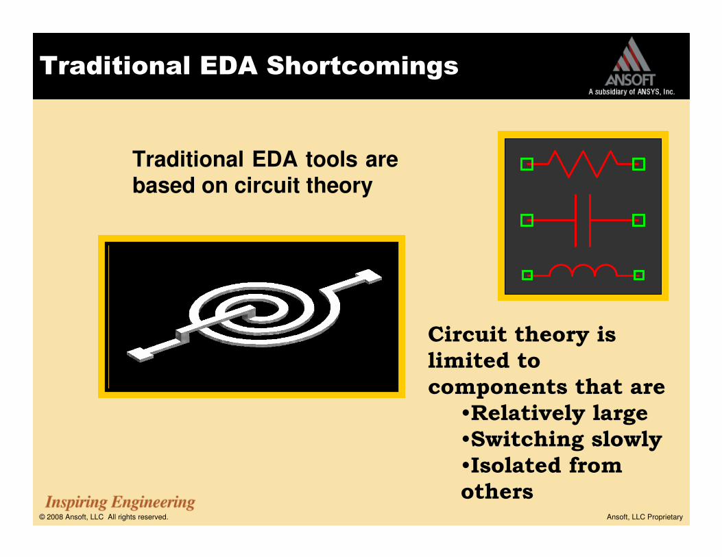
Traditional EDA tools are based on circuit theory
Circuit theory is
limited to
components that are
•Relatively large
•Switching slowly
•Isolated from
others

© 2008 Ansoft, LLC All rights reserved. Ansoft, LLC Proprietary
Real Lofe

© 2008 Ansoft, LLC All rights reserved. Ansoft, LLC Proprietary
Physics-Based Modeling
Frequency-dependent,
full-wave effects
described via
scattering parameters
0.00 5.00 10.00 15.00 20.00 25.00 30.00 35.00 40.00Freq [GHz]
-50.00
-40.00
-30.00
-20.00
-10.00
0.00
Y1
Ansoft Corporation MHC0S-params
Curve Info
dB(St(1a,1a))20GHz : DC_20GHz
dB(St(2a,1a))20GHz : DC_20GHz
0.00 5.00 10.00 15.00 20.00 25.00 30.00 35.00 40.00Freq [GHz]
0.60
0.65
0.70
0.75
0.80
0.85
0.90
0.95
L_n
h
0.00
5.00
10.00
15.00
20.00
25.00
30.00
Q
Ansoft Corporation MHC0Inductance, Q factor
Curve Info
L_nh20GHz : DC_20GHz
Q20GHz : DC_20GHz

© 2008 Ansoft, LLC All rights reserved. Ansoft, LLC Proprietary
Automatic Adaptive Meshing
© 2008 Ansoft, LLC All rights reserved. Ansoft, LLC Proprietary
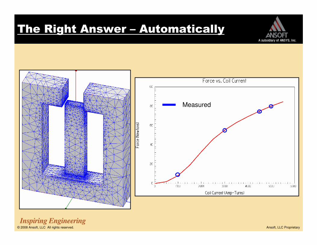
The Right Answer – Automatically
Measured

© 2008 Ansoft, LLC All rights reserved. Ansoft, LLC Proprietary
Ansoft EM Market Focus
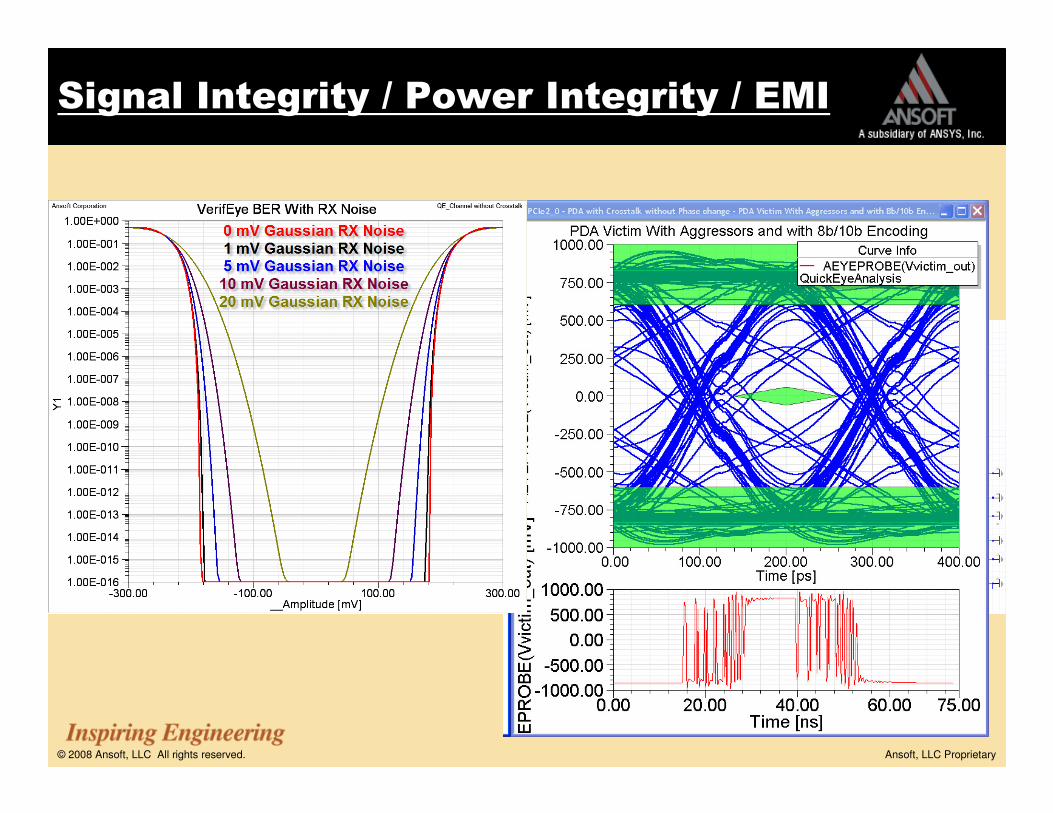
�Signal Integrity / Power Integrity / EMI
�High Frequency Applications – RF / Microwave /
Communication System
�Electromechanical System

© 2008 Ansoft, LLC All rights reserved. Ansoft, LLC Proprietary
Wireless & Wired Communication
Integrated RF/Analog/Digital

© 2008 Ansoft, LLC All rights reserved. Ansoft, LLC Proprietary
Wired CommunicationFast Data Rates, More Loss, Smaller Signal Levels
Reference Maxim Note HFDN-27.0 (Rev. 0, 09/03)
Tx +
-
+
-
Rcvpath +
-
+
-
Clean, open, logical 1 & 0 at launch from transmitter
Smeared edges at end of long interconnect.
Logical 1 & 0 can be hard to distinguish at end of long interconnects; (this is often called a “closed eye”)
Fast, sharp, edges at transmitter launch
Small differences inlevels being measured
© 2008 Ansoft, LLC All rights reserved. Ansoft, LLC Proprietary
High Performance Signal Integrity / Power
Integrity / EMI
+
-
+
-
Via Via Via
MS SL SLPackage PackageConnectorBackplane Daughter Card
FB-DIMM
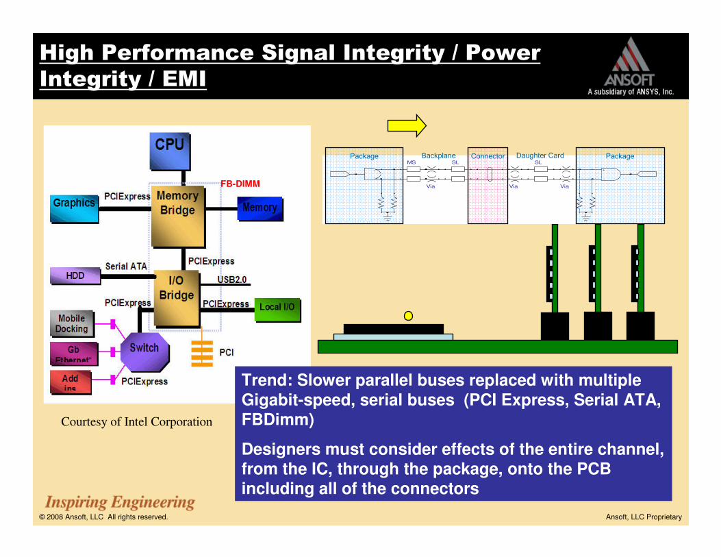
Trend: Slower parallel buses replaced with multiple
Gigabit-speed, serial buses (PCI Express, Serial ATA,
FBDimm)
Designers must consider effects of the entire channel, from the IC, through the package, onto the PCB including all of the connectors
Courtesy of Intel Corporation

© 2008 Ansoft, LLC All rights reserved. Ansoft, LLC Proprietary
Ansoft Signal Integrity / Power Integrity / EMI SolutionAnsoft Signal Integrity / Power Integrity / EMI SolutionAnsoft Signal Integrity / Power Integrity / EMI SolutionAnsoft Signal Integrity / Power Integrity / EMI Solution
2D Extractor
RLGC and Zo parameter extraction for T-lines
SPICE/IBIS/W-element model creation
Q3D Extractor3D Geometry Quasi-static EM analysis
RLC parameter extraction
SPICE/IBIS model creation (Hspice, Spectra…)
HFSS3D Geometry Full-Wave EM analysis
SYZ parameter extraction, propagation constant
SYZ parameters, Port Zo, Fields
EXTRACTION
SIwavePCB/BGA Full-Wave solver for SI/PI analysis
SYZ parameter extraction, Resonances, SSN/SSO
Full-Wave Spice model creation
TPA (Turbo Package Analyzer)BGA package Quasi static EM analysis
RLC parameter extractor
Spice/IBIS model creation
Full Wave SpiceHigh Frequency dependent SPICE models
HSPICE, PSPICE, Spectre RF, Matlab
SIMULATION
Nexxim
High capacity, high speed circuit simulation engine
Transistor level Tx/Rx models included
Native support for HSpice and Spectre
Time and Frequency domain
SPICE/ Measured Data import
Design management tool
System Level Simulator
Planar EM analysis
Cascading models from different Ansoft tools
Designer SI
AnsoftLinks
3rd part CAD interface
PCB CAD : Cadence, Zuken, Mentor, Synopsys
MCAD geometry: 3D CAD, IGES, STEP, Pro/E
Optimetrics
Automatic Optimization
Parametric analysis
Sensitivity Analysis
Statistical Analysis
DESIGN AUTOMATION
DSO (Distributed Solve Option)
Distribute solving of large parametric and
sweep projects across network of computers
Linear Speed Increase with number of computers
Applicable to Q3D and HFSS
Fully Integrated Single EM/Circuit Solution

© 2008 Ansoft, LLC All rights reserved. Ansoft, LLC Proprietary
3D Parasitic Extraction

© 2008 Ansoft, LLC All rights reserved. Ansoft, LLC Proprietary
Circuit & System Simulation
out
pullup
pulldow n
logic_ in
enableout_of _in
out
POWER
GND
logic _in
enableout_of _in
pullup
pulldow n
OUT
PULLUP
PULLDOWN
logic_in
enable
OU T
pu llup
p u l ldo w n
lo g ic_ in
Differential PRBSMicrostrip Circuit
Component
Dynamic Link to
HFSS Via Model
Stripline Circuit
Component
Dynamic Link to
HFSS Stripline
Transition Model
SMA Connector
S-Parameters
BGA Package
S-Parameters

© 2008 Ansoft, LLC All rights reserved. Ansoft, LLC Proprietary
Design Automation and Integration
AnsoftLinks
3rd part CAD interface
PCB CAD : Cadence, Zuken, Mentor, Synopsys
Fully setup, ready to solve HFSS and Q3D
package models
MCAD geometry: 3D CAD, IGES, STEP, Pro/E
0
10000
20000
30000
40000
50000
60000
70000
Distributed Solve One Computer
Time (seconds)
Time (seconds)
Time (seconds)
Time (seconds)
10x Speed10x Speed--upup
DSO (Distributed Solve Option)
Distribute solving of large parametric and sweep projects across network of computers
Linear Speed Increase with number of computers
Applicable to Q3D and HFSS
Optimetrics
Automatic Optimization
Parametric analysis
Sensitivity Analysis
Statistical Analysis

© 2008 Ansoft, LLC All rights reserved. Ansoft, LLC Proprietary
00
0 0
0
0 0
0
0
0
0
ag
nd
avd
d
in
inb
nbias
out
outb
vtune
CDR
ag
nd
avd
d
clk
clkbin
inb out
outb
vco
vco
b
net0164
ag
nd
avd
d
v_irefn
v_irefp
50
R10
50
R13
50
R1
6
50
R1
9
E20
GAIN=1
E26
GAIN=-1
V27
DC=0.782
V31
DC=1.2
V34
DC=0.782
V40
DC=0.6
V58
V1=-0.2V2=0.2TRF=1/data_rat/5PW=4/data_rat/5TONE=0
sig1_in
sig2_in
Input_ref
sig1_out
sig2_out
Output_ref
1
2
W65
eq_out
eq_outb
clk_o
clk_ob
cdr_data_o
cdr_data_ob
avdd
avdd
data_in ch_outbdatab
data ch_out
vco
vcob
vco_tune
Virtual Measurement Environment
0.00 50.00 100.00 150.00 200.00 250.00 300.00 350.00 400.00 450.00 500.00Time [ns ]
580.00
585.00
590.00
595.00
600.00
605.00
610.00
615.00
V(v
co
_tu
ne
) [m
V]
Ansoft Corporation Top_15cmTRLXY Plot 7
Curve Info
V(vco_tune)
Transient
0.00 10.00 20.00 30.00 40.00 50.00 60.00 70.00 80.00Spectrum [GHz]
-140.00
-120.00
-100.00
-80.00
-60.00
-40.00
-20.00
0.00
dB
(V(v
co
)-V
(vco
b))
Ansoft Corporation Top_15cmTRLXY Plot 8
m1 Curve Info
dB(V(vco)-V(vcob))
Trans ient
Name X Y
m1 40.0000 -6.9054
VCO tuning voltage
(locking & settling transient)
Spectrum of VCO output(Clock output)
Eye & Jitter of
VCO Output (=Clock Output)
Channel Output CT Equalizer Output CDR Data Output
© 2008 Ansoft, LLC All rights reserved. Ansoft, LLC Proprietary
Signal Integrity / Power Integrity / EMI
Full (PCIe, HDMI, etc.) Channel to be Verified

© 2008 Ansoft, LLC All rights reserved. Ansoft, LLC Proprietary
Driver settings
10 M Measurement
SIwave
Pi Filter Added at IC output
to Reduce Skew
Original Driver Filtered Driver
EMI is now
sufficiently
suppressed
Signal Integrity / Power Integrity / EMI

© 2008 Ansoft, LLC All rights reserved. Ansoft, LLC Proprietary
SIMULATION
Nexxim
High capacity, high speed circuit simulation engine
Transistor level Tx/Rx models included
Native support for HSpice and Spectre
Time and Frequency domain
SPICE/ Measured Data import
Design management tool
System Level Simulator
Planar EM analysis
Cascading models from different Ansoft tools
Designer
Ansoft High Frequency Solution
HFSS3D Geometry Full-Wave EM analysis
SYZ parameter extraction, propagation constant
SYZ parameters, Port Zo, Fields
EXTRACTION
AnsoftLinks
3rd part CAD interface
PCB CAD : Cadence, Zuken, Mentor, Synopsys
MCAD geometry: 3D CAD, IGES, STEP, Pro/E
Optimetrics
Automatic Optimization
Parametric analysis
Sensitivity Analysis
Statistical Analysis
DESIGN AUTOMATION
DSO (Distributed Solve Option)
Distribute solving of large parametric and
sweep projects across network of computers
Linear Speed Increase with number of computers
Applicable to Q3D and HFSS
Fully Integrated Single EM/Circuit Solution

© 2008 Ansoft, LLC All rights reserved. Ansoft, LLC Proprietary
Large Complex Solution – Aircraft Model
High Performance High Frequency Applications

© 2008 Ansoft, LLC All rights reserved. Ansoft, LLC Proprietary
High Performance High Frequency Applications
Antenna System Solution

© 2008 Ansoft, LLC All rights reserved. Ansoft, LLC Proprietary
Bio-Medical Solution
High Performance High Frequency Applications

© 2008 Ansoft, LLC All rights reserved. Ansoft, LLC Proprietary
RF And Microwave
© 2008 Ansoft, LLC All rights reserved. Ansoft, LLC Proprietary
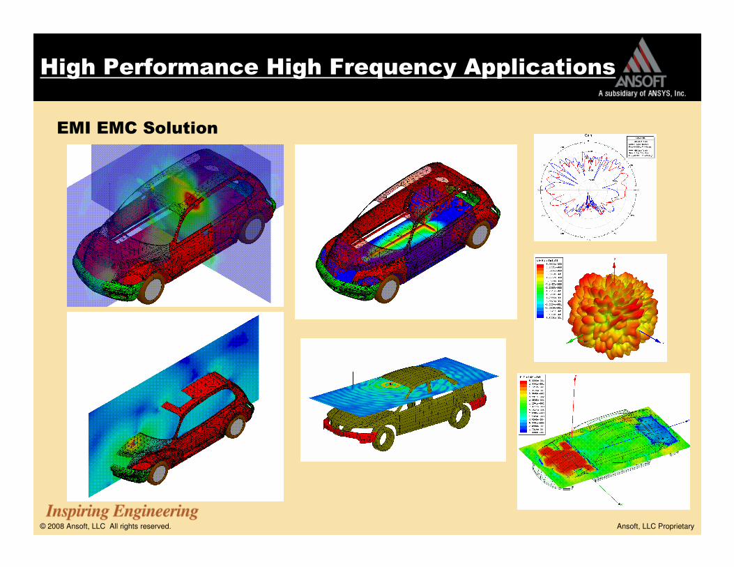
EMI EMC Solution
High Performance High Frequency Applications
© 2008 Ansoft, LLC All rights reserved. Ansoft, LLC Proprietary
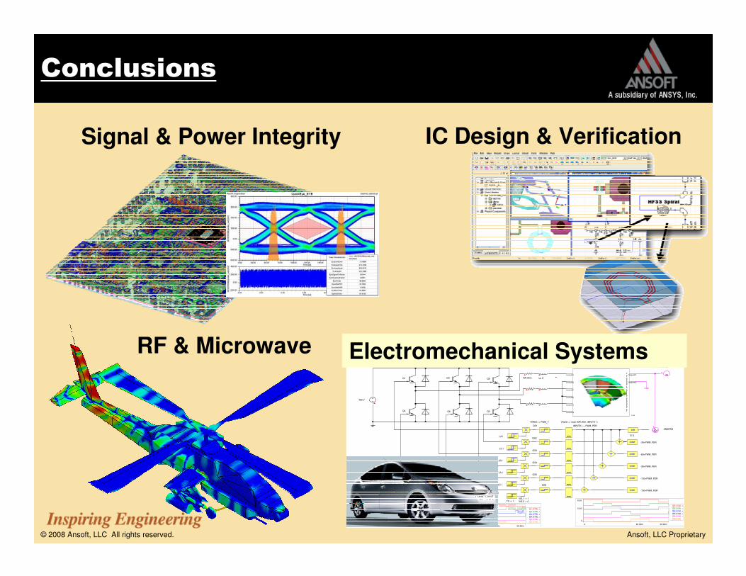
Conclusions
RF & Microwave
IC Design & VerificationSignal & Power Integrity
FEA
sourceA1
sourceA2
sourceB1
sourceB2
sourceC1
sourceC2
Magnet01
Magnet02
Name Value
FEA1.FEA_STEPS
SIMPARAM1.RunTime [s] 26.41k
SIMPARAM1.TotalIterations 34.51k
SIMPARAM1.TotalSteps 6.00k
ω+
ICA:
+
ΦGAIN
CONST
CONST
EQUBL
EQUBL
EQUBL
1500 rpm
LL:=922u
RA:=2.991
ANGRAD
57.3
-60+PWM_PER
-30+PWM_PER
QS1
QS2
QS3
VAL[0] := mod( INPUT[0] ,INPUT[1] )
PWM_T:=60
I_TARG:=9
I_HYST:=0.2
Q1
Q2
Q3 Q5
Q4 Q6
400 V
THRES := PWM_T
EQUBL
CONST
QS4
-90+PWM_PER
EQUBL
CONST
QS5
-120+PWM_PER
EQUBL
CONST
QS6
-150+PWM_PER
RA Ohm LL H
LDUM:=10m
0
8.50
5.00
0 30.00m20.00m
Q1.CTRL + 7.50
Q2.CTRL + 6.00
Q3.CTRL + 4.50
Q4.CTRL + 3.00
Q5.CTRL + 1.50
Q6.CTRL
-10.30
10.00
0
0 30.00m20.00m
LA.I [A]
LB.I [A]
LC.I [A]PWM_PER:=180
INPUT[1] := PWM_PER
INPUT := -LB.I
LC.I
-LA.I
LB.I
-LC.I
LA.I
THRES1 := I_TARG - I_HYST
THRES2 := I_TARG + I_HYSTVAL1 := 1
VAL2 := 0Y0 := 1
-14.50
7.80
0
0 30.00m20.00m
Torque Output
-30.00k
302.00k
200.00k
0 30.00m20.00m
FEA Outputs
FEA1.WIRELOSS
FEA1.CORELOSS
FEA1.IsourceA
FEA1.VsourceA
FEA1.EIsourceA
FEA1.FLUXsourceA
FEA1.IsourceB
FEA1.VsourceB
FEA1.EIsourceB
FEA1.FLUXsourceB
FEA1.IsourceC
FEA1.VsourceC
FEA1.EIsourceC
FEA1.FLUXsourceC
FEA1.PHI
FEA1.OMEGA
0
8.50
5.00
0 30.00m20.00m
QS1.VAL + 7.50
QS2.VAL + 6.00
QS3.VAL + 4.50
QS4.VAL + 3.00
QS5.VAL + 1.50
QS6.VAL
Electromechanical Systems