annual report...strategy - innovative, neutral, global -” striving to develop innovative...
TRANSCRIPT

ANNUAL REPORTFY2014
April 1, 2014 - March 31, 2015
Railway Technical Research Institute

Since the Japanese fiscal year (FY) 2014 was the final year of RTRI’s five-year master plan “RESEARCH 2010,” we have continued research activities to achieve the goals of the master plan. We have implemented 280 research projects in three key areas, that is, research and develop-ment for future railways, development of practical technologies, and basic research on railways.
As part of research and development tasks for future railways, we focused on achievements intended to improve the safety and reliability of railway systems, such as simulators for earthquake motion and earthquake damage on railways, disaster hazard mapping technologies, and derailment-resistant railway cars. In this report, we have overviewed the results of our five-year research activities on using energy more efficiently, maintaining and expanding railway net-works, revolutionizing maintenance, and building railway simulators. To develop practical technolo-gies, we developed an early earthquake warning system in which seabed seismometer data are used, Shinkansen car gear oil to improve low-temperature starting, and a tunnel micro-pressure wave reduction method. In basic research on railways, we tackled themes necessary to resolve various railway-related problems: methods to decide announcements and warning sounds in train drivers’ cabs, methods to predict inductive disturbance on telecommunication lines cover-ing the data transmission frequency bandwidth, stability evaluation methods for bedrock slopes by remote non-contact measurements, clarification of the mechanism of wear of the current collecting system materials caused by current flow, and clar-ification of the mechanism causing car vibration in tunnels. In our efforts to conduct research and development more efficiently on global issues, we
have initiated joint research with three overseas research institutes. In addition, we undertook activities related to international standards set by the International Electrotechnical Commission (IEC) and the International Organization for Standardization (ISO).
In order to respond to the demands of the railway industry and society, RTRI has newly en-acted its vision “RISING: Research Initiative and Strategy - Innovative, Neutral, Global -” striving to develop innovative technologies to enhance the railways to contribute to the creation of a happier society. Based on our vision, we have established three missions, ‘Dynamic research and development,’ ‘Neutral activities based on technological common sense,’ and ‘Activities that lead global technology.’ We have initiated more concrete projects and adopted management strategies to accomplish these missions. We also formulated RESEARCH 2020, our first master plan based on this vision, and began to implement it at the beginning of FY 2015. The master plan calls for our activities to prioritize the performance of dynamic research and development aiming for innovative research and development and the creation of top-quality research achievements that demonstrate our overall strength.
I am confident that the value of the existence of RTRI can be enhanced by earning trust through high-quality results. We will not only tackle the challenges of safety, energy, and greater speed, but also efficiently invest our limited research resources, thereby creating benefits that will rapidly and accurately meet the needs of railway companies. In order to achieve this goal, the guid-ance and advice by all the railway stakeholders are most appreciated.
1Annual Report 2014-2015
Foreword
Norimichi KUMAGAIPresident

Overview
ExecutiveVicePresidents
Board of Trustees
Auditors
Board of Directors
ExecutiveDirectors
Railway TechnologyPromotion Center
Marketing & BusinessDevelopment Division
International Division
Railway InternationalStandards Center
Accounting Division
Planning Division
PresidentChairman
Miyazaki TestCenter
Administration Division
Vehicle Structure Technology Division
Vehicle Control Technology Division
Structures Technology Division
Power Supply Technology Division
Track Technology Division
Signalling & Transport Information Technology Division
Disaster Prevention Technology Division
Materials Technology Division
Railway Dynamics Division
Environmental Engineering Division
Human Science Division
Maglev Systems Technology Division
Information Management Division
Health InsuranceSystems Center
Research & DevelopmentPromotion Division
Wind TunnelTechnical Center
Yamanashi Maglev Test Center
Compliance Division
Center for Railway Earthquake Engineering Research
Internationalaffairs
InternationalDivelopment
Organization
2 Annual Report 2014-2015
Contents2 Overview
4 Major Results of Research and Development
34 Research and Development
56 Report on Key Activities under the Previous Master Plan RESEARCH 2010

ExecutiveVicePresidents
Board of Trustees
Auditors
Board of Directors
ExecutiveDirectors
Railway TechnologyPromotion Center
Marketing & BusinessDevelopment Division
International Division
Railway InternationalStandards Center
Accounting Division
Planning Division
PresidentChairman
Miyazaki TestCenter
Administration Division
Vehicle Structure Technology Division
Vehicle Control Technology Division
Structures Technology Division
Power Supply Technology Division
Track Technology Division
Signalling & Transport Information Technology Division
Disaster Prevention Technology Division
Materials Technology Division
Railway Dynamics Division
Environmental Engineering Division
Human Science Division
Maglev Systems Technology Division
Information Management Division
Health InsuranceSystems Center
Research & DevelopmentPromotion Division
Wind TunnelTechnical Center
Yamanashi Maglev Test Center
Compliance Division
Center for Railway Earthquake Engineering Research
Internationalaffairs
InternationalDivelopment
Organization
(As of July 1, 2015)
3Annual Report 2014-2015
Railway Technical Research Institute

IMPROVEMENT OF SAFETY
1. Seismic ground motion simulator applicable to M9 earthquakes
• The simulator can estimate seismic ground motion during M9 earthquakes.• In the 2011 off the Pacific coast of Tohoku earthquake, the difference between observed and simulated
values in terms of the JMA seismic intensity scale was within ±1.• Simulated ground motion can be used for seismic retrofitting of structures to withstand the forecast
great earthquake along the Nankai Trough.
Major Results of Research and Development
The 2011 off the Pacific Coast of Tohoku Earthquake was a massive earthquake of a magnitude of 9.0 caused by a subduction area measuring 500 km long and 200 km wide. Seismic ground motion was observed across the whole of Japan, and caused liquefaction damage as far away as in the Kanto Region. In order to simulate the ground motion of the next forecast M9 earthquake, it is necessary to simulate dynamic rupture on a large fault plate and the propagation of ground motion across a vast area .
This simulator was therefore designed to represent dynamic fault rupture processes and 3-dimensional varia-tions in deep subsurface structures. Information about fault models and deep subsurface structures has already
been stored a database, allowing simulation of seismic ground motion to be conducted easily with limited input data, such as the area used for calculation and source location, etc. When the simulator was used to simulate the ground motion which occurred during the 2011 off the Pacific Coast of Tohoku Earthquake, it was able to repro-duce the long duration ground motion in the Kanto Region located far away from hypocentre, even 250 seconds after the earthquake occurred (Figure 1). As shown in Figure2, the difference between observed and simulated values in terms of the JMA seismic intensity scale was accurate to within ± 1, validating the applicability of the simulator for M9 earthquakes.
The Government Headquarters for Earthquake
fig.1 Simulated velocity value during the 2011 off Pacific coast of the Tohoku Earthquake (Long period components)
fig.2 Comparison of observed and simulated values, in terms of JMA instrumental seismic intensity, during the 2011 off Pacific coast of the Tohoku Earthquake
In fiscal 2014, we pushed ahead with 280 research and development projects and completed120 of them. Major results of the research and development are shown below.
4 Annual Report 2014-2015

IMPROVEMENT OF SAFETY 2. Seismic Hazard simulator for railways
Research Promotion has released information that there is a 60-70% probability of a great earthquake occurring along the Nankai Trough over the next 30 years. Using the
simulator, it will be possible to evaluate damage to railway structures and identify points which would be particularly vulnerable during a forecast great earthquake, in advance.
A simulator was developed to identify locations which were vulnerable to earthquakes on the railway network (Figure 1). Data regarding the fault, ground and structures were collected into a database. By using the data, the simulator constructed numerical analysis models of the fault, ground, and structure, in order to evaluate the seismic response of the ground and structures. Information about damage obtained through analysis of the data was then linked to map information, in order to allow visualization of structural damage in disaster hit areas.
The simulator selects the most appropriate analytical model depending on the type and volume of data. When detailed data is available, a three-dimensional FEM model for the area from the fault to the bedrock, a two-dimensional FEM model for the surface subsoil and a three-dimensional skeletal frame model for the structure are used. This method provides a seismic response analysis of an ac-curacy which satisfies design calculation requirements.
Accuracy of the method was also tested by compar-ing estimations with data from the 1995 South Hyogo Earthquake, and evaluating the seismic response and damage to structures over a 13 km stretch where dam-age was particularly severe (Figure 2 (a)). The structures examined were 69 viaducts. Seismic intensity evaluated using the simulator gave estimations accurate to within a margin of ± 0.5 with measured data (figure 2 (b)).
Accuracy of structural damage evaluation, in terms of identifying those structures which require restoration, produced results with an error margin of approximately 12% (still within safety side assessment) (Figure 2 (c)).
These results indicate that the method is precise enough to detect vulnerable spots on the railway network.
With the prospect of the forecast large-scale earth-quake directly beneath Tokyo, and a Nankai – Tonankai Earthquake, it is important to be able to plan seismic reinforcement work, and construct recovery scenarios. This simulator should serve as a supporting tool in this regard.
• A simulator was designed to identify locations on the railway network vulnerable to earthquakes • Comparison of simulated results with actual damage confirmed the accuracy of damage evaluation
using this simulator.• The simulator can be used to determine locations requiring preventive reinforcement work and forecast
restoration work scenarios.
Fig.2 Example of accuracy verification
Fig.1 Seismic Hazard simulator for railways
5Annual Report 2014-2015
Railway Technical Research Institute

3. Early warning system employing ocean bottom seismometer data
Japan is currently expanding its ocean bottom seismom-eter OBS) network (Figure 1). Data about earthquakes occurred beneath the sea collected through this network is used for issuing early earthquake warnings, which can be useful for railway earthquake disaster prevention. As such a method was designed to employ OBS data in early warnings, while telecommunication specifications and quality management technology were developed to maintain early warning reliability.
In the proposed method the OBS data sent to land observation stations through undersea cables is used to calculate the indicators which will determine whether a warning should be issued or not. The data is sent via telecommunication networks to the railway operators to-gether with other information which indicates the quality of the data. While taking into account data quality, railway operators then issue a warning if the indicators exceed the regulatory threshold value (Figure 2).
Technology was then developed which immediately calculates data quality information based on waveform observation which indicates missing data, noise, etc. to ensure warning reliability, and which railway operators can refer to when deciding whether to issue a warning or not (Table 1).
To enable multiple railway operators to share the subma-rine seismographic data telecommunication specifications were subsequently defined to enable transmission of data through a limited frequency band telecommunications line.
It is expected that using OBS data should increase the spare warning time for earthquakes by approximately 20 seconds at most.
• This method proposes to employ ocean bottom seismometer data collected by public institutions for an early warning system.
• Telecommunication specifications and quality management technology are also proposed, in order to guarantee the reliability of the warnings.
• The proposed method should increase the spare warning time for marine earthquakes occurring ear submarine observation points.
Fig.1 Position of measurement points forming part of the ocean bottom seismometer network operated by public institutions
Fig.2 Process flow chart for the early warning system using ocean bottom seismometer data
Table.1 Quality Management Information for Data
Major Results of Research and Development
6 Annual Report 2014-2015

4.Development of Railway Embankment Structures Resistant to severe Earthquakes and Prolonged Overflows caused by Tsunamis
Railway embankments sustained extensive damage from the tsunami triggered by the 2011 off the Pacific coast of Tohoku Earthquake and the operations of railway lines were suspended for an extended period of time. A new reinforced embankment design was therefore developed to resist seismic motion and prolonged overflows caused by Tsunamis.
Tests on a model embankment were first carried out in order to gain insight into the causes of tsunami damage. Results showed that seismic motion weakens the levee part and slope protection of the embankment. Subsequent tsunami overflow then erodes the embankment levee and the supporting ground around the toe of the slope, leading to overall instability, and eventually to collapse.
Therefore, by arranging geosynthetics reinforcement materials inside the embankment and the protective slope, resistance to seismic motion and prolonged overflows can
be improved. In addition, cement-treated gravelly-soil slabs were added to the bottom of the embankment levee using both cement-treated well-graded gravel and geosynthet-ics. The combined use of these reinforcement measures comprises the new method designed to prevent erosion of the supporting ground due to scouring and subsequent instability of the embankment (Figure 1).
Tests on model embankments showed that the conventional type embankment resisted well to a large scale earthquake (L2 seismic motion), however half of the embankment was eroded within 6 minutes of tsunami overflow. On the other hand, the newly developed embank-ment was hardly affected by erosion at all (Figure 2).
Preparation of a technical manual indicating practical design and construction methods for the proposed struc-ture is planned for the future.
• A new design method and embankment structure have been developed to reduce earthquake damage and increase resistance to prolonged overflows caused by tsunamis, by combining geosynthetics reinforced soil methods and cemented gravelly-soil slabs.
Railway Technical Research Institute
Fig.1 newly developed embankment structure
Fig.2 comparison of conventional
7Annual Report 2014-2015

5. Measures against buckling of ballasted track during earthquakes
As seismic motion is acting on ballasted track, lateral ballast resistance force falls, causing track panels to buckle easily. During hot periods over the summer, rail temperature (axial force) rises increasing the lateral force which can lead to track buckling, and consequently further reducing track buckling stability during seismic activity. At the same time, no method has yet been established to assess the track buckling stability during earthquakes, making it difficult to evaluate the effectiveness of measures taken.
A test method was developed using special springs with small tensile load variation whereby the lateral load on the sleeper can be maintained even during shaking. Tests on a large scale shaking rig demonstrated that it was possible to
quantitatively evaluate the track buckling stability of various anti-buckling measures, through indices based on lateral sleeper displacement (Figure 1).
Indoor tests at RTRI showed that lateral ballast resis-tance force greatly decreased during shaking, and when axial forces of rails (lateral direction loads) were high, lateral sleeper displacement was also significant (Figure 2). It was then possible to confirm that anti-buckling measures did indeed reduce lateral sleeper displacement significantly. It was found in tests that the sleeper anchor was the most effective of all the tested measures, reducing lateral sleeper displacement by a tenth under this test conditions (Figure 3).
Fig.1 Large-scale shaking table test for ballasted track
• A test method was developed to quantitatively evaluate the stability of buckling on ballasted track during earthquakes.
• Based on results of this evaluation method, it was found that employing sleeper anchors could reduce lateral sleeper displacement during earthquakes by up to a tenth, thereby confirming improved track buckling stability.
Fig.2 Lateral ballast resistance force during, before and after shaking
Fig.3 Effectiveness of anti-buckling measures against earthquakes
Major Results of Research and Development
8 Annual Report 2014-2015

6. Disaster Hazard Mapping Technology
Hazard mapping for natural disasters is useful for railway maintenance and disaster prevention planning. Having a system which could show various natural disaster factors in an integrated display would facilitate evaluation of many different types of disaster scenarios for disaster prevention planning, and make it easier to identify the sources and external forces involved. Such a system would also facilitate the design of effective countermeasures.
To this end, hazard mapping technology was developed to visualize the evaluated probability of disaster occur-rences frequently occurring along railway lines, such as landslides, strong winds, avalanches, rockfalls etc., and the safety factor of slopes adjacent to railway lines, in map form using GIS (Geographic Information System).
The probability of disasters and safety factors are evalu-ated from extracted hazard factors, such as slope angles and distribution of exposed rock, and estimated external
forces such as amount of precipitation, wind speed and direction (Figure 1).
A combination of methods already developed by RTRI and a new technique for extracting data about ground surface changes using airborne LiDAR (Light Detection and Ranging) and large area stability analyses of slopes during rain, was used to extract disaster factors, estimate external forces and evaluate the probability of disaster occurrences.
Using the newly developed hazard mapping technology, it will be possible to visualize spots vulnerable to natural disasters. This new system will be a useful tool for disaster prevention planning, since it will be possible to visualize on one single display not only the probability of occurrences of different types of natural disasters, but also their disaster factors and the magnitude of external forces.
• New technology has been developed to permit the display of natural hazards related to rain, wind, snow and rockfalls, in map form.
• The integrated display can show disaster factors, the magnitude of external forces and probability of occurrence together, thus assisting the preparation of disaster prevention plans.
Railway Technical Research Institute
Fig.1 Disaster hazard mapping technology
9Annual Report 2014-2015

7. Method for diagnosing condition of concrete roadbed in tunnels
Repeated loading from passing trains on slab track in tunnels with no invert can cause subsidence of the track bed leading to concrete track bed deformation and track irregularity (Figure 1). These problems can be detected through abnormal track geometry readings, however, up until now it has been very difficult to determine whether these problems arise because of the track bed or the track itself.
A method was therefore developed to diagnose the primary cause of track bed subsidence, by obtaining the transfer function (the ratios of the concrete track bed re-sponse frequency amplitudes obtained for each vibration frequency input to the vibrator) surface areas (in terms of ease of oscillation) obtained from excitation tests on a concrete track bed, which were used as indices, where larger values indicate the primary cause is located on the
track bed side, while smaller values show that it is on the track side (Figure 2).
Application of the method to an actual tunnel, and vibration test results from before and after injection of the material were applied to cavities under the track bed concrete confirming the effectiveness of the proposed system (Figure 3).
A numerical analysis model was built to reproduce these phenomena. It was found that there was a good correlation between the transfer function surface area of the concrete obtained during excitation tests and the rate of cavity occurrence directly beneath the concrete track bed. This leads to the conclusion that it is possible to detect cavities directly beneath the concrete track bed from on-site measured results (Figure 4).
Fig.1 Existence of cavities under the slab track surface
• A vibrating device was designed to facilitate the diagnosis of the state of health of concrete railway roadbeds in tunnels.
• Based on the concrete roadbed’s ease of movement, it is possible to determine whether or not it has developed cavities.
Fig.3 Vibration device test results before and after injecting grout mixture
Fig.4 Estimation of porosity using surface area of transfer function
Fig.2 Diagnosis method to determine condition of concrete road bed in tunnels
Major Results of Research and Development
10 Annual Report 2014-2015

8. Analytical method for evaluating carbody safety aimed at reducing passenger injury in case of level crossing collisions
Reducing passenger injury in case of a level crossing collision is a major issue. It is possible to calculate the carbody impact acceleration from analyses of train col-lisions with obstacles, however, it is difficult to evaluate injury to passengers. Therefore, in order to probe carbody impact acceleration inside a train in level crossing collision, impact analyses were conducted of a train colliding with a dump truck full of sand (overall weight 22 tonnes), using train speed as a parameter (30-130 km/h) (Figure 1).
The longitudinal carbody impact acceleration pulses obtained through these analyses were used as input for analysis of passenger behavior seated either on long seats or cross seats, which in turn were used to calculate an injury index (Figure 2). When the passenger injury index
neared the limit level, the carbody impact accelerations were integrated as shown in Figure 3. This figure shows that there is a clear threshold which determines whether or not the injury index exceeds the limit level. The integrated acceleration value at the moment a passenger either col-lided with a partition wall or with the seat in front shows a close proportional relationship with the passenger injury index value (Figure 4).
The results of these investigations demonstrated that the integrated value of carbody impact acceleration was an effective index which could be used to reduce passenger injury. These results can also be used to establish carbody design guidelines to improve safety against collisions.
Fig.1 Example of train collision analysis(collision speed 54km/h)
• A relationship was identified between passenger injuries in level crossing collisions and the integrated value of carbody impact acceleration.
• It is possible to reduce passenger injuries in level crossing collisions by designing the carbody structure to lower the integrated value of the carbody impact acceleration.
Fig.3 Example of relationship between waveform of integrated value of carbody impact acceleration and injury of passengers sitting on long seats
Fig.4 Example of relationship between integrated value of carbody impact acceleration and head injury criterion
Fig.2 Evaluation of seated passenger injury
Railway Technical Research Institute
11Annual Report 2014-2015

9. Bogie to control decrement in wheel load
When rail vehicles run through curves with largely twisted tracks , such as transition curves emerging from a main curve, it is possible that the torsion between the vehicle bogie and the rail surface will cause a decrease in wheel load on the outside wheel of the front axle (in relation to the driving direction). When large lateral forces are associated to this, flange climb occurs causing a risk of derailment. Decrease of wheel load or lateral force suppression control is an effective means to prevent flange-climb derailment.
In order to suppress decrease in wheel load, a bogie was developed which is able to control decrements in wheel load (Figure 1) for use on conventional trailer vehicles, in the form of a rotating mechanism installed between the side beams and cross beam of the bogie frame. The right and left side beams of the bogie can rotate freely in the pitching direction through the rotating mechanism.
Consequently, the device offsets the torsion generated when the vehicle moves through large horizontal plane variations on the track, controlling decreases in wheel load and thereby improving safety against flange climb derailment.
In order to verify the basic functions of the new device, running tests on a transition curve after a main curve on the RTRI test line were conducted. Results showed that compared to normal bogies where the side beam and cross beam are welded together, the new frame controlled and managed to reduce decrease in wheel load by a maximum of about 40% (Figure 2).
Further running tests on the rolling stock test bench showed that running safety was not impaired even at a speed of over 300km/h confirming that the new device does not have a negative impact on running stability.
• With a view to increasing protection against flange climb derailment, a bogie was developed which suppresses decreases in wheel load with a rotating mechanism installed between the side beams and cross beam on a bogie frame
• Confirmation was obtained that this new system suppresses decreases in wheel load by approximately 40% compared to normal bogies.
Fig.1 Bogie control of decrements in wheel load
Fig.2 Effectiveness of wheel load-decreasing suppression (on exit of transition curve, in bend with radius of 160m)
Major Results of Research and Development
12 Annual Report 2014-2015

10. Mechanical pneumatic steering system with failsafe function
Proposals have been made for steering systems which improve driving performance through curves by extending the wheel base on the outer rail, however, given the risk of reverse steering due to an operational malfunction in an electrically powered steering system, the proposal was not adopted for practical development. Following this, a safer steering system was developed which performs mechani-cal steering control based on the angle between the vehicle and the bogie when driving through a curve (Figure 1).
The proposed system does not require electrically pow-ered control for steering due to the new link mechanism which connects the device which detects the bogie angle based on interaction between the vehicle and the bogie while running, with the compressed air control valve for supplying compressed air to the steering actuator.
The steering actuator also has a built-in anti-reverse steering valve, creating a mechanism where active steering with compressed air is only possible in the direction of the self-steering force of the wheel. At the same time, if a malfunction arose with the air distribution system, the
normal longitudinal stiffness of the primary suspension acts as a fail-safe mechanism.
Tests on a vehicle equipped with the proposed system showed that the new steering device reduced lateral forces by 80% compared to no steering control (Figure 2). Furthermore, in the case of a hypothetical malfunction causing reverse steering, confirmation was obtained that the anti-reverse steering valve prevented an increase in lateral force.
As the present system was built for a bolsterless bogie, it can be made light and compact with the same level of performance for heavier, more complex, bolstered bogie-angle linked steering trucks.
Future tasks for the development of this device include high-speed performance tests which could not be con-ducted on the running test track at RTRI, and durability tests on the bogie angle detection device, which are required before placing the system into service.
• A mechanical pneumatic steering system has been developed, which is light weight, compact and does not reverse steer
• Running tests at RTRI confirmed that the new system reduces lateral forces by 80% in curves.
Fig.1 Structural components of the mechanical pneumatic steering system
Fig.2 Results of running tests at RTRI
Railway Technical Research Institute
13Annual Report 2014-2015

11. Gear oil for Shinkansen trains with improved startability in low temperature conditions
The Shinkansen network is being extended to regions which are exposed to cold weather. Gear oil for Shinkansen trains therefore needs enough fluidity to start gear units at low temperatures of around -30°C, while having sufficient viscosity to allow oil film formation at high temperatures.
The increase in viscosity at low temperatures of current gear oil however means that resulting fluidity at -30°C is insufficient. However, gear oil which uses synthetic base oil is more expensive than the gear oil used at present. Therefore, a new gear oil was developed which not only has sufficient fluidity at these low temperatures but also keeps extra cost to a minimum and ensures gear units are able to start at low temperatures of around -30°C (Figure 1). The developed gear oil uses a highly purified mineral
oil as the main base oil, which is purer than the one used in current gear oil, and contains different additives.
Tests on the state of the gear oil at low temperatures demonstrate a lower viscosity at temperatures of -20°C, and a depression in the pour point, confirming better fluidity at low temperatures (Table 1).
Starting tests on a gear unit in a cold environment showed that even when the oil level has fallen to the minimum limit, the gear unit was able to start stably at a temperature of -30°C (Table 2).
Tests confirmed that oxidation stability, resistance to loads and anti-wear performance of the new gear oil, were comparatively the same or better than in the current oil.
• An improved gear oil has been developed to permit safe starting of gear units at temperatures as low as -30°C
• This highly purified mineral base oil offers better low temperature fluidity, with reducing cost increase.
Fig.1 Change in kinematic viscosity according to tempera-ture of current and developed oil
Table.1 Properties relating to low-temperature fluidity
Table.2 Results of low temperature starting performance tests (-30°C )
Major Results of Research and Development
14 Annual Report 2014-2015

12. Process to select appropriate sounds to convey in-cab driver alerts
A rise in recent years in the type and variety of driving assistance and safe-guard technologies, a growing number of sounds emitted inside driving cabs, and an increasing variety of tones used for warning devices has raised the concern that this may distract or affect the concentration of drivers, and therefore work has begun on developing a design guideline to unify sound alerts.
A chart has been proposed for designers to help choose sounds when adding any new sound alerts.
The importance of the information to be conveyed was split into four categories (hazard level) according to likeli-hood of an accident, and selection criteria were devised for each category (Table 1 ).
The chart contains example sounds and voice mes-sages for each hazard level based on the degree of urgency they made drivers perceive.
A checklist is proposed to guide the selection between sound and voice, based mainly on frequency of use,
characteristics of the sound which could be confused with existing alerts, and to limit number of the sounds to an acceptable level, etc .
Methods for determining sounds according to urgency of the warning already exist in the automobile and aviation sector. However, the railway environment is very different, given the type of information, the complexity of required responses, the supposed sound environment and the existing visual and audio information burden.
Consequently, based on interviews with those responsi-ble for system design, and tests and surveys with on-board staff, a classification and voice-notification method suited to railways has been proposed.
By adopting a uniform approach to in-cab information drivers will be able to instinctively perceive hazard levels, while it would also reduce the possibility of selecting easily confused sounds and allow clear delivery of the intended message to drivers.
Table.1 Process and decision-making factors for selecting sounds (extract)
• A process has been developed to select what kind of sound signals should be used for in-cab alarms or alerts.
• This process facilitates the selection of sounds or voice messages to match the level of urgency.
Railway Technical Research Institute
15Annual Report 2014-2015

HARMONY WITH THE ENVIRONMENT13. Training in communication techniques for train dispatchers in disrupted situations
In traffic control, it is important to share information accurately and smoothly between key employees, such as between traffic controllers managing traffic, crews and train vehicles.
To address this challenge, a training method in com-munication techniques was developed which is easy to implement in the workplace (Figure 1).
Participants to the training were divided into groups according to roles, and then exposed to a simulated dis-rupted situation where they were required to communicate with each other. Their behavior and conversations were videoed during the training, and they viewed these record-ings together after the drill. One to two months after the training, checks were made to see if the program helped participants to communicate better in the course of their ordinary work, which was followed by a final round of feedback on the training.
A list was drawn up of 45 points to remember in terms of communication skills, such as “when there is danger, your voice should be more assertive”, etc. Two types of questionnaire were compiled for each of the 45 points. The first asked “how important do you think these techniques are?” and the other asked “to what extent do you apply these techniques at work?” These questionnaires proved to be an effective way to measure how the acquired skills had been adopted and applied, even some time after the training, and helped to accelerate the acquisition of com-munication techniques.
Confirmation was obtained that this training increased awareness of the importance of communication techniques while it also increased actual application of these skills in the workplace (Figure 2).
The present method can therefore help to reinforce cooperative behavior and smooth sharing of accurate information between relevant employees in disrupted situations.
Fig.1 Outline of training method
• A training method was developed in order to give train dispatchers the necessary communication skills for giving instructions or orders in disrupted situations
• This method was shown to improve the accuracy and smoothness of communication in disrupted situations, and cooperative behavior.
Fig.2 Comparing before and after training in communication techniques
Major Results of Research and Development
16 Annual Report 2014-2015

HARMONY WITH THE ENVIRONMENT
14. Hood with inside partition to reduce micro-pressure waves
Tunnel entrance hoods, which are installed at tunnel entrance portals (where trains enter the tunnel), are a common infrastructure-side measure used today to re-duce micro-pressure waves emitted from tunnel portals. Tunnel entrance hoods have to be extended in line with train speed, however, beyond a certain length the hood is no longer effective, which is a problem.
Therefore, in order to meet new demands associated with increasing train speeds, a proposal has been made for a new infrastructure-side measure, i.e. to install a hood with an inside partition at the tunnel exit portal (the train exit side). Like existing tunnel entrance hoods, the new hood has a larger cross-sectional area than that of the main tunnel. It has a partition which divides the inside of the hood into two parts in the vicinity of its mouth, and one end of the partition is closed (Figure 1).
The partition splits the compression wave inside the tunnel, which is the source of micro-pressure waves, and although the micro-pressure waves are still emitted several times, the system reduces its peak value (Figure 1).
According to acoustic theory, the effectiveness of this hood with an inside partition on reducing micro-pressure waves should be approximately proportionate to the opening ratio (Opening cross-sectional area / hood cross-sectional area), (provided 0.5< opening ratio<1). Model tests validated the acoustic theory conclusion confirming the effectiveness of the hood (Figure 2).
In the case of suppressing micro-pressure waves gener-ated by oncoming trains entering the tunnel at an end equipped with one of the new hoods, if the cross-sectional area of these new hoods and open windows distributed along its length are suitably adjusted, the new hoods will maintain the same functional performance as existing hoods of the same length.
• As a measure to reduce micro-pressure waves as Shinkansen train speeds increase, a hood with an inside partition has been developed. The micro-pressure wave mitigating properties of these hoods were verified using theoretical analysis and model experiments.
Railway Technical Research Institute
17Annual Report 2014-2015
Fig.1 Micro-pressure wave emission from the hood with inside partition
Fig.2 The reduction ratio of the micro-pressure wave by hood with inside partition

15. Improved accuracy train energy consumption simulator
In order to reduce energy consumption in the railways , various kinds of both fixed installations and rolling stock side solutions are being investigated, and more accurate energy simulators are required to estimate the efficiency of each of these measures.
To this end, a traction power supply simulator was developed. Detailed calculations were made of the in-teraction between current and voltage between several trains and several traction substations, with precise speed profiles reflected by changes in acceleration due to voltage changes . In order to verify the fidelity of the simulator, comparisons were made between calculated and mea-sured values obtained from tests using two trains running through a feeding section with two temporarily isolated substations. The results showed the correlation between the feeder current and the train speed was almost identical (Figure 1). It was confirmed that data about the trains’ energy consumption could be calculated to within 5%, and power for the substation to within 8 %.
It is well known that energy consumption varies greatly in accordance with driving patterns, and therefore simula-tions need to be made by generating speed profiles which are as close as possible to reality. Two algorithms for gen-erating speed profiles were developed: one for generating a speed profile for energy estimation, utilized to calculate average energy consumption of train operations, and one for generating an energy-saving speed profile which can be an example of train operations to reduce energy consumption. Verifications were made to ensure that the speed profile for energy estimation was indeed a realistic representation of actual driving, and its energy consump-tion was also close to the averages found in commercial train operations (Figure 2). Another result confirms that the low energy speed profile will enable energy-saving operations to be made.
• A traction power supply simulator has been developed with coupled analysis between fixed installations, rolling stock and driving pattern.
• An algorithm for generating speed profiles was developed to generate average energy consumption speed profiles during commercial service, and energy-saving speed profiles.
Major Results of Research and Development
18 Annual Report 2014-2015
fig.2 Verification of algorithm for generating speed profiles
fig.1 Verification of traction power supply simulator

16. Induction predicting simulator applicable to data transmission frequency bands
Induction voltage and current in trackside telecommu-nication lines are caused by feeder voltage and ground return current (Figure 1). As a means to prevent problems such as electrocution and interference with telecommu-nication lines, countermeasures of equipment based on results of prediction calculations have been implemented.
However, existing methods for calculating induction predictions could only be used in audio frequency bands. Also these methods modified calculated values by con-sidering influence from cable structures and iron rebars in civil structures, which means that the calculated values were generous approximations of induction occurrence.
Therefore, a new induction predicting simulator was developed, which is applicable to high frequency band above the audio frequency and capable of considering multiple conductors in structures.
The simulator uses a new method where parameters are calculated by suitable approximation equations which take into account the ground effect and the skin effect of conductors, while the model is split into smaller sections as the frequency range increases, extending the frequency range from the audio frequency band of 4 kHz up to the data transmission band of 1 MHz (Figure 2).
While the new simulator removes the limit on the num-ber of longitudinal conductors which was several dozen in old simulators, its calculation speed is also faster by using
parallel processing which is used for models with very large calculation loads. Therefore, installation conditions can be considered in great detail, and the prediction accuracy was increased by about 10% (Figure3).
The simulator will make it possible to quantitatively evaluate the effectiveness of anti-induction countermea-sures to reduce induced voltage and induced current on telecommunications lines, when upgrading or installing new power, or wire-based telecommunications equipment. The simulator can also be used for predicting voltage and current induction in rails.
fig.2 An example of prediction results in the data transmis-sion frequency band
fig.3 Overview of calculation models of viaduct and result of validation of the models
• A simulator was developed for quantitatively predicting inducted voltage and current up to data transmission frequency bands of 1MHz and above.
• The extended ability to consider more conditions relating to fixed installations has led to an improvement of 10% in accuracy of prediction.
Railway Technical Research Institute
fig.1 Electromagnetic induction and Electrostatic induction occurring
19Annual Report 2014-2015

17. Production of a 300m class superconducting feeder cable
Before placing superconducting feeder cables into ser-vice on railways, several issues have to be resolved and methods found for, among others, laying the cable along the line, mitigating thermal stress which occurs in the cable during cooling, cooling technique to ensure superconduct-ing properties are preserved over a long distance, etc.
A prototype superconducting feeder cable system was laid along the test track at RTRI (Figure 1), and running tests were performed. The system was sized according to the length of a typical feeder section i.e. 310 m, with a rated current of 1000A. In order to reproduce conditions as close to reality as possible, the test line was constructed with a track cross over, a level crossing section and a thermal stress mitigation structure in the cable during cooling.
T h e r u n n i n g t e s t s w e r e p e r -
formed after verifying the electrical properties, such as withstanding voltage, of the superconducting feeder cable, and those of the cooling system (Figure 2), which confirmed the conductive properties of the system during operation.
Given the superconducting feeder cable’s capacity to supply electricity with zero electrical resistance, it can be used as a measure to prevent voltage drops and reduce loads on traction substation, etc. Future work is on con-ducting field tests with the new system, and designing a technical architecture to place the system into active service.
• A 310 m superconducting feeder cable was built along with a cooling system. Its functions were then verified with running tests.
fig.2 Cooling system
fig.1 310 m superconducting feeder cable
Major Results of Research and Development
20 Annual Report 2014-2015

COST REDUCTION
18. Renovation technology for large scale station widening work
Facing the growing need in large city undergrounds to reduce congestion and improve functionality there is increasing recourse to station extension work where part of an existing underground tunnel is opened and connected to a new tunnel to widen the area. However, large scale extension work involves significant reinforcement of the existing tunnel.
A new working method was therefore developed, which combines vertical and horizontal anchors crossing over, overlapping onto the existing tunnel (on the ground side) with a projected reinforced beam (Figure 1).
The reinforcement beam supporting the structure in the track direction serves to consolidate the existing and new
tunnels into a monolithic structure ensuring transverse resistance, and which prevents any increase in sectional force in the existing tunnel. Full scale loading tests showed that the connecting section did not break, and the new and existing structure behaved as a monolithic block validating the fact that this construction method possesses the de-sired flexural capacity required for applying the proposed design method into practice (figure 2).
Trial calculations for a standard two tier, double span tunnel showed that compared to the existing method, less reinforcement work is required on the existing tunnel to carry out the extension work, which should enable a cost reduction of approximately 10%.
fig.1 Outline of connection method used in large scale extension work
fig.2 Loading testing on full scale replica
• A new design method was developed for large scale underground station extension work and building connections between old and new tunnels.
• The tunnel connecting work method can offer cost savings of approximately 10% compared with existing techniques.
Railway Technical Research Institute
21Annual Report 2014-2015

19. System for monitoring soundness of railway bridges
As railway bridges age, there is a growing demand for low-cost maintenance procedures.
Until recently, the soundness of bridges was diagnosed using field measurements, impact vibration tests etc. Now, however they can be diagnosed effectively using monitoring methods that track their soundness. As such a monitoring system was developed comprising an accel-eration sensor for measuring pier vibrations, and sensors to detect bearing point displacement between the piers and girders, powered by batteries charged using power
generated from steel girder vibrations. In addition, a wire-less transmission device was developed to add to this monitoring system to allow data to be collected remotely, without going on site (Figure 1).
It was deemed that for bridge piers, a monitoring system based on the structure’s natural frequency would be par-ticularly efficient. Therefore, a new soundness diagnosis index for bridge piers was devised, drawn from sources closely correlated to the natural frequency of bridge piers, such as the power spectral area ratio of micro-tremors
(ratio of total area to low frequency area) (Figure 2).
Confirmation was obtained that this index can be used for diagnosing the soundness of actual bridge piers over the long term (Figure 3).
fig.2 Soundness diagnosis index correlated with natural frequency
fig.1 Outline of railway bridge monitoring system
• Using wireless technology, an inspection method was developed to monitor the state of railway bridges.• A method was proposed to diagnose the soundness of railway bridge piers using indices correlated
highly with the natural frequencies of bridge piers.
fig.3 Monitoring method for the soundness of bridge piers based on proposed index
Major Results of Research and Development
22 Annual Report 2014-2015

20. System for evaluating the stability of rock slopes using remote-contactless measurements
• A remote contactless measuring system was developed to observe oscillations and the shape of rock blocks on rock slopes. A tool to evaluate the stability of these boulders by performing FEM analyses on the collected data was then developed.
• The present system allows detailed numerical analysis evaluation and simple nomogram based evaluation.
In order to prevent rockfalls from rock slopes adjacent to railway lines, it is necessary to identify unstable rock blocks and take preventive action. A method was therefore developed to enable the safe and efficient assessment of the stability slopes in hard-to-access, isolated or high-up locations (Figure 1).
The contactless vibration measuring system (Figure 1-a) can detect micro-tremors on a rock face using red or infrared laser beams at distances of ten to several hundred meters. Where possible, unstable rock block vibration characteristics are evaluated on the basis of ordinary micro-tremor data, while stable rock blocks with vibration characteristics which do not appear clearly from ordinary micro-tremor data are examined using acoustic vibration etc.
The aerial survey system (Figure 1 –b) comprises a camera-mounted radio controlled helicopter, which flies around the target rock block collecting data about its shape from aerial photographs. This data is used to semi-automatically create a FEM analysis model of the rock block (Figure 1-c).
This research offers two safety evaluation methods, one through numerical analysis, based on the dominant frequency of the boulder obtained from vibration measure-ments and on an FEM analysis model, which offers detailed stability assessment under normal conditions and in case of an earthquake (Figure 1-d); the other simpler evaluation method uses the dominant frequency to determine a falling safety factor in relation to the rock block’s boulder’s stability against collapse in nomogram form (Figure 1-e).
Railway Technical Research Institute
fig.1 Remote contactless measurement system to evaluate the stability of rock slopes
23Annual Report 2014-2015

21. Track maintenance planning systems applying very frequently measured track irregularity data
Track measuring equipment to obtain track irregularity data on a very frequent basis was introduced on Kyushu Shinkansen trains in 2009. Since then, similar measure-ment equipment has been introduced on commercial trains, including conventional trains. Given the volume of data which can be measured in this manner, there is a need for efficient data processing to use this data in high-precision prediction and track condition diagnosis methods. Based on suitable data processing and use, this high frequency data has been employed to develop a track maintenance planning system.
A model for calculating track irregularity deterioration suitable for very frequently measured data was developed. Application of this model to a section of track demonstrated that the 12-month predictions obtained using this model were high accurate to within +/- 0.16 mm (97% accuracy) (Figure 1). Then, by using historical data covering 6-month or longer periods from the previous year, it would be possible to obtain sufficiently accurate predictions with measurements taken only every half month.
A model for predicting seasonal changes in track ir-regularity was also developed, which produced equally accurate half-yearly predictions. Additional models were developed to evaluate ballast deterioration, which focuses on the durability of track maintenance work, and diagnosis of rapid deterioration of track irregularity by comparing long-term trends with latest trends in each location. These new models mean that it is now easier to use very frequently measured data to locate rapid deterioration of track irregularity and detect sections with defective ballast.
Using the above results, a frequent-measurement based track-maintenance planning system was developed (Figure 2). The locations identified as requiring track irregularity maintenance in the plan obtained by the system, were 10% closer to the actual sites needing maintenance compared with the conventional approach, indicating that this model offers plans which are a closer reflection of reality. The system can also be used for diagnosing rapid deterioration of track irregularity and ballast condition diagnosis.
fig.1 Accuracy of new prediction model
fig.2 Track maintenance planning system suite for used with frequently measured track irregularity data
• A method for predicting rapidly degrading track irregularity and diagnosis model were developed for use with very frequently measured track irregularity data, which were then used to develop a track maintenance planning system.
• In addition to track maintenance planning, the system can be used for diagnosing rapidly deteriorating track irregularity, and diagnosing track condition .
Major Results of Research and Development
24 Annual Report 2014-2015

Railway Technical Research Institute
25Annual Report 2014-2015
22. Rail gas pressure welding process applicable without specialist welding skills
• Following the development of a simplified rail end surface grinding process and automatic burner oscillator, a new gas pressure welding process for rails has been proposed, which does not require specialist knowledge or skills for operation.
• Verifications confirmed that the new process offers the same performance as the previous method.
A common rail welding method used in Japan is gas pressure welding. This technique however requires spe-cialist skills for the rail end surface grinding process and rail heating stage using a burner. A new simplified and standardized gas welding method has therefore been discussed and developed with minimal requirement of specialist skills.
Examination of the rail-end surfaces on newly manufac-tured rails revealed that the contact surface required for gas pressure welding sufficiently flat, confirming that gas pressure welding can be performed after simply removing any rust with a small-scale grinder. An oscillating pattern for the burner was proposed, which offered sufficient bonding strength, and avoided excessive melting of the rail surface during the heating process. Based on this, a standard swinging operation was set, and an automatic burner swinging device was developed, capable of reproducing the proposed swing pattern (Figure 1).
Tests were performed on the gas pressure welds on a JIS60kg standard carbon rail manufactured according to the newly developed gas pressure welding process (Table 1) to evaluate its performance. Results showed that the performance of the new welding process was equal to that of existing methods.
fig.1 Pressure welding with automatic burner oscillator
Table.1 Proposed rail gas pressure welding process (rail used in this example: JIS60kg standard carbon rail)

Major Results of Research and Development
26 Annual Report 2014-2015
23. Updating of on-board train safety database using wireless technology
• A new method has been developed using wireless technology to update the on-board safety databases on trains
• While checking data validity, this system allows efficient simultaneous updating of multiple databases.
Over recent years, the development and introduction into service, of train protection systems using on-board databases (DB) has increased. On-board databases contain safety critical data such as track data and vehicle performance data. However, upgrading these systems is very labor intensive and time consuming, since the compact flash cards used for data storage have to be changed one by one in each system.
In an attempt to improve the efficiency of the DB up-grading process, a system was developed using wireless technology, and a prototype model was built for use with the ATS-Dx train protection system (Figure 1).
The prototype was built to be able to use the license-free general purpose 5.6 GHz frequency band wireless
devices for safety data transmission, and the data valid-ity checking method was designed to guarantee safety, taking into consideration the need to cut the volume of data being transmitted (Figure 2), while a special data transmission format was devised to protect data security during transmission.
Results from tests using the prototype show that it was possible to maintain the same level of data validity as previously, and that it was possible to conduct multiple unit upgrades simultaneously.
This method will contribute to the increase in database updating efficiency when trains are brought into a depot for service.
Fig.2 Outline of method for verifying transmitted data validity
Fig.1 Outline of prototype system

Railway Technical Research Institute
27Annual Report 2014-2015
24. Device for determining AC feeder lightening arrester damage
• A device has been developed to determine whether arresters with zinc oxide (ZnO) elements have been damaged.
• Given that deterioration can be determined using this method by measuring current leakage from ground wires, power cutting is no longer required.
Lightning arresters in AC feeding circuits protect electri-cal equipment from lightning or switching surges. They usually contain zinc-oxide elements inside a porcelain bushing (Figure 1). Given that deterioration of lightning arresters exposes electrical equipment to damage, it is necessary to grasp the state of these arresters on a regular basis. Deterioration of the surface of insulating housing can be detected from increased current leakage, however, it is difficult to check for deterioration of the zinc-oxide elements inside the insulation housing.
If the zinc-oxide elements have been damaged, the leakage current increases when high voltage is applied to the lightning arrester and distorts the waveform (Figure 2). Waveform deformation caused by current leakage can be detected through an increase in a plurality of harmonic
currents, and so this effect was employed to develop a device to determine whether the lightning arrester had suffered damage or not.
When lightning arresters are damaged, 5th-15th order harmonic currents can be detected by Rogowski coil and band-pass filters; when the threshold number of harmonic elements is exceeded, the damage indicator lamp lights up, indicating that deterioration has been found.
The validity of the indicator function was verified by artificial fault tests using damaged zinc-oxide elements and a capacitor. Field tests also demonstrated that this method did not misdiagnose undamaged lightning arresters. The device only weighs 10 kg and is compact, facilitating practical on-site inspections, thereby helping to reduce maintenance costs.
Fig.2 Outline of method for verifying transmitted data validityFig.1 Structure of lightening arrester and device for determining deterioration

25. Method for assessing seamlessness of passenger mobility in the railway transport system
IMPROVEMENT OF CONVENIENCE
• A method has been developed to quantitatively assess the seamlessness of passenger mobility in the railway system.
• The method helps to identify bottleneck stations on intercity and city railway networks, and can be used to evaluate the effectiveness of improvement measures.
Major Results of Research and Development
28 Annual Report 2014-2015
In an attempt to increase convenience to rail users it is important to consider smoother mobility not only for the railway network but also for all transport modes along the whole of the transport chain.
Since stations are main nodes in the overall transport system, a new method was devised to evaluate station layouts in order to offer rail users a seamless transfer environment, (Figure 1).
Using actual national passenger movement data for the inter-city rail network and mathematical optimization, it was possible to identify bottleneck stations, where the number of passengers passing through a station is expected to exceed the design capacity of existing facilities (Figure 1). In the case of city networks, bottleneck stations, where large passenger crowds are expected, were identified with a mathematical model designed to represent the choices made by different rail user profiles according to situation
(express-train users, local train users, etc.) by crossing data from train timetables and OD by time band (trans-portation volume between each Origin and Destination) (Figure 1).
Questionnaire surveys were then conducted among passengers in the stations where bottlenecks had been identified to enquire about the psychological and physical pressure (resistance to mobility) they felt when transferring between transport modes. These results were used to construct a model to evaluate transfer convenience (Figure 1).
After taking into account future transport situations and policies, this method can be used to help allocate investment towards stations or for facilities which most need improvement, and can be used to evaluate the ef-fectiveness of such improvement measures.
Fig.1 Flow chart illustrating the evaluation process for seamless mobility in the railway network

IMPROVEMENT OF CONVENIENCE26. Railway Freight Transport Evaluation method
• A synthetic method to evaluate railway freight transport has been developed, composed of a model-based quantitative evaluation of freight transport for economic efficiency, and system to visualize train’s loading conditions for each corridor.
• This method can be used to identify railway freight related problems and to assess the effectiveness of any improvement measures.
Efforts to improve the efficiency of freight transport are becoming increasingly urgent in an era where global warm-ing has become a key societal issue, compounded by low birth rates & an aging population. Therefore, a systematic evaluation method for freight transport was developed, not only to evaluate the economic efficiency and effectiveness of freight transport, but also to provide an overall visual representation of freight train loading conditions (Figure 1).
Based on the knowledge, viewpoints and expertise of logistics professionals, such as shippers , a quantitative evaluation model was built, with 13 related index items covering 5 aspects generally considered by logistics managers, which were each weighted with the responses to an online questionnaire data. The model offers a holistic assessment of freight transport, allowing comparison of rail and road freight transport options and highlighting
comparative drawbacks in rail transport in relation to the road. This information can then in turn be used to devise measures to improve railway freight efficiency.
Railway Freight Geographic Information System (RF-GIS) was developed to provide a visual evaluation system of the loading conditions of freight train, based on train diagram data and actual freight loading & unloading opera-tion schedules. Such the system provides a clear view of the loading conditions of freight train on each route from departure terminal to destination station.
This evaluation model and RF-GIS allow visualization of the current state of traffic and loads on the freight network, which in turn can serve to design targeted measures to improve rail transport efficiency, such as increasing acces-sibility to freight trains, etc.
Fig.1 Railway freight evaluation system
Railway Technical Research Institute
29Annual Report 2014-2015

27. Small, low-cost pneumatic centering cylinder for tilting trains
• A small, low-cost pneumatic cylinder has been developed to mitigate lateral bump stop hitting when running through curves, and which does not require, electrical controllers and sensors.
• The new device improves the lateral ride quality level (LT) of tilting vehicles, which use air-springs as tilting actuators, by 2-4dB.
The number of active tilting trains with air-springs which do not require special bogie structures has increased over the past few years, in an attempt to improve ride comfort on board trains running through curves.
However, tilting trains with air-springs undergo greater lateral displacement in curves than pendulum trains, which in turn have been blamed for lower ride comfort due to the impact on lateral bump stops.
Consequently, a centering cylinder (Figure 1) has been developed to control the lateral movement of carbodies. The centering cylinders are fitted parallel to the lateral dampers on the bogie (Figure 2), and exert a restoring force to counter lateral displacement, thereby controlling the lateral movement of the carbody and reducing impact on the lateral bump stops.
Even though the driving force of the cylinder uses com-pressed air, the valve mechanism controlling the air supply to the cylinder is mechanically built into the piston-rod part of the cylinder, and therefore no separate controller nor sensor are required, keeping the size and cost of the device to a minimum.
The results of running tests on conventional line express trains demonstrated that lateral vibrations of around 2 Hz produced by impact on the lateral bump stops, fell (Figure 3), and that the lateral ride quality level (LT) in successive curved sections could be improved with a reduction of approximately 2-4 dB (Figure 4).
This device can be used not only on air-spring tilting trains, but as an improvement measure on any trains where the effect of lateral bump stops on ride comfort in curved sections is proving to be a problem.
Fig.1 Centering cylinderFig.2 Installation of device onto vehicle
Fig.3 Example of reduced lateral vibration acceleration in curves
Fig.4 Example of improved ride-quality level (Lt) in continu-ous curved track section
Major Results of Research and Development
30 Annual Report 2014-2015

28. Construction of large-scale coupled wheel-rail-ballast analytical model
BASIC RESEARCH
In order to gain greater insight into the causes of bal-lasted track deterioration, it is critical to be able to evaluate wheel/rail contact forces and dynamic internal behavior of ballast with high precision.
A rolling contact analysis model able to deal with wheel/rail plastic deformation was therefore built, using a large-scale parallel FEM structural analysis program (FrontISTR). Figure 1 shows the equivalent stress distribu-tion obtained using a 2-wheel 2-axel wheelset model.
On the other hand, a Quadruple Discrete Element Method model (QDEM) was developed to build a ballasted track model capable of reproducing different ballast states in detail. The impact loads calculated by the wheel/rail rolling contact model were input into this QDEM program. Weekly coupling of these two models, made it possible to
simulate track subsidence due to elastic vibrations and rolling / displacement of the ballasted track caused by passing trains (Figures 2 and 3).
A FrontISTR based ballasted track model was also built placing springs in the contact areas in the ballast and under sleepers. Transient response analyses were then conducted to reproduce the vibration modes in the ballast layers which influence ballast flow and subsidence (Figure 4).
In future these analytical models can be used to gain deeper insight into mechanisms leading to ballasted track deterioration, rail shelling, corrugation wear, and so on. It is also expected to be used to evaluate various corrective measures.
Fig.1 Dynamic contact analysis considering elastoplasticity Fig.2 Stress distribution by inputting running load
Fig.3 Time history response of vertical displacement of ballast
Figure 4 Response displacement of the ballasted track using contact springs in FEM analysis
• A dynamic rolling contact analysis model has been built in which wheel/rail plastic deformation can be considered.
• Dynamic response and subsidence behavior of the tracks can be evaluated by the constructed model based on Quadruple Discrete Element Method (QDEM).
Railway Technical Research Institute
31Annual Report 2014-2015

29. Wear mode map of current collecting materials
Up until now, it was thought that arc discharge, during loss of contact, was responsible for massive wear to cur-rent collecting equipment, i.e. the contact wire and contact strip on the pantograph.
Recent research however has revealed that melting bridge of the materials just before arcing seems to be the real cause for electric massive wear.
Consequently, an electrical contact model was built tak-ing into consideration film resistance, such as oxide films on the contact surface, in order to conduct a temperature distribution analysis and gather insight into the mecha-nisms generating melting bridges due to heat generation during current collection (Figure 1).
The result of analysis showed that when an iron-based sintered alloy contact strip is used in combination with a hard-drawn copper contact wire, the film resistance on the contact wire causes heating and raises the temperature of the contact wire. Consequently the difference in melting points generates “contact wire melting wear mode” and
causes the melting bridge in contact wires. Inversely, it was found that if there was no film resistance on the contact wire, the contact wire would not melt even during current collection, and only the contact strip would melt, causing “contact strip melting wear mode”.
Temperature distribution analysis was used to com-pile a “wear mode map” of current collecting materials, based on factors influencing contact wire and contact strip melt, identified as being: (1) contact voltage, (2) melting point of materials, and (3) contact resistance including film resistance, giving a quantitative visual rendition of the conditions associated with the wear mode generated during current collection (Figure 2).
Tests were used to confirm that it was possible to map consistently the electrical wear mode of other material combinations.
Wear mode map can be used in future for predicting wear according to combination of current collecting materi-als, and can also contribute to new material development.
• An electrical contact model was developed considering film resistance in electrical wear on current collecting materials. Insight was then gathered into “melting bridge” generation, and an electrical wear map was produced.
• The wear mode map can be used for predicting the wear mode and can contribute to future material development.
Fig.1 The electrical contact model and analysis result of heat distribution
Fig.2 Example of wear mode map (Hard-drawn copper contact wire - Iron-based sintered alloy contact strip)
Major Results of Research and Development
32 Annual Report 2014-2015

30. Mechanisms of flow-induced vibrations of trains running in tunnels
Although variation in air pressure has already been found to be the likely cause for train oscillation in tunnels, the mechanisms generating air pressure variation are not yet understood.
First, a simple model was built of a 6-car high speed train fitted with small scale helical-groove airflow meters on the underbody of the cars, and used to carry out numerical simulations of the simple phenomenon of airflowing around carbodies on a train running along a stretch of open track.
Results of this test showed that underbody airflows were slower than airflows along the side of the train. The differ-ence in airflow speed produced large Karman vortex-like vortices (staggered Karman vortex street), which in turn
caused meandering airflows beneath the train (horizontal left-to-right moving airflow) (Figure 1).
When the same numerical analysis was applied to a tunnel run, the meandering airflows followed the tunnel wall side and rose up the side of the model train. This was identified as being the possible cause for train oscillation in tunnels (Figure 2).
It was confirmed that the predicted meandering airflow found through numerical simulation also occurred in actual wind tunnel tests.
The next step in this research will be to use more real-istic model trains in further tests to gather deeper insight into the phenomenon.
• To clarify the mechanisms underlying vibrations in high-speed trains running through tunnels, a simplified model was used for analysis. This demonstrated that meandering air underbody air flows generate train vibrations in tunnels.
Fig.1 Mechanism causing meandering air flows (producing fluctuating air pressure along the side of the train)
Fig.2 Meandering airflow
Railway Technical Research Institute
33Annual Report 2014-2015

1 Vehicle Structure Technology Division
The Vehicle Structure Technology Division consists of four laboratories, namely, the Vehicle Dynamics, Running Gear, Vehicle Noise and Vibration, and Vehicle Strength Labs. They are responsible for a wide range of matters related to safety, stability, comfort, durability etc. The fol-lowing is an outline of various research activities of the Division in FY2012.
The Division worked on a total of 18 research and development themes, of which 3 were future-oriented challenges, 4 were practical technology development themes, and 11 were basic research themes related to the railways.
Regarding consultation work, the Division responded to requests for advice from railway companies concerning the investigation of inci-dents such as equipment failures and accidents, studying countermeasures, the clarification of the performance of new vehicles, and so on. Regarding contract work, in addition to individual requests from railway companies, it conducted survey research (entrusted by the national gov-ernment) on the impact of vibration of vehicle equipment.
■ Vehicle Dynamics
The Vehicle Dynamics Lab develops safety evaluation methods and simulation technologies related to the running safety of vehicles. To study the impact of crosswind on flange climb derail-ments, it conducted running tests under cross winds using actual vehicles on the test track at the RTRI (Fig. 4-1-1). It also performed a similar test using a 1/10 scale vehicle in the Maibara Wind Tunnel. The results revealed that cross winds with velocity lower than about 25 m/s have almost no impact on flange climb derailments. To study a method of evaluating running safety during relief running, a running test was carried out with a punctured air spring on the test track at the RTRI, confirming the appropriateness of a
simulation using an air spring model in the event of a puncture. To evaluate the impact of abrasive blocks on concave wheel wear, an accelerated wear test was conducted, and the wear analysis model was improved to consider lateral oscilla-tion. To re-validate safety when carrying outsize containers, the Lab investigated the actual state of car-body vibration to estimate the distance between the container and the clearance gauge. It also carried out a numerical analysis to study the impact of wind pressure or lateral uneven loading of containers on car-body displacement.
■ Running GearThe Running Gear Lab works to develop ways
to improve the functions of vehicles and riding comfort. To develop a rapid prototypebogie, it has built a simple test system to study and verify how to deal with sensor noise or dead time that must be considered in actuator control. In order to renovate car-body tilting technology, the Lab has developed a tilt mechanism applying an anti-rolling device that both mitigates motion sickness and improves vibration riding comfort. To lower lateral bump stop hitting for vehicles which tilt their bodies with air springs , the Lab developed a pneumatic centring cylinder and conducted a run-ning test and confirmed that it effectively improves riding comfort. A vehicle excitation test on the rolling stock test plant confirmed that vertical and lateral vibration control systems reduce the verti-cal and lateral vibration simultaneously and also
Fig 4-1-1 Image showing the cross wind running test
Research and Development
34 Annual Report 2014-2015

effectively improves riding comfort. To develop a steering bogie, the Lab studied the application of a magnetic elastomer whose storage modulus could be varied by changing the applied magnetic field; this method can help vary the longitudinal stiffness of the axle box suspension. To develop a condition monitoring system of a bogie, the Lab proposed the methodologies of detections of the undesirable oscillations caused by the hunting motion of the bogie and the damage of delaminated surface in the axle box bearing, and validated the detection performance via bench tests.
■ Vehicle Noise and VibrationThe Vehicle Noise and Vibration Lab conducts
research and development to improve riding comfort and interior noise by reducing vibration. It developed a new identification method to help improve the precision of parameter estimation in order to establish a method to simulate car body vibration characteristics. It performed vehicle dynamics simulation of a train set based on multi-body dynamics, and found good conformity of the simulation results with actual running data. By applying displacement-dependent buffer rubber as a link integrated with the yaw damper to reduce the elastic vibrations caused by unbalanced mass of the wheelset and by performing a running test of limited express vehicles, the level of riding comfort was improved. To develop interior noise reduction methods, the Lab investigated a method of analyzing the transmission path of structure-borne sound and proposed sound absorption measures, such as the adoption of a suspended floor structure in which a floor plate is suspended from the side body structure or a ceiling panel as a concrete improvement method. A mechanical pneumatic steering mechanism was installed on a wheel load decline reduction bogie in order to improve the curving performance of vehicles. A running test was conducted at the RTRI to con-firm that the effects of this mechanism include the reduction in the lateral force, prevention of
counter-steering and reduction in squealing.
■ Vehicle and Bogie Parts StrengthThe Vehicle and Bogie Parts Strength Lab con-
ducts research on the evaluation of the strength of car bodies and bogie components and on non-destructive inspection technologies. To improve the crashworthiness of car bodies, the Lab car-ried out train collision simulations in the case of a level crossing accident in order to consider the impact acceleration inside a passenger vehicle, and evaluated the degree of injuries to seated passengers by using these acceleration curves as the input of simulation. The results clarified that the integral of car-body impact acceleration showed a strong correlation with the degree of injuries to passengers in a collision. With a view to making possible non-destructive inspection of vehicle components, the Lab performed ultrasonic testing and cross-sectional observation of the welds of a diesel railcar’s propeller shaft, clarify-ing the relationship between the size of a defect and its defect echo. Based on these results, the Lab proposed an ultrasonic testing method and inspection standards for propeller shaft welds for application in the periodic inspection of vehicles. To evaluate the strength and reliability of axles used in the conventional lines, the Lab performed fatigue crack propagation tests using a full-size axle. To develop methods to evaluate the strength of welded joint structures in a bogie frame, the Lab proposed new root-judgment-curved lines; these curves can be used to determine the initia-tion of cracking from a weld root.
2 Vehicle Control Technology Division
The Vehicle Control Technology Division con-sists of three laboratories: Traction Control, Drive Systems, and Brake Control, which are primar-ily responsible for research and development, consulting work and contract work on control and
35Annual Report 2014-2015
Railway Technical Research Institute

instruments; technologies to evaluate and reduce running resistance and energy consumption, etc; and of late, new circuit technologies, such as hybrids, storage battery systems and fuel cells, related to traction and braking railway vehicles.
■ Traction ControlThe Drive Control Lab worked on the conver-
sion of AC electric rail cars to battery powered electric cars, electric rail car tractive effort improvement control methods, simplification of in-ductive obstruction testing, AC car circuits based on the characteristics of a new power device, and deterioration predictions for the new device.
To convert AC electric rail cars to battery pow-ered electric cars, the Lab introduced a method of estimating high-speed charging of batteries and storage battery voltage design guidelines based on the results of analysis of data of a storage battery powered electric car (test car).
To develop a tractive effort improvement control method for electric rail cars, the Lab used a shunt-ing locomotive to verify the practical applicability of the proposed traction motor control method (Fig. 4-2-1). In addition to this control method, a method of detecting wheel spin based on the difference in the current of the traction motor of a train set was introduced; throughrunning tests, the improvement in acceleration and riding comfort was verified.
To simplify inductive obstruction testing, the Lab established test procedures for a DC railway return current test permitting evaluation at maxi-mum test speeds less than the maximum speed of the vehicle. The Lab also clarified the occurrence trends of noise according to test conditions.
The research on AC car circuits was based on the characteristics of a new power device; in this regard, a transformer-less AC car circuit that ensures transmission of power and insulation properties was proposed. Thus, the circuit was built around a flying capacitor to reduce the size of the system. Its basic operations were confirmed through a simulation.
The research on deterioration prediction for the new power device included the verification of the appropriateness of a new thermal conductivity analysis model accompanied by a test of the state of generation of stress at a soldered connection
based on the difference in the thermal contraction between a board and a mounted device and the start of long-term reliability evaluation.
■ Drive SystemsThe Drive Systems Lab tackles challenges
such as basic research to develop a simulator for energy evaluation to support energy saving efforts and a monitoring method to diagnose the status of engines, transmissions and other drive devices; to clarify the characteristics of fuel cell deterioration resulting from long-term use; to lower the noise of gear units; and to develop heat recovery systems for diesel locomotives.
As a simulator for energy evaluation, the Lab developed ground-level equipment and a train operation simulator consisting of linked vehicles and operation control. It developed a train perfor-mance calculation algorithm that reproduces the standard running pattern of an operating train, and it confirmed that the calculated train perfor-mance agreed closely with the typical running of operating trains and that it conserved energy to about the same degree as the average value in past running results. As a drive device status monitoring method, the Lab proposed an abnor-mality detection method employing active band analysis of vibrations; it was confirmed that the prototype status monitor device (Fig. 4-2-2) can distinguish simulated abnormal engine vibrations attributed to the operation of an air compressor. Further, the Lab used transmission oil sampled from an operating train to ascertain that the sen-sor can effectively monitor lubricating oil, and also demonstrated that the detector can effectively distinguish large grain-size wear particles caused by an accident from normal wear particles.
Figure 4-2-1 An employed control method for tractive effort improvement
Research and Development
36 Annual Report 2014-2015

■ Brake ControlThe Brake Control Lab conducts research and
development from the perspectives of structure and control of Shinkansen and conventional line mechanical braking systems.
Based on the work conducted on friction-induced vibration generation mechanism and control measures, the Lab clarified the phenom-enon of brake noise caused by disk brakes and studied preventive measures, demonstrating that vibration of the frictional material of the lining with an even-contact pressure mechanism couples with disk out-of-plane vibration, and brake noise is radiated. The Lab prepared an even-contact lining as a countermeasure, and evaluated its performance by performing a full-size bench test, verified that it achieved a maximum brake noise reduction of 7 dB.
To find more efficient air brake methods, the Lab attempted to reduce the stopping distance to improve existing air brake systems by improving response or by reducing air consumption to lower energy use. To increase the response, a method using a skid control valve, and thus reducing the time constant of the brake cylinder pressure in the air pipe system equivalent to an actual car by more than 80%., is proposed. This proposed is capable of lowering air consumption while main-taining high deceleration according to the results of a bench test and skid control test performed using a hybrid simulator.
Voltage signal measurement unit
Vibration acceleration measurement unit
Power supply Signal processrecorder
Figure 4-2-2 Prototype of the monitoring device
3 Structures Technology Division
The Structures Technology Division consists of five laboratories, namely, the Concrete Structures, Steel and Hybrid Structures, Foundation and Geotechnical Engineering Structures, Tunnel Engineering, and Architecture Labs, which are responsible for enacting technical standards, research and development, and consulting work and contract work related to structures. The efforts to enact technical standards included a study and preparation of the framework of draft provisions to revise the Design Standards for Cut-and-Cover Tunnels into a performance-based design version. The Division conducted research and development in the area of structure renewal, condition monitoring etc. Further, a design method and countermeasure work to prepare for tsunamis were conducted along with the research and development including vibration control and seismic isolation technologies, and measures to improve the safety of supplementary structures such as catenary masts and station buildings, considering an earthquake directly under Tokyo, which is predicted to occur in the near future.
■Concrete StructuresThe Concrete Structures Lab conducts re-
search and development of technical standards for concrete structures and is working on the preparation of related manuals. It is also involved in research on seismic reinforcement methods and maintenance technologies. With regard technical standards, the Lab verified maintenance standards and studied effective countermeasures to deal with the problem of exfoliation of concrete structures. Through its research and development work, the Lab has developed a seismic reinforce-ment method in which precast intermediate beams are inserted in order to improve residual capacity and restorability of RC rigid frame viaducts, and large-scale renewal technologies for viaduct structures. The Lab proposed initial crack prevention countermeasures and a pre-diction method for long-term deformation of RC structures, and clarified the wave force applied to concrete girders by a tsunami and the girder
Railway Technical Research Institute
37Annual Report 2014-2015

■ Tunnel EngineeringThe Tunnel Engineering Lab performs research
and development to enact technical standards and to provide maintenance technologies, de-sign methods, and construction technologies for railway tunnels. To provide technical standards, it conducts studies to revise the Design Standards for Cut-and-Cover Tunnels into performance-based design version. Development of design tools for traverse structures under roadways has also commenced. The Lab has conducted research to develop a construction and design method for the connection between new and existing tunnels as a large-scale renewal technol-ogy of underground station space (Fig. 4-3-2); it has established a shield tunnel behavior analysis method specialized for complex longitudinal struc-tures and environments, technology to control track irregularities caused by culvert propulsion, and a lining reinforcement method for mountain tunnels subject to earth pressure.
Geotextile(flat reinforcing material)
Sandbags(Or welded metal screen)
Tsunami
Concrete wall
Simple slope work using a cement-improved gravelly soil slab
Protection of embankmentwith long geotextile
Cement-improved gravelly soil slab
Comparison with conventional method・Executable on small land space (normally, gradient from 1:1.5 to 1:1.8)・High seismic resistance/tsunami resistance
For large-scale earthquakes
Adoption of a reinforced soil structure
For long-term tsunami overflow
Protecting embanked soilwith long flat reinforcing material
1 : 0
.5
1 : 1
Figure 4-3-1 Highly tsunami-resistant reinforced embankment
outflow mechanism.
■ Steel and Hybrid StructuresThe Steel and Hybrid Structures Lab
prepares technical standards for steel and hybrid structures and conducts research and development related to design, maintenance, etc. Regarding technical standards, the Lab has cooperated with the Concrete Structures Lab for publishing the Design Standards for Steel and Concrete Hybrid Structures, and Design Calculation Examples. It also supplemented the Maintenance Standards, and compiled the Manuals, which brings together information of use in maintenance work. Through its research and development efforts, the Lab has proposed renewal technologies to improve functions of deteriorated viaducts by relocating their columns, and has introduced a seismic evaluation method for existing steel pin bearings of steel bridges. For monitoring steel bridges, it has also developed technology for continuous long-term battery-less measurement of displacement of bearings using vibration-based power generation.
■ Foundation and Geotechnical Engineering Structures
The Foundation and Geotechnical Engineering Structures Lab conducts research and develop-ment work to revise technical standards related to foundation and earth structures and to develop soundness evaluation methods, lifetime extension technologies for ground structures, reinforced soil structures etc. Its technical standards achieve-ments include revising the sheet pile foundation design and construction manual, preparing a design manual on seismic reinforcement method for railway masonry walls with failure prevention nets and soil reinforcements, and giving techno-logical support to popularize the design manual. Through its research and development work, it developed a reinforced embankment resistant to severe earthquake and prolonged overflows caused by tsunamis (Fig. 4-3-1); it also developed a rational soft-ground countermeasure method for embankment widening, a tunnel roadbed sound-ness diagnosis method and a structure status monitoring system for viaducts.
Girder reinforced by hug-type inverted beamProposed design method
10% lower construction costs than conventional method
Existing tunnel
New tunnel
Responds to deformed section shape Suitable for large-scale expansion
Horizontal anchorNew and old tunnels integrated
in lateral direction
Reinforcement beam resists
in the longitudinal direction
Vertical anchor
Figure 4-3-2 Construction method for connection between new and existing tunnels
Research and Development
38 Annual Report 2014-2015

■ ArchitectureThe Architecture Lab performs research and
development to improve the safety, convenience and comfort of stations. From the viewpoint of safety, the Lab is working on a seismic resistance diagnosis tool for platform sheds and a seismic design tool for suspended ceiling of stations. The pressure variation acting on movable barriers when a conventional train passes through was measured, confirming that a pressure variation prediction method can be applied for high-speed trains. To improve convenience and comfort, the Lab has conducted a monitoring test for elderly people, clarifying the talking speed for station concourse announcements that is easiest to understand and thus, developing a method to improve the audibility of loud-speaker announce-ments in stations for both elderly and younger people. The Lab has also proposed a method of converting existing elevated platforms into platforms sheltered by a roof and walls.
4 Power Supply Technology Division
The Power Supply Technology Division includes three laboratories : Power Supply, Current Collection Maintenance, and Contact Line Structure Labs. They are in charge of research and development, consulting, and contracted work intended to stably provide electric power to electric railways. In FY2014, the Division worked on research and development challenges prioritis-ing energy conservation, preservation and labour saving. In addition, as part of the programme, the Research and Development for the Future of Railways developed a new electric power supply system as an individual challenge to realize a low-carbon society and the New Status Monitoring and Preservation Technologies to achieve the individual challenge of achieving continuous monitoring of changes of the status of railway equipment in the medium and long term.
■ Power Supply systemsThe Power Supply Lab undertakes research
and development to improve the energy effi-ciency of railway power supply systems, reduce
equipment maintenance labour requirements, and enhance equipment protection. It improved energy efficiency by developing a energy esti-mation of a train running simulator that links the electric power, vehicles, and operation as part of the Research and Development for the Future of Railways and verified its calculation precision through running tests of actual vehicles (Fig. 4-4-1). The results obtained by using natural energy to supply running power and by intro-ducing a new DC high voltage feeding method were summarized. To reduce labour required for maintenance, the Lab built a device that simpli-fies the on-site assessment of deterioration of surge arresters for DC feeders as part of Practical Technology Development; a deterioration simula-tion transformer that will help evaluating the life of substation equipment was also built. With a view of improving the protection for the equipment, the Lab conducted field testing of a substation earth-ing method intended to mitigate lightning damage, and also started revising protection methods and methods of restricting the harmonics in inverter-controlled cars.
■ Current Collection MaintenanceThe Current Collection Maintenance Lab
conducts research and development on pre-servative measures and overhead contact line materials for current collection systems compris-ing overhead contact lines and pantographs. As part of Research and Development for the Future of Railways, it developed basic technolo-gies to use images to inspect overhead contact
Time[hh:mm]
Sub
stat
ion
pow
er[k
m/h
]C
ar p
ower
[km
/h]
Spe
ed[k
m/h
]S
peed
[km
/h]
Figure 4-4-1 Comparison of values simulated by the running power simulator and the measured values
Railway Technical Research Institute
39Annual Report 2014-2015

line equipment. As part of Practical Technology Development, it studied estimation of the fatigue lifetime of overhead contact line wire strands and improving their fatigue resistance. Further, as part of Basic Research on Railways, it clarified the wear mechanism of current collection system materials and evaluated the impacts of various factors on trolley line frost formation.
To clarify the wear mechanisms of current collection system materials, the Lab analyzed the distribution of temperature of electric contact points considering the surface resistance of trol-ley wire material and contact strips according to their resistance and oxidation film (Fig. 4-4-2). Based on the results, it mapped the relationship of combinations of trolley wire materials and contact strips with the state of wear that varies depend-ing on whether the two are welded or not, and confirmed the adequacy of the relationship by performing a wear test.
■ Contact Line StructureThe Contact Line Structure Lab performs re-
search and development to improve the seismic resistance of overhead contact lines and the current collection process to prepare for higher speed and to reduce the labour required for preservation.
As part of ‘Analyze the Behavior of Overheat Contact Lines During Earthquakes’, which was performed as part of Practical Technology
Development, the lab newly constructed a simple analysis model for the seismic resistance of sand foundation for trolley poles that can represent vibration properties based on detailed models built in the past, and established indices for evalu-ating the seismic resistance under all imaginable equipment conditions for the Shinkansen. It also proposed a practical evaluation method in which procedures of the seismic resistant design guide-lines can be applied and used easily by designers. As part of Concrete Power Pole Replacement Standards, it presented the deformation that triggers the deformation of concrete poles and an assessment method along with a device that can easily confirm the neutral depth of covering concrete. To clarify the temperature increase and damage mechanisms of current collection members, the Lab conducted a temperature in-crease simulation of the storage battery vehicle charging equipment and proposed an evaluation method. To reconstruct an overhead contract line structure according to the lines, the Lab clarified the behavior mechanism of a wear shape in trol-ley wires caused by the running of a high-speed pantograph and proposed a method of mitigating the impact on wear detection. As a Method of Setting Wire Tension and Deviation of Overhead Contact Lines for various kinds of tension adjust-ment devices, the Lab calculated the tension in overhead contact lines and amount of variation in trolley wire height anticipated according to its characteristics. The influencing factors and the degrees of the impact of each factor were reported.
5 Track Technology Division
The Track Technology Division consists of four laboratories, namely, Track Structures and Components, Track Structures and Geotechnology, Track Geometry and Maintenance and Rail Welding Labs. They are responsible for track-related research and development, consult-ing work and contract work centred on improving maintenance. In FY2014, the Division carried out research and development for improving maintenance and structures of tracks; the efforts
r
1550K
Hard copper trolley line
Coating resistance
sintered metalIron-based
contact strip 300K
Figure 4-4-2 Trolley line – contact strip contact point temperature distribution analysis
contact point
Z ZTrolley line
Coating resistance
Coating resistance
Contact strip
r r
Research and Development
40 Annual Report 2014-2015

were focused on improving ballasted track and rail maintenance methods and earthquake resistance countermeasures.
■ Track Structures and ComponentsThe Track Structures and Components Lab
performs research and development of track components such as rails and rail fastening systems that form tracks, turnouts, expansion joints and continuous welded rail. Concerning the ‘Impact of the State of Wheel-Rail Contact of Transfer Parts of Turnouts and Expansion Joints on Vehicle Dynamic’, the Lab performed vehicle dynamic analysis using a section model that simulates rail grinding, confirming that there was no remarkable variation of the state of wheel-rail contact at transfer parts, variation of vertical and lateral load was small and that rail grinding has a small impact on vehicle dynamic. To evaluate the degree of rail gap when a long rail breaked from the viewpoint of running safety, the Lab built a vehicle dynamics simulation method permitting the simulation of a train passing through a rail gap and analyzed the slab tracks on the curve of a Shinkansen line, confirming that it is possible to mitigate the limit value of the gap. To study the evaluation of the service lifetime of rails in the high cycle range, the Lab obtained fatigue data of rails over time with a cycle exceeding 2 million, confirming the possibility of extending rail replacement standards.
■ Track Structures and GeotechnologyTrack Structures and Geotechnology Lab
conducts research and development on directly fastened tracks and ballasted tracks, roadbeds of new and existing lines, embankment materials and execution management, noise and vibration countermeasures and the reuse of building and industry by-products. To study the evaluation of the lateral ballast resistance force during an earth-quake on curves, the Lab conducted a large-scale shaking-table bench test of a canted ballasted track to and simultaneously evaluated the results of countermeasure work executed based on a sleeper anchor and ballast curb wall (Fig. 4-5-1).
With the aim of increasing the efficiency of ballasted track repair work, the Lab developed a work method using polymer to repair ballast
containing fine particle soil and developed a steel sleeper repair method using grout. To evaluate the performance of a resilient sleeper ballasted track, it developed a method that can use an elastoplastic constitutive model to quantitatively measure the settlement of the sleeper caused by cyclic loading. To develop a simple track support stiffness evaluation method, the Lab built a track support stiffness evaluation test device capable of loading an impact load equivalent to a train load. To develop an evaluation method for slab filler layer condition and to conduct repair work based on on-train measurement data, the Lab proposed a method of appropriately removing a filler layer damaged by frost damage and refilling it with material with superior freeze-thaw resistance.
■ Track Geometry and MaintenanceThe Track Geometry and Maintenance Lab
conducts research and development on track maintenance methods, systems and machines to raise up both train running safety and riding comfort. In the research “ developing a model to decide effective track maintenance plan used
Sleeper
Ballast
Excitation direction
Figure 4-5-1 Large-scale shaking table test of a ballasted track
Figure 4-5-2 Structure of a track irregularity maintenance planning system that can handle high-frequency inspection data
Line section dataTrack irregularity, inspection date dataPast maintenance data (measured+predicted)etc.Limiting conditions (Period MTTwork is possible, status of tracks) etc
Preparing representative data for each inspection date
Assessing seasonal variation in track change
Calculating prediction parameters※Successively renewed by lot each time a plan is prepared
Track change prediction (Maintenance plan use, rapid evaluation use)※Probability predictions considering prediction errors
Preparing track changeMaintenance Plan (MTT, TT)
Track status (track irregularity advance,State of ballast)diagnosis
Railway Technical Research Institute
41Annual Report 2014-2015

with high-frequency measured track irregularity data”, the Lab developed a track irregularity maintenance planning system by applying such measured data and diagnosis models for both detecting rapid growth of track irregularity in short time and evaluating ballast deterioration (Fig. 4-5-2). Based on the results of a trial calculation by using the system, the obtained maintenance plan was well considered actual track condi-tions. Moreover, in the research “Investigating the mechanism for occurring rail corrugation”, the Lab executed vehicle running simulation using a multi-body dynamics analysis tool, which verified the impact of the differences in support stiffness of rails on the occurrence of the corrugation.
■ Rail WeldingThe Rail Welding Lab conducts research and
development on rail welding technologies, rail head repair welding technologies, and rail-weld and rail non-destructive inspection technologies. Working to simplify the rail gas pressure welding process, the Lab simplified the rail end grinding process and developed an automatic burner swinging device to propose a gas-pressure-welding process that does not require a highly experienced operator. With the aim of clarifying the causes of the occurrence of internal defects in thermit welds, the Lab incorporated the heat transfer phenomenon accompanying the flow phenomenon and convection flow of molten steel in a solidification analysis model built to quantita-tively clarify the factors causing internal defects of thermit welds. Thus, simulation precision was improved.
6 Disaster Prevention Technology Division
The Disaster Prevention Technology Division consisted of three laboratories; the Meteorological Disaster Prevention, Geo-hazard and Risk Mitigation, and Geology Labs, which are respon-sible for research and development, consulting work, and contract work concerning about mitiga-tion of natural disasters caused by rain, wind, and snow, surveying and evaluation technologies for ground and ground vibrations caused by the
running of trains. In FY2014, the Division worked on the following themes: Developing Disaster Hazard Mapping Technologies and Development of Sequentially Evaluation Method of the Degree of Danger of Disasters during Rainfall. These themes are related to the future-oriented chal-lenge, Improving Safety from Meteorological Disasters. The Division built and proposed the Disaster Hazard Mapping System.
■ Meteorological Disaster PreventionThe Meteorological Disaster Prevention Lab
conducts research and development activities on methods of clarifying weather conditions, which are necessary to take meteorological disaster countermeasures, and on methods of disaster risk evaluation. To clarify the weather conditions, the Lab works toward improving the methods of estimating temporal and spatial distributions of meteorological elements based on meteoro-logical numerical simulations; and, the Lab has started to work on methods to estimate surface rainfall at high resolution, using weather radar data rainfall quantity using weather radar data. In order to improve evaluation methods of safety for vehicles running under strong winds, the Lab classified kinds of damage caused by gusts and studied methods to analyze temporal and spatial scale quantitatively analysis methods. It has also developed a model to quantitatively evaluate the temporal and spatial representativeness of the observed wind velocity obtained by anemometers and the temporal and spatial correlation of wind direction and wind speed at two distant points. With the aim of mitigating avalanche disasters, the Lab has developed a numerical snowpack model, estimation of volume of outflow from bottom of
Avalanche pressure receiver
App
rox.
80c
m
App
rox.
20c
m
Detector (data processor)
Power supply (for test use)
Antenna (portable circuit)
Processor
Input voltage unit
Transmitter
Figure 4-6-1 Prototype of portable avalanche detector
Research and Development
42 Annual Report 2014-2015

snowpack model, and such other models for snow cover on slopes. The Lab also developed a portable type avalanche detector equipped with piezoelectric elements (Figure 4-6-1). In order to develop a method to plot a tsunami inundation map, the Lab clarified that there are differences in the two-dimensional and three-dimensional cal-culation results, and demonstrated that the cause of the differences was the method of calculation of the tip of the run-up.
■ Geo-hazard and Risk MitigationGeo-hazard and Risk Mitigation Lab conducts
research and development for preventing or mitigating slope disasters and river disasters. As research on the prevention of slope disasters, the Lab verified the suitability of a proposed method of evaluating the disaster potential of slopes during torrential rain and demonstrated the effectiveness of the method based on disaster cases. Further, it performed model tests, obtaining data to confirm the effectiveness of a method of restoring the strength of an embankment after an earthquake had lowered its rainfall resistance. With the aim of developing a bridge abutment backfill embankment cave-in countermeasure, it performed a full-size embankment test to select suitable grout to form the optimal solidified body. It also verified the suitability of a method of evaluat-ing destabilization trends of slopes caused by thaw water based on field observation data. Through re-search and development on topics
related to river disasters, it prepared an inunda-tion analysis method for small-and-medium sized rivers and used to create a model of drainage equipment, thus clarifying its appropriateness. It advanced the same model to develop a method of applying it to the evaluation of inundation of urban areas. It has clarified the bridge pier foundation ground scouring mechanism through model testing (Fig. 4-6-2), thereby discovering the changes in the physical properties of ground accompanying scouring.
■ GeologyThe Geology Lab conducts research and
development on natural disaster hazard factor abstraction and evaluation methods, large-scale slope disaster evaluation methods, evaluation of geological factors concerning deformation of tunnels, prediction of the quality of water leached from waste/surplus soil and ground vibration phe-nomena clarification and prediction methods. As the result of natural disaster hazard factors, the Labs built a method to display hazards related to different meteorological disasters on a single system (Fig. 4-6-3). To develop a method of evaluating large-scale slope disasters, it con-ducted a literature survey and a preliminary field study, revealed directions of the research. The Lab also studied the evaluation of geological fac-tors involved in the deformation of tunnels based on rock tests and case analysis. To predict the quantity of water leached from waste/surplus soil,
Figure 4-6-2 Model test to clarify the scouring mechanism
Topographical map
Railway
Wind direction and speed
Bare rock distribution
InputFactors/External forces
Evaluating possibilityof disasteroccurrence
OutputHazard Evaluation Result
Sallow slope disaster Strong wind disaster
Avalanche disaster Rock fall disaster
Relative hazard of shallow slope collapse
Recurrence interval of critical wind speed of the train overturning
Possibility of disaster occurrence
Probability of arrivalof fallen rock mass
Preciptation
Figure 4-6-3 Input and output images for the hazard map
Railway Technical Research Institute
43Annual Report 2014-2015

it built a model of pores in soil based on a litera-ture survey, experiments, and trial calculations. It created a basic model for the future study of rigid-frame viaduct sections to perform a dynamic analysis of ground vibration and confirmed the suitability of the model. More, it classified the reduction effects of countermeasures for vehicles and tracks in against of ground vibration resulting from an increase in the speed of Shinkansen and conventional lines.
7 Signalling and Transport Information Technology Division
The Signalling and Transport Information Technology Division consists of five laborato-ries: Signalling Systems, Train Control Systems, Telecommunications and Networking, Transport Operation Systems and Transport Planning and Marketing Labs. They perform research and de-velopment, consulting work, and contract work related to developing and improving signalling and communication systems and equipment, clarifying phenomena, improving evaluation technologies, increasing efficiency and improv-ing the convenience of transport-related work. The experts from this Division also participate actively in international standard discussions and activities of academic societies.
In addition, as part of ‘Smoothing Movement at Junctions’, which is a future-oriented challenge, along the lines of themes related to the clarification and evaluation of the status of cargo transport, the Division systematized evaluation indices, and at the same time, it developed a system to visualize the effectiveness of the present measures and improvement measures.
■ Signalling SystemsThe Signalling Systems Lab works to
develop and improve signalling systems, clarify causes of malfunctions, apply image recognition technologies, and evaluate the service lifetime of signal-ling equipment. It has summarized the specifications for system configuration and control logic intended to improve safety based on level crossing using
independent on-board control and obstruction detection by image sensors. In the future, its functions will be evaluated using a prototype. The Lab has also developed a method of per-forming calculations to predict the return current distribution inside a station yard, permitting the correct setting of impedance bond capacity and cross bond location in order to reduce equip-ment malfunctions caused by return currents. To evaluate the deterioration service lifetime of the signalling equipment, it conducted statistical analyses of the electronic components that have caused malfunctioning of electronic interlocking devices, abstracting the components that impact the service lifetime of equipment.
■ Train Control SystemsThe Train Control Systems Lab, by using
information communication technology, tries to make safer train control systems, to reduce the ground equipment of secondary lines, to evaluate safety and reliability of signalling systems, and to provide design support for signalling systems. For future systems, it has developed judgement functions for intelligent trains; these functions will help collect and safely control various sens-ing information on board. Along with operating simulators, their functions have been verified. The Lab has also developed a method that combines inertial sensors with tachometer generators and a line feature database for on-board speed and position detection. As for the system of secondary lines, it has developed a prototype of a system in which on-board equipment performs route control without using a ground-based interlocking device and confirmed its functions by laboratory testing (railway technology development subsidized by
Outward current
Return current
350
300
Earth Current Electric train running 250
Electro-magnetic induction
Electrostatic induction
200
150 100
Rail 50
0
Data transmitter Communication line
Induced voltage and induced current on communication line or rail
communication line kilometrage (km)
350
300
250
200
150
100
50
Gro
und
elec
tric
pot
entia
l of t
he c
omm
unic
atio
n lin
e (V
)
Feeding voltage
Data transmitter
Figure 4-7-1 Electromagnetic induction prediction simulator
Research and Development
44 Annual Report 2014-2015

the Ministry of Land, Infrastructure, Transport and Tourism).
■ Telecommunications and Networking
The Telecommunications and Networking Lab works on telecom-munication technologies such as wireless and wired communication and sensor networks, researches mathematical analysis and predic-tion methods on structure monitoring data to support maintenance work, and develops evaluation methods for electromagnetic environments on electric railways. It has proposed standard design approach for train radio systems by using a 40-GHz band. It has also verified that it is possible to detect a person on a roadway by using a 90-GHz band radar system (a chal-lenge invited from the public by the Ministry of Internal Affairs and Communications). To use the monitoring data, it has determined the funda-mental conditions and proposed the introduction guidelines for a network and database that are intended for use for a railway structure monitor-ing system. With regard to the electromagnetic environments, the Lab developed a simulator to predict dangerous voltage and noise induced on telecommunication lines, rails etc. by electromag-netic induction phenomena (Fig. 4-7-1).
■ Transport Operation SystemsThe Operating System Lab develops methods
of improving the efficiency and convenience of transport planning and traffic control. To ensure smooth operation on railway networks, it has developed a method of simulating passenger behavior when train operation is halted for several hours or more, permitting the prediction of the number of passengers who will queue up in a station. To provide methods of train rescheduling operation according to passenger flow, it clarified the objective levels of toleration for rescheduling of the dispatchers and the degree of rescheduling that will result in strong dissatisfaction among pas-sengers. In addition, it built a method of estimating the probability that passengers will select the first train after the resumption of operation following a
disruption of the train traffic and a method of opti-mizing calculations to reorder the train departure with a computer system. To evaluate the number of cargo-handling machines or forklifts for a freight station, it developed a simulation method that predicts the state of work by machines, permit-ting the estimation of the appropriate number of machines.
■ Transport Planning and MarketingThe Transport Planning and Marketing Lab
conducts research and development themes related to the analysis of passenger’s decision-making structures such as transport mode choice behavior and route choice behavior and quantitative evaluations of services in stations. To improve passengers’ mobility on railway net-works, it has developed the evaluation method of smoothness of mobility with an overall view from transport networks to stations (Fig. 4-7-2). To measure the non-market values generated by maintaining and improving railways, it collected data on the non-market values of express trains operated in rural regions to study organizing and analyzing the overall value system of railways. To develop a method of flexibly setting for reserved seats and unreserved seats in an express train, it analyzed data such as estimation report of rid-ing passengers, express train surveys and past sales record of reserved seats; using these data, it built a method of estimating potential passenger demand by seat type (reserved seats/unreserved seats).
①Inter-city network
②Intra-city network
③Station and its surroundings
②Intra-cityyyyy network
Bottleneck station
The calculated resistance to movement when walking in a station under the influence of surrounding passengers
Advance evaluationof convenience improvement effects
Number of passengers
Number of passengers in bottleneck station
Bottleneck station
output
input
input
output
Quantifying and visualising the resistance of movementat a transfer
Station and its surroundings
resistance to mobility(R to M)
R to
M
1 2 3
Drag coefficient
CASES
Figure 4-7-2 Evaluation of the smoothness of movement on a railway network
Railway Technical Research Institute
45Annual Report 2014-2015

in the height of existing structures. With regard vehicle-related work, it studied piezoelectric rub-ber, which is flexible and can be moulded freely, to evaluate the durability of materials applicable for foreign object detection sensors for the sliding doors installed in a vehicle. In order to reduce vehicle weight, It also investigated an evaluation method of the degradation of plastic windows and manufactured a prototype of resin products.
■ Lubricating MaterialsThe Lubricant Materials Lab conducts research
and development of bearings and other machine components that play a part in the running of vehicles and of lubricant oils and greases that maintain their operation. As part of the work on gear oils for Shinkansen vehicles, it developed a gear oil that restricts the increase of costs and has low-temperature fluidity permitting the operation of gear units stably at -30°C (Table. 4-8-1). The Lab used a newly devised lubrication properties evaluation method to discover the possibility of improving lubrication performance by composite copper plating the retainers. To evaluate the appli-cability of nanocarbons, it carried out performance evaluation of electric conductive grease for bear-ing use and studied its applicability to pantograph contact strips; thus, the Lab identified the chal-lenges in the practical use of nanocarbons.
■ Frictional MaterialsThe Frictional Materials Lab conducts research
and development to boost functionality and performance of railway components involved in tribology phenomena, including friction and wear; clarifies the mechanism of damage these phenomena cause; and develops new metallic
8 Materials Technology Division
The Materials Technology Division consists of five laboratories, namely, Concrete Materials, Vibration-isolating Materials, Lubricant Materials, Frictional Materials, and Applied Superconductivity Labs. They are responsible for research and development, consulting work and contract work concerning railway materials, and also for search-ing, introducing, researching and evaluating the environmental impacts of various new materials.
In FY2014, the division conducted research and development to develop advanced materials and clarify their deterioration mechanisms in order to apply the specific achievements that can meet the needs of railway operators.
■ Concrete MaterialsThe Concrete Materials Lab conducts research
to improve concrete structure maintenance tech-nologies, build durable concrete buildings and develop new materials. It clarified that measuring the initial hydrogen ion density (pH) of hardened concrete is an effective way of evaluating the alkali-silica reactivity of concrete. To clarify the impact of sulfates on deterioration, it studied conditions such as initial curing temperature and water content caused by Delayed Ettringite Formation. It also carried out research to clarify the impact of water on concrete deterioration and the relationship of mix proportion and properties in a hardened geopolymer body and to develop a simple method of evaluating the quality of the surface of concrete surface.
■ Vibration-isolating MaterialsThe Vibration-isolating Materials Lab conducts
research and development of new materials related to rubber and resin type materials used by railways and investigates evaluation methods for their performance and durability evaluating methods for their performance and durability. As part of structure-related work, it collected data to build a life-cycle cost (LCC) evaluation method for repainting steel structures in corrosive envi-ronments; it also developed wind-load reduction type soundproofing that will permit large increase
Table 4-8-1 Comparison of the low-temperature fluidity between current and RTRI-developed gear oil
Current oil RTRI-developed gear oil
Viscosity index (VI)*1 105 154
Pour point (℃)*2 -32.5 -40.0
*1...Index for change in viscosity according to temperature(The higher the VI, the lower the increase in viscosity due to
decrease in temperature )*2...Lowest temperature at which oil remained fluid
Research and Development
46 Annual Report 2014-2015

materials. The Lab has studied the application of compressive and tensile loads to actual rails and measured their stress with X-rays in order to appropriately manage axial force of rails; it con-firmed that there is a correlation between negative load and the X-ray stress measurement results. It measured the state of contact when recipro-cating motion was repeated with the wheels and rails in contact, confirming that it is possible to quantitatively evaluate the change in the state of contact accompanying cyclical contact. Its work on new metallic materials included verification of the possibility of creating practical products using fire-retardant magnesium alloys.
■ Applied Superconductivity To apply high-temperature superconductive
material to railways, the Lab set up a 300-m class superconducting feeder cable on the test line at the RTRI (Fig. 4-8-1) , confirming its power supply performance and cooling performance; then tested the running of the train. To develop high-temperature superconducting materials, it developed RE-type bulk material, configured a compact superconducting magnet for use in mate-rial analyzers and designed a magnetic correction technology using a shim coil. It developed bulk materials of MgB2, which is a new material; at the same time, it investigated processing technol-ogy, focusing on its application, and successfully processed the material to form diverse shapes.
9 Railway Dynamics Division
The Railway Dynamics Division consists of five laboratories, namely, Vehicle Mechanics, Current Collection, Track Dynamics, Structural Mechanics, and Computational Mechanics Labs. This Division is responsible for research on clarification of dynamic phenomena caused by interactions between vehicles, tracks and structures, pantograph and overhead contact lines, wheels and rails, and so on, aiming to develop improvement strategies for prevention of deterioration due to such dynamic phenomena. In FY2014, the Division built the core system of the railway simulator, developed the bogie for the prevention of flange climb derailment and so on.
■ Vehicle MechanicsThe Vehicle Mechanics Lab conducts research
and development related to the safe running of vehicles. The Lab proposed a control to decrease the wheel load of a bogie that follows the twisting of tracks as an attempt to develop a new type of bogie for the prevention of flange climb derail-ment (Fig. 4-9-1). A hunting motion limit test of the bogie was conducted on the test rig to confirm its running safety. Line tests were also performed on the RTRI test line to confirm running safety improvement effects in low-speed range at the exit of a high degree curve and at a turnout. These test results show that this bogie ensures the running safety at a speed up to 130 km/h on a conventional line, and the wheel load decline can be reduced by 40% at the exit of a high degree
Figure 4-8-1 Installed 300-m class superconducting feeding feeder cable
sole bar
cross bar
sole bar rotation direction
Figure 4-9-1 Schematic of new type of bogie for the prevention of flange climb derailment by suppressing the decrease of the wheel load
Railway Technical Research Institute
47Annual Report 2014-2015

curve with a radius of 160 m, cant of 90 mm, and a reduction factor of 400 times. In addition, by expanding the scope of application of the existing wheel load lateral force estimation formula and by introducing new models such as bogie rotation moment based on bogie rotation resistance and longitudinal creep force between wheels and rails, the Lab. confirmed that it is possible to evalu-ate wheel load lateral pressure with the desired precision on a high-degree curve without a cant, in addition to the conventional high-degree curve decelerating running conditions.
■ Current Collection The Current Collection Lab conducts research
on dynamic behavior prediction methods, equipment status monitoring methods for the pantograph and overhead contact lines system and the aerodynamic phenomena related to high-speed pantographs. The Lab proposed a method of improving the HILS system of pantographs and confirmed its effectiveness by a simulation. To develop an equipment status monitoring method, it verified the effectiveness of a method of esti-mating the static height of the overhead contact wire based on the contact force and pantograph height. It also developed a prototype of a new measuring equipment to monitor any abnormality in pantographs and confirmed its effectiveness by a commercial line test. It also clarified the lift variation mechanism of pantographs caused by the wear of contact strips, etc., by performing wind tunnel testing and numerical calculations.
■ Track DynamicsThe Track Dynamics Lab conducts research
and development activities on ballasted track deterioration, rail damage, wheel/rail adhesion and lubrication. The Lab developed an elastic Quadruple Discrete Element Method (QDEM) program and built a ballasted track model that reproduced the detailed structure of each ballast, evaluating the settlement of tracks accompanying the elastic vibration of the ballasted track and rotation and movement of the ballast during the passage of a train (Fig. 4-9-2). As a method of measuring axial force of rails based on detection of the natural frequency, it proposed a correction method considering scattering of the fastening
interval on site, wear of the rail head, and the temperature characteristics of the fastenings elasticity. To consider rail damage, it built a rail damage evaluation method based on conflict analysis of initiation and propagation of short cracks and of wear.
■ Structural MechanicsThe Structural Mechanics Lab builds original
simulation and analysis technologies, measure-ment evaluation technologies etc., and uses these technologies to conduct research to improve running safety and to advance the design and management of structures. The Lab developed a rock slope stability evaluation system based on remote non-contact measurements in order to prevent the damage to railway by rockfall from trackside slopes along railway lines. The vibration data of a target rock block is obtained by the infra-red LDV type non-contact vibration measurement system and the rock shape is measured by the aerial survey system which is a drone equipped with a stereo camera. The rockfall risks of the rock block under both normal conditions and an earthquake are evaluated by the numerical analyses using those data. In the research on the design and maintenance of existing concrete structures, it constructed a numerical simulation model capable of precisely evaluating the influ-ence of raising train speeds, and of increasing weight and stiffness and clarified the influence of various parameters on the impact coefficient. It proposed an autoregressive spectrum (ARS) method to identify the natural frequency of struc-tures with high precision based on the residual waveform after the passage of a train.
Figure 4-9-2 Ballast behavior analysis based on QDEM
Research and Development
48 Annual Report 2014-2015

■ Computational MechanicsThe Computational Mechanics Lab built a
wheel-rail rolling contact analysis method based on the large-scale parallel finite element method to clarify the phenomena of wear and cracking on wheels and rails. It modelled rail joint depressions, 2-axle 2-wheel multiple wheel sets, slab tracks, etc., permitting more realistic analysis. In order to allow the deterioration analysis of ballasted tracks, the Lab developed an interface to perform computations linked with the motion analysis of ballasted track based on the elastic Quadruple Discrete Element Method. The Lab built a method of evaluating the behavior of contact surfaces mediated by water films, oil films, etc. based on an analysis coupled with FEM and the particle method. This can reproduce water film behav-ior on rail surfaces. To optimize the structure of vehicle bodies, it built a single vehicle body model, performed stress analysis, and studied the application range of a press-moulded body for structural members.
10 Environmental Engineering Division
The Environmental Engineering Division con-sists of three laboratories, namely, the Vehicle Aerodynamics, Heat and Air Flow Analysis, and Noise Analysis Labs. They are responsible for research and development, consulting, and con-tract work concerning wayside environments and aerodynamic phenomena. In FY2014, it tackled challenges related to the wayside environments and safety, etc., including the future-oriented chal-lenge, ‘Evaluation /Measures to Preserve Wayside Environments for High Speed Operation’.
■ Vehicle AerodynamicsThe Vehicle Aerodynamics Lab works on aero-
dynamic problems related to the aerodynamic characteristics of railway vehicles.
In order to clarify the aerodynamic charac-teristics of railway vehicles under cross wind, it performed wind tunnel tests using a running model of a commuter-type train and those using a static model in compliance with European standards. It evaluated the impact of coastal topography and
wind barrier on the aerodynamic force acting on railway vehicles. Also, it performed a numerical simulation to reproduce the wind tunnel tests (Fig. 4-10-1).
Regarding turbulent flow field and aerodynamic forces around a vehicle, it carried out field tests to clarify a distribution of under-floor flow velocity in a travelling direction and conducted wind tunnel tests to develop practical measures to reduce air resistance. It performed numerical fluid dynamic simulation related to vehicle lateral vibration in tunnels, clarifying the mechanism of occurrence of pressure fluctuation on vehicle body sides.
Regarding the development of air flow and aerodynamic noise simulator, it performed large-scale calculation of an overall pantograph model using the K Supercomputer and confirmed that the calculation results agree closely with the wind tunnel test results.
■ Heat and Air Flow AnalysisThe Heat and Air Flow Analysis Lab works on
aerodynamic phenomena related to railways: pressure waves and thermal environment inside tunnels caused by trains travelling through the tunnels, and the hot-gases flow during a tunnel fire.
In order to reduce the micro-pressure wave (tunnel sonic boom) for higher speed operation, it evaluated the performance of an extremely long tunnel entrance hood and studied a coun-termeasure applied inside a tunnel in the process of compressive wave transmission and that ap-plied at the tunnel exit using a hood with inside partitions. Those were achieved through field
Wind:90°
Figure 4-10-1 Numerical simulation of the flow around a 3-vehicle train installed at a single-line
Railway Technical Research Institute
49Annual Report 2014-2015

As part of the research and development tasks on structure-borne sound, the Lab clarified the phenomena of impact sound at rail joints and high-frequency sound above 10 kHz on curves. It also clarified the influence of the joint condition on the impact noise and the contributions of rail, wheel and sleeper to the total impact noise. It studied high-frequency sound by performing field tests on curves, thus, evaluating the contribution of rail noise to the total noise at frequencies above 10 kHz.
11 Human Science Division
The Human Science Division consists of four laboratories, namely, Safety Psychology, Ergonomics, Safety Analysis, and Biotechnology Labs, which are responsible for research and development on human factors to contribute to the improvement of the safety and comfort of railways. In FY2014, it carried out research on the prevention of human errors, education and training, train operation aptitude tests, train opera-tor support, skills for coping with accidents and malfunctioning, in-car comfort, support for safety management, and utilisation environment. It also
measurements, model experiments, and numeri-cal simulations.
Regarding the thermal environment inside tun-nels, it compared testing by the results of model experiments under simple conditions without spring water with those of the corresponding numerical simulations, confirming the accuracy of the simulation.
To improve the predictions of the flow of hot gases during a tunnel fire, it investigated the impact on the results of modelling tunnel wall boundary conditions and the fire sources by performing sensitivity analysis using a general purpose CFD code.
■ Noise AnalysisThe Noise Analysis Lab works to clarify and
predict railway wayside noise and to develop countermeasures.
It performed field measurements using a microphone array to clarify the unsteady and directional characteristics of the sound sources of Shinkansen vehicles. It performed field mea-surements to investigate noise distributions in a cut section along a Shinkansen line, and also studied a method based on an acoustic model test to simulate the acoustic characteristics in the cut section. It also performed numerical calculations using the time domain finite difference method to investigate the impacts of multiple reflections of sound between vehicles and sound barriers along viaducts. Based on the results of measurements of wayside noise around overbridges and on the results of calculation by the prediction method, it evaluated the impact of an overbridge on wayside noise.
Regarding the aerodynamic noise, it conducted model tests in a large-scale low-noise wind-tunnel to evaluate the impact of bogie conditions on aerodynamic noise quantitatively (Fig. 4-10-2). It investigated the pressure fluctuation in open sections by performing field tests in flat and embanked sections and clarified the properties of pressure fluctuation caused by aerodynamic phenomena. With regard the phenomena caused by structure vibrations of pressure fluctuation, it improved the precision of the numerical analysis method and investigated the impact of parameters of vehicles and tracks.
Figure 4-10-2 Impact of bogie conditions on aerodynamic noise (with side covers during measurement in cases ①, ②, and ③)
①Standard conditions
②No bogi ③No wheels and bogie
Status during noise measurement
Side cover
② ①
③ ①
5
0
-5
-10800 1000 1250
1/3 active band frequency (in real scale) Hz
Soun
d pr
essu
re le
vel d
iffer
ence
dB
125 160 200 250 315 400 500 630 800 1,000 1,250
Research and Development
50 Annual Report 2014-2015

relationship between the acceleration pulses and severity of passengers’ injuries. It prepared an educational video to improve employees’ ability to give guidance on adapting to circumstances in the event of a disruption of the schedule.
To obtain data needed to predict thermal com-fort inside vehicles more precisely subject tests were performed. To study the effect of the height of the centre of roll of a tilting train on the pas-senger comfort, subject test with the Ride Comfort Simulator and theoretical analysis of accelerations worked on passengers were conducted, which found that the height of the centre of roll has no substantial effects on passenger comfort under the condition of the height of the centre of roll from 0 to 150 cm above the vehicle floor.
■ Safety AnalysisThe Safety Analysis Lab helps railway com-
panies evaluate railway risk and improve safety. It has summarized items that should be
implemented to correctly and smoothly transmit information to recipients, including the risk in tense situations such as malfunctions affecting dispatch work, and has developed training methods to be used to teach appropriate communication tech-nologies.(Fig. 4-11-2) It has confirmed that such training boosts the awareness of the need for communication technologies and improves the execution of normal work. It studied a method of using near-miss information for risk assessment.
To support activities to improve safety of railway operators, it provided technical guidance on the ‘RITR type human factor analysis method’ and the
provided technical guidance for train operation aptitude tests and supported safety activities of railway companies.
■ Safety PsychologyThe Safety Psychology Lab develops training
methods to prevent human error. It also develops and guides train operation aptitude tests.
To prevent human errors, it confirmed the ef-fectiveness of double-checks and safety patrols through various some experiments, and proposed detailed endorsement procedures. And it also proposed endorsement procedures for use when preparing manuals. To share the information of the original measures with other work places, it proposed a design of a “safety measures shar-ing site”. And in order to encourage personnel to report their own mistakes voluntarily, it clari-fied four encouragement factors by conducting a web survey and psychological experiments; it also proposed educational and training methods applying these factors.
Regarding technical guidance for train opera-tion aptitude tests, it held lecture meetings for private railway companies hosted by the RTRI, giving lectures to about 360 individuals from private railroad operators and district transport bureaus of the Ministry of Land, Infrastructure, Transport and Tourism.
■ ErgonomicsThe Ergonomics Lab conducts research and
development on methods of deciding sounds of warnings and alert inside train cabs, driver sup-port methods, the improvement of passenger safety, the provision of information to passengers in the event of an accident, and improvement of comfort inside cars.
It proposed a method of deciding sounds of warnings and alert inside train cab, based on interviews and questionnaire survey that train operators participated in (Fig. 4-11-1) It also studied methods of providing information in the event of malfunctions, and installed a support system that reflects the results of the study on a driving simulator.
To develop a safety assessment method in the event of a train collision, it performed physical test of impacts and numerical simulation, clarifying the
Dangerlevel
Dangerlevel
Dangerlevel
Dangerlevel
Sweep sound
Intermittent sound
Interchanged sound
Continuous sound (saw tooth wave)
(chopping wave) Continuous sound
Single sound(including 2 sounds)
Voice
Alert level Low High
Train protection radio
ATS operation
Pattern approaching
Stopping station
Figure 4-11-1 Announcements and alert sounds for evaluation and response to danger level
Railway Technical Research Institute
51Annual Report 2014-2015

‘hearing investigation technique to analyze the background factors of an accident’ and conducted survey research on ‘methods of analyzing the safety climate of workplaces’.
■ BiotechnologyThe Biotechnology Lab works to evaluate
short-term impacts of magnetic fields on living organisms, to clarify causes of and improve unpleasant odors, and to identify measures to reduce the problems with wild animals.
To investigate the effect of magnetic fields on nerve stimulation in detail, It developed a time-varying high magnetic field exposure device that can intermittently expose nerve cells to a magnetic field of 0.4 T in 200 Hz. To clarify the causes of unpleasant odors, it found that mold, which is one cause, grows more easily if the humidity in a room exceeds 70%. To study measures to reduce train collisions with wild deer, it investigated the effects of various kinds of sounds on domesticated deer and wild deer, revealing that the degree of the reaction and degree of habituation varies accord-ing to the type of sound.
12 Maglev Systems Technology Division
The Maglev Systems Technology Division consists of two laboratories, namely, the Electromagnetic Systems Laboratory, the
Cryogenic Systems Laboratory, and the Yamanashi Maglev Test Center, which are re-sponsible for basic research on superconducting magnetically-levitated transportation (Maglev) systems. They also conduct research on the ap-plication of technologies created by research and development of Maglev systems (superconduct-ing technology, cryogenic technology, linear motor technology) to conventional railways, manage the assets of the Yamanashi Maglev Test Center, and carry out contract testing work. As part of basic research on Maglev systems, the Division has worked on vehicle dynamics analyses, made efforts to reduce the cost of introducing new technologies to superconducting magnets and ground coils, and researched equipment diagno-sis technologies for commercial lines. As part of research on application to conventional railways, the Division has developed non-contact power supply technologies, linear-motor-type eddy-current rail brakes, and flywheel energy storage systems for railways using superconducting magnetic bearings. The total distance traveled by the Maglev vehicles in the long-term durability tests on the entire 42.8-km track in the Japanese fiscal year of 2014 of 218,217 km (about 2.5 times the greatest total distance recorded on the priority section) in a total of 206 testing days were the greatest number of vehicle-running days and the greatest total distance traveled by the Maglev vehicles in any single year. With the contribution of this annual record, the cumulative Maglev ve-hicle running distance on the entire 42.8-km track exceeded the 1.2 million km cumulative vehicle running distance on the priority section.
■ Electromagnetic SystemsThe Electromagnetic Systems Laboratory con-
ducts research on vehicle dynamics and ground coils of Maglev systems, and the development of technologies such as non-contact power-supply technologies for vehicles, conventional railway vehicle magnetic field evaluation methods, and linear-motor-type eddy-current rail brakes for Shinkansen. Researchers of vehicle dynamics computed characteristics of electromagnetic forces and vehicle dynamics for proposed cases of Maglev vehicles equipped with onboard rare-earth high-temperature superconducting magnets,
Video recording
1 or 2 months
Are they aware of importance?Do they usually im
plement it?
Precautions concerning comm
unication technologie
Explaining purpose of trainingAwareness-raising
Awareness-raising
Experiencing malfunctioncenarios
Reflecting on conditions during experience of scenarios
Reflecting on normal workConfirming degree of execution
Feeding back results of training
Figure 4-11-2 Malfunction event communication training method
Research and Development
52 Annual Report 2014-2015
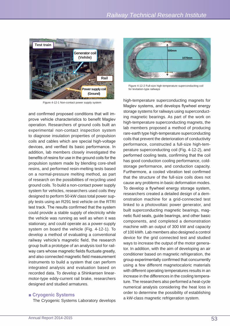
and confirmed proposed conditions that will im-prove vehicle characteristics to benefit Maglev operation. Researchers of ground coils built an experimental non-contact inspection system to diagnose insulation properties of propulsion coils and cables which are special high-voltage devices, and verified its basic performance. In addition, lab members closely investigated the benefits of resins for use in the ground coils for the propulsion system made by blending core-shell resins, and performed resin-melting tests based on a normal-pressure melting method, as part of research on the possibilities of recycling used ground coils. To build a non-contact power supply system for vehicles, researchers used coils they designed to perform 50-kW class total power sup-ply tests using an R291 test vehicle on the RTRI test track. The results confirmed that the system could provide a stable supply of electricity while the vehicle was running as well as when it was stationary, and could operate as a power-supply system on board the vehicle (Fig. 4-12-1). To develop a method of evaluating a conventional railway vehicle’s magnetic field, the research group built a prototype of an analysis tool for rail-way cars whose magnetic fields fluctuate greatly, and also connected magnetic field measurement instruments to build a system that can perform integrated analysis and evaluation based on recorded data. To develop a Shinkansen linear-motor-type eddy-current rail brake, researchers designed and studied armatures.
■ Cryogenic SystemsThe Cryogenic Systems Laboratory develops
Test train
Generator coil(Vehile)
Rail
Power supply coil(Ground)
Figure 4-12-1 Non-contact power supply system high-temperature superconducting magnets for Maglev systems, and develops flywheel energy storage systems for railways using superconduct-ing magnetic bearings. As part of the work on high-temperature superconducting magnets, the lab members proposed a method of producing rare-earth type high-temperature superconducting coils that prevent the deterioration of conductivity performance, constructed a full-size high-tem-perature superconducting coil (Fig. 4-12-2), and performed cooling tests, confirming that the coil has good conduction cooling performance, cold-storage performance, and conduction capacity. Furthermore, a cooled vibration test confirmed that the structure of the full-size coils does not cause any problems in basic deformation modes. To develop a flywheel energy storage system, researchers created a detailed design of a dem-onstration machine for a grid-connected test linked to a photovoltaic power generator, and built superconducting magnetic bearings, mag-netic fluid seals, guide bearings, and other basic components, and completed a demonstration machine with an output of 300 kW and capacity of 100 kWh. Lab members also designed a control device for the grid connected test and studied ways to increase the output of the motor genera-tor. In addition, with the aim of developing an air conditioner based on magnetic refrigeration, the group experimentally confirmed that concurrently using a few different magnetocaloric materials with different operating temperatures results in an increase in the differences in the cooling tempera-ture. The researchers also performed a heat-cycle numerical analysis considering the heat loss in order to determine the possibility of establishing a kW-class magnetic refrigeration system.
500mm
1070mm
Figure 4-12-2 Full-size high-temperature superconducting coil for levitation-type railways
Railway Technical Research Institute
53Annual Report 2014-2015

and communication specifications to permit the use of sea bottom seismograph data to provide railways with early warnings (Fig. 4-13-1). As part of research on huge earthquakes, the Lab pro-posed a method of predicting tsunami waveforms near shorelines by applying observed tsunami waveforms and tsunami propagation proper-ties, coastal tsunami height prediction method incorporating small-scale tsunami simulations, and a method of estimating earthquake motion by considering the extent of faults and local ground amplification. To estimate earthquake motion and earthquake damage with high precision, it has begun to perform highly concentrated earthquake observations and to explore underground struc-tures along railway lines.
■ Soil Dynamics and Earthquake Engineering
The Soil Dynamics and Earthquake Engineering Lab conducts basic and applied research on the ground behavior against earthquakes everything from the basic properties of earthquake motion to its impact on the ground when an earthquake occurs and also establishes seismic design stan-dard. In order to evaluate the behavior during an earthquake, it developed an earthquake damage simulator in cooperation with other concerned labs. It has developed a new method of efficiently
13 Center for Railway Earthquake Engineering Research
The Center for Railway Earthquake Engineering Research consists of three laboratories, namely, Seismic Data Analysis, Soil Dynamics and Earthquake Engineering, and Structural Dynamics and Response Control Labs, which are responsible for earthquake-related research and development consulting work and contract testing work.
In FY2014, considering the possibility of an earthquake occurring directly under Tokyo or a huge subduction-zone earthquake, which are now feared to be imminent, the Centre worked on soft-countermeasure technologies by developing an early earthquake alarm system and proposing an instantaneous tsunami estimation method. It also conducted research and development on hard countermeasure technologies, for example, by proposing new structures and mechanisms such as a liquefaction prevention method with vine-like ground improvement, a super-connected foundation viaduct or a negative stiffness damper. The Centre also verified the precision of the rail-way earthquake disaster simulator, which was built as a tool in the event of an earthquake to quickly hypothesize the kinds of potential disaster risks and their locations, confirming the practical-ity of the simulator.
■Seismic Data AnalysisThe Seismic Data Analysis Lab undertakes
research and development to improve early earthquake warning capabilities, to provide in-stantaneous predictions of tsunamis and strong earthquake motion when a large earthquake occurs, and to estimate earthquake motion and damage with high precision in order to achieve early restoration of railway services. With the aim of improving early earthquake warn-ing capabilities, the Lab developed a seismograph that incorporates a new P-wave based earthquake specification estimation algorithm and a noise discrimination method. It proposed a processing method
Direction of progress
Damage display capable of confirming damage location and degree of damage
Residual deformation indication
Shear failure indication
Figure 4-13-2 Example of the results of an earthquake damage simulation
Sea bottom seismograph data Information for alarms
(Continuous wave form ) (Index/quality control information)
Undersea cable
Sea bottom seismograph
At sea On land
Index calculationQuality controlinformation
Alarm decision
Railway company
Figure 4-13-1 Alarm processing flow when using sea bottom seismograph
Research and Development
54 Annual Report 2014-2015

friction is manifested at the same time as when the friction causes damping during an earthquake. The Lab confirmed that this can reduce stiffness of an overall structural system, and that on a rigid frame viaduct with normal specifications, the device can reduce absolute displacement by as much as 20%.
modelling both ground and structures in order to easily make predictions over a wide area and a method of appropriately visualizing the results obtained by this new method (Fig. 4-13-2). It has also worked to improve the applicability of the simulator. It has also verified the simulator by using actual seismic damage cases to show that the results provided by this simulator are extremely precise.
■ Structural Dynamics and Response Control
The Structural Dynamics and Response Control Lab works to clarify phenomena of the seismic behavior of structures, power poles, vehicles etc. and develops sophisticated methods to evaluate their behavior. It has conducted research and development of seismic design methods and seismic retrofitting work methods. To evaluate the behavior of structures, it has measured the damping constants of about 90 railway structures to clarify their properties. It also clarified the fact that the damping properties of a structure are more strongly correlated with its natural frequency than with its structural form to propose a damp-ing constant evaluation method. Based on the research on seismic retrofitting, it developed a negative stiffness friction damper as a new seis-mic isolation device. As shown in Figure 4-13-3, this device is so constructed that by using a gas spring to cause high pressure contact of a convex plate and sliding material, the stabilized negative
PTFE)
1780mm
652m
m
Direction of motion Gas spring
Sliding material
Convex sliding plate
Figure 4-13-3 Negative stiffness friction damper
Railway Technical Research Institute
55Annual Report 2014-2015

Report on Key Activities under the Previous Master Plan RESEARCH 2010
Executive Summary1disasters as well as energy issues.
In addition, as overseas deployment of Japanese railway technologies has gathered mo-mentum, RTRI’s Railway International Standards Center has intensified activities aimed at propos-ing international railway standards prepare by Japan. Simultaneously RTRI promoted joint research with foreign research institutes and dispatched its researchers to the counterpart organizations.
As an example of RTRI’s management efforts, since RTRI became a public interest incorporated foundation on April 1, 2011, the Institute has been exhaustively improving operation under a new management system, intensifying compliance, fostering human resources, and upgrading and renewing test equipment.
RTRI has formulated a new vision that clearly indicates its ambition and direction toward the future and a new master plan – RESEARCH 2020 – for five years beginning in fiscal 2015.
The Railway Technical Research Institute (RTRI) steadily carried out the master plan - RESEARCH 2010 – for five years after fiscal 2010 and accomplished most of expected purposes while carrying out related R&D activities and other business activities and operations.
In tackling this R&D, RTRI set up the “objec-tives of R&D” to indicate the direction of R&D and the “pillars of R&D” to specify R&D themes to focus on. RTRI concentrated its efforts on further sophistication of simulation technology as a chal-lenge in a new field.
During the period of RESEARCH 2010, Japan happened to suffer the Great East Japan Earthquake and some local heavy rains. Consequently, the public came to have stronger awareness of security and safety as well as energy issues, which lead to the change in the environment surrounding the Japanese society and railways. To cope with this change, RTRI aggressively tackled R&D activities related to earthquakes and other large-scale natural
2Business Activities
2.1 Public interest services
2.1.1 Research and developmentRTRI defined as its R&D objectives
“Improvement of Safety,” “Harmony with the Environment,” “Cost Reduction,” and “Improvement of Convenience.” To pursue these objectives effectively while preventing dispersion of limited resources, the Institute set up three pillars as specific targets: “R&D for the future of
railways,” “development of practical technologies,” and “basic research for railways.” Consequently, it implemented 694 themes spending 13.9 billion yen for R&D activities (Tables 1 and 2).
In order to sophisticate the simulation technol-ogy, RTRI newly established a specialty division to be in charge of large-scale computing. For this purpose, it introduced a new supercomputer featuring almost 10 times faster processing speed than its predecessor. To make R&D more
56 Annual Report 2014-2015

efficient, comprehensive partnership was estab-lished with the Institute of Industrial Science, the University of Tokyo, while actively implementing joint researches and contract researches with domestic and foreign universities and other re-search institutes. In addition, the Institute made the best use of occasions such as R&D reviews where RTRI’s researchers could receive advice
Category FY 2010 FY 2011 FY 2012 FY 2013 FY 2014 FY2010 – FY2014
R&D for the future of railways
34 44 62 45 37 79
Development of practical
technologies140 134 109 111 108 310
Basic researches for railways
124 123 111 115 135 305
Total 298 301 282 271 280 694
Table 1: The Number of Projects Implemented in Each Fiscal Year (unit: a number of projects)
Category FY 2010 FY 2011 FY 2012 FY 2013 FY 2014 Total
R&D for the future of railways
5 7 10 10 9 43
Development of practical technologies
12 10 6 7 8 45
Basic researches for railways
10 10 8 9 11 50
Total 29 28 25 27 29 139
Table 2: R&D Expenses (before-tax prices in 100 million yen)
Note: Due to fraction processing, totals may not equal the sum of individual figures. Expenses of separately commissioned projects are excluded.
and undergo assessments from outside persons of learning and experiences who were chosen as research advisors for RTRI.
Major results of R&D were disclosed to the public through periodical publication, technical forums, lectures etc., and results of completed projects were made public in the form of brochures.
57Annual Report 2014-2015
Railway Technical Research Institute

Report on Key Activities under the Previous Master Plan RESEARCH 2010
(Safety improvement against derailment and collision)
RTRI developed a bogie whose wheel load decrease is controlled by adopting movable structure for the bogie frame so that wheels could follow track irregularity. By integrating an assist steering system, the derailment quotient could be reduced by up to 50% in comparison with conventional bogies in a running test conducted in RTRI’s premises. In addition, taking into ac-count the passenger injury severity, the Institute invented a simulation technique of reproducing vehicle conditions at the time of an accident, which should be used as an evaluation method of vehicle crashworthiness, by using a detailed analysis model of human bodies and car bodies, including their interior materials. Simultaneously, the Institute proposed a limit value of the integral calculation of vehicle impact acceleration to be used as an index for prevention of passengers’ serious injuries.
(Safety improvement against weather disasters)RTRI developed a hazard mapping technology
to display on the Geographic Information System (GIS) such risks along railway lines as landslide disasters, strong wind disasters, and avalanche hazards and rockslide disasters. This technol-ogy was realized by developing a local weather numeric simulation method that could reproduce climatic phenomena around railway lines in a spatial resolution of 250 m and by constructing an evaluation technique of slope failure during rainfall time that could almost perfectly reproduce a state of collapse in a real disaster and then by integrating the method and the technique with a method of evaluating a risk of a rockslide disaster.
(Safety improvement against earthquakes) Targeting at large-scale earthquakes, RTRI
built a method of predicting main-shock and aftershock motions of magnitude 8 or stronger earthquakes. Compared with conventional meth-ods, this method realized a significant increase in prediction accuracy; for example, when applied to the Great East Japan Earthquake, it could predict instrumental seismic intensity almost within a level range of ±1. In addition, the Institute enhanced accuracy of the simulation method of reproducing
(1) R&D for the future of railwaysRTRI positioned as targets of R&D for the fu-
ture of railways (1) technology development items that would have a large spillover effect when they are put into practical use, (2) elucidation of phenomena that would promise a drastic break-through in R&D, and (3) items for basic research such as building of tools. And then, the Institute decided five major items and 12 individual items that constituted the major ones, and eventually total 79 themes were implemented.
1) Improvement of safety and reliability of railway system(Improvement of safety and reliability by intelligent train)
RTRI built a prototype of an intelligent train system to support drivers with reinforced sens-ing, communications, and information processing functions. This system consists of (1) high-precision position detecting technology, (2) bogie abnormality detection technology, (3) route infor-mation (such as conditions of ground facilities) transmitting/receiving and storing technology, and (4) driver support technology that can provide in-formation needed for safe operation, etc. For the position detecting function, new equipment was developed by introducing a tachometer generator, an acceleration sensor, etc. as components so as to detect positions within an error of several meters. In terms of the bogie abnormality detec-tion, newly developed equipment could, by itself, judge abnormalities of bogies, such as hunting motion and a bearing loss, based on vibration and temperature and determine a degree of danger, and then transmit the information to an on-board system. In addition, the Institute developed a sleepiness degree detector that focused on the face of a driver through a camera as well as a forward monitoring device. Furthermore, by integrating these devices and pieces of equip-ment, the Institute prototyped a system that could decide a safe speed and a stop position, display information in a manner that could prevent confu-sion of a driver, and perform drive intervention in the event of an emergency.
58 Annual Report 2014-2015

motions of vehicles and overhead contact line poles observed during an earthquake. RTRI also built a method of evaluating remaining bearing force of structures observed after receiving large external force, and proposed new viaduct struc-ture that could reduce earthquake response by connecting and integrating the foundations under the ground.
2) Enhanced energy efficiency(Energy consumption reduction of vehicles)
RTRI developed an induction motor whose power loss was reduced by up to 30% as a result of change in material and structure of the rotor, and it also made clear the effect of changing shapes and layouts of the rooftop and underfloor equipment in reducing air resistance. By these efforts, energy consumption could be reduced by 10% or so. In addition, the Institute developed an algorithm to find out a pattern of coasting and braking which minimizes the energy consumption , and it also developed a simulator that could pro-duce a running curve based on the algorithm. In the test runs following the running curve produced by the simulator, the energy saving effect reached up to 4%.
(New power supply system)RTRI proposed a new power supply system
where renewable energy-based generating equipment and a power storage facility are combined and a method to control the system, and it built a system to stabilize power supply by coordinating fluctuations in generated power and power consumption by electric rolling stock operation. As a technology to efficiently provide power, RTRI succeeded in using superconduc-tive feeding cables laid 300 meters in RTRI’s premises to make vehicles run. In addition, in order to stabilize the power supply by reducing regeneration cancellation, RTRI manufactured a flywheel equipped with a superconductive magnet bearing which has an electric storage capacity of 100 kWh. Furthermore, the Institute developed an operation power simulator that could predict an influence of power supply from various sources and train operation on power consumption within an error of about 2%.
3) Maintenance innovation(New condition-based maintenance technology)
RTRI produced a prototype to detect abnor-mal states of ground facilities by continuously monitoring state changes in the long and medium terms. A monitoring system of bridge conditions uses information from acceleration sensors and displacement sensors to monitor state changes of bridge columns, foundation, and beams. The Institute made test installation and operation of a system equipped with functions to efficiently collect the data from the sensors by radio. Other systems RTRI developed are a system to monitor track irregularity using an inclination angle sen-sor; a system to monitor turnout-rail wear through images taken by a stereo camera mounted on a vehicle bogie; a system to monitor and detect abnormal conditions of overhead contact wire by measuring contact force of pantographs, etc.
(Innovation of structure renovation technology)RTRI developed a repair/reinforcement method
of viaduct intermediate slabs whose implementa-tion costs could be reduced by about 20% from costs of conventional construction methods, a beam reinforcement method, an interval expan-sion method between pillars to expand the space under a viaduct, and so on. The Institute also developed, as a construction technique to ex-pand the space of an underground train station, a new connection method applied to new and old subway structures that could reduce costs by almost 10% from conventional methods and, as a technology to improve safety and amenity in the space of elevated stations, an engineering method to adopt a light membrane roof for an elevated station platform.
4) Maintaining and developing railway networks (Evaluation and measures for internal amenity)
RTRI proposed a ride-comfort evaluation method that matched bodily sensation of pas-sengers, where longitudinal, lateral and vertical vibrations were simultaneously taken into account. It also developed a variable-attenuation vertical damper and a horizontal vibration control device together with a method of reducing vibration to a level where riding comfort could be secured
59Annual Report 2014-2015
Railway Technical Research Institute

Report on Key Activities under the Previous Master Plan RESEARCH 2010
through simultaneous control of two or more modes of vibration. Moreover, a vehicle body tilting mechanism with the maximum tilt angle of 5 degrees was developed for a pendulum vehicle to increase vibration ride comfort and reduce travel sickness. RTRI proposed an index for evalua-tion of internal noise, taking into consideration a degree of discomfort of passengers against noise. The Institute also proposed divided floor plates and application of microporous panels to ceiling boards as a technique to reduce internal noise.
(Evaluation of the environment along railway lines and measures for high-speed operation)
RTRI created a technique to estimate strength of aerodynamic sound generated from bogies by conducting a wind-tunnel test using an ap-proximately 1/7-scale model vehicle. With this technique, it became possible to separately estimate the aerodynamic noise from the lower part of vehicles and the rolling noise. As a result, with this technique, the degree of contribution by each noise source can be estimated and the data can be used to estimate the effects of noise reduction measures. RTRI developed the wind-load reduction type of noise insulation device that could be opened under the strong wind to reduce loads on existent structures; moreover, the Institute developed a sound insulating-material for rail joints. It also built a simulation method to predict vibrations of the ground and buildings along railway lines by taking into consideration the impacts of passing vehicles.
(Transition facilitation at junctions)RTRI proposed a method to quantitatively as-
sess convenience provided by routes for transfer between buses and trains, and it also developed a simulation method to predict a passenger flow though inner-city traffic, including abnormal situa-tions such as transport disorder, while identifying bottleneck stations in intercity traffic and trains expected to be converged on by passengers. Furthermore, the Institute developed a simula-tor to recapture running of trains using the train performance curve it worked out for this purpose, and then produced a system to evaluate opera-tion plans from a viewpoint of improvement of convenience for passengers and energy-saving
effect.
5) Building a railway simulator (Design and development of the railway simulator core system)
RTRI built a prototype of a virtual railway test track to analyze dynamic mutual interaction among structures, tracks, and vehicles and that between overhead contact wire and pantographs, where a trainset was running. It was confirmed that the vehicle acceleration obtained by the simu-lation with a trainset model had an error of 1% or less to the acceleration of a real train’s running on the RTRI’s test track. It was also confirmed in a large-scale structure/wheel interaction model that the stress at the wheel/rail contact point had an error of 10% or less to that obtained from a theoretical formula. In the model of conditions between overhead contact wire and pantographs, it was confirmed that the vertical movement of a pantograph had an error of 10% or less to mea-sured values.
In addition, RTRI developed a seismic hazard simulator to predict earthquake motion propaga-tion from the epicenter to a given point along a railway track and seismic damage to structures which may be generated there. It also developed another simulator to predict aerodynamic noise and the airflow around a pantograph through large-scale calculation based on an orthogonal grid method. It was confirmed that the seismic hazard simulator presented the seismic intensity on the ground level that had 10% or less errors to values observed during the Great Hanshin Earthquake; and the prediction simulator of the airflow around a pantograph showed that its error to the wind-tunnel experiment data could become 10% or less by increasing the number of grids.
(2) Development of practical technologiesRTRI responded timely and appropriately to
various requirements from JR companies and implemented total 310 themes, including the research topics of RTRI’s researchers’ own choice that met needs of railway operators and, at the same time, had higher priority in RTRI’s R&D, in addition to designated topics that could contribute to solution of problems in the actual railway operation.
60 Annual Report 2014-2015

1) Improvement of safetyIIn the “development of an earthquake early
warning system using sophisticated alarm al-gorithm,” RTRI created an algorithm that could enhance prediction precision of earthquake factors using the P wave and then developed a prototype seismometer in which the algorithm was used. Currently, a verification test is going on, aiming at the mass production. And, it also pro-posed a new method of sending alerts based on data collected from ocean-bottom seismographs.
In the “development of a method to reinforce masonry walls combining landslide prevention netting and rock mass reinforcement materials,” RTRI proposed a seismic strengthening method in order to prevent collapse of masonry walls during an earthquake. This method combines protective netting which is easy to install and ground reinforcement materials. In addition, RTRI worked out a related design manual.
In the “development of an interview technique to analyze the background factors of an accident,” RTRI developed an interview technique to be used by accident investigators of train operation companies as well as an educational program to teach the technique; consequently it was con-firmed that it was effective in helping the survey respondents express their views more actively on the situations and background of errors.
2) Harmony with the environmentIn the “development of a reducing method of
micro-pressure wave,” RTRI invented a hood with inside partition to be installed at the tunnel exits in order to reduce micro-pressure wave gener-ated by Shinkansen trains running at ever higher speeds. Its effect has been confirmed by model experiments. This type of a hood can be installed at locations where a longer tunnel entrance hood cannot be installed.
3) Cost reduction
In the “development of an integral bridge using reinforced soil,” RTRI developed a new structure form characterized by higher seismic resistance at the joint area connecting a bridge and embank-ment, a weak point in the structure, This type of structure was realized by integrating reinforced embankment and a bridge. After confirmation
of sufficient strength using a test bridge, it was applied to real bridges.
4) Improvement of convenienceIn the “practical application of the new silicon
buffer for freight train,” RTRI developed a buffer featured by excellent shock absorbing perfor-mance and durability in order to prevent collapse of cargo on container wagons caused by their longitudinal motion. It was confirmed in running tests that this buffer could reduce longitudinal vibration motion of a running train. Accordingly, a verification test of durability has started with com-mercial vehicles, aiming at practical application.
(3) Basic researches for railwaysIn the field of basic research which is to be the
starting point and foundation of practical technolo-gies RTRI has put higher priority on the four items, that is, (1) sophistication of the simulation technol-ogy, (2) analysis of degradation and deterioration, (3) enhancement of evaluation technology, and (4) human factors. Including research on the Maglev, magnetically levitated train technology and its application to conventional railways, the Institute implemented total 305 projects.
1) Improvement of safety
In the “elucidation of rainfall resistance of earth structure after an earthquake,” RTRI built an analysis method to evaluate the influence of rain water which flows into cracks generated by earthquake motions and conducted a model experiment and a validation analysis using a real embankment, which elucidated the mechanism of after-quake decrease in the embankment rainfall resistance. In this study, the amount of decrease was also quantitatively measured.
In the “ analysis of large-scale soil deformation using particle method,” RTRI built a simulation method for modeling soil and water in the form of particles, evaluating complicated deformation behavior of the ground and groundwater, and fi-nally reproducing large-scale ground deformation phenomena such as a slope failure, soil liquida-tion and debris flow.
In the “efficient learning method for finger-pointing and call,” RTRI produced a software for personal computers to learn that finger-pointing
61Annual Report 2014-2015
Railway Technical Research Institute

Report on Key Activities under the Previous Master Plan RESEARCH 2010
and call are effective in preventing human errors. Using this software, RTRI designed a learning method which enables drivers to actually feel its effects. As a result, about 700 drivers admitted its effects in human error prevention and safety training.
2) Harmony with the environmentIn the “waveform predicting method of micro-
pressure wave,” RTRI improved a simulation method of predicting a compression wave that was formed when a train rushed into a tunnel and thus enhanced prediction accuracy of a micro-pressure wave emitted from the other mouth of a tunnel. As a result, the calculation errors to the results of field tests were reduced approximately to one-third.
In the “improvement of evaluation technology of the inductive interference analysis,” RTRI proposed a technique to predict electromagnetic noise generated from underfloor devices of vehi-cles by calculating noise levels of electric current flowing through traction motor wires with reference to vehicle specifications. With this technique, it became possible to predict electromagnetic noise from underfloor devices of vehicles at the stages of designing and manufacturing. Previously such noise had been measured only on completed vehicles.
3) Cost reductionIn the “functional improvement of pantographs
by use of control technology,” RTRI proposed an active control technology of Shinkansen train pantographs in order to enhance current collec-tion performance without extensively upgrading overhead contact wire equipment. Meanwhile, it was confirmed that this technology could reduce fluctuation in contact force with overhead contact wire by almost 70%.
4) Improvement of convenienceIn the “study of practical application of linear rail
brake,” RTRI designed and made a prototype of a linear motor type of eddy-current brake system for high-speed vehicles that could be operated using self-generated power even during power outage and could provide braking force without contact with rails. Subsequently, the Institute mounted
this prototype on a test vehicle to successfully confirm that it could provide braking force as designed.
2.1.2 InvestigationRTRI conducted investigations to search new
R&D challenges toward the future, and eventually selected issues such as sophistication of railway disaster-mitigation technology, etc. The Institute also set up a dedicated group in charge of strategic investigation in fiscal 2011, promoting investiga-tions to comprehend mid- and long-term social and technological trends with a focus on specific fields related to railways such as safety, environ-ment, and traffic economy. Some of investigation results were later adopted as R&D themes. And these results were publicized through the RTRI Technical Forum and its journal RTRI Report .
2.1.3 Technical Standard ServicesRTRI worked out three categories of drafts
including seismic-resistant design standards and tunnel design standards, while implementing nine survey and research items such as evaluations of car body rolling displacement and a magnetic field in a vehicle. In addition, RTRI prepared 25 design support tools, including design calculation examples related to technical standards.
2.1.4 Information ServiceTechnical information regarding railwaya
was actively collected and stored from vari-ous domestic and overseas sources, including documents, magazines, standards, and other materials. Meanwhile, RTRI’s R&D activities and the results were made open to the public through periodicals and its websites. RTRI continued its efforts to digitize its collections and the results of its research and development so as to improve the collections of its electronic library.
2.1.5 Publishing and TrainingRTRI has been issuing periodicals “RTRI
Report,” “RRR,” “Quarterly Reports of RTRI (QR),” and “Information on World-Wide Railway Technologies (WRT).” Contents of RRR under-went renovation to be further enriched. Moreover, RTRI held RTRI Lectures for timely themes such as “Towards Further Improvement of Railways,”
62 Annual Report 2014-2015

Monthly Presentations to publicize the research results, and Railway Technical Seminars to provide training courses and disseminate technologies. RTRI also organized the RTRI Technology Forum at the Kunitachi Institute and in Osaka to publicize results and contents of R&D activities directly to parties concerned with railways.
2.1.6 Diagnosis and ConsultingRTRI handled 2,147 cases of consulting
Category FY 2010 FY 2011 FY 2012 FY 2013 FY 2014 Total
Consulting (Equipment failures,
disasters, etc.)
380(58)
390(42)
443(53)
482(46)
452(51)
2,147(250)
Table 3: Consulting Case Numbers (unit: a number of cases)
services, meeting the requests by railway op-erators and other parties concerned (Table 3). Among them, 250 cases were related to cause investigations into accidents, vehicle troubles, and ground facility malfunctions, proposals of countermeasures, and support for post-disaster recovery. And other 1,897 cases were concerned with technical guidance (including lending of equipment and sending RTRI’s experts) to solve problems related to railway technology.
2.1.7 International Standard ServicesRTRI tackled activities related to inter-
national railway standards in a strategic manner. Responding to Japan’s proposals, the International Electrotechnical Commission (IEC) issued international standards of the on-board primary linear induction motor, the condenser for power electronics, and the transmission system in a trainset based on Ethernet and published technical specifications of the wireless train con-trol system. The Commission also discussed an on-board electric power storage system and other two technical matters. The International Organization for Standardization (ISO) issued the international standards of materials of syn-thetic sleepers, as Japan proposed, and actively discussed railway project plans and vehicle air conditioning systems.
2.1.8 QualificationsRTRI held the accreditation test for Professional
Railway Design Engineers in Tokyo and Osaka. The number of examinees was 3,750 in total and that of successful applicants was 674. The Institute also renewed its status as a test-ing agency authorized by the Minister of Land, Infrastructure, Transport and Tourism, extending the expiry date of the status for five more years. In addition, in fiscal 2012, it extended the valid term of the first stage examination certificate from
one year to three years for the convenience of examinees.
2.1.9 Railway Technology Promotion Center RTRI communicated closely with railway and
tramway operators and regional railway associa-tions to grasp common technical needs, while promoting R&D, diagnosis and consulting, infor-mation services, and other types of business in addition to technical standards services.
In the business field of R&D, RTRI took on 17 research and study projects and already completed 11, including “the study of measures against lightning damage on signal equipment.” In diagnosis and consulting, the Institute responded to 406 inquiry cases regarding technical issues in its effort to support local railway operators, while providing onsite advice in 11 cases and conducting onsite investigations in 48 cases. In information services, RTRI’s Database System on Railway Accidents was additionally equipped with a function of railway accident search by cause in fiscal 2014. RTRI also issued a new training material for mid-level engineers, that is, the fifth edition of “Railway Technology to Learn from Accidents.” It also held lectures on themes such as energy conservation in two to four venues every year, and also delivered lectures total 38
63Annual Report 2014-2015
Railway Technical Research Institute

Report on Key Activities under the Previous Master Plan RESEARCH 2010
times at technical committees of regional railway associations and on other occasions.
2.1.10 Railway International Standards CenterRTRI set up the Railway International Standards
Center in April 2010 to concentrate its deliberations of international railway standards on the Center, and simultaneously deployed strategic activities to introduce Japanese technical specifications and design concepts into international standards. The Institute secured a leading position in ISO/TC 269 (Railway Applications), set up in April 2012, because the Institute had been involved in management of the Technical Committee from an early stage and one of its staff assumed the office of chairman of the Committee. Furthermore, RTRI promoted information sharing with European and Asian standards organizations, and contributed to human resources development in Japan through organizing seminars.
2.1.11 International Activities RTRI continued joint research with SNCF (
French National Railways), RSSB (the Railway Safety and Standards Board) of the UK, CARS (China Academy of Railway Sciences) and KRRI (Korea Railroad Research Institute), and started new joint studies with DB Systemtechnik GmbH (DBST), the French Institute of Science and Technology for Transport, Development and Networks (IFSTTAR), the Politecnico de Milano, etc. The Institute implemented total 47 joint research projects with universities and research organizations in Europe and Asia, and sent 20 researchers to these organizations on a long-term basis (Table 4). It also held the 10th International Workshop on Railway Noise (IWRN10) in Nagahama and another international workshops on study ballasted-track maintenance and wheel/rail damage.
RTRI participated in various international conferences for presentations and information exchange. RTRI has been a member of the organizing committee of the World Congress on Railway Research (WCRR) over years and supported the management of WCRR2011, WCRR2013, and WCRR2016. Moreover, as part of its international activities, it organized research
forums and technical seminars in order to expand technology exchanges with Asian countries. RTRI also gathered and shared information on current states of railways and high-speed railway projects in each country .
2.1.12 Tohoku-Pacific Ocean Earthquake CountermeasuresIn the wake of the Great East Japan Earthquake
that occurred in March 2011, RTRI made field observations and provided technical guidance for recovery in response to requests of railway operators. The Institute joined a subcommittee of the Investigation and Examination Committee created by East Japan Railway Company to analyze behaviors of vehicles and electrification poles at the time of the Earthquake, and became a member of some advisory councils set up by the Ministry of Land, Infrastructure, Transport and Tourism. As RTRI’s support for recovery/reconstruction works of railways from damage by the Earthquake, the “Technical Proposals for Recovery/Reconstruction of Railways” was com-piled to offer immediately applicable technologies that were mainly developed by RTRI .
2.2 Profit-making business
Railway operators, independent administrative agencies, and other parties placed orders to RTRI for a contract research concerning installation of an urgent earthquake detection system, surveys and researches of construction of new Shinkansen lines, R&D for gauge change trains, and so on, resulting in total 2,706 business contracts that produced an income of 14.8 billion yen.
To promote business, vigorous quality control procedures such as a customer satisfaction sur-vey were implemented, and sales activities were intensified , for example, by holding a technology exchange conference. Other efforts were also made to make business activities more efficient and enhance staff’s awareness of income and expenditure management.
64 Annual Report 2014-2015

Name Country ThemeStarting
Year
Rai
lway
ope
rato
r/Ins
titut
e
CARS (China Academy of Railway Sciences)KRRI (Korea Railroad Research Institute)
China
Republic of Korea
(Japan-China-ROK joint study)Standardization of electromagnetic compatibility (EMC) and other 14 themes
1992
SNCF(Société Nationale des Chemins de fer Français)
France(Japan-France joint research)Energy saving system and other 13 themes
1995
RSSB(Railway Safety and Standard Board)
UK(Japan-UK joint research)Recurrent checks on railway sites and other three themes
2008
SBB(Swiss Federal Railways) Switzerland Optimization of transport planning and
operating method 2011
DBST(DB Systemtechnik GmbH) Germany Micro-pressure waves 2014
IFSTTAR(French Institute of Science and Technology for Transport, Development and Networks)
France Reinforced soil technique 2014
Uni
vers
ity
Chalmers University of Technology Sweden Rolling contact fatigue and other two
themes 2010
Massachusetts Institute of Technology US
Magnetic-field property of high Tc superconductive equipment and other two themes
2010
University of Bristol UK High-precision thrust control with a number of actuators 2012
Cambridge University UK Adaptation of a monitoring technique for civil structures 2012
Columbia University US Seismic design of earth structures 2013
Newcastle University UK Passenger injury evaluation at the time of a train collision 2014
Politecnico di Milano ItalyDynamic interaction between vehicles and track structures on a long-span railway bridge
2014
Table 4: Participant Universities and Institutes in Joint Researches
2.3 Commissioned R&D projects
The Government entrusted RTRI with inves-tigative research of technical standards while independent administrative agencies placed
some tasks such as a slope stability assessment in RTRI’s charge, resulting in total 35 R&D cases that produced an income of 1.24 billion yen. The total revenue was 16.1 billion yen, covering profit-making business and R&D projects entrusted by the Government.
65Annual Report 2014-2015
Railway Technical Research Institute

Report on Key Activities under the Previous Master Plan RESEARCH 2010
3.1 Compliance, etc.
RTRI established the Compliance Promotion Office in July 2010 where rules and procedures were formulated and the reporting contact office and the consultation window were set up. The Institute strengthened its compliance system and improved research ethics by conducting staff training, preparing handbooks, disseminating compliance information, and encouraging staff to do self-learning through an RTRI version of e-learning system.
To reinforce the information management sys-tem, RTRI reviewed its management method and information handling, which resulted in abolition of current rules and establishment of new informa-tion management rules that were announced to all the RTRI staff members for strict observance.
To make RTRI’s office and facilities safer and more convenient for work, the Institute took nec-essary measures to enhance staff’s awareness of safety issues and streamline work environment.
3.2 Human Resources and Personnel
RTRI was engaged in its business with the number of its personnel kept around 530 every fiscal year as per the Master Plan (Table 5).
Specifically, RTRI added to its payroll 86 new staff members to prevent a fault in technology succession, employed 11 experienced workers as
mid-career hiring, and rehired 47 old and retired staff for technology succession. In response to the amendment of the Law Concerning Stabilization of Employment of Older Persons, the Institute reformed its system so as to make those who wanted to continue work in RTRI after age-limit retirement eligible for continued employment. In addition, working patterns in RTRI became more multifaceted, where work-life balance was taken into consideration, with introduction of a short-time working scheme and expansion of child-care leave.
At the start of fiscal 2012, those employed after the launch of JR accounted for more than 80% of all the RTRI staff, so that a focus was set on the inheritance of technologies with introduc-tion of OJT practices to address the generation change. As a new initiative, RTRI systematized its education program by renovating contents of stratified education training. In order to develop researchers who are experienced in actual train operation and capable of doing research which directly meets rail operators’ needs, RTRI has provided various training opportunities to its em-ployees in and out of the institute and promoted personnel-exchanges with JR companies.
3.3 Organizations
The Railway International Standards Center and the Compliance Promotion Office were set up in fiscal 2010.
3Management
FY 2010 FY 2011 FY 2012 FY 2013 FY 2014
Actual number 530 540 540 534 534
Plan 530 530 530 530 530
Table 5:PNumber of employees (unit:person)
Note: Each figure in the upper row shows an actual number at the start of each fiscal year.
66 Annual Report 2014-2015

In addition, the Signaling & Transport Information Technology Division was founded in fiscal 2012 to intensify and streamline the R&D system aiming at active use of ICT. The Center for Railway Earthquake Engineering Research was founded in fiscal 2014 as a base to concen-trate and conduct earthquake-related research activities, provide technical guidance and per-sonnel training concerning earthquake-resistant measures, and deliver restoration support at the time of earthquake, in order to raise the speed and efficiency in the research into earthquake issues.
Moreover, a new research laboratory, Computational Mechanics, was set up in the Railway Dynamics Division in fiscal 2012 in order to focus on developing, maintaining, and enhanc-ing advanced simulation technology,
3.4 Facilities
As for test facilities, RTRI’s rolling stock test facilities were renovated to conduct vehicle tests more stably and hunting motion tests at high speeds more safely. Further introduction and improvement of RTRI’s unique facilities were car-ried out, including the axle fatigue test machine to study in a real-size setup a process of cracks
generated on an axle progressing and resulting in a break; the structure loading test equipment to implement loading experiments of civil structures where experimentation was linked to a numeric analysis; and the load and rolling test equipment to assess performance of the car-body tilting system and a control method of it.
Concerning general facilities, RTRI applied safety measures and aseismic reinforcement work to experiment facilities, while installing solar power generation devices as a global en-vironmental measure and renovating obsolete equipment.
3.5 Balance of Payments
On the income side, the income for shared services was total 65.8 billion yen, exceeding a planned value by 3.6 billion yen. The amount of total cash subsidies, including a government grant, was 3.6 billion yen.
As for expenditure, RTRI spent total 1.48 billion yen for R&D, an increase by 3 billion yen over a planned value due to increase in money grants. Payments for purchase of fixed assets were 3 billion yen, 500 million yen over a plan due to renovation of the rolling stock test equipment and so on.
4Vision of RTRI and Next Term’s Master Plan
RTRI formulated a new vision, “RISING – We will develop innovative technologies to enhance the rail mode so that railways can contribute to the creation of a happier society.,” which orients RTRI’s aspiration and future advancement, in order to respond without delay to the changing society and diversifying needs, create high-quality results, and thereby meet expectations of the railroad industry and society.
In fiscal 2015 a new five-year master plan “RESEARCH 2020 -Aiming at creation of innova-tive technologies” was launched.
67Annual Report 2014-2015
Railway Technical Research Institute

YEAR 2014-2015: April 1, 2014 - March 31, 2015Copyright© 2015 Railway Technical Research Institute.All rights reserved.Published by Fuminao OKUMURA, Executive Director
International Division, Railway Technical Research InstituteHikari-cho 2-8-38, Kokubunji-shi, Tokyo 185-8540 JAPAN
Find us :WEB: http://www.rtri.or.jp/eng/index.htmlFacebook: https://www.facebook.com/rtri.eng
For download :Brochure & Annual Report: http://www.rtri.or.jp/eng/rtri/brochure.htmlRailway Technology Newsletter:http://www.rtri.or.jp/eng/publish/newsletter/index.html
68 Annual Report 2014-2015
