annual report 2008 - continuous casting...
TRANSCRIPT

ANNUAL REPORT 2008UIUC, August 6, 2008
Zhaohui Yuan(MS Student)
Department of Mechanical Science and Engineering
University of Illinois at Urbana-Champaign
Thermal distortion of a slab mold with
cavity for electromagnetics
University of Illinois at Urbana-Champaign • Metals Processing Simulation Lab • BG Thomas 2
Acknowledgements
• Continuous Casting Consortium Members
• National Center for Supercomputing Applications (NCSA) at UIUC
• HKS (ABAQUS)
• Mr. Kim From POSCO provides blueprints for the model with electromagnetic brake
• Other Graduate students, especially Lance Hibbeler and Lyric Shi
University of Illinois at Urbana-Champaign • Metals Processing Simulation Lab • BG Thomas 3
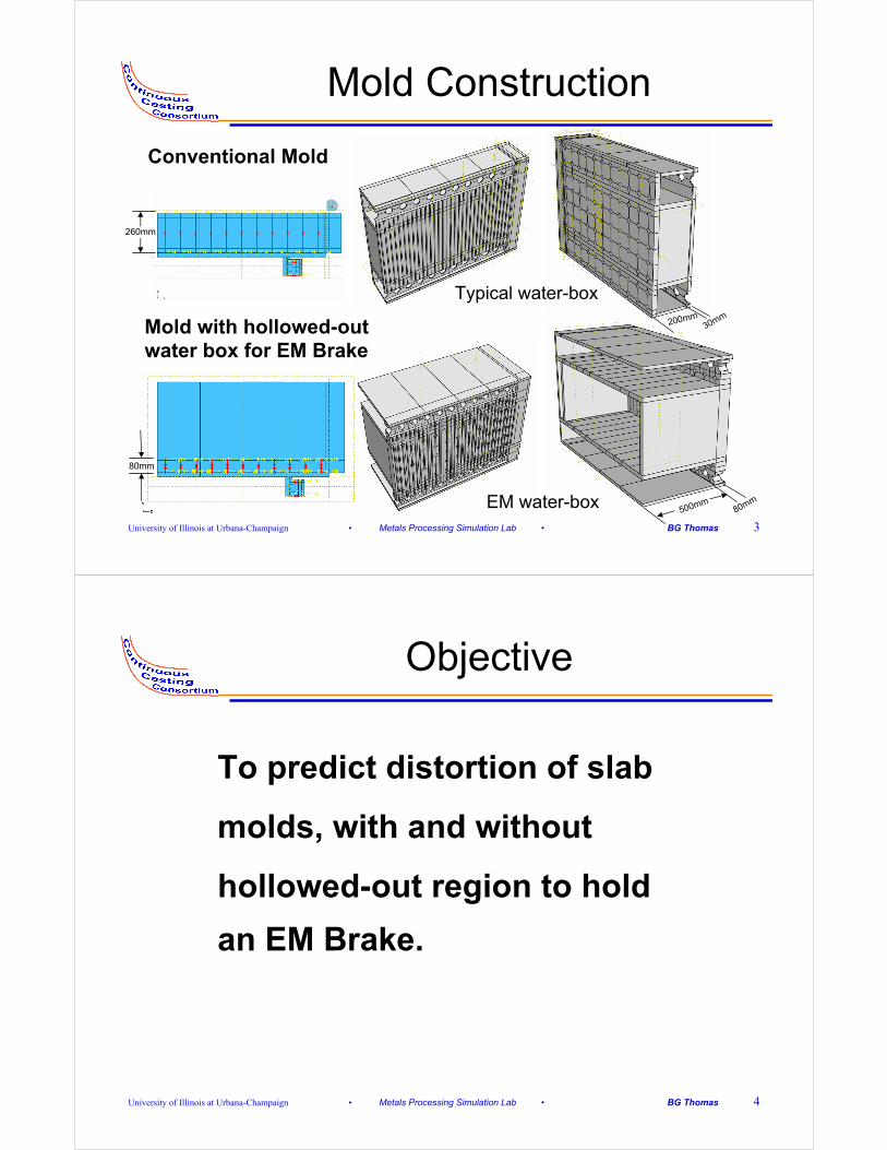
Mold Construction
Conventional Mold
Mold with hollowed-out water box for EM Brake
Typical water-box
EM water-box
200mm30mm
500mm80mm
80mm
260mm
University of Illinois at Urbana-Champaign • Metals Processing Simulation Lab • BG Thomas 4
Objective
To predict distortion of slab
molds, with and without
hollowed-out region to hold
an EM Brake.
University of Illinois at Urbana-Champaign • Metals Processing Simulation Lab • BG Thomas 5
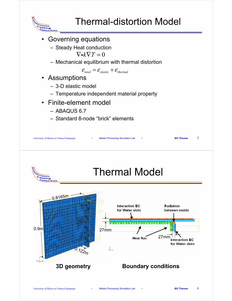
• Governing equations– Steady Heat conduction
– Mechanical equilibrium with thermal distortion
• Assumptions– 3-D elastic model
– Temperature independent material property
• Finite-element model– ABAQUS 6.7
– Standard 8-node “brick” elements
Thermal-distortion Model
0k T∇ ∇ =i
total elastic thermalε ε ε= +
University of Illinois at Urbana-Champaign • Metals Processing Simulation Lab • BG Thomas 6
Thermal Model
3D geometry Boundary conditions
27mm
0.8165m
27mm
0.122m
0.9m

University of Illinois at Urbana-Champaign • Metals Processing Simulation Lab • BG Thomas 7
Heat flux down mold
0 0.1 0.2 0.3 0.4 0.5 0.6 0.7 0.80
0.5
1
1.5
2
2.5
3
Hea
t flu
x (M
W/m
2)
Distance below meniscus(m)
Heat flux for this project
Li, C. and B.G. Thomas, "Analysis of the Potential Productivity of Continuous Cast Molds", The Brimacombe Memorial Symposium, (Vancouver, Canada, October 1-4), G. Irons & A. Cramb, eds., Canadian Institute of Mining, Metallurgy, and Petroleum, Montreal, Canada, 2000, pp. 595-611
University of Illinois at Urbana-Champaign • Metals Processing Simulation Lab • BG Thomas 8
Stress Model
3D geometry Boundary conditions

University of Illinois at Urbana-Champaign • Metals Processing Simulation Lab • BG Thomas 9
Mold Geometries
University of Illinois at Urbana-Champaign • Metals Processing Simulation Lab • BG Thomas 10
Material Properties and Operation Conditions

University of Illinois at Urbana-Champaign • Metals Processing Simulation Lab • BG Thomas 11
Compare with previous work
Thomas, B.G., G. Li, A. Moitra and D. Habing, "Analysis of Thermal and Mechanical Behavior of Copper Molds during Continuous Casting of Steel Slabs", Iron and Steelmaker (ISS Transactions), Iron and Steel Society, Warrendale, PA, Vol. 25, No. 10, 1998, pp. 127
30
3027
200mm
122mm
816.5mm
27
96
University of Illinois at Urbana-Champaign • Metals Processing Simulation Lab • BG Thomas 12
Heat Flux Comparison
0 0.1 0.2 0.3 0.4 0.5 0.6 0.7 0.80
0.5
1
1.5
2
2.5
3Heat flux profile
Hea
t flu
x (M
W/m
2)
Distance below meniscus(m)
Heat flux for this project
Heat flux used in the paperBG Thomas, 1998

University of Illinois at Urbana-Champaign • Metals Processing Simulation Lab • BG Thomas 13
Temperature Comparison
BG Thomas et al", ISS Transactions, 1998.
University of Illinois at Urbana-Champaign • Metals Processing Simulation Lab • BG Thomas 14
Distorted Shape Comparison
-1.6 -1.4 -1.2 -1 -0.8 -0.6 -0.4 -0.2 00
0.1
0.2
0.3
0.4
0.5
0.6
0.7
0.8
0.9Distortion at mold interface
Dis
tanc
e fr
om m
old
bott
om (
m)
Distortion of interface (mm)
Wide face
Narrow face
Meniscus
BG Thomas et al", ISS Transactions, 1998.

University of Illinois at Urbana-Champaign • Metals Processing Simulation Lab • BG Thomas 15
Model Validation
• Similar geometry and similar heat flux profile.
• Similar temperature contours.
• Higher heat flux near the meniscus results in a higher maximum temperature.
• Similar distortion.
• New wide face distorts more due to larger width.
• Similar gaps between WF and NF at top and bottom;
• Conclusion: New model is valid and can be used for further study.
University of Illinois at Urbana-Champaign • Metals Processing Simulation Lab • BG Thomas 16
Thermal Model
0 100 200 300 400 500 6000
0.1
0.2
0.3
0.4
0.5
0.6
0.7
0.8
0.9Narrow face temperature distribution
Dis
tanc
e fr
om m
old
bott
om (
m)
Temperature (mm)
meniscus
x=0 (center)
x=0.0339mx=0.061m
x=0.1046m
x=0.122m
0 50 100 150 200 250 300 350 400 450 5000
0.1
0.2
0.3
0.4
0.5
0.6
0.7
0.8
0.9Wide face temperature distribution
Dis
tanc
e fr
om m
old
bott
om (
m)
temperature( C)
z=0 (center)z=0.3474m
z=0.55m
z=0.7183m
z=0.8165m
z=0.8911mz=1.1m
Narrow Face Wide Face
Maximum temperature of the model

University of Illinois at Urbana-Champaign • Metals Processing Simulation Lab • BG Thomas 17
Thermal Model
• The highest temperature in each mold is just below meniscus.
• The maximum temperature in the whole model is at the edge narrow face just below the meniscus (owing to gap that forms between NF and WF).
University of Illinois at Urbana-Champaign • Metals Processing Simulation Lab • BG Thomas 18
Narrow Face Stress Analysis
-0.2 -0.1 0 0.1 0.2 0.3 0.4 0.5 0.60
0.1
0.2
0.3
0.4
0.5
0.6
0.7
0.8
0.9Narrow face displacement perpendicular to mold
Dis
tanc
e fr
om m
old
bott
om (
m)
Displacement (mm)
x=0 (center)
x=0.0339m
x=0.061mx=0.1046m
x=0.122m

University of Illinois at Urbana-Champaign • Metals Processing Simulation Lab • BG Thomas 19
Narrow Face Stress Analysis
• All the curves have a peak just below the meniscus (owing to the temperature peak)
• Bolts tend to lessen distortion: cause minimums in the distortion profile.
• More bolts and even distribution would reduce the distortion
• More bolts and even distribution would reduce the stress (the maximum stress is 1.51GPa, causing yielding of the copper)
University of Illinois at Urbana-Champaign • Metals Processing Simulation Lab • BG Thomas 20
Narrow Face Shape
-0.2 -0.1 0 0.1 0.2 0.3 0.4 0.5 0.60
0.1
0.2
0.3
0.4
0.5
0.6
0.7
0.8
0.9Narrow face displacement perpendicular to mold
Dis
tanc
e fr
om m
old
bott
om (
m)
Displacement (mm)
mold hot face
mold cold facewater jacket surface
meniscus
Gap

University of Illinois at Urbana-Champaign • Metals Processing Simulation Lab • BG Thomas 21
Narrow Face Gap
-0.1 -0.05 0 0.05 0.1 0.15 0.2 0.25 0.3 0.35 0.40
0.1
0.2
0.3
0.4
0.5
0.6
0.7
0.8
0.9Narrow face gap
Dis
tanc
e fr
om m
old
bott
om (
m)
gap (mm)
gap
meniscus
University of Illinois at Urbana-Champaign • Metals Processing Simulation Lab • BG Thomas 22
Narrow Face Shape
• Gap forms between the narrow face mold and water box.
• Water box thickness increases due to temperature increase, which stretches the bolts.
University of Illinois at Urbana-Champaign • Metals Processing Simulation Lab • BG Thomas 23
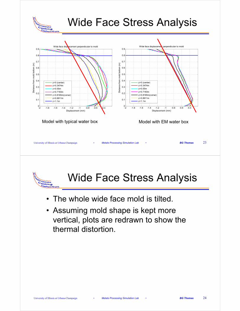
Wide Face Stress Analysis
-2 -1.8 -1.6 -1.4 -1.2 -1 -0.8 -0.6 -0.40
0.1
0.2
0.3
0.4
0.5
0.6
0.7
0.8
0.9Wide face displacement perpendicular to mold
Dis
tanc
e fr
om m
old
bott
om (
m)
Displacement (mm)
z=0 (center)z=0.3474m
z=0.55m
z=0.7183m
z=0.8165m(corner)
z=0.8911mz=1.1m
-2 -1.8 -1.6 -1.4 -1.2 -1 -0.8 -0.6 -0.40
0.1
0.2
0.3
0.4
0.5
0.6
0.7
0.8
0.9Wide face displacement perpendicular to mold
Dis
tanc
e fr
om m
old
bott
om (
m)
Displacement (mm)
z=0 (center)z=0.3474m
z=0.55m
z=0.7183m
z=0.8165m(corner)
z=0.8911mz=1.1m
Model with typical water box Model with EM water box
University of Illinois at Urbana-Champaign • Metals Processing Simulation Lab • BG Thomas 24
Wide Face Stress Analysis
• The whole wide face mold is tilted.
• Assuming mold shape is kept more vertical, plots are redrawn to show the thermal distortion.

University of Illinois at Urbana-Champaign • Metals Processing Simulation Lab • BG Thomas 25
Distorted shape after tilted
-0.8 -0.6 -0.4 -0.2 0 0.2 0.4 0.60
0.1
0.2
0.3
0.4
0.5
0.6
0.7
0.8
0.9adjusted wide face distortion
Dis
tanc
e fr
om m
old
bott
om (
m)
Displacement (mm)
z=0 (center)z=0.3474m
z=0.55m
z=0.7183m
z=0.8165m(corner)
z=0.8911mz=1.1m
-0.8 -0.6 -0.4 -0.2 0 0.2 0.4 0.60
0.1
0.2
0.3
0.4
0.5
0.6
0.7
0.8
0.9adjusted wide face distortion
Dis
tanc
e fr
om m
old
bott
om (
m)
Displacement (mm)
z=0 (center)z=0.3474m
z=0.55m
z=0.7183m
z=0.8165m(corner)
z=0.8911mz=1.1m
Model with typical water box Model with EM water box
University of Illinois at Urbana-Champaign • Metals Processing Simulation Lab • BG Thomas 26
Distorted shape after tilted
• Mold for EM Brake has less distortion!
• The thicker the water box plate is, the more rigid, and less it bends.
• The shorter the bolts are, the harder for them to elongate.
• A thicker plate and shorter bolts will lead to a flatter mold (less distortion).

University of Illinois at Urbana-Champaign • Metals Processing Simulation Lab • BG Thomas 27
Wide Face Shape
-1.8 -1.6 -1.4 -1.2 -1 -0.8 -0.6 -0.40
0.1
0.2
0.3
0.4
0.5
0.6
0.7
0.8
0.9Wide face distortion
Dis
tanc
e fr
om m
old
bott
om (
m)
Distortion (mm)
mold cold face
water box surfacemeniscus
-1.3 -1.2 -1.1 -1 -0.9 -0.8 -0.7 -0.6 -0.5 -0.4 -0.30
0.1
0.2
0.3
0.4
0.5
0.6
0.7
0.8
0.9Wide face distortion
Dis
tanc
e fr
om m
old
bott
om (
m)
Distortion (mm)
mold cold face
water box surfacemeniscus
Model with typical water box Model with EM water box
University of Illinois at Urbana-Champaign • Metals Processing Simulation Lab • BG Thomas 28
Wide Face Shape
• No gap for the wide face model with typical water box
• Constraints will not change the edge shape, just lead to transportation and rotation;
• Gap exists in the wide face mold model for the EM brake. Because the water box plate is too thick to bend.
• thick water box plate has both good and bad effects.
University of Illinois at Urbana-Champaign • Metals Processing Simulation Lab • BG Thomas 29
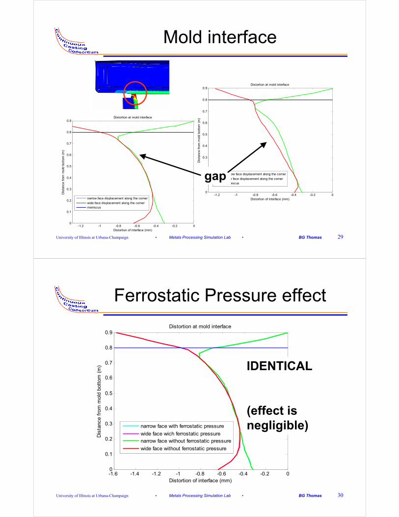
Mold interface
-1.2 -1 -0.8 -0.6 -0.4 -0.2 00
0.1
0.2
0.3
0.4
0.5
0.6
0.7
0.8
0.9Distortion at mold interface
Dis
tanc
e fr
om m
old
bott
om (
m)
Distortion of interface (mm)
narrow face displacement along the corner
wide face displacement along the cornermeniscus
-1.2 -1 -0.8 -0.6 -0.4 -0.2 00
0.1
0.2
0.3
0.4
0.5
0.6
0.7
0.8
0.9Distortion at mold interface
Dis
tanc
e fr
om m
old
bott
om (
m)
Distortion of interface (mm)
narrow face displacement along the corner
wide face displacement along the cornermeniscus
gap
University of Illinois at Urbana-Champaign • Metals Processing Simulation Lab • BG Thomas 30
Ferrostatic Pressure effect
-1.6 -1.4 -1.2 -1 -0.8 -0.6 -0.4 -0.2 00
0.1
0.2
0.3
0.4
0.5
0.6
0.7
0.8
0.9Distortion at mold interface
Dis
tanc
e fr
om m
old
bott
om (
m)
Distortion of interface (mm)
narrow face with ferrostatic pressure
wide face wich ferrostatic pressurenarrow face without ferrostatic pressure
wide face without ferrostatic pressure
IDENTICAL
(effect is negligible)

University of Illinois at Urbana-Champaign • Metals Processing Simulation Lab • BG Thomas 31
Constraints
-1.6 -1.4 -1.2 -1 -0.8 -0.6 -0.4 -0.2 00
0.1
0.2
0.3
0.4
0.5
0.6
0.7
0.8
0.9Distortion at mold interface
Dis
tanc
e fr
om m
old
bott
om (
m)
Distortion of interface (mm)
narrow face with contact
wide face wich contactnarrow face with constraints
wide face with constraints
Two restricted points
University of Illinois at Urbana-Champaign • Metals Processing Simulation Lab • BG Thomas 32
Mold Interface
• The gap is not caused by the ferrostaticpressure
• Constraints will not change the shape of the interface.
• The achieve the balance, the mold must rotate to get the two points to contact.
University of Illinois at Urbana-Champaign • Metals Processing Simulation Lab • BG Thomas 33
Conclusions• Water box for EM brake has thicker plate, shorter bolts and
longer frame, which leads to less distortion.
• Evenly distributed bolts could better limit mold distortion, as well as derive a flatten surface and avoid stress concentration.
• Enough bolts should be assigned to avoid stress concentration.
• The thickness of the water box plate will greatly influent the mold distortion. A thicker plate would lead to a flatter mold.
• Gap might exist at the middle region of the corner, not only at the top and bottom.
• Depending on the water box structure and bolt distribution, gap may be created between the mold and water box.