announcements tuesday’s lecture next week is cancelled –october 18 th assignment 4 is active,...
Post on 21-Dec-2015
214 views
TRANSCRIPT

Announcements
• Tuesday’s Lecture next week is cancelled– October 18th
• Assignment 4 is active, due in my mailbox by 5pm Friday (October 14th)
• Mid-term Thursday, October 27th

Project Dates• Project Description - one paragraph, plus circuit diagrams and web links –
email to me by Tuesday Nov 1st• Guidelines and a few useful links are here:
http://www.physics.udel.edu/~jholder/Phys645/Lab/Projects.htm . There are many more sites if you search the web (e.g. google “hobby electronics”)
• Kits are allowed, but circuits must be assembled on the prototyping board. $50 maximum budget.
• Once approved, I will need a complete parts list, with digikey or radioshack catalog part numbers. I will place the orders, but FINDING THE CORRECT COMPONENTS AND GETTING THEM IN TIME IS YOUR RESPONSIBILITY!!! Note that most basic components (resistors, capacitors etc.) are available in the lab.
• The project should (ideally) contain both analog and digital • You should work with your lab partner, but individual reports are required
for the projects.• The project counts for 20% of your final grade (I grade them)• I will leave copies of some good past projects in the lab (please don’t take
them away)

Lecture 12 Overview
• Op amp circuits– amplifiers– Adding/ Subtracting– Integrating Circuit– Differentiating Circuit– Active Filters

Recap: Opamps
• DC coupled, very high gain, differential amplifier.• Feed part of the output back into the inverting
input to get stable operation in the linear amplification region
• Golden rules under negative feedback:• The voltage at the inputs is the same (v+=v-)• No current flows into the opamp (i+=i-=0)

Op amp circuit 2: Inverting Amplifier
SS
Fout
F
out
S
S
F
out
S
S
FS
inFS
vR
Rv
R
v
R
v
R
vv
R
vv
ii
iii
00
0
• Signal and feedback resistor, connected to inverting (-) input.
• v+=v- connected to ground
S
F
S
out
R
R
v
vGain
0 vvv+ grounded, so:

Op amp circuit 3: Summing Amplifier
SNSN
FS
S
FS
S
Fout
F
out
SN
SN
S
S
S
S
FN
vR
Rv
R
Rv
R
Rv
R
v
R
v
R
v
R
v
iiii
.....
.....
.....
22
11
2
2
1
1
21
• Same as previous, but add more voltage sources
)...( 21 SNSSS
Fout vvv
R
Rv
SSNSS RRRR ... If 21

Summing Amplifier Applications• Adds signals from a number of waveforms• Applications - audio mixer• http://wiredworld.tripod.com/tronics/mixer.html
• Can use unequal resistors to get a weighted sum• For example - could make a 4 bit binary - decimal converter• 4 inputs, each of which is +1V or zero• Using input resistors of 10k (ones), 5k (twos), 2.5k (fours) and 1.25k (eights)

Op amp circuit 4: A non-inverting amplifier
• Feedback resistor still to inverting input, but no voltage source on inverting input (note change of current flow)• Input voltage to non-inverting input
vv FS ii
F
out
S R
vv
R
v
0
S
F
S
out
SS
Fout
S
Fout
R
R
v
v
vR
Rv
vR
Rv
1Gain
1
1

Op amp circuit 5: Differential Amplifier (subtractor)
021 ii
)( 121
2
221
2
21
1
vvR
Rv
vvRR
Rv
vv
R
vv
R
vv
out
out
Useful terms: • if both inputs change together, this is a common-mode input change• if they change independently, this is a normal-mode change • A good differential amp has a high common-mode rejection ratio (CMMR)

Differential Amplifier applications• Very useful if you have two inputs corrupted with the same noise
• Subtract one from the other to remove noise, remainder is signal
• Many Applications : e.g. an electrocardiagram measures the potential difference between two points on the body
The AD624AD is an instrumentation amplifier - this is a high gain, dc coupled differential amplifier with a high input impedance and high CMRR (the chip actually contains a few opamps)
http://www.picotech.com/applications/ecg.html

Op-amp integrator

Op-amp integrator

Integrator Application: Ramp Generator
Integrator response to a constant voltage:VIN
VOUT
tThis is a ramp generator - very useful in timing circuits...
V
V• What's the integrator response to a square wave?

Integrator Application: Ramp Generator
Integrator response to a constant voltage:VIN
VOUT
t
t
This is a ramp generator - very useful in timing circuits...
• ...Useful for waveform generators:
V
V
VIN
VOUT
• What's the integrator response to a square wave?

What does this do?

Op-amp differentiator
dt
dvCRtv
dt
dvC
R
v
ii
SSFout
SS
F
out
SF
)(

Differentiator
• Differentiator response to a square wave?:

Differentiator Application: edge detection
• Differentiator response to a square wave?:
• The differentiator is good at detecting edges, or transitions - very useful in digital circuits.
VIN
VOUT
t
N.B. Don't confuse the differentiator with a differential amplifier (subtractor)!

Other "mathematical operator" circuits can be
easily constructed:
• Logarithm
• Antilogarithm
• Multiplier
• Divider
• Square root function
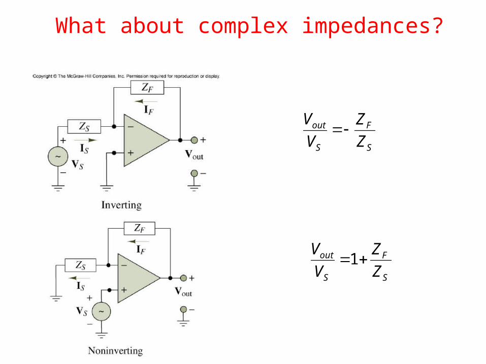
What about complex impedances?
S
F
S
out
Z
Z
V
V
S
F
S
out
Z
Z
V
V1

Active low-pass filter
FF
SF
FF
FF
FFF
S
F
S
out
CRj
RRjA
CRj
RZ
CjRZ
Z
Z
V
VjA
1
/)(
1
1111
)(
e.g. RF/RS=10; 1/RFCF=1
Max Amplification: RF/RS
Low pass factor: 1/(1+ jωRFCF)Cut-off frequency (-3dB = 1/√2)when ωRFCF=1, ie ω0=1/RFCF

Active high-pass filter
SS
S
F
SS
F
SSS
S
F
S
out
CRjR
R
CjR
RjA
CjRZ
Z
Z
V
VjA
11
1
1)(
1
)(
e.g. RF/RS=10; 1/RFCF=1
Max Amplification: RF/RS
High pass factor: 1/(1+ 1/jωRSCS)Cut-off frequency: ωRFCF=1

Active band-pass filter
Combine the two:
)1)(1()(
SSFF
SF
CRjCRj
CRjjA
Advantages of active filters: 1)no inductors (large, pick-up)2)buffered (high input impedance, low output impedance) – so filter performance independent of source and load; can cascade filters