announcement of opportunity - emits …emits.sso.esa.int/emits-doc/esrin/l3_vega_news/l3...esa...
TRANSCRIPT
ESA UNCLASSIFIED - For Official Use
Prepared by Renato Lafranconi
Reference VG-AO-0-C-30001-ESA Issue/Revision 1/0 Date of Issue 13/02/2017
ANNOUNCEMENT OF OPPORTUNITY FOR THE LAUNCH OF MULTIPLE LIGHT SATELLITES ON A VEGA FLIGHT

ESA UNCLASSIFIED - For Official Use
Page 2/9 Issue Date 13/02/2017 Ref
Table of contents:
1 ACRONYMS ............................................................................................... 3
2 INTRODUCTION ........................................................................................ 3
3 DESCRIPTION OF THE OPPORTUNITY .................................................... 4
3.1 General .............................................................................................................................. 4
3.2 Spacecraft classes .............................................................................................................. 4
3.3 Orbital parameters ............................................................................................................ 5
3.4 Requirements and constraints .......................................................................................... 5
4 SELECTION PROCEDURE ......................................................................... 5
4.1 General scheme ................................................................................................................. 5
4.2 Pre-selection criteria .........................................................................................................6
4.3 Responses to the Announcement of Opportunity ............................................................6
ANNEX 1: TECHNICAL AND OPERATIONAL REQUIREMENTS
ANNEX 2: QUESTIONNAIRE

ESA UNCLASSIFIED - For Official Use
Issue Date 13/02/2017 Ref VG-AO-0-C-30001-ESA
1 ACRONYMS
AO Announcement of Opportunity
FMA Final Mission Analysis
LLL Light Satellite, Low-cost Launch opportunities
LSA Launch Service Agreement
MOU Memorandum Of Understanding
NoI Notice of Intent
PoC Proof of Concept
S/C Spacecraft
SSMS Small Spacecraft Mission Service
2 INTRODUCTION
VEGA is a small launcher developed by ESA composed of three solid propellant stages and a bi- liquid upper stage. The launch system has been designed to carry a 1500 kg Spacecraft on its reference low earth orbit mission (700 km circular polar). The launcher has to date successfully performed all its eight flights.
In 2014 ESA initiated activities to preliminary assess the feasibility of an improved service dedicated to SmallSats to expand the launcher in-orbit capability to ride-share concepts. The Small Spacecraft Mission Service (SSMS) is planned to be ready for a first flight on a Vega launch in the second half of 2018.
VEGA SSMS project is targeted to the definition of VEGA service elements tailored for light satellites, notably: a) adapter and dispenser system structures, mechanisms and avionics; b) mission analysis and launch preparation processes and tools by adaptation of the VEGA standard ones.
The objective of this Announcement of Opportunity is to identify and pre-select Candidate Spacecrafts for a first Vega flight based on SSMS hardware and processes. The selection process is described at chapter 4.
The European Commission adopted on 26 October 2016 the Communication on the Space Strategy for Europe. With the objective of reinforcing Europe's autonomy in access to space, the Commission identified possible areas of action which include supporting research and innovation efforts, in particular to ensure Europe’s ability to react to and anticipate disruptive changes; encouraging the development of commercial markets for new space activities.
ESA UNCLASSIFIED - For Official Use
Issue Date 13 February 2017 Ref VG-AO-0-C-30001-ESA
In this context, and with a view to optimising complementarity, the European Commission joins the present announcement of opportunity (AO) aiming at exploring possible interest and without prejudice to future decisions.
3 DESCRIPTION OF THE OPPORTUNITY
3.1 General This AO is open to any Potential Customer of launch services, with no restriction of nationality, including:
A. Light Satellites operated by or for the benefit of the following entities, irrespective of the launch service procuring entities (hereafter referred to as “European institutional satellites”) :
• ESA,
• the European Union,
• national governments, public entities, agencies and undertakings which arepart of the administration of ESA Member States and/or European UnionMember States,
• European international organisations, other than ESA, which are composed, interms of number of member states, mainly of ESA Member States and/orEuropean Union Member States,
B. Other Light Satellites (commercial)
All potential Customers of launch services for S/C’s of this category are invited to submit their application, as per paragraph 4.3.1 of this document.
3.2 Spacecraft classes The following Spacecraft classes are eligible under this AO:
1. S/C pertaining to the following typical classes in terms of overall mass• Class 4 (including 1U, 3U, 6U): 1Kg – 25Kg• Class 3 (including 12U+): 25.1Kg – 60Kg• Class 2: 60.1Kg – 200Kg• Class 1: 200.1Kg – 400Kg
2. S/C pertaining to the following typical classes in terms of overall volume• Class 4 (including 1U, 3U, 6U): 280x320 mm base, 420 mm height• Class 3 (including 12U+): 600x600x600 mm

ESA UNCLASSIFIED - For Official Use
Issue Date 13 February 2017 Ref VG-AO-0-C-30001-ESA
• Class 2: from 600x660 mm base, 700 mm height to 800x800 mm base, 1200mm height
• Class 1: 1700 mm base diameter, 1800 mm height, or inscribed squared base
3.3 Orbital parameters The reference orbit for the SSMS PoC flight mission is Sun Synchronous Orbit (SSO) in the 500 – 800 km altitude range. Other orbit might be considered within the Vega launch system capability, i.e. any Low Earth Orbit (LEO) in the 400 – 1400 km altitude range.
Potential Customers are therefore requested to explicitly identify, together with their preferred orbit, the flexibility of their spacecraft to the other possible orbits.
3.4 Requirements and constraints Potential Customers shall provide a preliminary compliance matrix versus the technical and operational requirements listed in Annex 1.
In order to properly perform the feasibility analysis and consequently support the definition of possible aggregates of several light satellites, potential customers are required to provide their response to the questionnaire in Annex 2.
Potential Customers shall identify their planned readiness for flight in their response to this AO. The earliest opportunity for the Vega flight is in the second half of 2018.
4 SELECTION PROCEDURE
4.1 General scheme The selection procedure involves two steps:
• STEP 1:
o Issuance of this Announcement of Opportunity with its annexes
o Submission of applications from Potential Customers
o Identification of possible satellite aggregates and pre-selection ofcandidate Spacecraft by ESA with the support of Arianespace and incoordination with EC
o For pre-selected satellites, conclusion of MoU between ESA and thelaunch service procuring entities of the selected spacecrafts

ESA UNCLASSIFIED - For Official Use
Issue Date 13 February 2017 Ref VG-AO-0-C-30001-ESA
• STEP2 undertaken once the coverage of the launch service costs for the selectedaggregate is secured :
o Conclusion of the ESA-Arianespace contract for the undertaking ofthe Vega flight embarking the European institutional satellitesselected by ESA and, where appropriate, by EC.
o Conclusion of Launch Service Agreements between Arianespaceand launch service procuring entities of the selected spacecrafts. [Inthe case of European institutional satellites, the LSA shall becompliant with the relevant MoU of STEP1.]
4.2 Pre-selection criteria
Compatibility with the Technical Constraints, in particular
• Ability to couple the Spacecraft with others• Spacecraft orbital parameters flexibility
Compatibility with the Programmatic Constraints
• Planning (earliest possible and last possible launch date)• Current Spacecraft’s development status• Operability (launch campaign operations, safety aspects…)
Financial contribution
• Customer offer of contribution to the launch service costs
4.3 Responses to the Announcement of Opportunity In response to his AO, the potential Customers are invited to submit by March 31, 2017 a Notice of Intent (NoI) identifying the contact point:
• Name:• Mailing address:• Telephone:• Fax• E-mail:

ESA UNCLASSIFIED - For Official Use
Issue Date 13 February 2017 Ref VG-AO-0-C-30001-ESA
and including the preliminary statement of compliance to the technical requirements (Annex 1) and the filled questionnaire (Annex 2) as requested at paragraph 3.4 of this document.
The applications of all potential Customers are to be delivered to ESA by March 31st, 2017. Any written communication shall be addressed to:
ESA Launchers Directorate
Mr Fabio CARAMELLI SSMS Project Manager ESRIN Via Galileo Galilei, 64 Casella Postale 64 00044 Frascati Italy
Tel.: +39 06 94180646 Fax: +39 06 94180802 Mail: [email protected]
with copy to Mr Renato LAFRANCONI VEGA Exploitation Programme Manager ESRIN Via Galileo Galilei, 64 Casella Postale 64 00044 Frascati Italy
Tel: +39 06 94188832 Fax: +39 06 94180802 Mail: [email protected]
Potential Commercial Customers are invited to send their application also to:
Arianespace
Mr Patrick LOIRE VP Marketing and Business Development Boulevard de l’Europe 91006 Evry-Coucouronnes France Tel: +33 01 60876269 Email: [email protected]
with copy to Mr Marino FRAGNITO VP VEGA Business Unit Boulevard de l’Europe 91006 Evry-Coucouronnes France Tel: +33 01 60876011 60876Email: [email protected]
ESA UNCLASSIFIED - For Official Use
Issue Date 13/02/2017 Ref VG-AO-0-C-30001-ESA
ANNEX 1
TECHNICAL AND OPERATIONAL REQUIREMENTS

Small Spacecraft Mission Service User’s Manual – Proof of Concept flight on
VEGA DC/BD/ST/CDU N17-003
ESA & Arianespace Proprietary Information
Page : i
SMALL SPACECRAFT MISSION SERVICE
USER MANUAL
for
SSMS PROOF OF CONCEPT FLIGHT ON VEGA
Issue 1 Revision 0 / Feb. 2017
The signatures below certify the validity of this document
ARIANESPACE ESA
Prepared by: Claude DUPUIS
Prepared by: Aldo SCACCIA
Approved by:
Approved by : Fabio CARAMELLI

Small Spacecraft Mission Service User’s Manual – Proof of Concept flight on
VEGA DC/BD/ST/CDU N17-003
RECORD OF AMENDMENTS
Issue - Revision
Date Modified Pages AUTHORIZATION
AE ESA 1.0 Feb. 2017 All

Small Spacecraft Mission Service User’s Manual – Proof of Concept flight on
VEGA DC/BD/ST/CDU N17-003
ESA & Arianespace Proprietary Information Page : 3 of 26
TABLE OF CONTENTS
1. Introduction …………………………………………………………………………………… 4
1.1. Purpose of the present User Manual 1.2. Definition, Acronyms and Abbreviations
2. Technical description…………………………………………………………………..…… 6
2.1. SSMS dispenser description 2.2. Small Spacecraft accommodation 2.3. Reference configurations for the SSMS PoC flight
3. Mission requirements ……………………………………………………………………… 11
3.1. Orbit 3.2. Launch time 3.3. Launch sequence, launch duration 3.4. Conditions at S/C separation 3.5. Small Satellite sequence after separation
4. Interface requirements ……………………………………………………………………13
4.1. Interface requirements for Mini satellite (Class#1) 4.2. Interface requirements for Micro satellite (Class#2) 4.3. Interface requirements for Nano satellite (Class#3) 4.4. Interface requirements for Cubesats deployers (Class#4) 4.5. Interface verifications
5. Design requirements, Flight Environment & S/C Qualification …………… 21 5.1. Design requirements for Mini satellite (Class#1) 5.2. Design requirements for Micro satellite (Class#2) 5.3. Design requirements for Nano satellite (Class#3) and Cubesats deployer
(Class#4) 5.4. Flight Environment 5.5. S/C qualification
6. Stack integration & Launch campaign ……………………………………………… 24
6.1. Stack integration flow 6.2. S/C checks/accessibility after Stack integration 6.3. S/C hazardous propellant fuelling after Stack integration

Small Spacecraft Mission Service User’s Manual – Proof of Concept flight on
VEGA DC/BD/ST/CDU N17-003
ESA & Arianespace Proprietary Information Page : 4 of 26
1. Introduction
1.1. Purpose of the present User Manual The present User’s Manual for Small Spacecraft is dedicated to the SSMS PoC flight on VEGA. It is intended to provide basic information for Smalls Passengers on this flight using the SSMS hardware and processes on a Vega launch system operated from the Guiana Space Centre. The content encompasses:
the classification of Small Spacecraft; the SSMS dispenser description; the envisaged mission; the description of the interfaces between Small Spacecraft and Launch Vehicle (LV); the requirements for Small Spacecraft design and verification; the ground operations for stack integration and launch.
Together with the Vega User’s Manual, it gives readers the information to assess the compatibility with the proposed standardized SSMS configurations.

Small Spacecraft Mission Service User’s Manual – Proof of Concept flight on
VEGA DC/BD/ST/CDU N17-003
ESA & Arianespace Proprietary Information Page : 5 of 26
1.2. Definitions, Acronyms and Abbreviations CLA Coupled Loads Analysis CoG Centre of Gravity COTE Check Out Terminal Equipment DUA Demande d’Utilisation Arianespace (Application to use Arianespace Launch vehicles) ESA European Space Agency GSE Ground Support Equipment ICD Interface Control Document LLL Low cost Launch opportunities for Light missions LMP-103S “green” Liquid MonoPropellant LSA Launch Services Agreement LTAN Local Time of Ascending Node LV Launch Vehicle MLB Motorized Light Band MUV Manuel Utilisateur Vega (Vega User’s Manual) N2H4 Hydrazine N/A Non Applicable PoC Proof of Concept PSC Planetary Systems Corporation QSL Quasi Static Loads RfW Request for Waiver S/C Spacecraft SSMS Small Spacecraft Mission Service SSO Sun Synchronous Orbit Stack Small spacecraft + adapters + SSMS dispenser TBC To Be Confirmed TBD To Be Defined UCIF Upper Composite Integration Facility VESPA Vega Secondary Payload Adapter

Small Spacecraft Mission Service User’s Manual – Proof of Concept flight on
VEGA DC/BD/ST/CDU N17-003
ESA & Arianespace Proprietary Information Page : 6 of 26
2. Technical description 2.1. SSMS Dispenser description
The SSMS dispenser has a modular design allowing to aggregate different classes of small spacecraft. It is composed of several modular elements, which are briefly described here below: Tower module
Column Module
Lower Module
The lower module is the common core of the SSMS dispenser. It has a hexagonal part and a platform. Six positions are available on the hexagonal part to accommodate up to 6 very small spacecraft or up to 12 (12U) Cubesats deployers horizontally (“lower module positions”). On the platform, up to four positions are available to accommodate small spacecraft (“Deck 2 position”). Then, two, three of four tower modules can be installed on top of the platform to accommodate small spacecraft (“Deck 1 position”). Similarly, a central column module can be installed to accommodate another bigger small spacecraft (“Top position”). Several heights are available for the central column. The lower module is itself attached to the launcher using the existing 937 conical structure. Note: The SSMS dispenser is in its development phase and the definition of these elements may still evolve.

Small Spacecraft Mission Service User’s Manual – Proof of Concept flight on
VEGA DC/BD/ST/CDU N17-003
ESA & Arianespace Proprietary Information Page : 7 of 26
With these elements, many different Stack configurations can be envisaged:
Piggyback configuration
One (1) Main passenger
Six (6) Nano satellites or Six (6) Cubesats deployers
Constellation configuration
Four (4) identical Micro satellites
Six (6) Nano satellites or Six (6) Cubesats deployers
“FLEXI-3” configuration
One (1) Mini satellite
Three (3) Micro satellites
Six (6) Nano satellites or Six (6) Cubesats deployers
“FLEXI-4” configuration
One (1) Mini satellite
Height (8) Micro satellites
Six (6) Nano satellites or Six (6) Cubesats deployers

Small Spacecraft Mission Service User’s Manual – Proof of Concept flight on
VEGA DC/BD/ST/CDU N17-003
ESA & Arianespace Proprietary Information Page : 8 of 26
2.2. Small Spacecraft accommodation The available accommodation and Launch Service depend on the mass and volume of the Small Spacecraft Passenger. Accommodation dimensions as a function of standard position has been established in relation to S/C classes (see AO).
# Class Mass range Standard Envelope Volume Standard position (Kg) (mm)
1 Mini Satellite 400 – 200 H1800 x L1200 x W1200 Top position
2 Micro Satellite 200 – 60
H1200 x L800 x W800
Top position or
Deck#2 position (FLEXI-3 configuration)
H1100 x L700 x W600
Deck #1 position (FLEXI-4 configuration)
or Deck#2 position (FLEXI-4
configuration)
3 Nano Satellite 60 – 25 H600 x L400 x W300
Deck#1 position (FLEXI-4 configuration)
or Base module position
4 Cubesats Deployer 25 – 1 H530 x L320 x W280
(doors open) Base module position

Small Spacecraft Mission Service User’s Manual – Proof of Concept flight on
VEGA DC/BD/ST/CDU N17-003
ESA & Arianespace Proprietary Information Page : 9 of 26
2.3. Reference configurations for the SSMS PoC flight For the SSMS PoC flight on Vega, the envisaged stack configurations correspond to the so-called FLEXI-3 or FLEXI-4 configurations, allowing to embark up to fifteen (15) Small Spacecraft or Cubesats deployers. The sketches below illustrate the envisaged Stack configurations:
SSMS Stack conf#1 SSMS Stack conf#2
FLEXI 4 configuration with Mini and Micro S/C
FLEXI 4 configuration with Micro S/C
One (1) Mini satellite on a stretched central column Four (4) Micro satellites on Deck#1 on four tower modules Four (4) Micro satellites on Deck#2 Three (3) Nano satellites on Base module Three (3) Cubesats deployers on Base module
One (1) Micro satellite on the central column Four (4) Micro satellites on Deck#1 on four tower modules Four (4) Micro satellites on Deck#2 Three (3) Nano satellites on Base module Three (3) Cubesats deployers on Base module

Small Spacecraft Mission Service User’s Manual – Proof of Concept flight on
VEGA DC/BD/ST/CDU N17-003
ESA & Arianespace Proprietary Information Page : 10 of 26
SSMS Stack conf#3 SSMS Stack conf#4
FLEXI 4 configuration with Mini, Micro and Nano S/C
FLEXI 3 configuration with Micro S/C
One (1) Mini satellite on a stretched central column Four (4) Nano satellites on Deck#1 on four tower modules Four (4) Micro satellites on Deck#2 Three (3) Nano satellites on Base module Three (3) Cubesats deployers on Base module
One (1) Micro satellite on the central column Three (3) Micro satellites on Deck#2 Three (3) Nano satellites on Base module Three (3) Cubesats deployers on Base module
As the modular design of the SSMS dispenser allows a large number of possible combinations, alternative configurations can be also envisaged depending of customer demands. The actual configuration of the SSMS PoC flight on Vega will be frozen following extensive analysis of customer demands.

Small Spacecraft Mission Service User’s Manual – Proof of Concept flight on
VEGA DC/BD/ST/CDU N17-003
ESA & Arianespace Proprietary Information Page : 11 of 26
3. Mission requirements 3.1. Orbit The reference orbit for the SSMS PoC flight mission is Sun Synchronous Orbit (SSO) in the 500 – 800 km altitude range. Other orbit might be considered within the Vega launch system capability, i.e. any Low Earth Orbit (LEO) in the 400 – 1400 km altitude range. Thanks to the reignition capability of the VEGA last stage (AVUM), the small passengers can be separated on up to two different altitudes (with the corresponding inclination for a SSO). The Local Time of Ascending Node (LTAN) can be either 10:30 a.m. or 06:00 a.m. The actual targeted orbit and Local Time of Ascending Node for the SSMS PoC flight will be frozen following SC aggregate definition. 3.2. Launch time For SSO mission, the launch window is reduced to a single launch time. This launch time will be determined taking into account the targeted Local Time of Ascending Node (LTAN). 3.3. Launch sequence, launch duration The overall launch sequence and the separation time of the Small Spacecraft will be determined depending of the passenger mission requirements, of the available ground stations, etc … A typical ascent and separation sequence is the following:
Three-stage ascent, AVUM boost(s) to reach the targeted orbit (orbit #1) of the top position passenger or
Deck#1 passengers, When present, longitudinal separation of the S/C on top position, Avoidance maneuvers, AVUM boosts (as necessary) to reach the targeted orbit (orbit #2) of the Deck#1
and/or Deck#2 passengers, Longitudinal separation of the S/C on Deck#1. It can be a simultaneous separation of
all the S/C or a separation two by two, Avoidance maneuvers (as necessary), Longitudinal separation of the S/C on Deck#2. Similarly to Deck#1, it can be a
simultaneous separation of all the S/C at the same time or a separation two by two. Additionally, when necessary, a tilt can be envisaged (S/C separation axis up to 10° from launcher longitudinal axis),
Avoidance maneuvers (as necessary), Lateral separation of the S/C on Lower module. It can be a simultaneous separation
of all the S/C at the same time or a separation two by two, or a separation three by three,
Avoidance maneuvers,
Small Spacecraft Mission Service User’s Manual – Proof of Concept flight on
VEGA DC/BD/ST/CDU N17-003
ESA & Arianespace Proprietary Information Page : 12 of 26
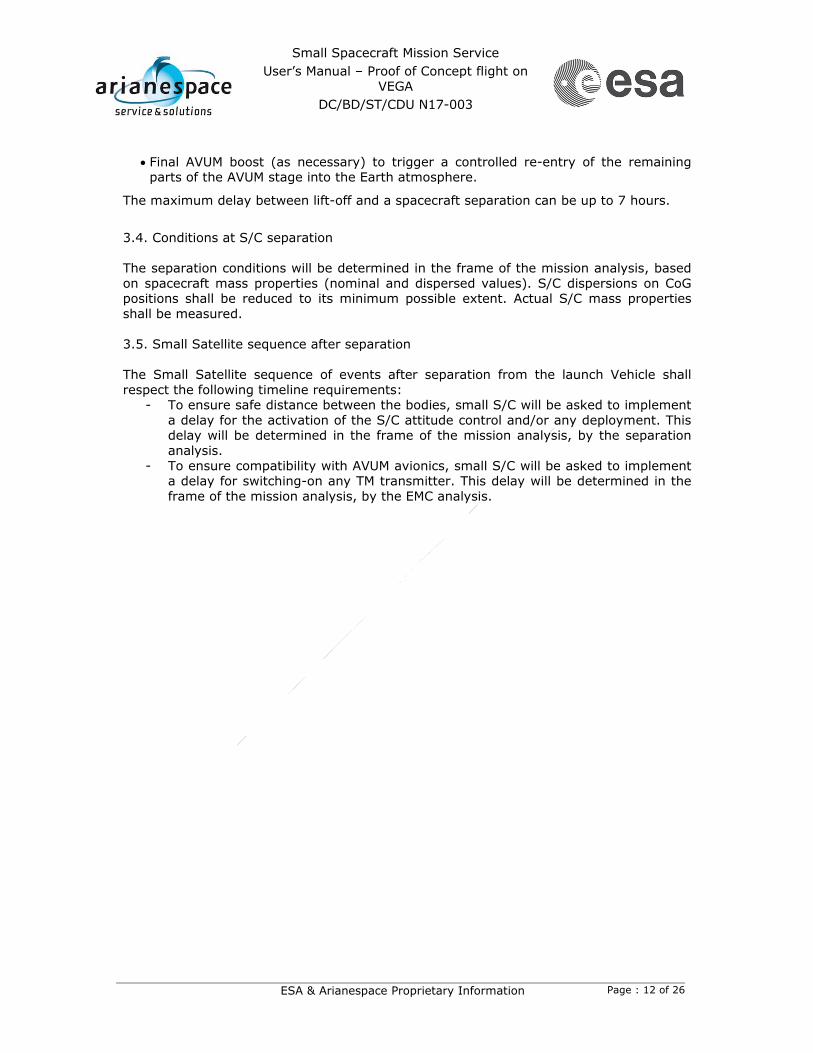
Final AVUM boost (as necessary) to trigger a controlled re-entry of the remaining parts of the AVUM stage into the Earth atmosphere.
The maximum delay between lift-off and a spacecraft separation can be up to 7 hours.
3.4. Conditions at S/C separation The separation conditions will be determined in the frame of the mission analysis, based on spacecraft mass properties (nominal and dispersed values). S/C dispersions on CoG positions shall be reduced to its minimum possible extent. Actual S/C mass properties shall be measured. 3.5. Small Satellite sequence after separation The Small Satellite sequence of events after separation from the launch Vehicle shall respect the following timeline requirements:
- To ensure safe distance between the bodies, small S/C will be asked to implement a delay for the activation of the S/C attitude control and/or any deployment. This delay will be determined in the frame of the mission analysis, by the separation analysis.
- To ensure compatibility with AVUM avionics, small S/C will be asked to implement a delay for switching-on any TM transmitter. This delay will be determined in the frame of the mission analysis, by the EMC analysis.

Small Spacecraft Mission Service User’s Manual – Proof of Concept flight on
VEGA DC/BD/ST/CDU N17-003
ESA & Arianespace Proprietary Information Page : 13 of 26
4. Interface requirements This chapter defined the requirements in terms of usable volume, mechanical interface, electrical interface and interfaces verification. For the SSMS PoC flight on Vega, the S/C-LV interface is based on Lightband system from PSC. Other adapter can be envisaged. 4.1. Interface requirements for Mini Satellite (Class#1) S/C Position Requirement Reference Values Negotiable? Notes
TOP
Usable Static Volume
H 1800 mm 1200 x 1200 mm
yes
Usable volume can be extended up to:
Separation Direction Longitudinal no
S/C hazardous propellant fuelling
Allowed n/a
S/C Mechanical Interfaces Requirement Reference
Values Negotiable? Notes
PSC Mark II Lightband
24-inches
S/C Interface Ring External Diameter 665 mm no
S/C Interface Ring Internal Diameter 589 mm no
S/C Interface Ring mass 1.098 kg ±5% no
Interface screws holes diameter
609.6 mm ± 0.25 mm no
Fasteners type Allen Head cap screws M6 yes
The fastener dimension can be reduced
Tightening torque 11 - 13 Nm yes Minimum admissible torque: 8 Nm
Adjoining surface planarity 0.16 mm yes
Depending on the stiffness of the adjoining structure. The adjoining structure stiffness shall guarantee the planarity in all loads conditions.
PSC Transition Ring (Optional)
24-inches
S/C Transition Ring External Diameter 665 mm TBC no
Optional for flight S/C Transition Ring Internal Diameter 589 mm TBC no
S/C Transition Ring mass TBD no
Interface screws 609.6 mm ± no

Small Spacecraft Mission Service User’s Manual – Proof of Concept flight on
VEGA DC/BD/ST/CDU N17-003
ESA & Arianespace Proprietary Information Page : 14 of 26
holes diameter 0.25 mm
Fasteners type Allen Head cap screws M6 yes
The fastener dimension can be reduced
Tightening torque 11 - 13 Nm yes Minimum admissible torque: 8 Nm
S/C Electrical interfaces Requirement Reference
Values Negotiable? Notes
PSC
Connectors
Number Up to 6 no
Size 15 pins no
Lines available before Stack
integration on LV
Number of Available lines for Class#1 S/C
≤ 74 no
Lines available after Stack
integration on LV (including
countdown phase on launch
pad)
Number of Available lines for Class#1 S/C
≤ 34 yes Depending on Stack configuration

Small Spacecraft Mission Service User’s Manual – Proof of Concept flight on
VEGA DC/BD/ST/CDU N17-003
ESA & Arianespace Proprietary Information Page : 15 of 26
4.2. Interface requirements for Micro Satellite (Class#2) S/C Position Requirement Reference Values Negotiable? Notes
TOP
Usable Static Volume
H 1200 mm 800 x 800 mm
yes
For TOP position, the usable volume can be extended up to:
Deck#2 Separation Direction Longitudinal no
S/C hazardous propellant fuelling
Allowed n/a
The S/C fuelling ports (if needed) accessible after Stack integration i.e. shall be located on one of the S/C faces facing the fairing.
Deck#1
Usable Static Volume
H 1100 mm 700 x 600 mm
Deck#1: yes Deck#2: no
Protrusions out of the usable volume can be negotiated on a case by case basis.
Separation Direction Longitudinal no
For Deck#2 position, a tilt can be envisaged (S/C separation axis up to 10° from launcher longitudinal axis).
Deck#2
S/C hazardous propellant fuelling
Allowed n/a
The S/C fuelling ports (if needed) accessible after Stack integration i.e. shall be located on the S/C face facing the fairing.

Small Spacecraft Mission Service User’s Manual – Proof of Concept flight on
VEGA DC/BD/ST/CDU N17-003
ESA & Arianespace Proprietary Information Page : 16 of 26
S/C Mechanical Interfaces Requirement Reference
Values Negotiable? Notes
PSC Mark II Lightband
13-inches
S/C Interface Ring External Diameter 382 mm no
S/C Interface Ring Internal Diameter 308 mm no
S/C Interface Ring mass 0.576 kg ±5% no
Interface screws holes diameter
330.2 mm ± 0.25 mm no
Fasteners type Allen Head cap screws M6 yes
The fastener dimension can be reduced
Tightening torque 11 - 13 Nm yes Minimum admissible torque: 8 Nm
Adjoining surface planarity 0.09 mm yes
Depending on the stiffness of the adjoining structure. The adjoining structure stiffness shall guarantee the planarity in all loads conditions.
PSC Transition Ring (Optional)
13-inches
S/C Transition Ring External Diameter 382 mm TBC no
Optional for flight S/C Transition Ring Internal Diameter 308 mm TBC no
S/C Transition Ring mass TBD no
Interface screws holes diameter
330.2 mm ± 0.25 mm no
Fasteners type Allen Head cap screws M6 yes
The fastener dimension can be reduced
Tightening torque 11 - 13 Nm yes Minimum admissible torque: 8 Nm
S/C Electrical interfaces Requirement Reference
Values Negotiable? Notes
PSC
Connectors
Number Up to 4 no
Size 15 pins no
Lines available before Stack
integration on LV
Number of Available lines for Class#2 S/C
≤ 60 no
Lines available after Stack
integration on LV (including
countdown phase on launch
pad)
Number of Available lines for Class#2 S/C
≤ 12 yes Depending on Stack configuration

Small Spacecraft Mission Service User’s Manual – Proof of Concept flight on
VEGA DC/BD/ST/CDU N17-003
ESA & Arianespace Proprietary Information Page : 17 of 26
4.3. Interface requirements for Nano Satellite (Class#3) S/C Position Requirement Reference Values Negotiable? Notes
Deck#1
Usable Static Volume
H 600 mm 400 x 300 mm yes
Protrusions out of the usable volume can be negotiated on a case by case basis.
Separation Direction Longitudinal no
S/C fuelling Not Allowed yes
Depending on Stack integration flow. Note: Anyhow, loading of not-hazardous propellant (Xenon for instance) is allowed prior to S/C integration on SSMS dispenser.
LOWER
Module Usable Static Volume
H 600 mm 400 x 300 mm yes
Protrusions out of the usable volume can be negotiated on a case by case basis.
Separation Direction Lateral no
S/C hazardous propellant fuelling
Not Allowed no
Note: Anyhow, loading of not-hazardous propellant (Xenon for instance) is allowed prior to S/C integration on SSMS dispenser.
S/C Mechanical Interfaces Requirement Reference
Values Negotiable Notes
PSC Mark II Lightband
8-inches
S/C Interface Ring External Diameter 255 mm no
S/C Interface Ring Internal Diameter 178 mm no
S/C Interface Ring mass 0.354 kg ±5% no
Interface screws holes diameter
203.2 mm ± 0.25 mm no
Fasteners type Allen Head cap screws M6 (TBC)
yes The fastener dimension can be reduced.
Tightening torque 11 - 13 Nm yes Minimum admissible torque: 8 Nm
Adjoining surface planarity 0.05 mm yes
Depending on the stiffness of the adjoining structure. The adjoining structure stiffness shall guarantee the planarity in all loads conditions.

Small Spacecraft Mission Service User’s Manual – Proof of Concept flight on
VEGA DC/BD/ST/CDU N17-003
ESA & Arianespace Proprietary Information Page : 18 of 26
PSC Transition Ring
8-inches
S/C Interface Ring External Diameter 255 mm TBC no
Optional for flight S/C Interface Ring Internal Diameter 178 mm TBC no
S/C Interface Ring mass TBD no
Interface screws holes diameter
203.2 mm ± 0.25 mm no
Fasteners type Allen Head cap screws M6 (TBC)
yes The fastener dimension is suggested
Tightening torque 11 - 13 Nm yes
S/C Electrical interfaces Requirement Reference
Values Negotiable? Notes
PSC
Connectors
Number Up to 2 no
Size 15 pins no
Lines available before Stack
integration on LV
Number of Available lines for Class#3 S/C
≤ 30 no
Lines available after Stack
integration on LV (including
countdown phase on launch
pad)
Number of Available lines for Class#3 S/C
≤ 12 no

Small Spacecraft Mission Service User’s Manual – Proof of Concept flight on
VEGA DC/BD/ST/CDU N17-003
ESA & Arianespace Proprietary Information Page : 19 of 26
4.4. Interface requirements for Cubesats deployers (Class#4) S/C Position Requirement Reference Values Negotiable? Notes
LOWER
Module
Usable Static Volume
H 530 mm 320 x 280 mm no
Separation Direction Lateral no
S/C hazardous propellant fuelling
Not Allowed no
S/C Mechanical Interfaces Requirement Reference
Values Negotiable? Notes
Bolted interface
With inserts on SSMS lower
module
Number of bolts 12 Yes
Depending of cubesats deployer manufacturer and size
Type of bolts M6 Pitch 1.0 mm
Insert length Min: 9.0 mm Max: 12.0 mm
S/C Electrical interfaces Requirement Reference
Values Negotiable? Notes
Lines available before Stack
integration on LV Number of available lines None no
Lines available after Stack
integration on LV Number of available lines None no

Small Spacecraft Mission Service User’s Manual – Proof of Concept flight on
VEGA DC/BD/ST/CDU N17-003
ESA & Arianespace Proprietary Information Page : 20 of 26
4.5. Interfaces verification Dimensional fit-check: Volume compatibility between Small Spacecraft and SSMS dispenser. Nominally the volume compatibility check between Small spacecraft and the SSMS dispenser will be done based on CAD models. S/C CAD models shall represent the as-built S/C configuration. It shall include provisions for any MLI, harness routing, etc… It shall also include non-flight items when these elements are to be removed after S/C integration on the SSMS dispenser. As an option (to be ordered by the customer), especially when the S/C have protrusions outside the defined usable volume, a volume fit-check may be organized prior to the Stack integration and launch campaign. In such case, the Structural Model of the SSMS dispenser will be used, and the customer shall make available S/C representative dummy. Mechanical and electrical fit-check: Interface compatibility between Small Spacecraft and SSMS dispenser. Nominally, the mechanical compatibility check will be done using flight standard metal (Al alloy) plates (S/C Transition Ring - see above section 4.1, 4.2 & 4.3), mounted on both sides, to guarantee compliance on both sides with required mechanical tolerances. Note: A separation test is part of the standard acceptance test of each Lightband hardware.

Small Spacecraft Mission Service User’s Manual – Proof of Concept flight on
VEGA DC/BD/ST/CDU N17-003
ESA & Arianespace Proprietary Information Page : 21 of 26
5. Design requirements, Flight Environment & S/C Qualification This chapter defined the design requirements, the flight environment and the S/C qualification logic. 5.1. Design requirements for Mini satellites (Class#1) S/C Design Requirements
Requirement Reference Values Negotiable? Notes
Masses, CoG and Inertia
CoG Position: distance from separation plane
≤ 500 mm yes Subject to Stack configuration
Static unbalance: distance “d” between CoG and the longitudinal axis
d ≤ 10 mm yes
Roll Inertia ≤ 65.0 kgm2 yes Pitch and Yaw Inertia ≤ 130.0 kgm2 yes
Propellant Sloshing Sloshing mass vs. total fluid mass shall not exceed 5%
no
Main Frequencies Lateral frequencies > 30 Hz yes
Longitudinal frequencies > 60 Hz yes
QSL at S/C CoG
Longitudinal* - 8.5 g + 5 g
yes
Lateral** ± 3 g yes Depending on Stack configuration and relevant CLA
*: The minus signs indicate compression along the longitudinal axis and the plus signs tension. The gravity load is included **: The lateral load on payloads may act in any direction in the range [0-360°]. Moreover they must be considered simultaneous and uncorrelated 5.2. Design requirements for Micro satellites (Class#2) S/C Design Requirements
Requirement Reference Values Negotiable? Notes
Masses, CoG and Inertia
CoG Position: distance from separation plane
≤ 400 mm yes Subject to Stack configuration
Static unbalance: distance “d” between CoG and the longitudinal axis
d ≤ 10 mm no
Propellant Sloshing Sloshing mass vs. total fluid mass shall not exceed 5%
no
Main Frequencies Lateral frequencies > 60 Hz yes
Longitudinal frequencies > 90 Hz yes
QSL at S/C CoG
Longitudinal* - 8.5 g + 5 g
yes
Lateral** ± 5 g yes Depending on Stack configuration and relevant CLA
*: The minus signs indicate compression along the longitudinal axis and the plus signs tension. The gravity load is included **: The lateral load on payloads may act in any direction in the range [0-360°]. Moreover they must be considered simultaneous and uncorrelated
Small Spacecraft Mission Service User’s Manual – Proof of Concept flight on
VEGA DC/BD/ST/CDU N17-003
ESA & Arianespace Proprietary Information Page : 22 of 26
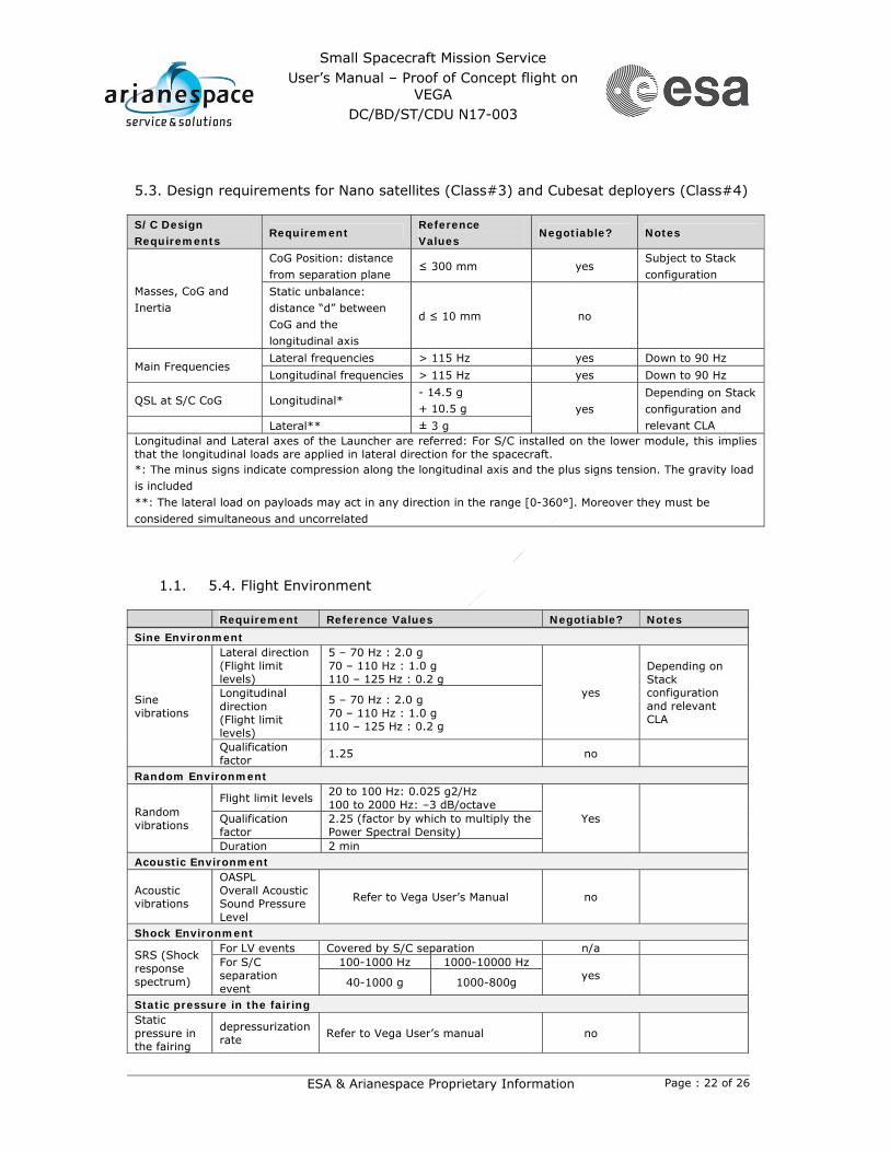
5.3. Design requirements for Nano satellites (Class#3) and Cubesat deployers (Class#4) S/C Design Requirements
Requirement Reference Values
Negotiable? Notes
Masses, CoG and Inertia
CoG Position: distance from separation plane
≤ 300 mm yes Subject to Stack configuration
Static unbalance: distance “d” between CoG and the longitudinal axis
d ≤ 10 mm no
Main Frequencies Lateral frequencies > 115 Hz yes Down to 90 Hz Longitudinal frequencies > 115 Hz yes Down to 90 Hz
QSL at S/C CoG Longitudinal* - 14.5 g + 10.5 g yes
Depending on Stack configuration and relevant CLA Lateral** ± 3 g
Longitudinal and Lateral axes of the Launcher are referred: For S/C installed on the lower module, this implies that the longitudinal loads are applied in lateral direction for the spacecraft. *: The minus signs indicate compression along the longitudinal axis and the plus signs tension. The gravity load is included **: The lateral load on payloads may act in any direction in the range [0-360°]. Moreover they must be considered simultaneous and uncorrelated
1.1. 5.4. Flight Environment Requirement Reference Values Negotiable? Notes Sine Environment
Sine vibrations
Lateral direction (Flight limit levels)
5 – 70 Hz : 2.0 g 70 – 110 Hz : 1.0 g 110 – 125 Hz : 0.2 g
yes
Depending on Stack configuration and relevant CLA
Longitudinal direction (Flight limit levels)
5 – 70 Hz : 2.0 g 70 – 110 Hz : 1.0 g 110 – 125 Hz : 0.2 g
Qualification factor 1.25 no
Random Environment
Random vibrations
Flight limit levels 20 to 100 Hz: 0.025 g2/Hz 100 to 2000 Hz: –3 dB/octave
Yes Qualification factor
2.25 (factor by which to multiply the Power Spectral Density)
Duration 2 min Acoustic Environment
Acoustic vibrations
OASPL Overall Acoustic Sound Pressure Level
Refer to Vega User’s Manual no
Shock Environment
SRS (Shock response spectrum)
For LV events Covered by S/C separation n/a For S/C separation event
100-1000 Hz 1000-10000 Hz yes 40-1000 g 1000-800g
Static pressure in the fairing Static pressure in the fairing
depressurization rate Refer to Vega User’s manual no

Small Spacecraft Mission Service User’s Manual – Proof of Concept flight on
VEGA DC/BD/ST/CDU N17-003
ESA & Arianespace Proprietary Information Page : 23 of 26
Thermal Environment Fluxes before and after Fairing jettisoning
Aerothermal and Radiative fluxes
Refer to Vega User’s manual yes
EMC Environment Spurious radiation interference levels from LV
Refer to Vega User’s manual no
Cleanliness Cleanliness Refer to Vega User’s manual no 5.5. S/C qualification Qualification to random: The spacecraft structure shall demonstrate compliance with the random vibration environment in the 20Hz - 2000Hz frequency range (refer to the levels in the above table section 5.4). Qualification to shock: When using the SSMS dispenser, the sizing shock event is the S/C separation event. The spacecraft shall demonstrate to be able to stand this separation shock.

Small Spacecraft Mission Service User’s Manual – Proof of Concept flight on
VEGA DC/BD/ST/CDU N17-003
ESA & Arianespace Proprietary Information Page : 24 of 26
6. Stack integration & Launch campaign This chapter describes the logic for the integration of the Stack and the activities during Launch campaign. The stack integration will be done in a dedicated integration facility in Europe, with the exception of the Mini Satellite (Class#1) for which the usual processing flow will apply (refer to Vega User’s Manual Section 6). The overall logistic scheme is shown below:
Spacecraft Class#2,3,4
Manufacturer
Lightband
PSC
SSMS dispenser
SAB SSMS Stack Integration
Facility
Europe
Spacecraft Class#2,3,4
Manufacturer Spacecraft Class#2,3,4
Manufacturer
Spacecraft Class#1
Manufacturer
HPF / Encapsulation
Facility
CSG
Launch Pad
CSG
Spacecraft in its container Spacecraft in its container
Stack in its container
Vega Upper Composite

Small Spacecraft Mission Service User’s Manual – Proof of Concept flight on
VEGA DC/BD/ST/CDU N17-003
ESA & Arianespace Proprietary Information Page : 25 of 26
6.1. Stack integration flow Requirement Reference Negotiable? Notes
Micro, Nano Satellites & Cubesats integration
Micro, Nano Satellites & Cubesats mating on SSMS dispenser
In Europe, in SSMS Stack Integration facility
yes
Integration in CSG facilities available as an option to be ordered by customer
Mini Satellite integration
Mini Satellites & Cubesats dispensers mating on SSMS dispenser
At CSG (refer to Vega User’s manual Section 6)
yes
6.2. S/C checks / accessibility after Stack integration Requirement Reference Negotiable? Notes
S/C Accessibility in Europe
Operations to be performed on the S/C
Not Allowed yes To be evaluated on case by case basis.
S/C Electrical checks in Europe
By means of S/C skin connection
Not Allowed yes
To be evaluated on case by case basis. If any, the S/C skin connection shall be located on the S/C face facing the fairing.
By means of S/C-LV connectors
Allowed n/a
The number of available lines through the connectors is reported in Section 4.
S/C Accessibility at CSG
Operations to be performed on the S/C
Not Allowed yes
For any “Remove before flight” items or S/C skin connections.
S/C Electrical checks at CSG
By means of S/C skin connection
Not Allowed yes
In case of anomaly only. If any, the S/C skin connection shall be located on the S/C face facing the fairing.
By means of Dispenser/LV umbilical links
Allowed n/a
The number of available lines through the connectors is reported in Section 4.

Small Spacecraft Mission Service User’s Manual – Proof of Concept flight on
VEGA DC/BD/ST/CDU N17-003
ESA & Arianespace Proprietary Information Page : 26 of 26
6.3. S/C hazardous propellant loading after Stack integration Requirement Reference Negotiable? Notes
Mini Satellite (Class#1)
S/C hazardous propellant loading
Allowed At CSG, in HPF, before mating on SSMS dispenser
n/a
Micro Satellite (Class#2)
S/C hazardous propellant loading
Allowed At CSG, in HPF, after Stack integration
yes
Nano Satellite (Class#3)
S/C hazardous propellant loading
Not allowed
Cubesats deployer (Class#4)
- - n/a
ESA UNCLASSIFIED - For Official Use
Issue Date 13 February 2017 Ref VG-AO-0-C-30001-ESA
ANNEX 2
QUESTIONNAIRE

VEGA PROGRAMRange Uncertainties
Light Satellite NameCountry of Operator/OwnerOperator/OwnerUsers and Mission Scope e.g.: EO, SCI
Mission description for info
Planning and Current Project phase schedule to Acceptance review (Gantt Chart if available)
Planned Launch dateLaunch window year launch period, day time
Flight Lifetime years, months
Attitude control concept 3-axes, spinMission specific constraints e.g.: solar aspect angleS/C sketch in stowed state including reference frame
Class of Orbit LEO/MEO/GEOType of Orbit SSO/circular/polarfor SSO, Local Time of Ascending Node [degree]Longitude of ascending node [degree]Perigee [km]Apogee [km]Inclination [degree]Argument of Perigee [degree]Eccentricity
Launch Mass [Kg]Dry Mass [Kg]
Dimensions excluding protrusions
Protrusions positions and dimensions
C.o.G. position w.r.t. the S/C separation plane (nominal and dispersed values)wrt a ref. system centered at intersection between SC long axis and separation plane
MoI w.r.t. S/C reference coordinate system where the S/C CoG is the origin (Nominal and dispersed values)S/C Interface ring sketch, dimensions, characteristics
Longitudinal modes frequencies (all modes up to 125 Hz) and relevant participating mass (in % w.r.t. the launch mass)
FEM model if available (NASTRAN files)
Lateral modes frequencies (all modes up to 125 Hz) and relevant participating mass (in % w.r.t. the launch mass)
Preferred Separation system concept pyro/non-pyroPreferred Separation Directions wrt S/C ref. frame Lateral/LongitudinalPreferred Separation orientation constraints wrt to inertial ref. frameSeparation constraints e.g.: solar aspect angle
Needed visibility, duration for commissioning [s]Max. angular rate and delta velocity range
Total Power [W]
by S/C equipment during SB on ground and launch vehicle flight phases
Critical elements acceptance temperature limits [C] Min and Max
# of electrical links S/C - EGSE
# of electrical links S/C - Launcher
RF interface requirements
Level of cleanliness and contamination
cleanliness and related contamination constraints
Accessibility requirements/constraintsPropellant [Y/N]
Propellant identification to indicate the type of propellant useddensity of liquid [Kg/m^3]volume of tank [l]fill factorliquid volume [l]liquid mass [Kg]CoG of propellant loaded tank w.r.s. to S/C coordinate systemPressurant identification to indicate the type of pressurant used
MEOP
In flight Electromagnetic Environment to indicate the RF emission in flight
On ground Electromagnetic Environment to indicate the RF emission on ground
Ground station network requirements list of needed GS in relation to separation and acquisition phases
Launch campaign requirements specific needs during campaign, e.g.: logistics, comms, clean room provisions
CAD model if available (STEP file)
to provide the number of pins for each needed connector (Lines configuration
if available - Excel file)
Misc.
EMC
Mission Description
Thermal
characteristics
Electrical interfaces
AIVO
rbital parameters
PropulsionSeparation
Physical characteristicsM
ech. Prop.