annexure- a scope of work for main boiler of work main... · annexure- a scope of work for main...
TRANSCRIPT

ANNEXURE- A SCOPE OF WORK FOR MAIN BOILER
WORK OF ERECTION, TESTING, COMMISSIONING, PERFORMANCE GUARANTEE TEST AND POST COMMISSIONING TRIAL RUN & HANDING OVER OF MAIN BOILER (STRUCTURES, PRESSURE PARTS, BOILER MOUNTINGS, SOOT BLOWING SYSTEM, FUEL SYSTEM, LINING & INSULATION, CRITICAL PIPING, HANDLING SYSTEM ETC.) FOR RENOVATION, MODERNIZATION & UPRATING (R, M & U) OF 110 MW UNIT NO. 7 TO 120 MW AT HARDUAGANJ TPS
1.0.0 BROAD SCOPE OF WORK: The broad scope of work of Main Boiler work includes, but is not limited to; following only and any other associated works and any other associated equipments & systems not specifically included in or excluded from the scope of work but essentially required for successful completion of work and guaranteed performance of the equipments & systems shall form integral part of the scope of work. Dismantling of existing equipments and systems shall be done by BHEL by engaging separate agency. However dismantling of any equipment, if required to be done as per site requirement for successful erection of new equipments and systems shall be in the scope of E&C sub-contractor
1.0.1 Tentative List of Equipments & Systems to be erected by sub-contractor in Main Boiler work is as per enclosed Annexure — Al.
1.0.2 Tentative weight of materials envisaged for erection is 3291 (THREE THOUSAND TWO HUNDRED NINTY ONE Approxi.) MT as per enclosed Annexure — A2.
1.0.3 Tentative Nos. of HP Joints envisaged are 10413 of Dia. 14 mm to Dia. 80 mm, 546 Nos. of Dia. >80 mm to Dia. 275 mm, and 30 Nos. of Dia. >275 mm to Dia. 410 mm. As per Annexure - A5
1.0.4 Dismantling of Ceiling girders, flooring and other associated structures is to be carried out after erection of temporary structure.
1.0.5 The existing columns & associated structures are to be extended /strengthened and the Boiler Drum shall be lifted and relocated at new elevation.
1.0.6 For the work of ceiling girders, Column height increase and drum lifting and other associated work one crane of capacity 250 to 300 tons shall be required tentatively for a period of 3 months. This crane shall be arranged and provided by subcontractor at his own cost. All the cranes, consumables and T&Ps shall be arranged by sub-contractor as per Annexure- A3 and terms & conditions as per Annexure-B.
The Sub-contractor has to obtain Approval, Permission & Clearances from CIB (Uttar Pradesh) as per IBR for: a) Undertaking Renovation, Modernization & Up rating of Boiler, b) Lay Out Drawings and Other Drawings of Pressure Parts, c) Erection of pressure parts, d) Stage Inspection of Pressure Parts, e) Statutory Inspection of Hydraulic Test, f) Approval of Boiler Operation after R&M works and g) Other necessary permissions & approvals required as per IBR.
The Sub-contractor has to obtain other statutory clearances and permissions from concerned authorities as required for the work and they must observe and strictly adhere to all labor & industrial laws, and other statutory laws, acts & regulations as applicable for the contract.
The Sub-contractor has to provide all required skilled & semi-skilled labors & technicians, experienced engineers & supervisors, qualified crane operators, qualified personnel for DPT, MPI, UT, Radiography, Heat Treatment, D-Metering and other tests and other Manpower. Tentative requirement shall be as per Annexure- A3.
The Sub-contractor has also to provide Ex OEM Personnel for supervision of work during erection, assembly, testing & commissioning of: Boiler Pressure Parts,
1
1.0.7
1.0.8
1.0.9
1.1.0

1.1.2
1.1.3
1.1.8
1.1.9
1.2.0
Structural, Critical Piping, Boiler Valves, Coal Piping, Burners. Boiler Drum, Soot Blowers, Hangers & Supports, Radiography Evaluation, Commissioning and any other area as required. Tentative Requirement shall be as per Annexure- A3. If Ex OEM Personnel not provided by sub-contractor then BHEL will arrange the same at risk and cost of sub-contractor. The cost incurred by BHEL shall be deducted from sub-contrctor's RA bills including BHEL overheads. The Sub-contractor has to provide all required Tools & Plants (T&Ps) in sufficient quantities including Trucks, Tractors, Trailers, Mobile Cranes, Hydra cranes , Derrick Structures, Multi Sheave Pulley Blocks, Chain Pulley Blocks, Pulls & Lifts, Manual Winches, Slings, Eye Bolts, D-Shackles, Turn Buckles, Hoists, Hydraulic Jacks, Manual Jacks, Torque Wrenches (up to 750 KG — M), Alignment Clamps, Pipe Clamps, Welding Machines. Gas Cutting Sets, TIG & Arc Welding Sets, Spanners (up to 90 mm), Files, Grinders, Drill Machines, Taps & Dies, Tube Bending Machine, Sheet Cutting/Bending Machine, Heat Treatment Equipments, Water Washing Hose Pipes and Attachments and all other types of Tools & Plants. Tentative Requirement shall be as per Annexure- A3 and terms & conditions as per Annexure-B. The Sub-contractor has to provide all required Measuring & Monitoring Devices (MMDs) in sufficient quantity including Master Level (0.02 mm/m), Spirit Level, Straight Edge, Water Level, Dumpy Level, Radiography Equipments, MPI Kit, UT Kit, Piano Wire, Plumb Line, Measuring Tape, Micro Meters (up to 500 mm), Scale, Vernier Calipers, D-Meters, Colum Alignment Checking Instruments, Dial Gauge, Tri Square and all other types of Measuring & Monitoring Devices (MMDs). Tentative Requirement shall be as per Annexure-A3. The Sub-contractor has to provide all required Consumables including Welding Electrodes & Filler Wires (BHEL approved only), D.A., Oxygen, Argon, Nitrogen and other Industrial Gases, DPT & MPI Consumables, Blue Paste, Diesel, Petrol, Kerosene and other oil, Rust Remover Compound, Sealing & Jointing Compounds, Cloths, Emery Paper, Coir Rope, Paint and all other types of Consumables as per site requirement as per Annexure - A3. The Sub-contractor has to provide all other materials and resources including sleepers, planks, scaffolding materials, tarpaulin, plastic sheets, wire brushes and all other types of other materials & resources. Proper Arrangement of House Keeping, strict compliance of Health Safety & Environment norms of BHEL, Day to Day cleaning of the entire working area and final area cleaning on completion of work including arrangement of water washing equipments and accessories is included in the Scope of Work of the Sub-contractor. All necessary arrangements are to be made by the sub-contractor for transportation of materials including providing of all required Manpower and Cranes, Hydras, Trucks, Trailers, Tractors and other means of transportation. All Necessary arrangements are to be made for handling, lifting, shifting, erection, placement, assembly, matching, alignment, supporting, welding, cutting, grinding, drilling, DPT, UT, MPI, Radiography, Heat Treatment and other associated works etc. for the materials to be erected/dismantled. Including providing of all required Manpower, T&Ps, MMDs, Consumables and Other Materials. The sub-contractor shall carry out Dismantling, Removal, Shifting of any obstructing structures, pipe lines, cables & cable trays, trench pipes, trenches, equipments, facilities etc. as required including restoration of the same on completion of work. Any re routing of pipelines, cables and cable trays, trench pipes, trenches, equipments facilities etc, if required, shall be carried out by subcontractor free of cost.
All Necessary Preparation, Development. Barricading and Marking of the Area has to be made by the sub-contractor for Storage. Fabrication, and Pre Assembly & Erection of the Materials.
The sub-contractor has to carry out Erection of Scaffolding, Platforms, Approaches as required including supply of all scaffolding materials and Dismantling of the same on completion of work.
2

Identification & Receipt of Materials at Stores & their transportation from stores to site including Necessary shifting/removal of other materials stacked on the identified material, un packing of the materials, removal of any obstructions & hindrances etc.
Transportation of dismantled components, scraps & debris generated and other materials removed to disposal yard/stores on day to day basis. After completion of work, cleaning & shifting of all type of scrap from site to scrap yard and Transportation balance/surplus materials to store. Erection of Temporary Structures supplied and transferring the load of drum on the temporary structures erected. Locking of structures/equipments and Dismantling of ceiling girders, structures, flooring and other associated equipments & assemblies. Extension, Strengthening, Modification, Rectification of existing Columns, Platforms & Other Structures and Erection of ceiling girders, structures, platforms, flooring and other structures. Lifting, Placement, Alignment & Supporting of Drum at new elevation including all necessary arrangements for Drum Lifting. Dismantling of Temporary Structures erected without damaging it and its transportation to stores for use in next unit. Erection of columns, structures, casings, supports etc. and necessary repair, rectification, refractory and other associated works. Erection, Assembly, Alignment, Matching, Welding, Cutting, Grinding, Drilling, Connection, Testing and other associated works of Materials supplied for various equipments & systems of Main Boiler work by various Units including any minor rectification, modification, adjustment, fabrication, matching, machining etc. of the supplied materials (without any extra cost to BHEL).The list of equipments and systems as per Annexure A-1 is not exhaustive and comprehensive. Any other associated works or any other associated equipments & systems not specifically elaborated in the scope of work but essentially required for successful completion of work and commissioning & operation of the equipments as per site requirement is included in the Scope of work of the Sub-contractor Marking, Dressing, Surface Preparation & Matching and other associated works of foundation and other necessary assistance to civil age_ncy for foundation. DPT, MPI, UT, Radiography & Heat Treatment of HP Joints, Critical welds and other components as per BHEL norms. Radiography of the new HP Joints as per IBR including necessary, rectification of the defects observed during radiography, Hydraulic Test and Commissioning. Any Modification, Dismantling, Assembly, Servicing and associated works in existing equipments, structures, assemblies, piping, supports, etc. as required for retrofitting of new materials. Lying of Insulation, Refractory & Cladding as per BHEL norms including curing of the refractory. Painting and Marking/Labeling of the structures, piping, equipments & other components as per BHEL norms including supply of paints The codes and standards applicable, preparation of surfaces, primer paint, finish paint, shall be as per enclosed Annexure — A4. Any other associated work and work of any other associated equipments & systems as per site requirement for successful completion of erection & retrofitting activities in all respects. Arrangement of Portable Pump of 450 kg/cm2 and other necessary equipments & accessories including laying of temporary piping and other associated works for Hydraulic Test of Boiler shall be done by sub-contractor. Hydraulic Test of Boiler and rectification of defects observed including replacement/re erection/rectification of components as required. Air/Gas Tightness Test of Boiler including installation of testing equipments, tapping points etc. and rectification of defects observed including replacement/re erection/rectification of components as required.
1.2.1
1.2.2
1.2.3
1.2.4
1.2.5
1.2.6
1.2.7
1.2.8
1.2.9
1.3.0
1.3.1
1.3.2
1.3.3
1.3.4
1.3.5
1.3.6
1.3.7
1.3.8
1.3.9
3

O
1
1.4.2
1.4.
1.4.3
1.4.4
1.4.5
1.4.6
1.4.7
1.4.8
1.4.8.1
1.4.8.2
1.4.8.3
1.4.8.4
1.4.8.5
Testing and commissioning of all equipments & systems including installation of testing equipments, tapping points etc_ and rectification of defects observed including replacement/re erection/rectification of components as required. Trial operations of all equipments & systems and rectification of defects observed including replacement/re erection/rectification of components as required. Chemical Cleaning of Boiler shall be arranged by BHEL through another agency. However, necessary assistance to the agency and co ordination with the agency shall be in the scope of the sub-contractor. Necessary assistance for other Tests of Equipments & Systems, Boiler Light Up and other pre commissioning & commissioning activities and rectification of defects observed including replacement/re erection/rectification of components as required. Necessary assistance for Performance Guarantee Test including installation of testing equipments, tapping points etc. and necessary adjustments/rectification as required. Necessary assistance for Post commissioning Trial operations of 14 (Fourteen) days, on full load and rectification of defects observed including replacement/re erection/rectification of components as required Handing Over of the Unit to the customer after successful completion of period of Post Commissioning Trial Operations. All works are to be carried out as per drawings and as per instruction of BHEL Engineer and all necessary adjustments, setting, alignment, testing and other associated works shall be carried out as per drawings and as per instruction of BHEL Engineer.
EXTRA WORKS
All rectifications/ modifications, revamping, and reworks required for any reasons not due to the fault of the contractor, or needed due to any change in deviation from drawings and design of equipments, operation/ maintenance requirements, mismatching, or due to damages in transit, storage and erection/ commissioning, and other allied works which are not very specifically indicated in the drawings, but are found essential for satisfactory completion of the work, will be considered as extra works. Extra works arising on account of the contractor's fault, irrespective of time consumed in rectification of the damage/loss, will have to be carried out by the contractor free of cost. Under such circumstances, any material and consumable required for this purpose will also have to be arranged by the contractor at his cost.
All the extra work should be carried out by a separately identifiable gang, without affecting routine activities. Daily log sheets in the pro-forma prescribed by BHEL should be maintained and shall be signed by the contractor's representative and BHEL engineer. No claim for extra work will be considered/ entertained in the absence of the said supporting documents i.e. daily log sheets. Signing of log sheets by BHEL engineer does not necessarily mean the acceptance of such works as extra works. BHEL retains the right to award or not to award any of the major repair/ rework /modification/rectification/fabrication works to the contractor, at their discretion without assigning any reason for the same. The decision of BHEL site engineer w.r.t. extra work shall be final and binding upon the sub-contractor. After eligibility of extra works is established and finally accepted by BHEL engineer/designer, payment will be released on competent authority's approval at the following rate:
MAN-HOUR RATE FOR ELIGIBLE EXTRA WORKS: Single composite average labour man-hour rate, including overtime if any, supervision, use of tools and tackles and other site expenses and incidentals, consumables for carrying out any major rework/ repairs/ rectification/ modification/ fabrication as certified by site as may arise during the course of erection, testing, commissioning or extra works arising out of transit, storage and erection damages, payment, if found due will be at Rs. 60/- per man hour.

1.4.0 1 All temp, pressure, flow sensing devices and tapping points(Up to root valve) for air i /steam /oil /water required for the boiler shall be covered under the scope of work.
1.4.1
I The erection of platforms wherever required for approaching to the different types of instruments, pneumatic actuator and electrical actuator etc shall be covered under the scope of work.
2.0.0 SPECIAL TERMS & CONDITIONS :-
2.0.1 Liquidated Damages for Delay: _ Completion Period shall be 150 Days from the date of commencement of work to Commissioning of the Unit. Penalty/ LD for Delay attributable to sub-contractor shall be as per 0.5% of the contract value per week or pan thereof subject to maximum of 10% of the contract value.
2.0.2 OVERRUN COMPENSATION 2.0.2.1 Over Run Compensation (ORC) is payable by way of rate revisions for periods beyond
original contract period due to reasons not attributable to sub-contractor, subject to the following terms and conditions:
2.0.2.2 Rates shall be increased by 10% for the first twelve months of one or more extensions beyond original contract period. For the next twelve months of further extensions if any, rates shall be increased as above by 10% over the previous twelve months, and similarly for each subsequent twelve months extension.
2 .0.2.3 The amount of increase payable per month due to rate revisions is subject to a minimum of Rs.1,00,000/- per month and a maximum of Rs 10 , 00,000/- per month.
2.0.2.4
2.0.2.5
Should there be any Time extension' for reasons attributable only to the contractor, then the work shall be executed by the contractor at the rates applicable for the period the work was planned. Payment of ORC shall be regulated as follows: i) Contractor is entitled to Over Run Compensation (ORC) only for the portion of backlog attributable to BHEL.
2.0.2.
2.0.3
ii) 50% of the compensation as per clause 2.0.2.3 is allocated for deployments of resources agreed as per the joint programme drawn vide 2.0.2.4. Payment shall however be based on the actual deployment of resources for the month as certified by BHEL, as per weightages assigned therein
iii) 50% of the compensation as per clause 2.0.2.3 is allocated for achieving of planned progress agreed as per the joint programme drawn vide 2.0.2.4. Payment shall be on pro rata basis for actual achieved quantities
iv) Total Over Run Compensation shall be limited to 10% of the executed contract value as certified in Final Bill. For this purpose executed contract value excludes PVC, ORC. Supplementary/Additional Items and Extra Works done on Manday rate basis.
Contractor shall not be entitled for any Over Run Compensation (ORC) for the portion of backlog attributable to the contractor. Such works shall be executed at the rates applicable for the period the work was_planned. Electrical power connection at one point and supply for execution of job shall be free. However, supply used for stores and office shall be on chargeable basis. For this the sub-contractor shall apply to UPRVUNL for electrical connection to concerned distribution agency of UPRVUNL after completing all formalities. Bills for electricity consumed for office and stores will be settled by the sub-contractor. All necessary arrangements i.e. extension switch boards with MCBs of required capacity for tapping power shall be arranged by sub-contractor.
5

2.0.3
2.0.4
2.0.5
2.0.6
2.0.7
2.0.8
2.1
a)
b)
e)
f)
g)
Electrical power connection at one point and supply for execution of job shall be free. However, supply used for stores and office shall be on chargeable basis. For this the sub-contractor shall apply to UPRVUNL for electrical connection to concerned distribution agency of UPRVUNL after completing all formalities. Bills for electricity consumed for office and stores will be settled by the sub-contractor. All necessary arrangements i.e. extension switch boards with MCBs of required capacity for tapping power shall be arranged by sub-contractor. Space for Office, Dark Room and Stores shall be provided to the sub-contractor and the Sub-contractor has to build and furnish office, dark room & stores at their own cost. The sub-contractor shall arrange for sufficient nos. of flood lights and other arrangement for ensuring round the clock work. Necessary co ordination with stores and other agencies shall be in the scope of the sub-contractor. The sub-contractor shall submit daily progress report and attend review meeting with BHEL on day to day basis. The warranty for the equipment shall be for a period of 12 (Twelve) Months from Handing Over of the Unit or Performance Guarantee Test which ever is later and all defects observed during this period shall be attended by the Sub-contractor free of cost. The sub-contractor shall arrange accommodation, transport, medical, sanitary, safety and other arrangements for all Manpower at their own cost. The sub-contractor must maintain proper system of documentation for Quality, Safety, HSE and other aspects so as to fulfill the requirement of ISO. OHSAS, 5S, SA 8000 and other National/International Standards TERMS OF PAYMENT:
85 (Eighty Five) °A of the contract value along with corresponding service tax as Monthly Progressive Payments on pro rata basis (Rate per MT) for actual completed work. 1 5 (Fifteen) % of the contract value along with corresponding service tax as Mile Stone Payments on pro rata basis (Rate per MT) for actual completed work , namely,
i. 10 (Ten) % on completion of Mile Stones ii) 2 96 on PG test and iii) 3 % on handing over the unit to customer.
Above payments shall be released after adjustment of CV based on the actual work carried out.
Rate per MT shall be further subdivided as follows for purpose of measurement - a. Monthly Progressive Payments on pro rata basis:
i. 5% for transportation of materials to site for erection, ii. 35% for erection of materials in position, iii. 45% for matching, alignment, welding, supporting, connection, final assembly
of materials erected. b. Mile Stone Payments on pro rata basis
i. 2% On completion of Hydraulic Test of Boiler ii. 1% On completion of Boiler Light-Up iii. 1% On completion of Safety Valve Floating iv. 1% On Providing facilities (Clause no. 2.4) to BHEL v. 5% for providing Ex-BHEL personnel as per Annexure-A3 vi. 2% for completion of PG test. vii. 3% for Handing Over of Unit.
Security Deposit shall be released only on completion of warranty period of 12 Months and fulfillment of all contractual obligations. All payments shall be subject to statutory deduction as per rule.
Necessary documents as specified in GSCC shall be submitted with bill.
All payment shall be made by Electronic Fund Transfer and necessary Bank Details shall be furnished by the sub-contractor.
6

TAXES, DUTIES AND OCTROI CHARGES TDS under Income Tax, Sales Tax, Vat etc, if any, shall be deducted at prevailing rates on gross invoice value from the running bills unless Exemption Certificate from appropriate Authority / Authorities is furnished. Price quoted shall be inclusive of all taxes, duties except service tax. The service tax, as legally livable & payable by the sub-contractor under the provisions of applicable law/act, shall be paid by BHEL as per sub-contractor's bill. However, sub-contractor shall have to submit proof of service tax deposited by them immediately after the deposit but not later than the next bill submitted after the due date of deposit. The sub-contractor shall furnish proof of Service Tax registration with Central Excise Division covering the services covered under this contract. Registration should also bear endorsement for the premises from where the billing shall be done by sub-contractor on BHEL for this project. Sub-contractor shall get his organization registered with concerned sales tax/VAT authorities within 15 days of award of this contract, if applicable. The delay on this account and delay in bringing the material shall be to sub-contractor's account and no extension of time shall be allowed on this account. The sales tax/VAT registration for this sub-contractor shall be forwarded to BHEL within 30 days from the date of LOI. In case the sub-contractor is already registered for sales tax/VAT with Govt. Authorities he must quote his registration no, while submitting their tender. Sub-contractor has to make his own arrangement at his cost for completing the formalities, if required, with Sales Tax Authorities, for bringing his materials, plants and equipment at site for the execution of the work under this contract. No road permit shall be issued by BHEL for sub-contractor's materials/equipments. OCTROI, if any, payable on BHEL's consignments will have to be initially paid by the sub-contractor and necessary reimbursement claimed from BHEL duly supported by documentary proof. Whenever the amount payable in one particular case is more than Rs. 5000/-, the sub-contractor may request BHEL well in time to issue cheque / draft in favor of authorities. Other Terms & conditions shall be as per GSCC. In case of any conflict between the special terms and conditions specified in the scope of work and GSCC attached, the conditions of scope of work shall prevail. Facilities to be provided by Sub -contractor to BHEL The Sub-contractor shall provide 1 Laptop and 1 Desk Top Computer of latest configuration along with 3-in-1 printer (PSC printer), UPS. Data card for accessing internet (Modem), other peripherals, accessories, Stationary & cartridges and one mobile phone with rental & call charges Exclusively for BHEL use from start till completion of work. The Sub-contractor shall also provide one qualified computer operator, one office assistant and 1 attendant for BHEL Site Office/colony on round the clock basis. All charges shall be born by Sub-contractor.
2.2 2.2.1
2.2.2
2.2.3
2.2.4
2.2.5
2.3
2.4
7

1.0
ANNEXURE — Al
TENTATIVE LIST OF EQUIPMENTS & SYSTEMS COVERED IN MAIN BOILER
Equipments & Systems covered in Main Boiler includes erection/retrofitting and other associated works of, but not limited to, following:
STRUCTURES
The existing boiler column structure will be retained. For the system requirement, the height of existing ceiling will be increased. New ceilings girders to be erected & aligned to suit new pressure parts arrangement.
New necessary hand rails and floor grills for the system requirement to be erected.
Temporary structures shall be erected for transferring the load of existing drum to the structure during dismantling and re-erection.
Assistance during condition assessment study of existing structure and strengthening the structure as per requirement.
New Ceiling girder beams
Structural required for increasing the column height.
Boiler roof structure
Hand rails and floor grills
Boiler roof sheeting
Main Floors modification to connect the new Furnace configuration
Platform extension Structures
Boiler Ceiling & Roof Structures with Roof sheeting
Temporary Structure for Drum support
Extension of existing columns
ID Fan, PA Fan, and FD Fan handling Structures
PRESSURE PARTS
Complete pressure parts arrangement will be new with latest design practices and all the pressure parts, economizer, furnace water walls. LTSH and platen super heaters, re heater. SH/RH de-super heaters, steam cooled wall tubes, headers, inter connecting piping, etc. will be covered for the proposed membrane design boiler.
DRUM, DRUM INTERNALS & DOWN COMERS
Assistance for life assessment study of drum & down comer.
Modification of existing down comer arrangement & connection to bottom ring header.
Erection of temporary structure for supporting the drum and lifting, placement, alignment, supporting, connection of drum at the new elevation.
Phosphate dosing piping inside drum and feed inlet line inside drum.
Drum manhole gaskets and fasteners.
New suspension rods for drum.
New down comer piping.
8
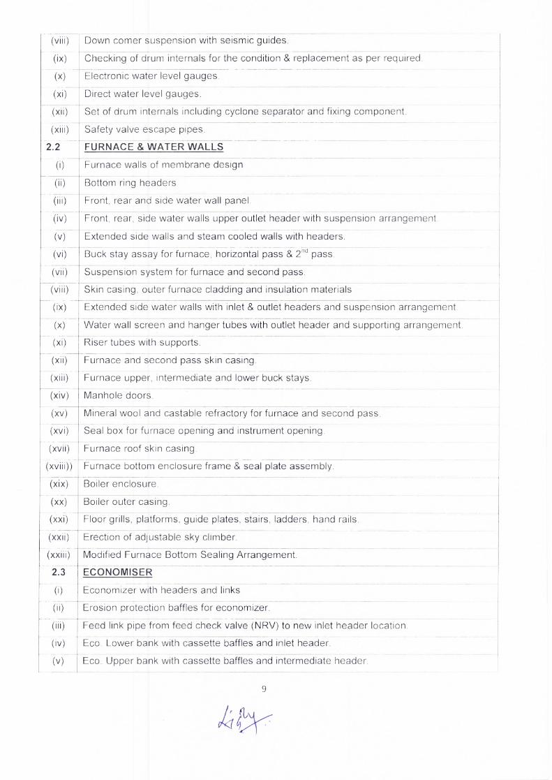
(viii) Down corner suspension with seismic guides.
(ix) Checking of drum internals for the condition & replacement as per required.
(x) Electronic water level gauges.
(xi) Direct water level gauges.
(xii) Set of drum internals including cyclone separator and fixing component.
(xiii) Safety valve escape pipes.
2.2 FURNACE & WATER WALLS
(i) Furnace walls of membrane design
(ii) Bottom ring headers
(iii) Front, rear and side water wall panel.
(iv) Front, rear, side water walls upper outlet header with suspension arrangemen t
(v) Extended side walls and steam cooled walls with headers.
(vi) Buck stay assay for furnace, horizontal pass & 2 nd pass.
(vii) Suspension system for furnace and second pass.
(viii) Skin casing, outer furnace cladding and insulation materials
(ix) Extended side water walls with inlet & outlet headers and suspension arrangement.
(x) Water wall screen and hanger tubes with outlet header and supporting arrangement.
(xi) Riser tubes with supports.
(xii) Furnace and second pass skin casing.
(xiii) Furnace upper, intermediate and lower buck stays.
(xiv) Manhole doors.
(xv) Mineral wool and castable refractory for furnace and second pass.
(xvi) Seal box for furnace opening and instrument opening.
(xvii) Furnace roof skin casing.
(xviii)) Furnace bottom enclosure frame & seal plate assembly.
(xix) Boiler enclosure.
(xx) Boiler outer casing.
(xxi) Floor grills, platforms, guide plates, stairs, ladders, hand rails.
(xxii) Erection of adjustable sky climber.
(xxiii) Modified Furnace Bottom Sealing Arrangemen t
2.3 ECONOMISER
(i) Economizer with headers and links
(ii) Erosion protection baffles for economizer.
(iii) Feed link pipe from feed check valve (NRV) to new inlet header location.
(iv) Eco. Lower bank with cassette baffles and inlet header.
(v) Eco. Upper bank with cassette baffles and intermediate header.
9

2.5
(i)
(vi) Eco. Hanger tubes with outlet header.
(vii) Eco. Outlet links to drum with supports.
viii) Expansion bellows.
(ix) Hand rails and floor grills of economizer floor.
(x) Eco. Hopper with manholes.
2.4 SUPERHEATER & SH DESH
(i) Ceiling tubes with header and links, roof seal bands and insulation material.
(ii) Links from drum to radiant roof sh.
(iii) Radiant roof SH with inlet & outlet headers and supporting arrangement.
(iv) Links from radiant roof outlet header to side steam cooled wall SH inlet header.
(v) Second pass side steam cooled wall SH panels with inlet and outlet headers and supporting arrangement.
(vi) Second pass front steam cooled wall SH panels with inlet and outlet headers and supporting arrangement.
(vii) Extended side wall SH panels with inlet & outlet headers and supporting arrangement
(viii) Rear roof SH with outlet header.
(ix) Extended bottom SH panels with outlet header.
(x) Low temp. SH (LTSH) with terminal tubes, inlet & outlet headers, bend protection cassette baffles & supporting arrangement.
(xi) Links from LTSH outlet header to DESH.
(xii) De Super Heater (DESH).
(xiii) Links from DESH to platen inlet header.
(xiv) Platen SH with inlet & outlet headers & supporting arrangement.
(xv) Final SH with inlet & outlet headers & supporting arrangement.
REHEATER & RH DESH
Re Heater coils with inlet & outlet headers and supporting arrangements.
(ii) RH De Super Heater.
3.0 BOILER MOUNTING SYSTEM
3.1 Drum safety valve with silencers for lowest set safety valve.
SH safety valves and Electromatic relief valves (ERV) with silencers for lowest set safety valve.
3.3 RH safety valves with silencers for lowest set safety valve.
3.4 Start up vent valve with silencers.
3.5 Complete DESH station for SH with necessary Control valves, Isolation valves & bypass valves, drain valves, flow orifices with root valves, etc.
3.6 Complete DESH station for RH with necessary Control valves, Isolation valves & bypass valves, drain valves, flow orifices with root valves, etc.
3.7 SH spray flow orifice with root valves.
3.2
10

3.8 RH spray flow orifice with root valves.
3.9 SH/RH spray & drain lines pipe with fittings.
3.10 Air vent and Drain lines including valves for the trim piping inside the boiler terminal points (from feed control station to main Steam stop valve).
3.11 Feed inlet check valve.
3.12 Blow down valve for down comer
3.13 Sample coolers with support.
3.14 Soot blower pressure reducing station valve.
3.15 Forced drain system with thermal drain valves for soot blowers.
3.16 Direct water level gauges.
3.17 Main steam stop valves.
3.18 Attemperation flow nozzle.
3.19 SH spray inlet block valve (pneumatic actuator).
3.20 SH spray control valve (pneumatic operated).
3.21 SH spray line isolation valve (motor operated).
3.22 SH spray line isolation valve (hand operated).
3.23 RH inlet block valves (pneumatic operated).
3.24 RH spray control valves (pneumatic operated).
3.25 RH spray line isolation valve (motor operated).
3.26 RH spray line isolation valve (hand operated).
3.27 Drum safety valves.
3.28 Electromatic relief valves (ERV) with supports.
3.29 Silencers for electromatic relief valves.
3.30 Trim piping & fittings with supports (start up vent, spray control station etc.)
3.31 Start up vent.
3.32 Start up vent silencer & supports.
3.33 Air vents lines.
3.34 Drain lines.
3.35 Soot blower thermal drain valve.
3.36 Soot blower purging valve.
3.37 Feed Control Valves
3.38 Hanger support and tie rods for MS, HRH, and CRH and feed piping.
3.39 Complete PRDS station including control valves, isolating valves, bypass valves, headers, relief valves, drains, traps and injection valves.
4.0 SOOT BLOWERS AND SOOT BLOWING SYSTEM
4.1 Wall blower with wall box.
4.2 Furnace temperature probe.
11

4.3 Long retractable Soot Blowers.
4.4 Wall boxes for LRSBs.
4.5 Soot blower piping with valves, fittings and supporting arrangement.
6.0 FUEL FIRING SYSTEM (COAL &OIL)
6.1 The indirect firing system shall be replaced with the state of art direct firing system constituting 04 Nos bowl mills and 02 Nos PA Fans.
6.2 Tilting Tangential Burner assembly consisting of:
(i) Coal Nozzles.
(ii) Air Nozzles.
(iii) Oil Nozzles
(iv) Air cooled Oil guns
(v) Burner tilt mechanism
(vi) Secondary air dampers
(vii) HEA igniters
(viii) Visible light (BHELSCAN) safe flame scanners
6.3 Coal piping along with fuel inlet elbow, Coupling, orifices, coal pipe supports and hangers.
6.4 Fuel oil piping from Boiler front to individual corners with necessary valves & fittings.
6.5 Scanner & Gun cooling air system constituting 100% AC & DC scanner air system and accessories.
6.6 One no. LDO & One no. HFO pump along with associated strainers, heaters, piping and valves.
LDO/HFO lines from FO Pump House to Boiler
6.8 Seal Air ducting, filters and dampers.
6.9 HEA ignitors purge air system.
6.10 SADC Dampers & its actuators etc.
6.11 Tubes and pipes.
6.12 Structurals,
6.13 100°/0 scanner air fan AC & DC and accessories and fixing components.
6.14 Air cooled steam atomized oil gun assembly.
6.15 Oil burner corner fittings.
6.16 Oil burner control valves.
6.17 Scanner guide pipe assembly.
6.18 Complete fuel oil firing and control system.
6.19 Steam piping and control valves.
6.20 Main oil flow pressure and trip valves.
6.21 SADC system with remote manual operational facility.
6.22 Control valve for oil heating station.
12

6.23 Steam tracing system with control valves.
6.24 Oil system control valves and trip valves.
6.25 Purge Air system for HEA ignitors.
6.26 Scanner Air system piping.
6.27 Scanner guide pipe assembly.
6.28 Dampers in scanner air system.
6.29 Additional structures for scanner air piping.
6.30 Wind Box Assembly with supports.
6.31 Aerofoil instrumentation tapping on air ducting.
6.32 Structural.
6.33 Coal piping straight and ceramic lined bends.
6.34 Fuel inlet elbows.
6.35 Coal pipe supports and hangers.
6.36 Coupling and orifices.
6.37 Coal Piping.
6.38 Igniter Fan Assy.
7.0 LINING & INSULATION AND REFRACTORY
7.1 Complete lining and insulation for the main boiler, critical piping, APH and fans is included.
7.2 Complete thermal insulation including cladding, lagging, reinforcement, wire mesh, supports etc. will be furnished.
7.3 Fixing Components , Wool Mattresses and Plain & Ribbed Aluminum Sheeting for furnace walls, second pass walls, pent house sides, bottom extended side walls, Air Heater, Wind Box, ID fans Drum dished end, Down comers, Economizer Outlet pipe to drum, Soot blower steam piping, Boiler integral piping, valves and fittings, vents, exhaust piping, oil lines, MS/HRH/CRH/Drip Lines/Extraction Lines etc., ducts(Eco to AH, AH to ESP, ESP to ID fans, ID fans to Chimney and hot air duct to wind box and pulverisers) and other associated areas.
7.4 Castable refractory, Pourable refractory and insulating bricks for furnace, second pass, pent house roof, pent house bottom, extended side wall, TAPH and other associated areas.
8.0 CRITICAL PIPING: -
Includes the assistant in RLA study including supply of consumables.
8.1 Main Steam Line from SH outlet header upto HP turbine inlet.
8.2 Hot Reheat Line from boiler Re heater outlet header to IP turbine inlet.
8.3 Cold Reheat Line from HP turbine outlet to Boiler re-heater inlet header.
8.4 I Feed water line from feed control station to economizer inlet header
8.5 For all above system, sufficient quantities of piping bends and fitting have been included for interfacing with boiler.
8.6 Complete hangers & Supports required for MS, CRH & HRH, BFD from control station up to ECO inlet, APRDS piping from MS header up to Control station and other Piping system
13

Drains and vents required for MS, HRH and CRH piping system.
Auxiliary steel structures for the above piping system. Auxiliary steel structures (for hangers) mean those structures which are connected to main columns, auxiliary columns, main beams, secondary beams, floor and wall beams, etc.
Auxiliary PRDS including pressure reducing valves pneumatically operated, De Super Heater, Isolation Valves, Bypass Regulation, Vents, Drains and Instrument root valves
Pipes required for Aux. PRDS station along with safety valves.
Fuel oil lines, steam lines and steam tracing lines from fuel oil pumping unit to Boiler front.
Steam Piping and Valves for Mill inert system.
Service Water and cooling water piping and valves for mills.
Instrument/service air lines and valves to mills/feeders and burners.
Feed Control station including control valves, isolation valves, drains, vents, root valves etc
Insulation materials for MS/HRH/CRH and all other lines that are replaced as new by PC etc.
All drain piping to CBD and IBD vessels.
Flow Nozzles for Main Steam Line (2 Nos) and Feed VVater line(1 No).
Control valve and level indicator for CBD expander.
Aux steam piping from PRDS station to various equipments like, SCAPH. Pump house, steam tracing, oil atomizing, etc.
Main steam line stop valve near boiler — 2 nos.
All local gauges & switches (PG, TG with TVV, LG, LS, PS, Sigth flow indicators etc.)
(iv) Control valve for CBD expander. All local gauges and switches in the replaced systems.
(v) FO lines from FO pump house to boiler front.
(vi) HFO return line from boiler front to FO pump house.
(vii) LF0 from pump house to boiler front.
(viii) Aux. steam line for FO tracing (boiler to pump house).
Fuel Oil tracing lines with steam traps and valves.
9 HANDLING SYSTEM
Long length Micro processor based volumetric Coal Feeders to match the
Bunker & Mills centerline.
Complete 24"INLET 8650cd Gravimetric feeder
Complete replacement of Feeder o/I 'so' gate, Feed pipe, Down spout, coal valve,
(ix)
.0
9.1
9.2
8.3 Bunker
8.7
8.8
8.9
8.10
8.11
8.12
8.13
8.14
8.15
8.16
8.17
8.18
8.19
(iii)
that are supplied as new.
8.4
10.0
emptying chute
Structural material & Hoist for FD fan, Electrical Hoist for ID & PA fans and Furnace maintenance platform
ANY OTHER ASSOCIATED EQUIPMENTS & SYSTEM OF MAIN BOILER
I4

No.off Weight per Boiler in Kgs
12400
45600
143200
168500
106400 7100
470800
136500 189500 11000 12500 21500 52000
4
Complete replacement of Drum internals and suspensions for ID 49-60 Furnace Wall Complete replacement of VVaterwall headers (WW Lower and Upper . Front ,Rear, Side, Extd side, Rear VVVV Screen, Rear VVVV Hanger) Complete replacement of WW pannels of all the four sides including Burner Panels and Extended WVV pannels Complete replacement of WW Screen tubes, Hanger tubes, Rear Arch tubes, Lower and Upper corner transition tubes, Relief tubes and Downcomer Piping and the necessary Suspensions and Supports for the same.
Replacement of complete Buckstays in I & II Pass Seal Boxes for Furnace and Instrument opening
Sub-total
Second Pass Complete replacement of LTSH Coils & terminal tubes Complete replacement of Economiser - Coils & Supports Economiser inlet, outlet and Inter headers
Sub-total
SH / RH system Complete replacement of LTSH inlet & Outlet headers, Platen SH Inlet & outlet header, SH Side wall In/out header, SH Roof In/out Header, SH Front Inlet header and Rear outlet header. SH junction header
Complete replacement of Platen SH Coils Complete replacement of Radiant (I st pass) roof tubes
Superheater components: Supports & Suspensions [partial], Steam cooled spacer, Screen tubes.
SH / RH DeSuperheater and Links
Complete Replacement of RH inlet & Outlet header
423000
10
12
12
17 15
16 17
40500
39500 11000
79000
8000
8700
70800 11500
Complete replacement of RH Front & Rear coils Complete replacement of RH supports.
11
ANNEXURE A2
TENTATIVE WEIGHT OF MATERIALS TO BE ERECTED FOR MAIN BOILER WORK
Drum Internals
5
6
7
9
11 19 19 19 Economiser Feed Pipe & Link Pipes 19 Economiser Hanger tubes and Header supports 11 Complete replacement of SH Panels (Front, Rear, Side, Roof)
PG Description
Pressure Parts
15

114800
60 nos 10300 4300
398400
Complete Re-insulation for boiler/duct to be carried out Complete replacement of Seal Plate Assy, Deck support, Furnace bottom, roof & extended side Complete replacement of Boiler Skin Casing Complete replacement of Insulation - Fixing components & sheeting Complete replacement of Mineral wool Mattress Complete replacement of Castable refractory Complete replacement of Pourable insulation
Replacement of Ceiling structures, Main floors & Platforms, boiler & Air-heater columns , Fan handling equipments, replacement of Grills/hand rails wherever required, replacement of roof Metapoly sheets
Fuel Firing System
24
20 21 28
30
31 32
33
35, 36, 39
42
43
45
47
24
42
65 67
99
Complete replacement of Spray systems of SH/RH [piping, valves & fittings] and other Trim Piping [sampling lines, drains and vents]
LRSB (20 no's) & Wall blowers (40 no's) SB piping & Fittings, SB Pr. Red Valve and Supports Replacement of Access Doors
Sub-total
Insulation & Refractory
Sub-total
Structures
Oil system: Complete replacement of system in boiler front ,corner station with piping, valves and fittings
Complete replacement of Seal Air/Scanner & Gun cooling air system with fans and pipings Complete replacement of Wind box Assembly with ignitors, scanners & oil guns Coal System: Complete replacement of Coal Pipes, bends and supports
Sub-total Valves
Complete replacement of all the Valves in boiler area (Boiler safety valves, Spray system, SB system, drains and vents) Complete replacement of all the Valves of Fuel oil system at boiler front.
Sub-total Handling System ,
Complete 24'1 NLET 8650cd Gravimetric feeder Complete replacement of Feeder oil Isol gate, Feed pipe, Down spout, coal valve, Bunker emptying chute Structural material & Hoist for FD fan, Electrical Hoist for ID & PA fans and Furnace maintenance platform
Sub-total
Grand Total
70500
8100 34000
178500 78500 70500
440100
1219000
22000
30900
37000
104700
194600
300
20811 nos 350
2570 nos
23381
4 nos 53000 49100
7200
109300
3290981
16

2.0.1 2.0.2 2.0.3 2.0.4 2.0.5 2.0.6 2.0.7 2.0.8 2.0.9 2.1.0 2.1.1
3.0.0
4.0.0
4.0.1 4.0.2 4.0.3 4.0.4
ANNEXURE A3
TENTATIVE REQUIRMENT OF MANPOWER & OTHER RESOURCES
1.0.0 GENERAL MANPOWER Nos.
1.0.1 Site In charge 1
1.0.2 Engineer 8
1.0.3 Supervisor 32
1.0.4 Store Keeper/ Time Keeper 3/2
1.0.5 HP Welder 15
1.0.6 Structural Welder/LP Welder 15
1.0.7 Gas Cutter 15
1.0.8 Grinder Man 9 Mill Wright Fitter 3 Pipe Fitter 15 Structural Fitter 10
1.1.2 Junior Fitter 15 Electrician 5 Junior Electrician 5 Sarang 9 Rigger 100 Mason 6 Sheet Fabricator 10 Lagger 50 Helper 150 Painter 20
Total 498
2.0.0 Ex OEM/ BHEL Personnel Man X Months Boiler Pressure Parts 2X5 Structural
2X3 Refractory & Insulation 1X2
Critical Piping 1X2 Boiler Valves 1X3 Burners 1X2 Hangers & Supports 1X2
Commissioning 2X1 Coal Piping 1X2 Soot Blower 1X1 Radiography Evaluation 1X3
Total 35 man months TESTING TEAM Teams
3.0.1 Radiography 3 Heat Treatment-Stress relieving 3
1
3.0.4 1 3.0.5 1
Quantity
1 1 1 2
3.0.2 3.0.3 D-Metering
MPI Ultrasonic Testing
3.0.6 2 DP Test T&Ps, MMDs, Consumables & Other Materials
Crawler /Mobile Crane (300/250T) Crawler /Mobile Crane (150/100T) Crawler /Mobile Crane (75T) Mobile Crane (20T)
17

4.0.5 4.0.6 4.0.7 4.0.8 4.0.9 4.1.0 4.1.1 4.1.2 4.1.3 4.1.4 4.1.5 4.1.6 4.1.7 4.1.8
Hydra Crane (14/12T) Tractor & Trailer 15/20T Truck — 9T Derrick Structure Electric Winch 15T/10T/5T Multi Sheave Pulley Block — 60T/100T Passenger Cum Goods Hoists Hydraulic Jacks 100T/50T/25T Chain Pulley Block — 10T/5T/3T Heat Treatment/SR Equipment MPI Kit UT Kit Welding Generator Welding Transformer
4.1 .9 4.2.0 4.2.1 4.2.2 4.2.3
Motorized Hydraulic Test Pump Torque Wrench 400 KGM/800 KG M Gas Cutting Set TIG Welding Set Arc Welding Set
4.2.4 4.2.5 4.2.6
Inside/Outside Micrometer (up to 500 mm) Micrometer 25/50/300 Magnetic Base Dial Gauge Electrode Baking Oven Portable Oven Drum Lifting Arrangement
4.2.7 4.2.8 4.2.9
4.3.0 4.3.1 4.3.2
Sleepers Scaffolding Materials Water Washing Equipments
Dumpy Level Column Alignment Checking Device Piano Wire Set of Spanners up to 90 mm Welding Electrodes & Filler Wires DA, Oxygen, Argon Gas DPT Kits Drillin g Machines D-shackles, wooden planks, Slings, Huck-chuks etc. Other T&Ps,MMDs , Consumables & Materials
Master Leve Spirit Level Water Level
— 0.02 mm /m
2 6 6
As required 2
As required As required As required As required As required As required As required
As required
2 2 3 2
2/2/4 1 2
2/2/4 4/8/12
3 1 2
20 10
1 2/2 15 15 20 2
4/4/2 As required
2 15
As required 200
1 Set 2 sets
4.3.3 4.3.4 4.3.5 4.3.6 4.3.7 4.3.8 4.3.9 4.4.0 4.4.1 4.4.2 4.4.3 4.4.4
4.4.5
Note: The above list is only tentative and does not list out each and every item or grade of manpower or the quantity thereof. The Sub-contractor has to deploy all Manpower, T&Ps, MMDs, Consumables and other materials as required to complete the entire scope of work. The deployment of cranes shall be as per site requirement.
9[1 G 18

ANNEXURE A4
SPECIFICATION OF PAINTING WORK
The following Indian Standards may be referred to for carrying out the painting job: IS - 1303, 2379, 1477 , 2524, 2395 , 2338, 6278, 3140, 158, 2074, 104, and 2932.
All surfaces to be painted shall be thoroughly cleaned of all grease, oil, loose mill scale, dust, rust and any other foreign matter by mechanical cleaning with power tool, scrapping with steel wire brushes, and sand scrapping with wire brush/emery paper as per requirement. Cleaning with solvents shall be adopted only after approval of the customer.
After the surface is prepared, one coat of Zinc Phosphate primer conforming to IS: 2074 shall be applied. After first coat is dried up completely, second coat of red oxide primer shall be applied by brushing to ensure continuous film. The dry film thickness of each coat shall be minimum 25 microns.
Synthetic enamel paint conforming to IS: 2932 shall be used for finish coats. The color/ shade shall be as approved by the customer. After cleaning the dust on the dried up primer, first coat of synthetic enamel shall be applied. After this first coat dries up hard, the surface should be wet scrubbed cutting down to smooth finish and ensuring that at no place the first coat is completely removed. After applying second coat, allowing the water to get evaporated completely, third finish coat of painting shall be applied.
For all electrical equipment, powder coating shall be done as per the relevant standard.
Painting and Marking/Labeling of the materials erected. Supply of paints is included in the Scope of Work of the Sub-contractor.
1.0
2.0
3.0
4.0
5.0
6.0
(>)")--- ; 19

ANNEXURE — A5
HP ERECTION WELDS DETAILS
PG NO DESCRIPTION MATERIAL OD(mm) T(mm) NO OF WELD
S
04to07 RISER PIPES SA106 Gr.0 127 12.5 288
04to07 HAND HOLE PIPE ASSY. SA106 Gr.0 127 20 12
04to07 DOWN COMER PIPES SA106 Gr.0 406.4 32 26
04to07 RING HEADERS SA106 Gr.0 406.4 50 4
04to07 PANEL ARRGT. SA210 Gr.0 63.5 4.8 2200 REAR ARCH, HANGER, SCREEN & EXTN 4.8 / 7.1
04to07 WALL TUBES. SA210 Gr.0 63.5 / 76.1 330
10to1 2 SH.CONN PIPE EXT.SID.IN SA106 Gr.0 108 12.5 18
10to1 2 SH.CONN PIPE EXT.SID.OUTLET SA106 Gr.0 108 12.5 8
10to1 2 SH.CON PIPE FROM DRUM SA106 Gr.0 127 12.5 36 SA106 Gr.0 / SA 234
10to1 2 SH.SIDE WALL OUT HDR WPC 273 28
SA106 Gr.0 / SA 234 10to1 2 SH.SID WALL HDR + ELBOW WPC 273 32 2 10to1 2 RG PLUG + PIPE SA182 F22 / SA 335 P22 6
10to1 2 LTSH COILS + LOW LOOSE TUBE+HDR SA210 Gr.0 44.5 4 546
10to1 2 SH.PANELS ( BACK PASS ) SA210 Gr.0 44.5 5 1084
10to 12 LTSH COILS LOWER + UPPER SA213 T11 44.5 4 312
10to1 2 STEAM COOL SPACER TUBE SA213 T11 44.5 5 26
10to1 2 LTSH COILS UPPER TERM TUBE SA213 T11 44.5 5.3 - 312
10to1 2 LTSH COILS TERM TUBES+ HEADER SA213 T11 44.5 5.9 312
10to1 2 SH.RADIANT ROOF SA213 T11 51 5 266
10to1 2 VER.PLATEN SH COIL SA213 T22 44.5 6 - 130 - 10to1 2 VER.PLATEN SH COIL SA213 T22 44.5 7.1 . 195
10to1 2 VER.PLATEN SH COIL SA213 T22 44.5 9 65
1 5to1 7 RH. FRONT +NIPPLE SA213 T11 /SA 213 T11 54 4 86
15to17 RH. FRONT +NIPPLE SA213 T11 /SA 213 T11 . 54 7.1 86
1 5to1 7 RH. FRONT +RH.REAR SA213 T11 / SA 213 T22 54 4 172
1 5to1 7 RH. FRONT +NIPPLE SA213 T22 / SA 213 T11 44.5 7.1 43
1 5to1 7 RH. FRONT +NIPPLE SA213 T22 / SA 213 T22 54 4 43
1 5to1 7 RH. FRONT +RH.REAR SA213 T22 / SA 213 T22 54 4 43
1 5to1 7 RH. FRONT +NIPPLE SA213 T22 / SA 213 T22 54 5.6 43
1 5to1 7 RH. FRONT +NIPPLE SA213 T22 / SA 213 T22 54 7.1 129
19 R.G PLUG + PIPE SA105 / SA106 Gr.0 4
20

D60.3(2")
D60.3 (2")
D33.9(1")
D33.4 (1")
D21.3 (1/2")
D21.3 (1/2")
D60.3 (2")
D48.3 (1 1/2")
D33.4 (1")
D60.3 (21_
D60.3(2")
D33.4 (1/2")
D60.3 (2")
D108.0
D108.0
D158.8
3.91 (SCH 40)
3.91 (SCH 40) 3.38 (SCH 40)
6.35 (SCH 160)
2.77 (SCH 40)
4.78 (SCH 160)
3.91 (SCH 40)
3.68 (SCH 40)
3.38 (SCH 40)
8.74 (SCH 160)
8.74 (SCH 160)
6.35 (SCH 160) 8.74 (SCH 160)
16
16
41.3
19
19
19
19
21
PIPE + PIPE (OR) FLOW SWITCH (OR) BW 21 CON RED
ECO.LINKS + NOZZLE
ECO.FEED PIPE
H.H PIPE + END COVER
ECO.COILS
ECO.LINKS TO DRUM
ECO.HANGER TUBES
TEE + SV FLANGE
SA106 Gr.B / SA 105
SA106 Gr.0
SA106 Gr.0 / SA234 WPC
SA210 Gr.A1
SA210 Gr.B
SA210 Gr.0
SA105 + SA105 SA106 Gr.B + SA106 Gr.B (OR) SA105 (OR) SA234 WPB
SA106 Gr.B + SA106 Gr.B (OR) SA234 WPB SA106 Gr.B + SA217 WC6 SA106 Gr.B + SA234 WPB (OR) SA106 Gr.B
SA182 F22CL3 + SA335 P22 (OR) SA234 WP22 CL1 SA234 QPB + SA106 Gr.B
SA234 WP 22 CL1 + SA335 P22
PIPE + PIPE (OR) BEND (MADE AT SITE) (OR) BW CON BED (OR) TEE PIECE (FOR SV)
PIPE + PRV PIPE + PIPE (OR) BW CON RED (OR) ORIFICE PLATE ASSEMBLY
VALVE + PIPE (OR) BW CON RED
BW CON RED + CONDENSING LOOP ASSY. (OR) PIPE
BW CON RED + CONDENSING LOOP ASSY.
5.49 (SCH D88.9(3") 160)
19
19
219.1 22.23 2
273 25 3
127 20 4
38.1 4 726
219.1 22.23 8
44.5 5 312
D60.3 8.3 1
510
1
20
4
10
2
450
40
3
1
2
2
21
21
21
21
21
21
SA234 WPB + SA106 Gr.B (OR) SA105 (OR) BM-C16 SA234 WPB + SA234 WPB (OR) IS2062FE41 OA
SA234 VVPB+SA106 Gr.B SA105 (OR) SA234 WPB
SA335 P22 + SA182 F 22 CL3 (OR) SA182 F22CL3 + SA234 WP22 CL1
SA335 P22 + SA217 WC6
SA335 P22 + SA234 WP 22 CL1
SA335 P22 + SA335 P22
SA 106 Gr.B + SA 216 WC6 SA 106 Gr.B + SA216 WCC (OR) + SA 234 WPB
SA105 + SA105
21
21
21
21
24
SW ELL. + PIPE (OR) VSLVE (OR) THERMO COUPLE ASSY. (OR) THERMOWELL ASSY. (OR) LRSB INLET (OR) WB INLET (OR) BLANK FLANGE (OR) SW EQ. TEE (OR) SW
21 UE TEE
AHB INLET + BW CON RED (OR) BLANK 21 FLANGE
21 TEE + PIPE (OR) VALVE (OR) BW CON RED
PIPE + TEE (OR) TEE + REDUCER
PIPE + PRV
PIPE + BW CON RED
PIPE + PIPE
PIPE + VALVE
PIPE + VALVE (OR) EXPANDER
DRUM SV + STUB
24
24
21

24
MANIFOLD + RED. (OR) VALVE (OR) 24 MANIFOLD
PIPE + VALVE(OR) TEE (OR) CONDENSING 24 LOOP ASSY.
PIPE + VALVE (OR) BW CON RED (OR) SW 24 EQ TEE (OR) HDR NIPPLE
PIPE + VALVE (OR) HEADER NIPPLE (OR) 24 SW EQ TEE (OR) BIN CON RED (OR) DWLG
PIPE + PIPE (OR) BEND (OR) REDUCER 24 (OR) DRUM NIPPLE
PIPE + PIPE (OR) BEND (OR) MANIFOLD 24 (OR) FLOW TRANSMITTER
PIPE + PIPE (OR) BEND (OR) BW EQ TEE (OR) BW ON RED. (OR) HEADER / DRUM
24 NIPPLE
24 PIPE + VALVE
24 PIPE + PIPE
PIPE + PIPE (OR) CONDENCING LOOP 24 ASSY. (OR) BW CON RED
PIPE + PIPE (OR) BW CON RED (OR) PIPE WITH STUB (OR) DRUM NIPPLE (OR) ECO
24 INLET PL NIPPLE (OR) HDR NIPPLE
PIPE + PIPE (OR) BW CON RED (OR) STUB IN MANIFOLD (OR) DRUM NIPPLE (OR) HDR. NIPPLE (OR) DWLG
PIPE + VALVE (El INLET & OUTLET) (OR) VALVE (E2 INLET)
MSL. SV + STUB
HRH LINE SV + STUB
CONNECTOR + TUBE
CONNECTOR + PIPE
TUBE + SOCKET 9SAMPLING CONN. (OR) BEND (OR) VALVE
SA105 + SA105
SA106 Gr.B + SA 105
SA106 Gr.B + SA 105
SA106 Gr.B + SA 105 (OR) SA 216 WCC
SA106 Gr.B + SA 105 (OR) SA 106 Gr.B
SA106 Gr.B + SA 105 (OR) SA 234 WPB
SA106 Gr.B + SA 105 (ORtSA 234 WPB
SA106 Gr.B + SA 106 Gr.B (OR) SA 105
SA106 Gr.B + SA 106 Gr.B (OR) SA 106 Gr.B
SA106 Gr.B + SA 106 Gr.B (OR) SA 234 WPB SA106 Gr.B + SA 216 WCB SA106 Gr.B + SA106 Gr.B
SA106 Gr.B + SA106 Gr.B (OR ) SA234 WPB
SA106 Gr.B + SA106 Gr.B (OR) SA234 WPB
SA106 Gr.B + SA106 Gr.B (OR) SA234 WPB (OR ) SA105
SA106 GrC + SA 216 WCC (OR) SA 106 GrC
SA182 F22CL3 + SA182 F22 CL3
SA182 F22CL3 + SA182 F22 CL3
SA182 Gr.F12CL2 + SA 213 TP304H SA182 Gr.F12CL3 + SA 106 Gr.B
SA213 TP304H + SA 182 F316
D203.2 25.4 1 3.38 (SCH
D33.4 (1"I 40)
8.74 (SCH D60.3 (2") 160) 30
D108.0 12.5 2
3.73 (SCH D21.3 (1/2") 80) 40
6.35 (SCH D33.4 (1") 160) 130
D48.3 (1 7.14 (SCH 1/2") 160) 12 5
8.74(SCH D60.3 (2") 160) 140
16 55
9.52 (SCH 160) 125 9.52 (SCH 160) 26 3.38 (SCH
D33.4 (1") 40) 5
3.73(SCH D21.3 (1/2") 80) 100
6.35 (SCH D33.4 (1") 160) 125
D48.3 (1 7.14(SCH 1/2") 160) 200
D273.0 36 3
D138 37.25
D209.6 28.6
D14 2.9 1 6.35 (SCH
D33.4 (1") 160)
D14 2.9 750
24
24
24
24
24
24
24
24
CRH LINE SV + STUB
PIPE + VALVE PIPE + VALVE (OR) SW EQ TEE (OR) SW EQ TEE (OR) HEADER NIPPLE (OR) REDUCER
24
D108.0
D73.0 (2 1/2") D73.0 (2 1/2")
22
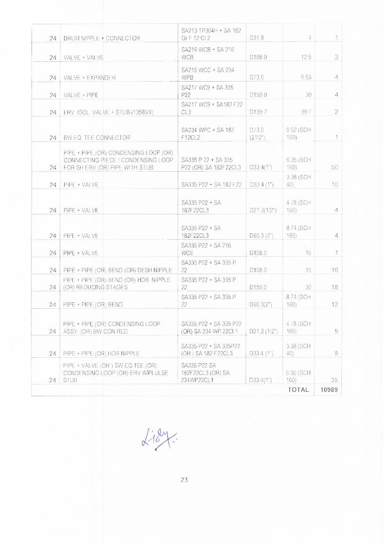
SA213 TP304H + SA 182 Gr.F 12 CL2 D31.8
SA216 WCB + SA 216 WCB D108.0
SA216 WCC + SA 234 WPB D73.0
SA217 WC9 + SA 335 P22 D159.0
SA217 WC9 + SA182 F22 CL3 D139.7
SA234 WPC + SA 182 D73.0 F12CL2 121/2")
SA335 P 22 + SA 335 P22 (OR) SA 182F22CL3 D33.4(1)
SA335 P22 + SA 182 F22 D33.4 (1")
SA335 P22 + SA 182F22CL3
SA335 P22 + SA 182F22CL3
SA335 P22 + SA 216 WC6
SA335 P22 + SA 335 P 22
SA335 P22 + SA 335 P 22
SA335 P22 + SA 335 P 22
SA335 P22 + SA 335 P22 (ORISA 234 WE 22CL1
SA335 P22 + SA 335P22 (OR ) SA 182 F22CL3
SA335 P22 SA 182F22CL3 (OR) SA 234WP22CL1
D21.3 (1 /2")
D33.4 (1")
D33.4(1")
D60.3 (2")
D108.0
D108.0
D159.0
D60.3(2")
D21.3(1/2")
24 DRUM NIPPLE + CONNECTOR
24 VALVE + VALVE
24 VALVE + EXPANDER
24 VALVE + PIPE
24 ERV. ISOL. VALVE + STUB (1358VX)
24 BW EQ. TEE CONNECTOR
PIPE + PIPE (OR) CONDENSING LOOP (OR) CONNECTING PIECE / CONDENSING LOOP
24 FOR SH ERV (OR) PIPE WITH STUB
24 PIPE + VALVE
24 PIPE + VALVE
24 PIPE + VALVE
24 PIPE + VALVE
24 PIPE + PIPE (OR) BEND (OR) DESH NIPPLE
PIPE + PIPE (OR) BEND (OR) HDR. NIPPLE 24 (OR) REDUCING STAGES
24 PIPE + PIPE (OR) BEND
PIPE + PIPE (OR) CONDENSING LOOP 24 ASSY. (OR) BW CON RED
24 PIPE + PIPE (OR) HDR NIPPLE
PIPE + VALVE (OR ) SW EQ TEE (OR) CONDENSING LOOP (OR) ERV IMPLULSE
24 STUB
1
12.5
9.53
30
39.7
9.52 (SCH 160)
1
6.35 (SCH 160)
50
3.38 (SCH 40)
10
4.78 (SCH 160)
8.74 (SCH 160)
4
16
16
16
30
18
8.74 (SCH 160)
12
4.78 (SCH 160)
5
3.38 (SCH 40)
8
6.35 (SCH 160)
35
TOTAL 10989
23

Annexure 'B'
Terms and Conditions for Cranes Provided by Sub contractor
All T&Ps required for successful execution and completion of work shall be arranged and provided by the sub-contractor. Indicative lists of T&Ps and other inputs be arranged by the sub-contractor are given as per Annexure-A3. The subcontractor should ensure that these are in good working condition. In the event of the failure of subcontractor to bring necessary and sufficient T&Ps and other inputs, BHEL will be at liberty to arrange the same and hire charges as applicable shall be deducted from subcontractor's bill. Decision of BHEL in this regard shall be final and binding on subcontractor. The subcontractor shall arrange, at his own cost fuel and other consumables for the operation of the Cranes. (Operator for all the cranes, helpers, fuel and other consumable shall be provided by sub-contractor within the final accepted rates). All lubricants for these cranes such as mobil oil, gear oil, brake oil, hydraulic oil, torque converter oil and grease will be provided by sub-contractor free of cost. The day to day maintenance of Cranes should be carried out by subcontractor as per manufacturer's maintenance schedule at his cost. These shall be maintained in good working condition during the entire period of use. The subcontractor at his own cost shall arrange all supervision and labour required for maintenance of cranes. For attending breakdowns, the contractor shall arrange for labour. Minimum one mechanic and two helpers shall be exclusively marked for the above work. For cranes, replacement of filter and repair of batteries, self, dynamo shall be the responsibility of the subcontractor. (The cranes shall be fitted with a set of new batteries initially)
Increasing / shortening of the crane boom to suit work requirements shall have to be arranged by the indenting subcontractor at his cost. All necessary manpower tools, support, consumables, illumination etc. will have to be arranged by subcontractor at his cost.
1.0
2.0
3.0
4.0
5.0
6.0
24