annex - international energy agency’s energy in ... · iea ecbcs annex 19 handbook a guidebook...
TRANSCRIPT

Annex 19 Technical Synthesis Report
Annex 19 Low Slope Roof Systems
John Palmer
FaberMaunsell Ltd.
Annex 19 Synthesis Report based on: IEA ECBCS Annex 19 Handbook A Guidebook for Insulated Low-Slope Roof Systems
Contributing authors: Vagn korsgaard, Carsten Rode, ~engt-Ake Pettersson, John Harrington-L~wn. John Reid. Jim
Thomson. George Courville. John McCorkle. Thomas Petrie
Published by FaberMaunsell Ltd on behalf of the International Energy Agency Energy Conservation in Buildings and Community Systems Programme

O Copyright Faber Maunsell Ltd 2003
All property rights, including copyright, are vested in the ECBCS ExCo Support Services Unit - ESSU (FaberMaunsell Ltd) on behalf of the International Energy Agency Energy Conservation in Buildings and Community Systems Programme.
In particular, no part of this publication may be reproduced, stored in a retrieval system or transmitted in any form or by any means, electronic, mechanical, photocopying, recording or otherwise, without the prior written permission of FaberMaunsell Ltd.
Published by Faber Maunsell Ltd, Marlborough House, Upper Marlborough Rd, St Albans, Hertfordshire, ALl 3UT, United Kingdom
Document A 19-TSR-2003
ISBN 0-9542670-7-9
Participating countries in ECBCS: Australia, Belgium, CEC, Canada, Czech Republic, Denmark, Finland, Germany, Greece, Israel, Italy, Japan, the Netherlands, New Zealand, Norway, Poland, Portugal, Sweden, Switzerland, Turkey, United Kingdom and the United States of America.
Additional copies of this report may be obtained from:
ECBCS Bookshop C/o Faber Maunsell Ltd 94196 Newhall Street Birmingham B3 1PB United Kingdom

Energy Conserva!ion in Bnildings and Commtmi/y Systems
Preface
International Energy Agency
Thc International Energy Agency (IEA) was established in 1974 within the framework of the Organisation for Economic Co-operation and Development (OECD) to implement an interna- tional energy programme. A basic aim of the IEA is to foster co-operation among the twenty- four IEA participating countries and to increase encrgy security through encrgy conservation, development of altcrnative energy sources and energy rescarch, dcvclopment and demonstration (RD&D).
Energy Conservation in Buildings and Community Systems
Thc IEA sponsors rcsearch and dcvclopment in a number of areas related to encrgy. The mis- sion of one of thosc areas, the ECBCS - Energy Conservation for Building and Community Sys- tems Promamme. is to facilitate and accelerate the introduction of enerm conservation. and cn- - -. vironmentally sustainable technologies into healthy buildings and community systems, through innovation and research in decision-making, building assemblies and systems, and commerciali- sation. The objectives of collaborative work within;he ECBCS ~ & d ~ r o ~ r a m are directly de- rived from the on-going energy and environmental challenges facing IEA countries in the arca of construction, energy market and research. ECBCS addresses major challenges and takes ad- vantage of opportunities in thc following areas:
exploitation of innovation and information technology; impact of energy measures on indoor health and usability; integration of building energy measures and tools to changcs in lifestyles, work cnvi- ronment alternatives, and business environment.
The Executive Committee Overall control of the program is maintained by an Executive Committce, which not only moni- tors existing projccts but also idcntifics new areas where collaborative effort may be beneficial. To datc the following projects havc bcen initiated by the executive committee on Energy Con- servation in Buildings and Community Systems (completed projects are identified by (*) ):
Annex I : Annex 2: Anncx 3: Anncx 4: Anncx 5: Annex 6: Anncx 7: Annex 8: Annex 9: Annex 10: Annex I I : Annex 12: Annex 13: Annex 14: Annex 15: Annex 16: Annex 17: Anncx 18:
Load Energy Determination of Buildings (*) Ekistics and Advanced Community Energy Systcms (*) Energy Conservation in Residential Buildings (*) Glasgow Commercial Building Monitoring (*) Air Infiltration and Ventilation Centrc Encrgy Systems and Design of Communities (*)
Local Govcrnmcnt Energy Plaming (*) Inhabitants Behaviour with Regard to Ventilation (*) Minimum Ventilation Rates (*) Building HVAC System Simulation (*) Energy Auditing (*) Windows and Fenestration (*) Energy Management in Hospitals (*) Condensation and Energy (*) Energy Efficiency in Schools (*) BEMS 1- User Interfaces and System Integration (*) BEMS 2- Evaluation and Emulation Techniques (*) Demand Controlled Ventilation Systems (*)

Annex 19 Low Slope RoofSyslems
Annex 19: Annex 20: Annex 2 1 : Annex 22: Annex 23: Annex 24: Annex 25: Annex 26: Annex 27: Annex 28: Annex 29: Annex 30: Annex 31: Annex 32: Annex 33: Annex 34: Annex 35: Annex 36: Annex 37: Annex 38: Annex 39: Annex 40: Annex 4 1 : Annex 42:
Annex 43:
Low Slope Roof Systems (*) Air Flow Patterns within Buildings (*) Thermal Modelling (*) Energy Efficient Communities (*) Multi Zone Air Flow Modelling (COMIS) (*) Heat, Air and Moisture Transfer in Envelopes (*) Real time HEVAC Simulation (*) Energy Efficient Ventilation of Large Enclosures (*) Evaluation and Demonstration of Domestic Ventilation Systems (*) Low Energy Cooling Systems (*) Daylight in Buildings (*) Bringing Simulation to Application (*) Energy-Related Environmental Impact of Buildings (*) Integral Building Envelope Performance Assessment (*) Advanced Local Energy Planning (*) Computer-Aided Evaluation of HVAC System Performance (*) Design of Energy Efficient Hybrid Ventilation (HYBVENT) (*) Retrofitting of Educational Buildings Low Exergy Systems for Heating and Cooling of Buildings (LowEx) Solar Sustainable Housing High Performance Insulation Systems Building Commissioning to Improve Energy Performance Whole Building Heat, Air and Moisture Response (MOIST-ENG) The Simulation of Building-Integrated Fuel Cell and Other Cogeneration Systems (GOGEN-SIM) Testing and Validation of Building Energy Simulation Tools
(*) - Completed Annexes
Annex 19 Low-slope Roof Systems
Summary The need for energy efficiency has increased the amount of insulation required, and for well- insulated low-slope roofs this has increased the demand for information on design, installation, and maintenance needs. A primary purpose of this Annex was to assess and report on the cur- rent roofing practices in the context of an accumulating database on performance.
Annex 19 'Low-slope roof systems' completed its work with a report entitled 'A Guidebook for Insulated Low-slope Roof Systems', published in February 1994. The objective of the report was to describe available information and good practice when working with highly energy effl- cient low-slope roof systems. The report describes the various types of low-slope roof and the insulating materials that may be used. The requirements of the various construction methods and insulation combinations are discussed on the context of possible modes of failure. Examples of successful methods are provided.
Participating countries The participating countries in this task were: Sweden, Denmark, UK, USA (Operating Agent)

Energy Conservation in Buildings and Community Systems
Contents
1. Introduction
1. I Insulation Types, Coverings and Roof Systems I . 1.1 Generic lnsulation Types 1.1.2 Polyisocyanurate or Polyurethane Foam 1.1.3 Mineral Wool - High Density 1.1.4 Mineral Wool - Low Density 1.1.5 Polystyrene 1 . I .6 Fibreboard 1.1.7 Perlitic Board 1.1.8 Corkboard 1 . I .9 Cellular Glass 1.1.10 Lightweight Insulating Concrete Deck and Fill
1.2 Waterproof Coverings 1.2.1 Bituminous Membranes 1.2.2 Mastic Asphalt (Asphaltic Cement) 1.2.3 Elastoplastic Polyrncr Membranes 1.2.4 Metal Roofing 1.2.5 Liquid, Spray-Applied Membranes I .2.6 Brush- and Roller-Applied Systems
1.3 Common Insulated Roof Systems 1.3.1 Warm Deck Systems - Single Type of lnsulation 1.3.2 Warm Deck Systems - Multiple Types of lnsulation 1.3.3 Cold Deck Systems 1.3.4 Metal Roof Systems 1.3.5 Protected Membrane Systems 1.3.6 Spray-Applied Polyurethane Foam Systems.
2. Good Practices for Insulated Roofs
2.1 Design Issues 2. I . 1 Optimum Thermal Eficiency 2.1.2 Surface Temperature of Low-Slope Roofs 2.1.3 Interior Moisture 2.1.4 Drainage 2.1.5 Fire Resistance 2.1.6 Wind Resistance
2.2 Maintenance lssues
3. lnsulation Related Roof Problems
3.1 Mechanical Problems 3.1.1 Membrane Splitting Over lnsulation 3.1.2 Flashing Pull-Away and Membrane Splitting Around Fasteners
3.2 Physical and Chemical Degradation 3.2.1 Corrosion of Metal in Roofing Systems 3.2.2 Physical Deterioration of Insulations 3.2.3 Research Needs
Annex 19 Low Slope Roof Systems
3.3 Shortfalls From Design Thermal Performance 3.3.1 Thermal Bridging 3.3.2 Thermal Drift of Insulation 3.3.3 Research Needs
3.4 Moisture Intrusion and Effects of Retention 3.4.1 Membrane Blistering 3.4.2 Localised Ponding and Freezing of Pools of Water 3.4.3 Roof Leak Detection and Correction 3.4.4 Condensation Effects from Trapped Water 3.4.5 Diurnal Hygrothermal Cycling
4. Example Roof Systems
4.1 Warm Deck Systems: Single Type o f Insulation 4.1.1 New Construction 4.1.2 Reroofing Over an Old Warm Deck Roof 4.1.3 Reroofing Over an Old Cold Deck Roof
4.2 Warm Deck Systems: Multiple Types o f Insulation 4.2.1 Insulation with Coverboard 4.2.2 Three-Layer System
4.3 Cold Deck Systems 4.3.1 Conventional Cold Deck System 4.3.2 Raised Cold Deck Roofs
4.4 Metal Roof Systems 4.4.1 New Roof 4.4.2 Reroofing
4.5 Protected Membrane Systems
4.6 Spray-Applied Foam Systems
References

1. Introduction
Low slope roof systems are common on commercial and industrial buildings and, to a lesser extent, on residential buildings. Although insulating materials have nearly always been a com- ponent of low-slope roofs, the amount of insulation used has increased in recent times because of increased energy costs and the need to reduce carbon emissions. As the amount of insulation has increased the demand for design, installation, and maintenance information has also in- creased, specifically for well-insulated roofs.
Many design and installation issues have been resolved by the industry but still some contrac- tors and building owners attribute roofing problems to the additional insulation. It was the inten- tion of this IEA Task to study the perceived correlations between roofing problems and the ad- dition of insulation, to examine their factual basis, to discuss remedial measures, and to define the research needed to resolve significant outstanding issues. Performance information and il- lustrative roof systems for all the participating countries were studied.
The roof of a building has several basic functions: prevention of ingress of water . thermally isolate the building from the environment accommodate motion of the building . accept foot-traffic and service penetrations resist wind loads limit the spread of fire.
As no single material can perform all these functions a roof is a composite of several materials, all of which must perform together as a system. This concept of the roof as a system has been a major contribution to recent roofing studies. Understanding this has underpinned this IEA study which not only provides information on insulation as a roofing material but also emphasises it as a component of the roof system.
With a properly designed roof, the most noticeable benefits of increasing insulation are reduced operating costs and improved occupant comfort. Although the effects are greatest on a single storey building even for a three storey building the roof can represent more than 50% of the ex- posed surface.
Currently, most nations have recommended minimum levels of insulation for low-slope roofs. Often these are backed up by specific regulations. However, while minimum levels are thus clear, the optimum level results from a trade-off between the added first cost for the insulation and the savings in future operating costs. Life cycle costing is most appropriate for making this analysis and would suggest that, for example, for harsh climate zones in the US 80mm of min- eral wool is optimum, whereas in Scandinavia, 200mm would be optimum, with a value be- tween these for the UK.
Calculating the heating and cooling costs attributable to the roof should always be part of the building design process. To do this a suitable mathematical model should be used. This may vary from a simple steady-state model through to a fully dynamic simulation of the heat flows.
The addition of insulation to the roof system may place the system at an increased risk of me- chanical failure. Insulation added between the deck and the membrane tends to isolate the mem- brane from the deck. One consequence of this is that the mechanical stresses applied to the membrane, for example from the perimeter wall, are not as readily transferred to the deck. Thus the membrane will move more when thermally stressed, which ultimately increases the potential

Energy Conservation in Buildings and Communily Systems
for membrane fatigue. Similarly, severe thermal stresses can be induced by greater temperature variations resulting from the insulation.
Moisture problems can also be exacerbated by insulation as the increased membrane movement increases the risk that leaks will develop, particularly at edges or penetrations. In addition, mois- ture can move laterally within the insulation and the leak can be quite large before a problem is noticed inside the building.
1.1 Insulation Types, Coverings and doof systems
Before describing good roofing practices and issues in relation to insulated roof systems, it is worthwhile to introduce briefly the materials and systems that will be discussed in this report.
1.1.1 Generic Insulation Types The following section of this report outlines the properties of the main insulation materials used in roof systems. Table 1 shows typical relative material property values for most common roof insulations (where available, the information is quantitative - in SI units).

C Annex 19 Low Slope RoofSystems
Table I . Material properties of common roof insulations.
Property
Fire resistance Closed cell content (%) Compressive strength (kPa) Damage t?om freezelthaw (visual) Damage from heat (visual) Damage from water soak (visual) Density (may includc
Mineral wool low density
Yes 0
Low NF
facer) (kg/m3) Dimensional stability Flexural strength Friability
NF Low
10-25
~ ~ - -
Interlaminar shnmgth I Low I Low I Low I Mod. High High ~ i ~ h
[W(m.K)~' ] Thermal expansion I 9-14 I 9-14 I N A I 5 1 54.140 1 63 1 63 I 90 I 8
Mineral wool high density
Yes 0
70 NF
NF Low NF
- - - - - - - --
High r High
coefficient (IO.~.C?) Thermal resistance (perm) I 25 I 28 I 19 I 19 I 4 1 I 26-35 I 26 I N A 1 18
NF Mod.
110-160
- - ~ - ~ - ~ , ~ - - ~ ~ ~ ~ , 4 . . . .
Specific heat [kJ(kg.K)"] I 0.84 1 0.84
Perlitic
Yes 0
170-210 NF
NF Low NF
. ..
1.05 NF
0.062 Thermal aging 1 NF
KEY to entries: NF - not a factor: NA-not available: Slight - less than low but not negligible: Qualified - acceptable with conditions (see manufacturer's literature) " Aged thermal conductivity of a polyisocyanurate foam depends upon facers. ASHRAE 1989, p.227, shows 0.020W(m.K) for gas-impermeable facers and 0.25 w ( ~ . K Y ' for no facer.
NF High
130-160
Moisture expansion
NF
- [M(K.w)-'1 Water vapour permeability kg(~a.K.m)-'1 Water absorption
Wood tibre- board Yes
0 N A NF
NF 310-380
High
Solvent resistance (visual) I NF I NF I NF I NF I NF 1 T nw I T nw I NF NF Low
Thermal conductivity 0.039 I 0.036
NF High
240-320
Slight . .. . ..
1.38 1 1.59
High
High
Polyiso- cyanurate
Yes 90-95% 120-140
NF
NF N A
s i g h t
Slight 1 Slight I High Low
1.13 NF
0.029 NF
Slight Low
32
Low
110
High
Extruded polystyrene Qualified 90-95% 90-690
NF
Good N A NF
Low -- ..
1.13 NF
0.038 0.052 / 0.020-0.025"
High Slight
18-48
Low 1 NF
30-35
High
Expanded polystyrene Qualified 90.95%
80 NF
Good 210-690
Slight
. .. N A
Slight 0.017
High Low
16
. .- 0.75 NF
0.055
30-35
High
Phenolic foam Yes
90.95% 170 NF
Good 170-210 Slight
Cellular glass Yes
100% 690 Low
Slight Low
40
3
Low
NF NF
136
Good N A Low
NF 450-520
High
2-5
Low
N A
Low
3
Low
0
NF

Anner 19 Low Slope Roof Systems
1.1.2 Polyisocyanurate or Polyurethane Foam Polyisocyanurate (PIR) and polyurethane (PUR) foam roof insulations are closed-cell foams that were blown with CFC gas at the time of reporting the Task. The chemicals used for PIR and PUR foam are almost identical except for the chemical ratios and catalyst types. The catalyst chemistry and processing temperature differences produce polymers that resist tire differently, affecting fire performance. The chemistry of PIR foam makes it more suitable than PUR for use directly over steel roof deck as it can be used without the need for a relatively expensive fire barrier separation. Therefore it is more widely used. PIR blown with CFC has the best thermal resistance per unit thickness of all major commercial roof insulations but is susceptible to aging as air diffuses into the material and replaces the CFC.
1.1.3 Mineral Wool - High Density Mineral wool roof insulation is a rigid insulating material in board form composed of mineral wool and a thermosetting binder. The fibres are formed by spinning from either molten glass (sand, limestone, and soda ash) or molten rock (basalt and limestone). The binder is usually phenolic resin. The material is made into boards that can be unfaccd or, to allow asphalt mop- ping for BUR (built-up roof) systems, it can have a top surface trcatmcnt. The inorganic, fibrous nature of this product provides fire resistance, good dimensional stability, and conformance to roof-deck irregularities but long term exposure to watcr causes sufficient detcrioration to war- rant replacement. It is also limited by its low compressive strength although special form can be produced to improve this characteristic.
1.1.4 Mineral Wool- Low Density Low density mineral wool blankets and batts are made similarly to high density materials, but the final product has a density of about 10-25 kgim\ather than the 1 I0 to 145 kgim' of the high density product. These products can be used for roof insulation if they are installed below a roof deck. They have the advantage of lower cost per unit of insulation R-value than above deck roof insulation when open, accessible deck framing is available.
1.1.5 Polystyrene Polystyrene foam roof insulation is a rigid, closed-cell foam supplied in board form. Two dis- tinctly different types are commercially available:
molded expanded polystyrene (EPS) extruded expanded polystyrene (XPS).
The two types have significantly different properties and costs, which affect the way they are used in roof systems. In situations where insulation costs must be low EPS is preferred because it costs roughly half as much as XPS.
1.1.5.1 Molded Expanded Polystyrene(EPS) This product has a nominal density of 16 to 20 kgim' when used in roofs. EPS generally has the lowest cost per unit of insulating value of any above-deck insulation, but the installed cost de- pends on the need for a fire retarder as a top or bottom board for some deck and membrane sys- tems. The thermal conductivity of EPS does not change with age because it does not contain CFC gas. Its combustibility is a significant limitation, even though it is manufactured with a fire-retardant additive.
1.1.5.2 Extruded Expanded Polystyrene (XPS) Extrusion provides XPS with significantly better water resistanec than EPS and the insulating value per unit thickness can be as much as 20% better than EPS because XPS is blown with low-conductivity CFC gas.

Energy Conservation in Buildings and Community Systems
1.1.6 Fibreboard Fibreboard roof insulation has been used for many years in the United States. It is a rigid, cellu- losic board product, composed of interlocking wood or cane fibres and water resistant binders. It has a price advantage over mineral wool but its high thermal conductivity suits it more to low thermal performance roofs. As a primary insulation its use has decreased but it is increasingly used as a low-cost coverboard over organic foams.
1.1.7 Perlitic Board Perlitic board roof insulation is a homogeneous, rigid, insulating material composed of ex- panded volcanic mineral particles (perlite), some recycled organic fibre, and a waterproofing additive. The high perlite content of this product provides good fire resistance and good dimen- sional stability. Its relatively low strength makes it prone to handling damage and wind damage and its poor water resistance can lead to permanent structural and thermal degradation. As with fibreboard it can be used in combination with organic foams when its fire resistance can be used to advantage.
1.1.8 Corkboard Corkboard insulation is a natural material that can be either bitumen bonded or mechanically fixed with screws and washers to the roof deck. It is suitable for metal and other decks. No CFC gases are used in the manufacture and natural binders present in the cork are sufficient to bind the granules together into a single unit. It is friable and therefore liable to damage from rough handling but when used with appropriate decks and finishes has unrestricted use with respect to fire regulations in the UK.
1.1.9 Cellular Glass Cellular glass is the only inorganic, closed-cell roof insulation in the market-place. It is pro- duced by foaming molten glass at approximately 510°C with an inert gas. The finished molded product is available either with or without krafi paper facers. It is durable, dimensionally stable, highly fire resistant, and highly water resistant. Its thermal conductivity is poor compared with closed-cell CFC-blown organic insulation and it is also relatively costly for equivalent thermal performance compared with other roof insulation products.
1.1.10 Lightweight Insulating Concrete Deck and Fill Lightweight insulating concrete is a cementitious deck insulation and roofing substrate pro- duced by combining lightweight insulating aggregates, such as perlite, vermiculite, or expanded clay clinker, with Portland cement and water. Some types are made simply by blending pre- generated foam with Portland cement and water. All of these are applied in a liquid form and are screeded to provide a smooth roofing substrate. The relatively poor insulating value of light- weight concrete makes it necessary to incorporate additional insulation for high thermal per- formance. This is done in the United States by incorporating foam polystyrene board insulation into the wet lightweight insulating concrete when it is being poured.
1.2 Waterproof Coverings
The primary function of waterproof coverings is to provide a durable, water-tight barrier for the top of a building. This function includes a permanent water seal around all projections through the roof surface, long-term resistance to all weather and climate exposure conditions, and ac- commodation of movement by the building's structure without rupture. Generic types of water- proof coverings include:
bituminous membranes . mastic asphalt . elastoplastic polymer membranes
Annex 19 Low Slope Roof Syslems
. metal roofing . liquid, spray applied membranes.
1.2.1 Bituminous Membranes Bituminous membranes are composed of layers of waterproofing bitumen (asphalt or coal tar pitch) rcinforced with one or more layers of felt. Traditionally, these membranes have been called 'built up roofs' (BUR) because they are fabricated on thc roof by adhering layers of fac- tory-impregnated felts with hot bitumen. Surfacings are used to improve resistance to fire, roof traffic, hail and ultraviolet light.
Waterproofing bitumens with improved elasticity to accommodate roof stresses have been de- veloped by adding synthetic polymers to the bitumen. These polymer modified bitumens are being incorporated into factory made 'modified bituminous membranes' that are in effect com- plete pre-fabricated membranes ready for installation on roofs.
1.2.2 Mastic Asphalt (Asphaltic Cement)
The UK has a well established and successful history of the use of mastic asphalt as a roof cov- ering. This material is a mixture of suitably graded aggregates bound with refined bitumen. The combination results in a dense coating with no voids that is spread out over a roof in two or three coats to a final thickness of 20-25mm. The result is a membrane that is fully waterproof and very durable. Examples of mastic roof are available that have survived for 50 to 100 years with little maintenance. However, these roofs are uninsulated and subject to 'thermal shock' failurc. Recently, polymer modified mastic asphalt has been developed to resist thermal stress and improve durability.
1.2.3 Elastoplastic Polymer Membranes
These membranes are factory produced from plastic or elastic polymeric compositions. They are highly durable under the stresses of insulated roof conditions because of long-term flexibility at low temperatures and stability at elevated roof temperatures. They are relatively thin (1.0 to 1.5mm) and are normally applied as a single ply, which can be installed quickly and is lighter in weight than most alternative systems. They require mechanical attachment or loosely laid bal- last to add wind resistance and in single ply systems the lap sealing is critical.
The most commonly used wlcanised elastomer is EPDM, typically used without reinforcement whereas the most common nonwlcanised is chlorosulfonated polyethylene (CSPE). This is eas- ier to seam on the roof than EPDM.
Polyvinyl chloride (PVC) is the most commonly used thermoplastic membrane material. It has good flame resistance, and permits solvent or heat welded seams for original installation and repair. They are incompatible with bituminous materials and must be isolated from them in roof systems.
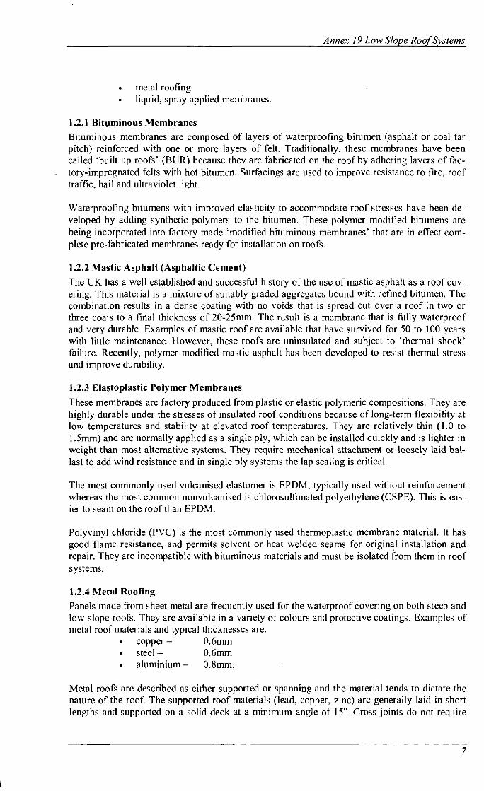
1.2.4 Metal Roofing Panels made from sheet metal are frequently used for the waterproof covering on both steep and low-slope roofs. They are available in a variety of colours and protective coatings. Examples of metal roof materials and typical thicknesscs are:
copper - 0.6mm steel - 0.6mm aluminium - 0.8mm.
Metal roofs are described as either supported or spanning and the material tends to dictate the nature of the roof. The supportcd roof materials (lead, copper, zinc) are generally laid in short lengths and supported on a solid deck at a minimum angle of 15". Cross joints do not require

Energy Conservalion in Buildings and Community Systems
sealant and can be either cross welted or simply overlapped. Successful leak-free performance of metal roofing on lower slopes is critically dependent on the design and application quality of seam (jointing) details, flashings at roof penetrations (fixing holes), and substructure attachment to accommodate substantial thermal expansion and contraction. A wide range of surface coat- ings is available from zinc to PVC and PVFI.
1.2.5 Liquid, Spray-Applied Membranes Spray-applied membranes employ fluid asphaltic or elastomeric water-proofing compositions and are installed at ambient temperature. They are commonly classified as cold-applied mem- branes. The asphaltic membranes always contain reinforcing fabrics. Elastomeric spray-applied membranes do not incorporate reinforcing fibres or felts and are normally installed over spray- applied PUR foam insulation. This system forms a continuous, self-flashing insulated mem- brane.
1.2.6 Brush- and Roller-Applied Systems
A number of glass-fibre reinforced resin systems are in use in the UK. They are applied by roll- ing the base coat onto a prepared plywood deck then imbedding the glass-fibre mat into the freshly laid resin by further rolling.
1.3 Common Insulated Roof Systems
The following roof systems are representative of those most commonly used in the countries participating in this IEA annex. All systems are shown with vapour retarders that prevent build- ing generated moisture diffusing into the roof system - these may not be necessary in warm cli- mates.
1.3.1 Warm Deck Systems - Single Type of Insulation
Conventional warm deck systems have insulation installed over the roof deck and under a wa- terproof covering. Systems employing a single type of insulation are easy to install and eco- nomical. The concrete deck example below is common for new construction and is only one of many possible combinations - including reproofing over an existing warm roof or over an old cold deck system.
Figure I . A common warm roof deck system with a single type of insulation.
1.3.2 Warm Deck Systems - Multiple Types of Insulation
Multiple types of insulation may be needed in some roof systems because of the range of func- tions required of the insulation. The figure below shows a system used successfully in the UK.

Annex 19 Low Slope Roof Systems
Figure 2. A warm deck roof with two insulations. The coverboard is a more acceptable sub- strate for mastic asphalt than the mineral wool primaiy insulation.
The high energy efficiency required of modern roof systems can result in three types of insula- tion beine installed. with a oerlite bottomboard over a steel deck to provide fire protection for the EPS i&lation.
r
Figure 3. A three-insulation warm deck roof system. Some high-thermal performance foam in- sulations are sensitive fo bitumens on the top and cannot meet fhefire code over metal deck.
1.3.3 Cold Deck Systems
These are attractive economically, because they allow the use of low-density, low-cost mineral wool insulation. The figure below illustrates this type of system.

en erg^ Conservafion in Buildings and Communip Systems
Figure 4. A cold deck roof system. Care must be taken to minimize water condensalion on the underside of the deck.
1.3.4 Metal Roof Systems Metal roof systems employ seamed metal panels to form waterproof coverings. The tigure shows a typical system with insulation installed over a metal deck and structural standing seams.
Figure 5. A metal roof .y tem. This example depicts a "strudural standing seam" or "secrer fix" metal rooj:
Metal roofing can be used to re-roof over any type of old roof membrane or roof deck type.
1.3.5 Protected Membrane Systems A protected membrane system is a special warm deck system in which the insulation is located on the weather side of the waterproof membrane. Normally XPS is used as its thermal perform- ance is not affected by the service conditions.
1.3.6 Spray-Applied Polyurethane Foam Systems Spray applied PUR foam roofing is a monolithic, seamless, self-flashing system consisting of foamed-in-place insulation covered with a spray applied elastomeric membrane coating. It can be installed on a range of deck materials and for reproofing old roofs.

2. Good Practices for Insulated Roofs
When choosing the type and amount of insulation and the method to incorporate it into a roof system, one should be aware of the implications of this choice on other characteristics of the roof. Problems can result from increased membrane stress, moisture storage, reduced resistance to wind uplift, and increased fire hazard. For most problems, remedies have been identified and are part of standard good practice.
2.1 Design Issues
2.1.1 Optimum Thermal Efficiency
lnsulation in low-slope roofs improves thermal efficiency and reduces the heating and cooling load on a building. This has a direct impact on the cost of operating the building but accurate in- service performance data must be available for realistic assessments to be made of these sav- ings. For each of the participating countries sources of suitable information were obtained. From the Swedish Building Code there is extensive information (Petersson 1981; Petersson 1990; Petersson 1992) about how to correct the thermal performance of a roof system using XPS as a function of a number of effects due to moisture and weather in the context of the Swedish climate.
Using this type of information to predict the energy savings, and using the costs of installing the insulation the true life-cycle costs of insulation can be determined. This approach can then be used to determine the optimum thickness of the insulation for the building in question. This has been done for regions of the United States (DOE 1989) as shown below in Table 2.
Table 2. Optimum thermal insulation thicknesses for life-cycle cost minimisation
Insulation
'These calculations are typical only of US. conditions. In Scandanavia, with harsher climates and higher energy prices, a typical thickness of mineral wool is 200mm. Mandatory 1981 standards in Scandanavia call for 125mm in new housing.
Economic optimum thermal insulation thickness (mm)" Mild U.S. climates I Harsh U.S. climates (Alaska
Fibrous glass Expanded polystyrene Polyisocyanurate
These optimum thicknesses are largely independent of the insulating material use because of the relationship between the thermal resistance and cost of the materials. The more costly materials tend to have a better thermal performance per unit thickness.
2.1.2 Surface Temperature of Low-Slope Roofs
32 39 32
The solar absorptance of the roof membrane plays a dominant role in determining the daytime temperature of a roof. On a bright summer day, the temperature of a membrane with a solar ab- sorptance of approximately 0.9 can easily exceed 70°C, and the surfacc temperature of a mem- brane with a solar absorptance of approximately 0.5 on a similar roof under similar conditions may not exceed 50°C.
not included) 77 99 77
Energy Conservation in Buildings and Community Systems
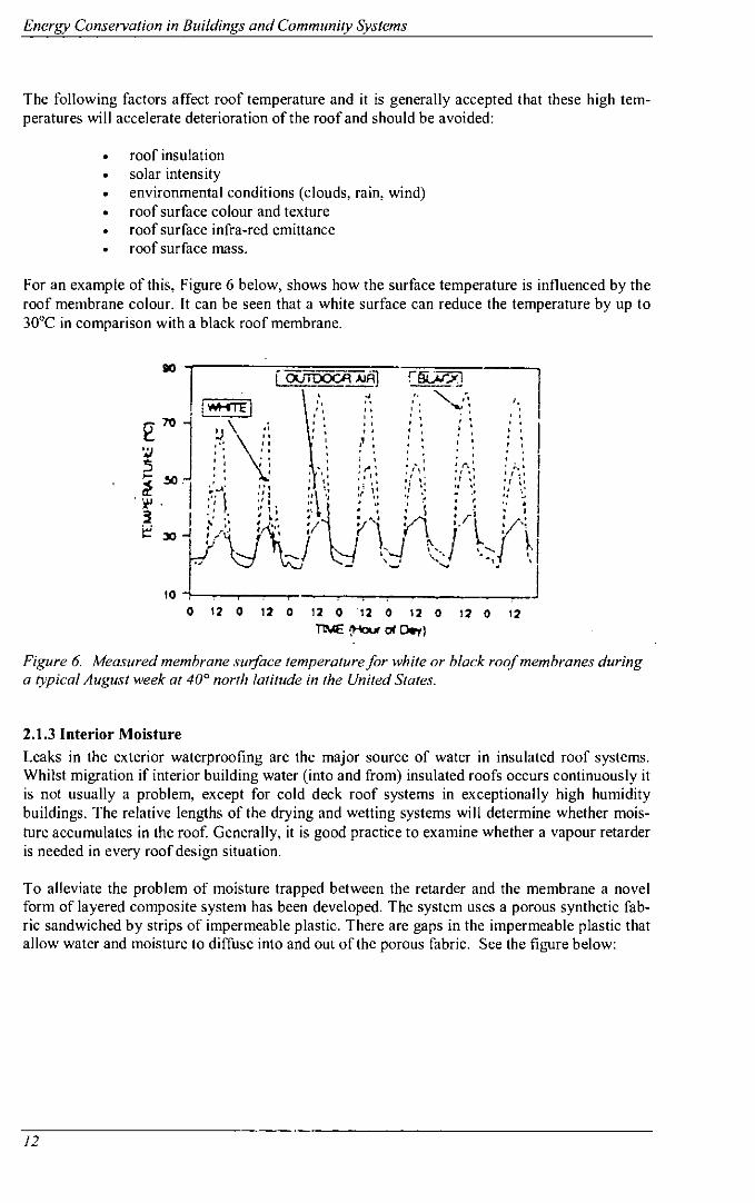
The following factors affect roof temperature and it is generally accepted that these high tem- peratures will accelerate deterioration of the roof and should be avoided:
roof insulation solar intensity environmental conditions (clouds, rain, wind) roof surface colour and texture . roof surface infra-red emittance roof surface mass.
For an example of this, Figure 6 below, shows how the surface temperature is influenced by the roof membrane colour. It can be seen that a white surface can reduce the temperature by up to 30°C in comparison with a black roof membrane.
Figure 6. Measured membrane surJ/ace temperature for white or black roqf membranes during a typical August week at 40° north latitude in the United States.
2.1.3 Interior Moisture Leaks in the exterior waterproofing are the major source of water in insulated roof systems. Whilst migration if interior building water (into and from) insulated roofs occurs continuously it is not usually a problem, except for cold deck roof systems in exceptionally high humidity buildings. The relative lengths of the drying and wetting systems will determine whether mois- ture accumulates in the roof. Generally, it is good practice to examine whether a vapour retarder is needed in every roof design situation.
To alleviate the problem of moisture trapped between the retarder and the membrane a novel form of layered composite system has been developed. The system uses a porous synthetic fab- ric sandwiched by strips of impermeable plastic. There are gaps in the impermeable plastic that allow water and moisture to diffuse into and out of the porous fabric. See the figure below:

Annex 19 Low Slope Roof Sy.stems
Figure 7. The water-permeable vapor retarder (hygro diode), a novel concept for moisture management in roofsystems.
Interior moisture can be a serious problem in cold-deck systems as the moisture can condense on the underside of the deck. Generally, this can only be solved by careful sealing with a vapour retarder, and by providing ventilation to the cold s i d e even by mechanical ventilation.
2.1.4 Drainage Providing positive drainage by slopes in the range 1 :48 to 1 :24 is cost effective on a life cycle basis.
. Increasing the slope of entire BURS during replacement is more costly than re- placement to the original slope and may not be cost effective on a life cycle basis. However, most roof leak problems involve flashings, and provision for good drain- age around flashings is beneficial.
. Conversion of smaller buildings from BUR to a watershed system (metal or shin- gle) can be competitive on an initial cost basis with BUR replacement when re- roofing involves an upgrade in thermal performance.
Good drainage can be achieved in several ways on both new and old roofs. The structural deck can be tapered when a roof is being built either by varying the column height or, in the case of poured concrete, by varying the thickness of the pour. A full taper over the entire roof is prefer- able but may require a significant increase in the height of roof perimeters and curbs and reloca- tion of drains.
Ponding on existing roofs indicates the need to look for more serious building problems such as foundation settlement or permanent structural deflections. Most roof leaks occur at roof details and flashings, therefore the designer must prevent ponding in these areas. All roofs should have saddles for slope between valley drains, tapers into drain sumps, added roof thickness (crickets) in flat corners and along the high side of long kerbs, and perimeter edge tapers for roofs with interior drains. Dividers on large roofs will limit the spread of water damage in the event of leaks.
2.1.5 Fire Resistance Roof insulation significantly increases the complexity of design to comply with building code and insurance requirements, related to both exterior and interior fire sources. Organic foam in- sulations have flammability and membrane compatibility problems and other insulation types need to be placed under polystyrene and PIR foam insulations for bottom-side fire protection over steel decks as well as combustible decks. Top-side fire protection barriers (perlite mineral wool, or wood fibreboard) are normally required over polystyrene and PUR foam insulations

Energy Conservrrlion in Buildings rrnd Communiv Systems
when they are used with un-ballasted elastoplastic single-ply membranes. These top-side barri- ers also protect against high temperatures from asphalt melting or solar radiation.
2.1.6 Wind Resistance Wind damage can occur suddenly and is often accompanied by rain, which causes further dam- age to the building. Increasing the insulation in roofs brings with it a number of edge detailing and attachment issues that can increase the vulnerability of the roof to damage by the wind. Pre- dicting roof performance in storms is too inexact for reliable design. Fully adhered or mono- lithic roof systems offer the most wind protection although weak bonding of laminated systems may fail under uplift conditions.
Mechanical fasteners are a common method of attachment for insulated roof systems over 'nail- able' decks. Short fastenings are favoured when using two layers of insulation and the first layer in mechanically attached to the deck and the second layer fixed to the first with an adhesive. This avoids thermal bridging and damage by foot traffic. Air barriers protect against uplift forces - a poured concrete deck is an excellent air barrier.
2.2 Maintenance Issues
All roofs require periodic maintenance for a long life but this is often overlooked or neglected and costly repairs or replacement can be the result. A regular inspection and maintenance pro- gramme should be carried out by the proper personnel and if done this will add years to the life of the roof. Most roof leaks involve flashing deterioration, puncture damage, or membrane lap defects, and are initially limited to a small percentage of the total roof area. Thus they are rela- tively inexpensive to repair if detected early. Roof traffic is a maintenance issue and clear path- ways should be provided.
Maintenance issues should be addressed at the design stage and the requirements also need to be passed on in the case of a change of ownership.
Twice yearly inspections by a trained roof inspector can spot most problems visually and these should be acted on swiftly. Emergency repairs should be made good after locating the cause of the initial problem. This may require the services of an expert in non-destructive testing proce- dures but removal of wet insulation is vital to avoid further damage to the roof.

Annex 19 Low Slope Roof Sy.siem.s
3. Insulation Related Roof Problems
3.1 Mechanical Problems
3.1.1 Membrane Splitting Over Insulation
Statement of the Problem Membrane splitting is a localised, often sudden, rupture of a roofing membrane that develops when induced stress causes the differential strain to exceed the limits of the membrane material in place on its substrate. Insulation contributes to membrane splitting because it isolates the membrane both thermally and mechanically from the structural substrate. The thermal isolation exposes the membrane to greater temperature fluctuations and thereby increased stresses from contraction and expansion.
Evidence The field studies showed that BUR membrane splitting depends on deck type, length of span between steel deck bar joist supports and the grade (ductility) of the asphalt in the roofing membrane. Splitting problems with unreinforced PVC membranes were identified as excessive shrinkage and embrittlement of the membrane by UV rays. Laboratory evidence led to the specification of the 'thermal shock resistance' as a minimum tensile strength of 1380 kPa at - 18% and this was widely accepted by the roofing industry. This was achieved by glass- reinforced BUR and gave excellent performance. Subsequently, some polyester fibre reinforced membranes performed well despite not meeting the 1974 criteria. (NRCA undated, Rosenfield (1981), NIST).
Analysis The severity of splitting problems with BUR reduced from the many lawsuits against roofing contractors in the 1960s and 1970s to few problems when installed in accordance with NRCA recommendations. These incorporate the following:
. NBS Building Science Series 55 membrane tensile strength recommendation (1974)
NBR NBSlR 86-3418 strain enerev and wateroroofness recommendations -2
(1986) . FM loss prevention data sheet 1-28 (requiring mechanical attachment of roof . . - systems over steel decks)
FM loss prevention data sheet 1-52 (prescribing a field test procedure for wind uplift with both new roof construction and reproofing)
Successful field experience confirms that corrective remedies are adequate. Splitting problems of fibreglass reinforced BUR are minimal and modified asphalt products are regarded as supe- rior flashing and repair materials. Splitting of unreinforced PVC membranes has been largely overcome by using more durable plasticisers and membrane reinforcement.
3.1.2 Flashing Pull-Away and Membrane Splitting Around Fasteners
Statement of the Problem Problems with flashing pull-away and membrane splitting around fasteners can be caused either by lack of dimensional stability in the membrane or the roofing felt or by insufficient compres-

Energy Conservation in Buildings and Communiv Systems
sion strength in the insulation material. The importance of the later has increased with the in- crease in thickness of insulation and the resulting use of long mechanical fasteners.
Evidence The increased thickness of compressible insulation (up to 200mm in Denmark) has led to some serious problems. Foot traffic over the roof can cause significant problems with such thick lay- ers of compressible insulation:
deformations of more that 15 to 20 mm . pressing the fastener heads against the membrane leading to underside membrane puncture . bending fastener plates leading to tearing membranes . stripped threads in metal decks . compression should not exceed 4% or 12mm.
Analysis In Europe the problem of membrane splitting round fasteners does not appear to be severe. Manufacturers have modified their products accordingly, producing telescopic fasteners for soft mineral wool insulation. In the US locking plate fasteners have been introduced to reduce the problem with thick, soft insulation.
There are a number of available remedies with guidance from UEAtc guidelines and hardware such as triangular clips and telescopic fasteners.
3.2 Physical and Chemical Degradation
3.2.1 Corrosion of Metal in Roofing Systems
Statement of the Problem Corrosion of the metal deck and metal fasteners can be promoted by high thermal performance roof systems because of: . increased likelihood of water retention . presence of corrosive ingredients in the insulation . warmer environment.
Evidence Many observations of corrosion have been reported and there is evidence of the corrosion of metal decks in insulated cold deck systems and attic system. In Scotland the situation was suf- ficiently bad that cold deck systems, even with ventilation, are no longer recommended. Simi- larly, retrofitting insulation to lead roofs has caused rapid failure because of condensation in the lead-clad warm deck roofing system. From the industrial application of insulation there is evi- dence of the corrosivity of wet insulation and this may also be assumed to be the case in roofing systems.
Analysis It is clear that the risk from corrosion in roof sys tem is real and as metal components are in- creasingly used the potential for failures is greater. However, there is little firm evidence of the severity of the problem at the time of writing, but because the known physical characteristics in insulated roofs will enhance the chances of corrosion the situation is taken seriously. Moves have been made by the US insurance industry to prevent failure of fasteners by developing re- quirements to enhance their corrosion resistance.

Annex 19 Low Slope Roof Sy.srems
Corrosion of metal fixings in cold deck roofing systems is a potentially more serious problem because of the difficulty of preventing moisture from moving into the roof cavity. Again, the presence of chemicals in preservatives and fire retardants may exacerbate the situation and make aluminium components particularly vulnerable to attack.
Current practice suggests the available remedies for reducing corrosion potential: . keeping water out of roofs at the time of construction and by routine maintenance . using sacrificial and barrier coatings to metal surfaces careful selection of materials when fire retardants and preservatives are used use non-metal components such as plastics and polypropylene.
Care should be taken not to increase fire resistance and wind uplift risk by the use of non-metal fasteners.
3.2.2 Physical Deterioration of Insulations
Statement of the Problem Water entering insulating systems from either leaks or condensation can cause severdimen- sional change, delamination, and decay in moisture sensitive fibrous insulations, especially fi- breboard and perlite. Plastic foam insulations are less affected by moisture, but facer delamina- tion is an issue because it can reduce wind uplift resistance.
Evidence Water attack in cellulosic fibre insulations can have serious consequences. Moisture and warmth (Baker 1980) can lead to swelling and rotting of the material - particularly fibreboard and per- lite. Glass wool and rock wool inorganic fibres are more resistant to water attack but both the physical properties and the binders may be degraded.
In general the organic foam insulations are more water resistant than the fibrous materials. However, the dimensional stability of PUR and PIR insulations can be seriously damaged by high humidity and elevated temperatures, and as a consequence ASTM D2126 was introduced as a standard for performance under these conditions. With the adoption of organic foam insula- tions it became neccssary to mix the various types of insulation material in the roof system to meet other design needs - such as fire resistance - and this means that the problems associated with the least resistant component must be considered at all times.
Field experience as reported by the NRCA in 1987 found three insulation problems: . detcrioration of fibreboard separation of PIR foam facers . crushing of phenolic foam.
These appear to be isolated occurrences and there is little evidence of problems other than when cost-cutting or inappropriate use is made of the materials. The rcduction of the asphalt content in fibreboard, to lessen fire hazard, makes the material more prone to delamination by moisture absorption. A range of delamination failures has been observed with both BUR and spray ap- plied coatings.
Closed cell phenolic foam has been observed to fail near mechanical fasteners and suffer de- lamination and crushing by roof traffic.
From laboratory developments, and the adoption ofASTM standards for each type of insulation, products made in accordance with the standards have a history of relatively good field perform- ance.

Energv Conservalion in Buildings and Community Systems
Analysis Although serious problems can occur by physical failure of the roof system they have only been observed in isolated cases and were solved by material manufacturers or contractors without publicity.
The best available remedy for avoiding these problems is to comply with all the relevant ASTM specifications and applied best practice in the design and specification of the roof
3.2.3 Research Needs More comprehensive laboratory methods for assessing corrosion mechanisms should then build on the filed data. Testing of roofing materials, and insulations in particular, should establish lim- its of corrosiveness.
Ways of moving water from wet insulation to the surface of the roof should be investigated and methods of monitoring moisture levels need to be developed.
A means of reducing the amount of mctal in roof systems needs to be explored (e.g. by over- coming economic and technical concerns about the use of concrete and wooden decks, of fully adhered systems, and of ballasted loose-laid systems).
There is a special need to improve facer bonding, particularly for foam insulations.
3.3 Shortfalls From Design Thermal Performance
3.3.1 Thermal Bridging
Statement of the Problem Thermal bridging arising from poor design or workmanship can lead to either minor faults such as condensation and mould growth or a significant leak.
Evidence As thermal insulation levels increase the visible consequences of thermal bridges become more apparent. Consequently most countries have regulations in place to limit the occurrence of thermal bridges but these rarely take account of the risks associated with the local effects cre- ated by fixings and other small objects that penetrate the roof These very local effects may con- tribute to roof failures.
Most field studies have focussed on the impact of thermal bridging on the thermal performance of insulated components of a building rather than the specific issue of interstitial condensation in roof systems. One UK study showed the increased risk of condensation on the underside of a membrane following a rainstorm.
Numerous models are available to predict the effects of thermal bridges but only the more com- plex are suitable for investigating interstitial condensation at bridging elements that cannot be eliminated.
Analysis The evidence supports the hypothesis that increased insulation may enhance the effects of cold bridging and lead to interstitial condensation.

Annex 19 Low Slope Roof Systems
The warm deck roof system is the most satisfactory solution as the heat loss is uniform across the roof and the roof components are consistently near room temperature. The protected mem- brane (upside-down) roof system can experience condensation on the deck following rain or snow-melt. Good drainage of the roof deck is recommended.
Cold deck systems can often experience interstitial condensation even with a layer of insulation at ceiling level (Anderson 1981). Similarly, parapets, roof penetrations, and concealed or valley gutters can prove problematic and it is best to eliminate these features.
3.3.2 Thermal Drift of Insulation
Statement of the Problem Closed cell foam insulations commonly used in roof systems include PIR, PUR, phenolic, and XPS. These are produced by using a CFC blowing agent with warm, fluid polyol blends. This gives a closed cell structurc to the material with each cell filled with a mixture of air and CFC. The initial excellent thermal conductivity of the materials ( 0 . 0 1 7 ~ ( m . K ) ~ ' are a function of the material and the low thermal conductivity of the CFC gases. Over time the CFC gas diffuses out of the cells to be replaced by air and the thermal performance deteriorates and the 'aged' ther- mal condctivity is approximately 0.025 w ( ~ . K ) - ' . This change in performance has not always been accounted for by the roofing industry.
More significant has been the recognition of the role of CFC gases in ozone depletion and their subsequent elimination from insulation materials. Efforts are underway to find suitable substi- tutes.
Evidence The thermal drift associated with CFC blown insulation was known since 1967 (Norton (1967)) but the roofing industry did not acknowledge this until 1983 when 'aged' values began to be quoted. However, the values used were not truly representative because the aging process agreed was for 180 days which is not sufficient to reflect the longer use in roofs. Brandreth (1986, 1991) details all the key technical considerations about thermal drift.
Field experience with the thermal drift of aged foams shows a wide variation in performance between similar materials produced by different makers and over different time scales of storage or installation. A clear correlation existed between the percentage of open cells in commercial board stock roof insulation and the change in insulation level Muhlenkamp (1983). The more open celled materials all changed more than the materials with a lower pcrcentage of open cells. Measurements for XPS by Epstein (1977) showed a small range of values after 5 to 8 years ex- posure that is consistent with expectations for that material. There are no conclusive results for penolic materials.
Laboratory testing of materials has confirmed the importance of the proportion of closed cells and cell wall thickness permeability. However, it has not established the long-term stability of CFC blown phenolic foams. The impact of facer permeability on thermal drift has been empha- sised and the importance of low-permeability coatings on aluminium foil facers.
The thermal performance of cellular plastic foam insulations and thermal drift have been exten- sively modelled - and accurately. There is a need for better data on heat and mass transfer in cell walls and the need for a better formulation of radiation heat transfer in the insulation.
Analysis The mechanism of thermal drift of PUR, PIR, and XPS insulations blown with CFC is well un- derstood and can be modelled quite accurately. This should also be the case for CFC substitutes.

Energy Conservation in Buildings and Communily Systems
The problem has not received wide attention because the economic impact has not been realised - both in increased operating costs and replacement costs at re-roofing to retrieve the correct design specification. If the aged values of thermal conductivities were quoted the problem would not be of such concern.
3.3.3 Research Needs Both thermal bridging and thermal drift are well understood but hrther knowledge in specific areas is required. In the case of thermal bridges there is a need for a simple easy-to-use tech- nique for estimating their impact. As a related problem the risks from interstitial condensation are a matter of concern.
Thermal drifl is being researched with respect to replacement blowing agents that have lower ODP than CFCs but hrther research is needed to find blowing agents with no ODP. Laboratory tests for accelerated testing of thermal drift in closed cell materials are also required.
3.4 Moisture Intrusion and Effects of Retention
3.4.1 Membrane Blistering
Statement of the Problem Blistering is caused when wakr or water vapour migrates into separations or voids within a membrane, or between a membrane and substrate, and solar heat causes it to expand. It is not always insulation related but is significantly increased when BUR is installed over entrapped moisture or directly over closed-cell, thermosetting foam insulations (PUR, PIR, or phenolic).
Evidence Blistering came to prominence in the 1970s when BUR was installed directly on top of close- cell PUR insulation. Testing showed that it was not a problem caused by poor workmanship rather it was a function of evaporation and trapping of surface moisture. Modelling also con- firmed that this was the mechanism of blister formation. Out of this research comes the need to install a porous insulation board between closed-cell foam insulations and BUR.
Analysis The blistering of membranes was a significant problem and based on research initiatives solu- tions to the problems were devised. Low equilibrium moisture content fibreglass facers were adopted widely by the industry and recommendations were made that BURS should not be in- stalled directly over closed cell foam insulations.
Kindermann, (1980) reported that BUR had been used successfully in Gcrmany through the in- stallation of a 'vapour pressure compensation layer' between the foam insulation and the BUR. In Europe perforated base sheets have been used to attach the membrane with asphalt at the spots provided by the perforations. This may provide more blister venting relief than un- perforated base sheets commonly used in the US. If blistering occurs in an existing BUR system there are techniques available to relieve the pressure in the membranc such as the pressurc relief valve developed at the US . Army Corps of Engineers Cold Regions Laboratory (Korhohen and Greatorex 1983).

3.4.2 Localised Ponding and Freezing of Pools of Water
Statement of the Problem Insulation increases thc severity of problems associated with ponding and poor drainage of wa- ter. Thc insulated membrancs arc colder for longer periods in wmter and this increases the risk from freezing water.
Evidence Membrane water lcakage depends on the volume of the pond and the time that the roof is ex- posed to it (Griffin (1983) and Baker (1980)). Both of these increasc with high thermal per- formance roofs and the extended period of covcrage with ice and slush make repairs more diffi- cult. These factors can lead to problcms of insurance when there is lack of adequate drainage. Field studies have not been entirely conclusive but frequent observations of cracks following the patterns of ice splits have been sufficient to provide strong evidence of ice-induced cracking - particularly with weak, smooth-surfaccd BURS.
The good insulating characteristics of snow can result in the membranc being in contact with water beneath the snow cover. Laboratory tests by Laaly (1977) on a BUR membrane showed an 81% loss of strength after 110 days of water immersion and an 89% loss of strength after ten freeze-thaw cycles. Modelling is useful for studying the effccts of ice bonding to membranes but most problems can be understood without them.
Analysis It is an establishcd principle that ponding is problematic on low-slopc roofs and that this will act as a reservoir to supply any leak. Empirical evidence has shown that snow depth and melt water reservoir increase as insulation increases. This can lead to thick ice formations at night and in- creased risk of splitting.
Good drainage design and use of the most robust membranes available are the best remedies for ponding and ice splitting. Good drainage requires not just increased sloped but also careful posi- tioning of thc scuppersldrains from thc roof, and the use of interior drains in cold climates. Large rooftop mounted equipment should be avoided as it can increase ponding. Gravel surfac- ing is often used, to minimise the risk of ice splitting, but this thcn presents problems for roof repairs.
3.4.3 Roof Leak Detection and Correction
Statement of the problem Roof insulation can result in water leaks being obscured from view for a greater time than in an un-insulated roof, and also hide the source of the leak because the insulation acts as a reservoir and the water will also travel laterally under the insulation. The insulation itself is often dam- aged by the water and loses its insulating capability as well as also holding a considerable amount of watcr to cause further damage.
However, damage to the insulation typically does not extend to more than 15% of the roof (To- biasson 1982) and thereforc it is important not to dcstroy the rcst of the cxpensive insulation by completely tcaring off the roof in ordcr to replace this small proportion. This is where leak de- tection systems can be of great usc.
Laboratory and field experience has shown that there are a number of non-destructive tests that can be used to locate wet areas of insulated roofs, using infrared, nuclear, and capacitance measurements that can differentiate between wet and dry material. These have been used suc- cessfully on a large number of roofs and small areas of wetness rcvealed - even when no leak

Energy Conservalion in Buildings and Communily Syslems
had been previously reported. However, these techniques do not accurately determine the mois- ture content of the insulation and this must be done by conventional gavimetric analysis of the moisture content. Significant cost savings have been achieved when using these techniques.
The possibility of drying the insulation in-situ after the repair of a leak has been examined but the difficulties of doing this satisfactorily are rather great, particularly to the external environ- ment. Drying to the internal environment is a more likely solution to the problem.
Analysis To avoid water penetration into insulated roofs good drainage is essential, even on good quality roofs. Most leaks occur at roof perimeters, penetration flashings, and drains. Semi-annual roof inspections and maintenance are needed to correct small problems before they become major failures.
3.4.4 Condensation Effects from Trapped Water
Statement of the Problem Water trapped inside the roof system, without means of egress, can cycle between evaporation and condensation and cause local blistering. The liquid will cause materials to degrade and cor- rode and affect the thermal performance of the material. Also ice may form underneath the membrane causing sudden large flows of water on melting.
Evidence Moisture trapped in new roofs comes from two main sources: . from precipitation trapped during construction or from wet materials . ingress from the interior of the building. Small amounts are not normally a problem as dispersion and evaporation will remove them be- fore damage occurs. If wet insulation or significant rain or snow penetration occurs this will significantly increase the risk of roof damage particularly if the moisture is trapped between impermeable membranes. Where a roof is installed over a very moist zone (swimming pool, kitchen) then careful venting arrangements of the roof are required to avoid condensation on cold surfaces. Likewise the location of the insulation is important and warm roof construction avoids many of the cold bridging issues.
Insulation outside of the membrane mitigates potential moisture problems both in new and ret- rofit roofs, although when adding insulation there is a need for high quality workmanship. Moisture moves through overlaps between the sheets and holes in roofs of load-bearing profiled steel sheeting (Samuelsson 1976).
Analysis Damage can occur from the above causes but only isolated cases have been reported. There are remedies and, for example, to stop the construction water in a concrete deck from diffusing up through the thermal insulation, a vapour retarder can be laid on the top of the deck below the insulation.
To prevent humidity from the indoor air migrating into the roof take care to make the roof deck airtight and limit sources of indoor moisture. If reproofing an existing building use sufficient insulation to avoid any condensation within the old roof covering. Do not use wet materials in the construction, or allow part-fmished roofs to be exposed to precipitation.

Annex 19 Low Slope Roof Systems
3.4.5 Diurnal Hygrothermal Cycling
Statement of the Problem The daily and seasonal changes in external weather and internal conditions can cause rapid and major changes in the hygrothermal conditions within the roof system. Insulation plays a major role in this and there has been little research in this area.
Evidence Diurnal processes can lead to effects such as blistering, corrosion, condensation under the mem- brane, summer condensation, or a one-way heat pipe effect in mineral wool insulation. The most common failures are due to blistering of BUR membranes, although recently in thc L K there is strong evidence of failure of metal clad roofs due to interstitial condensation arising from diur- nal moisture movement. Methods of predicting the risk of interstitial condensation tend to be based on steady-state models that do not adequately deal with the complex diurnal effects.
Few references were found dealing with field or laboratory studies of diurnal moisture move- ment as it is a difficult condition to monitor. However, Korsgaard (1989) has some valuable data and work at BRE had already highlighted the problem of clear nighttime radiation causing condensation inside asbestos roofs.
The dcvelopment of dynamic models capable of simulating the diurnal hygrothermal perform- ance of roofs was the subject of considerable research activity although at the time of reporting none was cited.
Data analysis There is theoretical and physical evidence to support the hypothesis that adding insulation to roofs changes the diurnal hygrothermal balance, but evidence is hard to find because of masking by other effects.
Diurnal hygrothermal cycling is very difficult to avoid as completely dry and watertight roofs are elusive concepts. Ventilated cavities can assist in preventing the problem and in some cases this needs to be by mechanical means to achieve reliable performance. The new range of mate- rials, such as water-permeable vapour retarders and breathable membranes, appear to reduce the long-term moisture load in roof voids, but do not eliminate the risk entirely. Conversion of a cold-deck system to warm deck by adding insulation on top can have significant benefits.

Energy Conservation in Buildings and Communip Systems
4. Example Roof Systems
In this chapter are presented examples of common roof systems that have been built in partici- pating countries and proven to work properly. They serve as examples of how problems have been overcome to achieve high-thermal performance roofs.
4.1 Warm Deck Systems: Single Type of Insulation
Conventional warm deck systems, with insulation over a roof deck and under a waterproof membrane, (Figure 8), can also include re-roofing without tearing off the existing roof.
4.1.1 New Construction These systems require few components and minimum application of labour and are therefore economical. A common system is shown in the figure below and has mineral wool insulation adhered to a concrete deck with a two-ply BUR as a vapour retarder. It is water proofed with a BUR membrane. This roof specification has the following advantages;
good fire resistance high wind uplift resistance good thermal performance.
There are other methods of insulating over a concrete deck and PIR is often used because it has a high thermal resistance per unit thickness compared with other common roof insulations, but care must be taken with thermal drift. All single layer systems will suffer from cold bridges at joints or from mechanical fixings unless they are used in multiple layers.
Figure 8. A common warm roof deck system with a single type of insulation.
4.1.2 Re-roofing Over an Old Warm Deck Roof The practice of re-roofing without removing the old roofing system (Figure 9), placing a layer of insulation between the old and new membranes, requires attention to the mechanical attach- ment of the new roofing. To provide adequate wind resistance the new roofing should be at- tached mechanically through the old system into the deck.

Anne.1- 19 Low Slope Roof Syslems
Figure 9. An erumple i f reproojing over un old warm deck rooj:
Mineral wool is a good material to use as it conforms to irregularities such as gravel and its po- rous nature provides vapour pressure relief to minimise blistering. Any type of material may be used, even metal sheeting with a fibrous blanket insulation, but special venting between the old and new systems may be needed to prevent corrosion. If under deck insulation is specified then careful design is required to avoid condensation problems.
4.1.3 Re-roofing Over an Old Cold Deck Roof Cold deck systems are potentially more susceptible to under deck condensation problems than warm deck roofs. The primary difficulty is to avoid penetrations and open lap joints in a vapour retarder on the underside of a roof. If moisture condensation has been a problem then re-roofing with added insulation over the deck will both improve thermal performance and solve the mois- ture problem. A typical re-roof over an old cold deck system is shown below in Figure 10.
Figure 10. A typical reroof over un old cold deck roof:
The wooden deck shown could also be a concrete deck but steel is not common for cold deck design. For a wooden deck the new insulation is typically attached with fasteners. For concrete decks hot bitumen is common and it is important to secure loose plies to resist wind up-lift. Concrete decks seldom have under deck insulation and they can stand the extra weight o f a bal- lasted membrane over a loose-laid foam.
The insulation thickness should be adequate to prevent condensation of trapped moisture and also keep moisture content below 20% with wood deck to prevent deterioration.

Energy Conservation in Buildings and Commtrnity Systems
4.2 Warm Decks Systems: Multiple Types of Insulation
4.2.1 Insulation with Coverboard The use of coverboards provides fire and hot asphalt resistance to high thermal performance roof systems that use organic foam insulation. A typical two insulation roof is shown below and here the perlitic insulation board provides fire protection that the PIR does not.
Figure 11 . A typical two-insulation roof system. Theperlitic coverhoardprovides reqtriredjire protection.
Coverboards, such as high density mineral fibre, corkboard, wood fibreboard, perlite, or mineral wool, are also used over polystyrene foam insulation to resist hot asphalt melting or elastoplas- tic solvent adhesive attack of the polystyrene. In Europe, rigid fibreboard is used to provide a base for asphalt mastic membranes and tire resistance.
Two layer construction can also reduce thermal bridges by staggered joints and overlaps.
4.2.2 Three-Layer System Multiple insulation systems require at least three layers - bottom-side and top-side protection to the insulation to provide fire resistance andlor membrane compatibility. A typical roof system of this type employs perlite bottom board insulation mechanically fastened to a steel deck, EPS primary insulation, and fibreboard coverboard insulation. Both the EPS and the fibreboard are attached with hot asphalt under a BUR membrane. The use of a vapour retarder is recommended in cold climates. This form of roof provides the thermal needs of most climates given the correct specification of insulation thickness. Satisfactory long-term performance has been established but good workmanship is required to keep the asphalt from melting the EPS. The extra cost of the additional layers needs to be offset by the price advantage of the primary EPS insulation.
Other permutations of materials may be specified as the requirements and cost appraisal indi- cates.
4.3 Cold Deck Systems
4.3.1 Conventional Cold Deck System In cold deck roof systems the insulation is installed below the deck. Waterproofing is attached directly to the deck and as a result the deck and the waterproofing will be close to outside tem- perature. Cold decks are typically constructed from wood and therefore they should be protected from construction water. They are not a good system to use over buildings with a high internal humidity (e.g. swimming pool).

Annex 19 Low Slope RoofSystems
Ventilated Cold Deck Systems In a conventional cold roof deck the height of the joists that support the wood deck is less than the thickness of the insulation that is placed at the bottom edge of the joists and leaves a gap between it and the deck. In the ventilated cold deck system this space is used to convey rela- tivcly drier external air across the deck to remove any moisture. The heat loss from the roof should not be significantly increased because of the insulation laycr below. However, this also limits the moisture removal and condensation may occur on clear nights.
Because the air-flow in the roof is highly dependent on a number of factors, and can be hard to predict, using ventilated roofs is seen as a poor option for large roofs in cold or temperate and humid climates.
Unventilated Cold Deck Systems At the time of reporting, unventilated cold deck roof systems were not considered a viable op- tion because of cold deck moisture problems. The problems of internal moisture migration can be greatly reduced by using vapour retarders to the system and omitting vent openings in the roofing membrane and eaves.
Where moisture from construction water, or leaks, is a problem the traditional waterproof va- pour retarder can be replaced with a water-permeable vapour retarder. This allows trapped mois- ture to escape to the building intcrior while providing an effective vapour retarder against up- ward diffusion.
Since ventilation is not necessary the whole space can be filled with insulation to a very high R- value. Computer programs can verify the conditions under which the roof will operate success- fully.
4.3.2 Raised Cold Deck Roofs
In raised cold deck roofs, the roof deck or outer roof comprises tongue and groove boards that are covered with a BUR membrane. The boards are nailed to timbers, which are sloping beams with short vertical wooden supports fixed to a concrete underlying structure. The insulation, normally mineral wool, is laid on the underlying structure. There is a large gap between the outer roof and insulation and this provides useful space for further insulation, see figure 12.
Figure 12. A raised cold-deck roofsystem. The roofslope is toward internal drains.
These roofs often have low slopes (although a minimum of 1:100 is recommended in Sweden) and therefore the membrane on the roof boarding must be able to bear the pressure of any stand- ing water. Internal wann drains are oftcn used.
Ventilation of the roof space is important, although the wooden boards will normally cope with nighttime condensation, and under some conditions mechanical ventilation would be needed. In

Energy Conservation in Buildings and Community Systems
this case it is important to supply air to the void and create an overpressure to reduce the possi- bility of moisture ingress from below.
4.4 Metal Roof Systems
4.4.1 New Roof Insulated metal roofing systems employ metal panels for durable waterproofing, along with in- sulation installed underneath the metal panels and a variety of systcm attachments to the struc- tural roof supports. The exterior metal panels are most commonly polymer-coated, corrosion- treated steel, but other metals such as uncoated copper, aluminium, and stainless stecl are used.
The figure below shows a common system of this type. It has rigid PIR or PUR insulation sandwichcd between structural metal decking and the external metal roof panels. Thc metal panels have long runs to minimise the necd for end joints, and the side seams have a standing (raised) seam design to minimise the opportunity for water intrusion. The attachment clips eliminate any penetration of the roof panels and because they are not visible are referred to as 'secret fix'. The design of the fixings for the insulation has developed as insulation thickness has increased. The newer designs of fixings and spacers allow for roof trarfic without the risk of damage to the insulation or compression seals.
Various types of insulations and bonding methods can be adopted with metal sheet roofs. This includes the use of mineral fibre and loose insulation, which can bc supported on liner panels or bonded to unitised panels. Composite panels use two profiled sheets between which the insula- tion is foamed in a factory. This product has performed well in service and can also be used for wall cladding.
lnsulated metal roofs will give long-term durability if correctly designed and specified, with attention being paid to details around penetrations, condensation and corrosion risks. In particu- lar, the method of sealing penetrations and edges is important, because thermal movement will causc sealant filled joints to fail - metal flashings are recommended. Condensation is a conccrn and ventilation is needed because vapour tight barriers arc difficult to achievc even with metal liner panels. In some countries vapour permeablc membranes are used.
Corrosion can be countered by protective coatings and paints, but cut ends and bimetallic corro- sion are both possible causcs of failure. Because the metal roofing is susccptible to damage from roof traffic separate walkways are recommended.
4.4.2 Reroofing
Using a metal roof over an existing roof is similar to providing a new roof and much of the guidance on new metal roofs applies. The new metal roof is installed at a slope of at least 1 :48 and the framing allows for additional insulation to be added later. The framing is attachcd either to the old roof deck or the structural mcmbcrs as appropriate.
Condensation is of special concern because the fixing of the new roof frame can disturb the old roof structure and introduce moisture transfcr pathways from the building to the cold chamber between the old and new roofs. Condensation and thcn corrosion problems cnsue. Good stan- dards of design and workmanship are required in metal roofs becausc of the thermally induced movement.
Research is necded to address thc life cycle costs of metal roofs because it is initially more ex- pensive and this must be recovered by lower maintenance costs and longer service life.
Annex 19 Low Slope Roof Systems
4.5 Protected Membrane Systems
In protected membrane systems, a thermal insulation layer is installed on top of the waterproof- ing membrane. This type of roof is also called an 'upside-down' roof. Even if there is insulation both above and below the membrane it is still considered as a protected membrane system. In Scandinavia and Germany it is called a 'duo-roof.
To withstand exposure to the elements the insulation is normally XPS boards, in either one or two layers. Exposing the insulation can bring about a loss in performance and this can be al- lowed for in the initial specification as in the Swedish Building Codes (Peterson 1990, 1992). Moisture taken up by XPS, varies with the topping and the number of layers. Care should al- ways be taken to make it difficult for water to enter the insulation layers by avoiding overlap- ping joints and the use of air permeable sheets placed between the insulation and the topping material.
If mineral wool is used it should have factory applied vapour retarder on its underside and then care needs to be taken over jointing to avoid moisture entering the insulation and degrading its performance. For the duo-roof the least expensive material is used beneath the membrane, but the insulation above must be able to resist mechanical and thermal effects. If the duo-roof is build on a concrete deck it should have a vapour retarder above the concrete.
4.6 Spray-Applied Foam Systems
Spray applied PUR foam roofing is a monolithic, seamless, self-flashing system consisting of foamed-in-place insulation covered with a spray-applied membrane coating. A common system of this type employs PUR foam with a density of 40 t 56kdm3 sprayed in successive layers each about 13 to 19mm thick over a primed concrete deck. For weather protection, an elastomeric coating is spray-applied on top of the PUR foam.
This system is easy to apply and can provide any amount of thermal insulation. However, its performance is dependent on the care taken during application and this has been the cause of some failures. Use over moist surfaces generally causes failure and pinholes in the elastomeric coating indicates poor application. The PUR degrades with exposure to sunlight and moisture recoating every 5 to 10 years is recommended.

Energy Consemulion in Buildings und Communiry Systems
References
Anderson, B.R. (1981), "The Thermal Resistance of Air Spaces in Building Constructions", Building and Environment 16, 35-39.
Baker, M. (1980), Roofs: Design. Aoolication and Maintenance, Multi-Science Publications Ltd., Montreal, Quebec, Canada.
Brandreth, D.D. (1986), Advances in Foam Aging, Vol. I, Caissa Editions, yorklyn, Del., USA.
Brandreth, D.A., Ed. (1991), Improved Thermal Performance, Technomic Publishing Co., Lan- caster, PA., USA.
Epstein, K.A. and Putman, L.E. (1977), "Performance Criteria for the Protected Membrane Roof System", pp 27-34 in Proceedings, Svmvosium on Roofing Technology, September 21-23 1977, National Roofing Contractors Association, Rosemont, Ill., USA.
Griffin, C.W. (1983), "Draining the Roof," Roof Design 22(4), 28-32.
Kinderman (1980) Technical Paper to Congress of Cellular and Non-Cellular Polyurethane 1980.
Korhonen, C. and Greatorex, A. (1983), "Examination of a Blistered Built-up Roof: O'Neill Building, Hanscom Air Force Base," CRREL soecial reoort 83-21, p. 12, Hanover, N.H.
Laaly, H.O. (1977), "Effects of Moisture and Freeze-Thaw Cycles on the Strength of Bitumi- nous Built-up Roofing Membranes," pp. 244-51 in Proceedings, Svmoosium on Roofing Tech- &, September 21-23, 1977, National Roofing Contractors Association, Oak Park, Ill., USA.
LaCosse, R.A. (1988) "Insulation Necessary But Not Without Problems", Professional Roofing (January 1988), 38.
Muhlenkamp, S.P. and Johnson, S.E. (1983), "In-Place Thermal Aging of Polyurethane Foam Roof Insulations", pp.49-55 in Proceedings, 7Ih Conference on Roofing Technoloey, National Roofing Contractors Association, Rosemont, Ill., USA.
Norton, F.J. (1967), "Thermal Conductivity and Life of Polymer Foams", Journal of Cellular Plastics, 3,23-37
NRCA (undated), "Project Pinpoint, a Continuing Field Survey by the National Roofing Contractors Association", Rosemont, Ill. USA.
Paulsen, E.M. (1987), "Roofing Fasteners", Norwegian Building Research lnstitute Proiect Re- a, Trondheim, Norway (in Norwegian).
Rossiter, W.J., Jr., Streicher, M.A., and Roberts, W.E. (1989), "Corrosion of Metallic Fasteners in Low-Sloped Roofs: A Review of Available Information and Identification of Research Needs", National lnstitute of Standards and Technolo~v NlSTlR 88-4008, Gaithersburg, MD., USA.
