annex 1.b. siting classifications for … 1.b. siting classifications for surface observing stations...
TRANSCRIPT

ANNEX 1.B. SITING CLASSIFICATIONS FOR SURFACE OBSERVING STATIONS ON LAND
(The text of the common ISO/WMO standard 19289:2014(E))
INTRODUCTION
The environmental conditions of a site1 may influence measurement results. These conditions must be carefully analysed, in addition to assessing characteristics of the instrument itself, so as to avoid distorting the measurement results and affecting their representativeness, particularly when a site is supposed to be representative of a large area (i.e. 100 to 1 000 km2).
1. SCOPE
This annex2 indicates exposure rules for various sensors. But what should be done when these conditions are not fulfilled?
There are sites that do not respect the recommended exposure rules. Consequently, a classification has been established to help determine the given site’s representativeness on a small scale (impact of the surrounding environment). Hence, a class 1 site can be considered as a reference site. A class 5 site is a site where nearby obstacles create an inappropriate environment for a meteorological measurement that is intended to be representative of a wide area (at least tens of km2). The smaller the siting class, the higher the representativeness of the measurement for a wide area. In a perfect world, all sites would be in class 1, but the real world is not perfect and some compromises are necessary. A site with a poor class number (large number) can still be valuable for a specific application needing a measurement in this particular site, including its local obstacles.
The classification process helps the actors and managers of a network to better take into consideration the exposure rules, and thus it often improves the siting. At least, the siting environment is known and documented in the metadata. It is obviously possible and recommended to fully document the site, but the risk is that a fully documented site may increase the complexity of the metadata, which would often restrict their operational use. That is why this siting classification is defined to condense the information and facilitate the operational use of this metadata information.
A site as a whole has no single classification number. Each parameter being measured at a site has its own class, and is sometimes different from the others. If a global classification of a site is required, the maximum value of the parameters’ classes can be used.
The rating of each site should be reviewed periodically as environmental circumstances can change over a period of time. A systematic yearly visual check is recommended: if some aspects of the environment have changed, a new classification process is necessary.
A complete update of the site classes should be done at least every five years.
In the following text, the classification is (occasionally) completed with an estimated uncertainty due to siting, which has to be added in the uncertainty budget of the measurement. This estimation is coming from bibliographic studies and/or some comparative tests.
The primary objective of this classification is to document the presence of obstacles close to the measurement site. Therefore, natural relief of the landscape may not be taken into account, if far
1 A “site” is defined as the place where the instrument is installed.2 Whereas this is referred to as an annex in the WMO Guide to Meteorological Instruments and Methods of Observation
(WMO-No. 8), it is referred to as a standard in the ISO document.

CHAPTER 1. GENERAL
away (i.e. > 1 km). A method to judge if the relief is representative of the surrounding area is the following: does a move of the station by 500 m change the class obtained? If the answer is no, the relief is a natural characteristic of the area and is not taken into account.
Complex terrain or urban areas generally lead to high class numbers. In such cases, an additional flag “S” can be added to class numbers 4 or 5 to indicate specific environment or application (i.e. 4S).
2. AIR TEMPERATURE AND HUMIDITY
2.1 General
Sensors situated inside a screen should be mounted at a height determined by the meteorological service (within 1.25 to 2 m as indicated in the WMO Guide to Meteorological Instruments and Methods of Observation (WMO-No. 8)). The height should never be less than 1.25 m. The respect of the higher limit is less stringent, as the temperature gradient versus height is decreasing with height. For example, the difference in temperature for sensors located between 1.5 and 2 m is less than 0.2 °C.
The main discrepancies are caused by unnatural surfaces and shading:
(a) Obstacles around the screen influence the irradiative balance of the screen. A screen close to a vertical obstacle may be shaded from the solar radiation or “protected” against the night radiative cooling of the air, by receiving the warmer infrared radiation from this obstacle or influenced by reflected radiation;
(b) Neighbouring artificial surfaces may heat the air and should be avoided. The extent of their influence depends on the wind conditions, as wind affects the extent of air exchange. Unnatural or artificial surfaces to take into account are heat sources, reflective surfaces (for example buildings, concrete surfaces, car parks) and water or moisture sources (for example, ponds, lakes, irrigated areas).
Shading by nearby obstacles should be avoided. Shading due to natural relief is not taken into account for the classification (see above).
The indicated vegetation growth height represents the height of the vegetation maintained in a “routine” manner. A distinction is made between structural vegetation height (per type of vegetation present on the site) and height resulting from poor maintenance. Classification of the given site is therefore made on the assumption of regular maintenance (unless such maintenance is not practicable).
2.2 Class 1
(a) Flat, horizontal land, surrounded by an open space, slope less than ⅓ (19°);
(b) Ground covered with natural and low vegetation (< 10 cm) representative of the region;
(c) Measurement point situated:
(i) At more than 100 m from heat sources or reflective surfaces (buildings, concrete surfaces, car parks, etc.);
(ii) At more than 100 m from an expanse of water (unless significant of the region);
(iii) Away from all projected shade when the sun is higher than 5°.
31

A source of heat (or expanse of water) is considered to have an impact if it occupies more than 10% of the surface within a circular radius of 100 m surrounding the screen, makes up 5% of an annulus of 10–30 m, or covers 1% of a 10 m radius area.
≥ 100 m
Lake...
Heatsources(building, car parks,concrete surface)
≥ 100 m
100 m 10 m
30 m
Low vegetation < 10 cm
≤ 19º
5ºS ≤ 10%
S ≤ 1%
S ≤ 5%
S = surface of heat sources
Figure 1.B.1. Criteria for air temperature and humidity for class 1 sites
2.3 Class 2
(a) Flat, horizontal land, surrounded by an open space, slope inclination less than ⅓ (19°);
(b) Ground covered with natural and low vegetation (< 10 cm) representative of the region;
(c) Measurement point situated:
(i) At more than 30 m from artificial heat sources or reflective surfaces (buildings, concrete surfaces, car parks, etc.);
(ii) At more than 30 m from an expanse of water (unless significant of the region);
(iii) Away from all projected shade when the sun is higher than 7°.
A source of heat (or expanse of water) is considered to have an impact if it occupies more than 10% of the surface within a radius of 30 m surrounding the screen, makes up 5% of an annulus of 5–10 m, or covers 1% of a 5 m radius area.
≥ 30 m
Lake...
Heatsources(building, car parks,concrete surface)
≥ 30 mVegetation < 10 cm
≤ 19º
7º
S = surface of heat sources
30 m 5 m
10 m
S ≤ 10%
S ≤ 1%
S ≤ 5%
Figure 1.B.2. Criteria for air temperature and humidity for class 2 sites
2.4 Class 3 (additional estimated uncertainty added by siting up to 1 °C)
(a) Ground covered with natural and low vegetation (< 25 cm) representative of the region;
(b) Measurement point situated:
(i) At more than 10 m from artificial heat sources and reflective surfaces (buildings, concrete surfaces, car parks, etc.);
32 PART I. MEASUREMENT OF METEOROLOGICAL VARIABLES

CHAPTER 1. GENERAL
(ii) At more than 10 m from an expanse of water (unless significant of the region);
(iii) Away from all projected shade when the sun is higher than 7°.
A source of heat (or expanse of water) is considered to have an impact if it occupies more than 10% of the surface within a radius of 10 m surrounding the screen or makes up 5% of a 5 m radius area.
Vegetation < 25 cm ≥ 10 m≥ 10 m
7º
5 m
10 m
S ≤ 10%
S ≤ 5%
Heatsources(building, car parks,concrete surface)
Lake... S = surface of heat sources
Figure 1.B.3. Criteria for air temperature and humidity for class 3 sites
2.5 Class 4 (additional estimated uncertainty added by siting up to 2 °C)
(a) Close, artificial heat sources and reflective surfaces (buildings, concrete surfaces, car parks, etc.) or expanse of water (unless significant of the region), occupying:
(i) Less than 50% of the surface within a 10 m radius around the screen;
(ii) Less than 30% of the surface within a 3 m radius around the screen;
(b) Away from all projected shade when the sun is higher than 20°.
20º
3 m
10 m
S ≤ 50%
S ≤ 30%
Heatsources(building, car parks,concrete surface)
S = surface of heat sources
< 10 m
Figure 1.B.4. Criteria for air temperature and humidity for class 4 sites
2.6 Class 5 (additional estimated uncertainty added by siting up to 5 °C)
Site not meeting the requirements of class 4.
33

3. PRECIPITATION
3.1 General
Wind is the greatest source of disturbance in precipitation measurements, due to the effect of the instrument on the airflow. Unless raingauges are artificially protected against wind, for instance by a wind shield, the best sites are often found in clearings within forests or orchards, among trees, in scrub or shrub forests, or where other objects act as an effective windbreak for winds from all directions. Ideal conditions for the installation are those where equipment is set up in an area surrounded uniformly by obstacles of uniform height. An obstacle is an object with an effective angular width of 10° or more.
The choice of such a site is not compatible with constraints in respect of the height of other measuring equipment. Such conditions are practically unrealistic. If obstacles are not uniform, they are prone to generate turbulence, which distorts measurements; this effect is more pronounced for solid precipitation. This is the reason why more realistic rules of elevation impose a certain distance from any obstacles. The orientation of such obstacles with respect to prevailing wind direction is deliberately not taken into account. Indeed, heavy precipitation is often associated with convective factors, whereby the wind direction is not necessarily that of the prevailing wind. Obstacles are considered of uniform height if the ratio between the highest and lowest height is less than 2.
Reference for the heights of obstacles is the catchment’s height of the raingauge.
3.2 Class 1
(a) Flat, horizontal land, surrounded by an open area, slope less than ⅓ (19°). The raingauge shall be surrounded by low obstacles of uniform height, that is subtending elevation angles between 14° and 26° (obstacles at a distance between 2 and 4 times their height);
(b) Flat, horizontal land, surrounded by an open area, slope less than ⅓ (19°). For a raingauge artificially protected against wind, the instrument does not necessarily need to be protected by obstacles of uniform height. In this case, any other obstacles must be situated at a distance of at least 4 times their height.
19º
26.5º 14º
d ≥ 2 h d ≤ 4 h
or:
(site < 14º)
Site
d ≥ 4 h
≥ 10º
h Obstacle
≤ 19º
Figure 1.B.5. Criteria for precipitation for class 1 sites
34 PART I. MEASUREMENT OF METEOROLOGICAL VARIABLES

CHAPTER 1. GENERAL
3.3 Class 2 (additional estimated uncertainty added by siting up to 5%)
(a) Flat, horizontal land, surrounded by an open area, slope less than ⅓ (19°);
(b) Possible obstacles must be situated at a distance at least twice the height of the obstacle (with respect to the catchment’s height of the raingauge).
≥ 10º(site ≤ 26.5º)
Site
d ≥ 2 h
h Obstacle
≤ 19º
Figure 1.B.6. Criteria for precipitation for class 2 sites
3.4 Class 3 (additional estimated uncertainty added by siting up to 15%)
(a) Land is surrounded by an open area, slope less than ½ (≤ 30°);
(b) Possible obstacles must be situated at a distance greater than the height of the obstacle.
h
≤ 30º
d ≥ h
(site ≤ 45º)
Site
Figure 1.B.7. Criteria for precipitation for class 3 sites
3.5 Class 4 (additional estimated uncertainty added by siting up to 25%)
(a) Steeply sloping land (> 30°);
(b) Possible obstacles must be situated at a distance greater than one half (½) the height of the obstacle.
h
> 30ºd < h
(site > 45º)
Site
Figure 1.B.8. Criteria for precipitation for class 4 sites
3.6 Class 5 (additional estimated uncertainty added by siting up to 100%)
Obstacles situated closer than one half (½) their height (tree, roof, wall, etc.).
35

Figure 1.B.9. Criteria for precipitation for class 5 sites
4. SURFACE WIND
4.1 General
Conventional elevation rules stipulate that sensors should be placed 10 m above ground surface level and on open ground. Open ground here represents a surface where obstacles are situated at a minimum distance equal to at least 10 times their height.
4.2 Roughness
Wind measurements are disturbed not only by surrounding obstacles; terrain roughness also plays a role. WMO defines wind blowing at a geometrical height of 10 m and with a roughness length of 0.03 m as the surface wind for land stations.
This is regarded as a reference wind for which exact conditions are known (10 m height and roughness length of 0.03 m).
Therefore, roughness around the measuring site has to be documented. Roughness should be used to convert the measuring wind to the reference wind, but this procedure can be applied only when the obstacles are not too close. Roughness-related matters and correction procedure are described in the WMO Guide to Meteorological Instruments and Methods of Observation (WMO-No. 8), Part I, Chapter 5.
The roughness classification, reproduced from the annex in the WMO Guide to Meteorological Instruments and Methods of Observation (WMO-No. 8), Part I, Chapter 5, is recalled here:
Terrain classification from Davenport (1960) adapted by Wieringa (1980b) in terms of aerodynamic roughness length z0
Class index Short terrain description z0 (m)
1 Open sea, fetch at least 5 km 0.000 2
2 Mud flats, snow; no vegetation, no obstacles
0.005
3 Open flat terrain; grass, few isolated obstacles
0.03
4 Low crops; occasional large obstacles, x/H > 20
0.10
36 PART I. MEASUREMENT OF METEOROLOGICAL VARIABLES

CHAPTER 1. GENERAL
Class index Short terrain description z0 (m)
5 High crops; scattered obstacles, 15 < x/H < 20
0.25
6 Parkland, bushes; numerous obstacles, x/H ≈ 10
0.5
7 Regular large obstacle coverage (suburb, forest)
1.0
8 City centre with high- and low-rise buildings
≥ 2
Note: Here x is a typical upwind obstacle distance and H is the height of the corresponding major obstacles. For more detailed and updated terrain class descriptions see Davenport et al. (2000).
4.3 Environment classification
The presence of obstacles, including vegetation, (almost invariably) means a reduction in average wind readings, but less significantly affects wind gusts.
The following classification assumes measurement at 10 m, which is the standard elevation for meteorological measurement.
When measurements are carried out at lower height (such as measurements carried out at 2 m, as is sometimes the case for agroclimatological purposes), a class 4 or 5 (see below) is to be used, with flag S (Specific situation).
Where numerous obstacles higher than 2 m are present, it is recommended that sensors be placed 10 m above the average height of the obstacles. This method allows the influence of the adjacent obstacles to be minimized. This method represents a permanent solution for partly eliminating the influence of certain obstacles. It inconveniently imposes the necessity for higher masts that are not standard and consequently are more expensive. It must be considered for certain sites and where used, the height of obstacles to be taken into account is that above the level situated 10 m below the sensors (e.g. for an anemometer installed at a 13 m height, the reference “ground” level of the obstacles is at a 3 m height; an obstacle of 7 m is considered to have an effective height of 4 m).
In the following, an object is considered to be an obstacle if its effective angular width is over 10°. Tall, thin obstacles, that is with an effective angular width less than 10° and a height greater than 8 m, also need to be taken into account when considering class 1 to 3, as mentioned below. Under some circumstances, a cluster of tall, thin obstacles will have a similar effect to a single wider obstacle and will need to be considered as such.
Changes of altitude (positive or negative) in the landscape which are not representative of the landscape are considered as obstacles.
4.4 Class 1
(a) The mast should be located at a distance equal to at least 30 times the height of surrounding obstacles;
(b) Sensors should be situated at a minimum distance of 15 times the width of thin obstacles (mast, thin tree) higher than 8 m;
Single obstacles lower than 4 m can be ignored.
Roughness class index is less than or equal to 4 (roughness length ≤ 0.1 m).
37
≥ 10º
Thin obstacle > 8 mLarge obstacle
≥ 15 Width
Width
h
d ≥ 30 h (site ≤ 1.9º)
Site
Obstacles lower than 4 m ignored
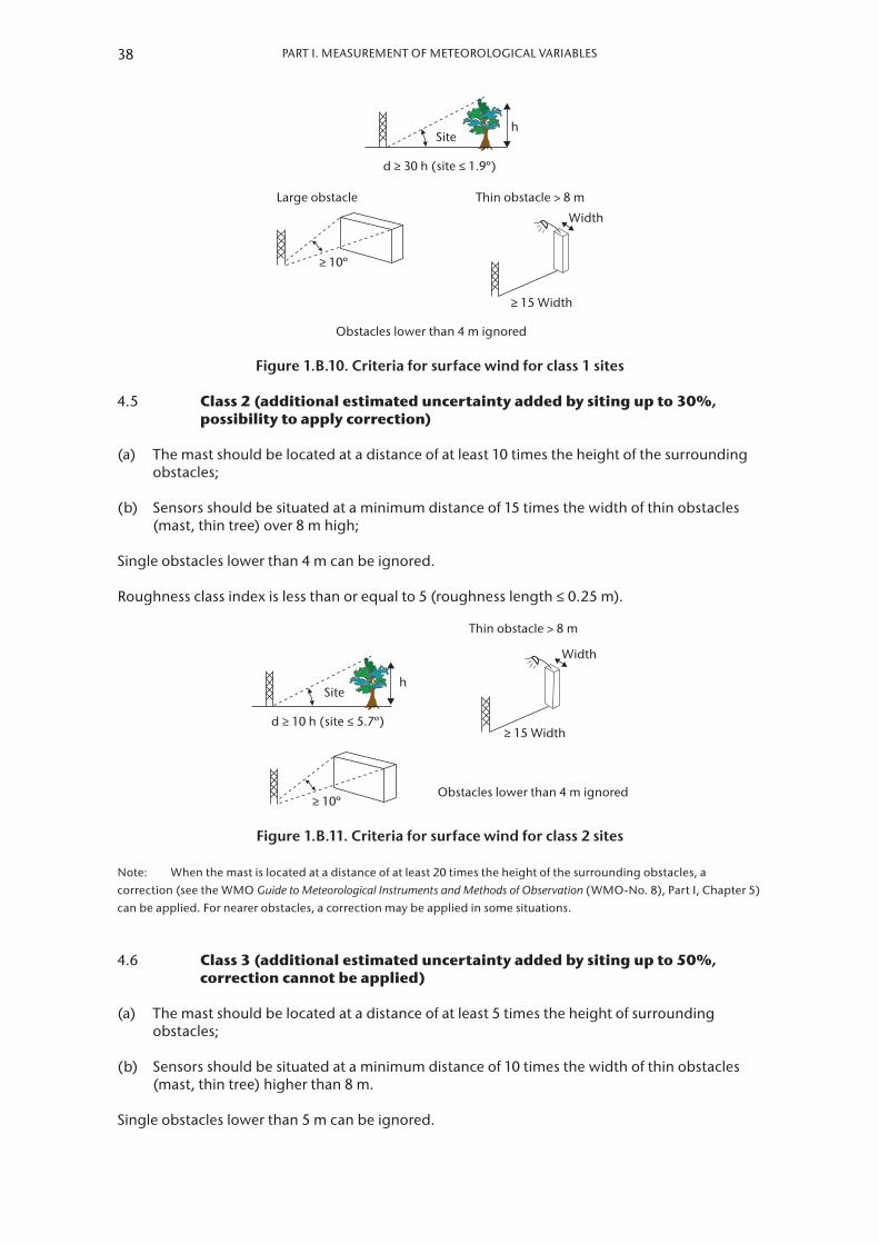
Figure 1.B.10. Criteria for surface wind for class 1 sites
4.5 Class 2 (additional estimated uncertainty added by siting up to 30%, possibility to apply correction)
(a) The mast should be located at a distance of at least 10 times the height of the surrounding obstacles;
(b) Sensors should be situated at a minimum distance of 15 times the width of thin obstacles (mast, thin tree) over 8 m high;
Single obstacles lower than 4 m can be ignored.
Roughness class index is less than or equal to 5 (roughness length ≤ 0.25 m).
h
Thin obstacle > 8 m
d ≥ 10 h (site ≤ 5.7º)
≥ 10º
≥ 15 Width
Width
Site
Obstacles lower than 4 m ignored
Figure 1.B.11. Criteria for surface wind for class 2 sites
Note: When the mast is located at a distance of at least 20 times the height of the surrounding obstacles, a correction (see the WMO Guide to Meteorological Instruments and Methods of Observation (WMO-No. 8), Part I, Chapter 5) can be applied. For nearer obstacles, a correction may be applied in some situations.
4.6 Class 3 (additional estimated uncertainty added by siting up to 50%, correction cannot be applied)
(a) The mast should be located at a distance of at least 5 times the height of surrounding obstacles;
(b) Sensors should be situated at a minimum distance of 10 times the width of thin obstacles (mast, thin tree) higher than 8 m.
Single obstacles lower than 5 m can be ignored.
38 PART I. MEASUREMENT OF METEOROLOGICAL VARIABLES

CHAPTER 1. GENERAL
h
d ≥ 5 h (site ≤ 11.3º)
> 8 m
≥ 10 Width
Width
Site Obstacles lower than 5 m ignored
Figure 1.B.12. Criteria for surface wind for class 3 sites
4.7 Class 4 (additional estimated uncertainty added by siting greater than 50%)
(a) The mast should be located at a distance of at least 2.5 times the height of surrounding obstacles;
(b) No obstacle with an angular width larger than 60° and a height greater than 10 m, within a 40 m distance.
Single obstacles lower than 6 m can be ignored, only for measurements at 10 m or above.
h
d ≥ 2.5 h (site ≤ 21.8º)
> 10 m
> 60º
40 m
No
Site
Obstacles lower than 6 m ignored
Figure 1.B.13. Criteria for surface wind for class 4 sites
4.8 Class 5 (additional estimated uncertainty cannot be defined)
Site not meeting the requirements of class 4.
5. GLOBAL AND DIFFUSE RADIATION
5.1 General
Close obstacles have to be avoided. Shading due to the natural relief is not taken into account for the classification. Non-reflecting obstacles below the visible horizon can be neglected.
An obstacle is considered as reflecting if its albedo is greater than 0.5.
The reference position for elevation angles is the sensitive element of the instrument.
5.2 Class 1
(a) No shade projected onto the sensor when the sun is at an angular height of over 5°. For regions with latitude ≥ 60°, this limit is decreased to 3°;
(b) No non-shading reflecting obstacles with an angular height above 5° and a total angular width above 10°.
39

JGODDPD LDODODODJFOSOKSOS SOSOS SOSOSOSOSOSOSOSSKDDFJSISOSOSK SLSL S SLSLSLSLSSLSLSLSLSLS KSKSKSKSKSKSKS K SKSKSK
JGODDPD LDODODODJFOSOKSOS SOSOS SOSOSOSOSOSOSOSSKDDFJSISOSOSK SLSL S SLSLSLSLSSLSLSLSLSLS KSKSKSKSKSKSKS K SKSKSK
No non-shading obstacles withtotal angular width > 10º
No shade
5º 5º
Figure 1.B.14. Criteria for global and diffuse radiation for class 1 sites
5.3 Class 2
(a) No shade projected onto the sensor when the sun is at an angular height of over 7°. For regions with latitude ≥ 60°, this limit is decreased to 5°;
(b) No non-shading reflecting obstacles with an angular height above 7° and a total angular width above 20°.
JGODDPD LDODODODJFOSOKSOS SOSOS SOSOSOSOSOSOSOSSKDDFJSISOSOSK SLSL S SLSLSLSLSSLSLSLSLSLS KSKSKSKSKSKSKS K SKSKSK
JGODDPD LDODODODJFOSOKSOS SOSOS SOSOSOSOSOSOSOSSKDDFJSISOSOSK SLSL S SLSLSLSLSSLSLSLSLSLS KSKSKSKSKSKSKS K SKSKSK
No non-shading obstacles withtotal angular width > 20º
7º 7º
Figure 1.B.15. Criteria for global and diffuse radiation for class 2 sites
5.4 Class 3
(a) No shade projected onto the sensor when the sun is at an angular height of over 10°. For regions with latitude ≥ 60°, this limit is decreased to 7°;
(b) No non-shading reflecting obstacles with an angular height above 15° and a total angular width above 45°.
JGODDPD LDODODODJFOSOKSOS SOSOS SOSOSOSOSOSOSOSS
KDDFJSISOSOSK SLSL S SLSLSLSLSSLSLSLSLSLS
KSKSKSKSKSKSKS K SKSKSK
JGODDPD LDODODODJFOSOKSOS SOSOS SOSOSOSOSOSOSOSS
KDDFJSISOSOSK SLSL S SLSLSLSLSSLSLSLSLSLS
KSKSKSKSKSKSKS K SKSKSK
No non-shading obstacles withtotal angular width > 45º
15º10º
Figure 1.B.16. Criteria for global and diffuse radiation for class 3 sites
5.5 Class 4
No shade projected during more than 30% of the daytime, for any day of the year.
JGODDPD LDODODODJFOSOKSOS SOSOS SOSOSOSOSOSOSOSSKDDFJSISOSOSK SLSL S SLSLSLSLSSLSLSLSLSLS KSKSKSKSKSKSKS K SKSKSK
No shade projected for more than 30% of daytime
≤ 30% of daytime
Figure 1.B.17. Criteria for global and diffuse radiation for class 4 sites
40 PART I. MEASUREMENT OF METEOROLOGICAL VARIABLES

CHAPTER 1. GENERAL
5.6 Class 5
Shade projected during more than 30% of the daytime, for at least one day of the year.
6. DIRECT RADIATION AND SUNSHINE DURATION
6.1 General
Close obstacles have to be avoided. Shading due to the natural relief is not taken into account for the classification. Obstacles below the visible horizon can be neglected.
The reference position for angles is the sensitive element of the instrument.
6.2 Class 1
No shade projected onto the sensor when the sun is at an angular height of over 3°.
3º
Figure 1.B.18. Criteria for direct radiation and sunshine duration for class 1 sites
6.3 Class 2
No shade projected onto the sensor when the sun is at an angular height of over 5°.
5º
Figure 1.B.19. Criteria for direct radiation and sunshine duration for class 2 sites
6.4 Class 3
No shade projected onto the sensor when the sun is at an angular height of over 7°.
7º
Figure 1.B.20. Criteria for direct radiation and sunshine duration for class 3 sites
41

6.5 Class 4
No shade projected during more than 30% of the daytime, for any day of the year.
No shade for more than 30% of daytime
≤ 30% of daytime
Figure 1.B.21. Criteria for direct radiation and sunshine duration for class 4 sites
6.6 Class 5
Shade projected during more than 30% of the daytime, for at least one day of the year.
42 PART I. MEASUREMENT OF METEOROLOGICAL VARIABLES