annals of faculty engineering hunedoara –...
TRANSCRIPT

ANNALS of Faculty Engineering Hunedoara – International Journal of Engineering
103 |Fascicule 2
Tome XIII [2015] – Fascicule 2 [May] ISSN: 1584-2665 [print]; ISSN: 1584-2673 [online] a free-access multidisciplinary publication of the Faculty of Engineering Hunedoara
1. Ibrahim PLANČIĆ, 2. Darko PETKOVIĆ, 3. Samir LEMEŠ, 4. Hazim BAŠIĆ
RESEARCH ON IMPACT FACTORS INFLUENCING ROUNDNESS OF PRODUCTS MADE OF AL 99.5% FORMED BY FLOW FORMING TECHNOLOGY
1-3. University of Zenica, Faculty of Mechanical Engineering, Zenica, BOSNIA & HERZEGOVINA
4. University of Sarajevo, Faculty of Mechanical Engineering in Sarajevo, BOSNIA & HERZEGOVINA
Abstract: Cold forming is characterized by a number of advantages which are mainly result of material strengthening during the final workpiece formation. Effects of material strengthening are reflected in shaping accuracy and in improving mechanical characteristics of workpieces. Flow forming is one of the specific forming methods used to form different parts of rotationally symmetrical parts in military, aeronautical, nuclear and other industries, which uses positive effects of the material strengthening. Design of products for extremely demanding industries, in addition to dimensional control, requires checking the accuracy of their circular shape. This paper, through the example of making tubular workpieces from Al 99.5% using flow forming technology, presents a method for determining the workpiece roundness using a 3D Coordinate Measuring Machine and analyzes the influence of number of revolutions, shift and the deformation rate to the deviation of roundness. Keywords: Al 99.5%, Forward Cold Flow Forming, Workpiece Roundness 1. INTRODUCTORY PART The cold metal flow forming as a specific method of a rotary shaping enables, in addition to shaping the pieces of different dimensions, reduction of thickness of wall. Due to the reduction of thickness in the cold state, an efect of strengthening of material happens, which improves the mechanical characteristics. In addition to enhancement of charactersitics of strength of manufactured parts, it is pretty significant that this method can be used to model parts of satisfactory accuracy of shape and dimension. The reason for this research is a lack of practical recommendation and experience regarding the efficient shaping of parts of Aluminium of pureness 99,5% (technically pure aluminium) by use of forward cold flow forming method. Therefore, to study the factors which impact the accuracy of shape and dimensions of workpieces manufactured on the basis of flow forming method, the experimental researches were conducted on the pieces of technically pure aluminium Al 99,5. 2. TECHNOLOGY OF FORWARD COLD FLOW FORMING The essence of cold flow forming (CFF) method as a rotary shaping method is to have the material, under the influence of pressure of rolls (two or three), transformed into the field of plastic flow and pushed in the axial direction while reducing the diameter and increasing the length of the workpiece. There are several methods of CFF tubular parts, and two main types of technology process of CFF are: forward or direct (FCFF) and indirect / in an opposite direction (ICFF). The variants mainly differ in the way the material flows considering the direction of moving the rolls, while the deformation of metals in both variants is localized to a narrow contact zone of contact tool-rolls and workpiece materials. Figure 1 is a schematic presentation of the principle of forming the subject variants HRIV with the working elements of tools. In a direct CFF (Figure 1, left) flow of non-deformed material of workpiece / a preformed shape, the movement of rolls (tools) is in the same direction, and in an indirect CFF, which is in opposit direction, (Figure 1, right) flow of material is also in the opposit direction in regard to the direction of movement of rolls. Since the purpose of this research primarly was to determin the possibility of using the FCFF techonology on Al 99,5 to make a workpiece of satisfactory accuracy of shape and dimension with the adequate strength, it is necessary, in addition to controlling the dimensions of workpiece, to check the precision of its geometry by measuring roundness on 3D coordinate measuring machine.
Figure 1. Scheme of procedure of direct (left) and oppositional (right) CFF [1]

ISSN: 1584-2665 [print]; ISSN: 1584-2673 [online]
104 | Fascicule 2
3. ROUNDNESS OF WORKPIECE AND WAYS TO MEASURE IT According to the definition, roundness refers to the state of circular line or surface of circular part, which all points on the line or on the circumference of the cross section are equidistant from a central point. Deviation from roundness is the radial width of the annular area between the two coplanar, mutually concentric circles. Since the 1950., when this term was introduced, the roundness was defined as an important characteristic of process, which enhanced the quality of defining the round-shaped parts. In the course of time, devices for measuring and control have been further developed. It is well known that today in specifications of equipment, needed for technical control and measurements in big, and also in small production organizations, due to many advantages, the coordinate measuring machines are the most applied. They execute many different measurements, but, also, provide possibility to measure roundness using the modern methods. These are methods of examining roundness with the external measuring reference (type of rotating tabel and type of rotating antenna), in contrary to the conventional method with the internal measuring reference (diametrical examining of roundness, examining of roundness by using the measuring spikes and examining of roundness by using the V-prism). For measuring roundness, as other devices, the coordinate measuring devices detect small deviations from an ideal shape of circle ("out of-round"), and today are used four recognizable methods to assess deviations from roundness: Method of the smalles circular squares, Method of the smalles circular zone, Method of the smallest circumscribed circle and Method of the biggest inscribed circle. Results of measuring roundness by these methods in average differentiate 10-15% [4]. 4. EXPERIMENTAL WORK In order to determin accuracy of manufacturing the parts of technically pure Aluminum in the course of cold forming, shaping Al 99,5 chamber was done in two phases of FCFF technology. Figure 2 brings dimensions of preform and workpiece by phases of FCFF technology.
Preform
Workpiece after the 1st phase
Workpiece after the 2nd phase
Figure 2. Desing and dimension of preform and workpiece in the 1st and 2nd phase of FCFF technology 4.1. Plan of experiment For the experimental research, a total factor plan of experiment with three independent changeable factors (k=3) was used, and the experiment was repeated in the central point of the plan (zero plan point). Matrix plan and levels of variation of factors in the first and in the second phase are presented in the table of research results, Table 1.
Tabel 1. Comparative data on measuring roundness after the 1st and 2nd phase of FCFF technology
Run
Plan-matrix and natural factors levels in: ∅Α [mm]
ϕƩ
[%]
Parameters of roundness of workpieces after: I-first stage II-second stage I-first stage II-second stage
n [º/min]
sv
[mm/º] ∆s [mm] n [º/min] sv
[mm/º] ∆s [mm] Roundness [µm]
No. of Point
Roundness [µm]
No. of Point
0 Preform 109,6 0,02577 1036 - - 1 140 60 2 140 60 3,5 98,8 53,5 0,10912 998 0,16080 1836 2 240 60 2 240 60 3,5 98,8 53,4 0,17314 998 0,24337 1837 3 140 100 2 140 100 3,5 99,0 52,3 0,15110 1004 0,28626 1840 4 240 100 2 240 100 3,5 98,7 57,6 0,19841 999 0,15883 1836 5 140 60 3,5 140 60 2 99,0 51,7 0,20961 967 0,12755 1843 6 240 60 3,5 240 60 2 99,0 51,6 0,35027 966 0,12252 1840 7 140 100 3,5 140 100 2 99,2 50,7 0,20391 971 0,05995 1843 8 240 100 3,5 240 100 2 99,0 52,0 0,25744 969 0,06742 1847 9 190 80 2,75 190 80 2,75 - 0,14998 988 - -
10 190 80 2,75 190 80 2,75 98,5 55,2 0,13363 988 0,08723 1842 11 190 80 2,75 190 80 2,75 98,8 53,2 0,10681 988 0,18138 1834 12 190 80 2,75 140 60 3,5 99,0 52,2 0,09001 984 0,18004 1836
where is: Rpm mandrel n [º/min]; Feed sv [mm/º]; Depth of forming ∆s [mm]; ∅Α Final outer diameter workpieces [mm] On the basis of the experiment plan, there were 12 samples made by cold plastic forming by the FCFF procedure in two phases. The achieved total degree of deformation during shaping is in the range from 50,7 to 57,6 %, and the partial degrees of deformation in specific phases are in the range of ϕI=15,3 do 35,4 % and ϕII=16,3 do 37 %.
ANNALS of Faculty Engineering Hunedoara– International Journal of Engineering
105 | Fascicule 2
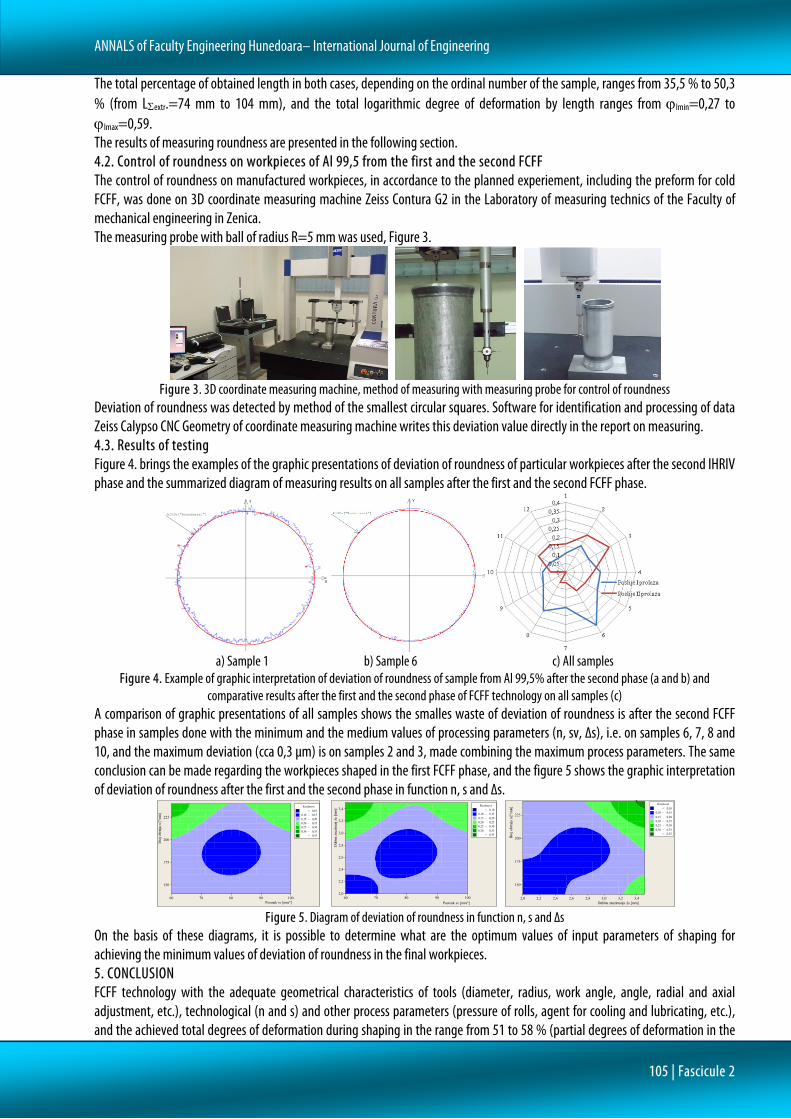
The total percentage of obtained length in both cases, depending on the ordinal number of the sample, ranges from 35,5 % to 50,3 % (from LΣextr.=74 mm to 104 mm), and the total logarithmic degree of deformation by length ranges from ϕlmin=0,27 to ϕlmax=0,59. The results of measuring roundness are presented in the following section. 4.2. Control of roundness on workpieces of Al 99,5 from the first and the second FCFF The control of roundness on manufactured workpieces, in accordance to the planned experiement, including the preform for cold FCFF, was done on 3D coordinate measuring machine Zeiss Contura G2 in the Laboratory of measuring technics of the Faculty of mechanical engineering in Zenica. The measuring probe with ball of radius R=5 mm was used, Figure 3.
Figure 3. 3D coordinate measuring machine, method of measuring with measuring probe for control of roundness
Deviation of roundness was detected by method of the smallest circular squares. Software for identification and processing of data Zeiss Calypso CNC Geometry of coordinate measuring machine writes this deviation value directly in the report on measuring. 4.3. Results of testing Figure 4. brings the examples of the graphic presentations of deviation of roundness of particular workpieces after the second IHRIV phase and the summarized diagram of measuring results on all samples after the first and the second FCFF phase.
a) Sample 1 b) Sample 6 c) All samples
Figure 4. Example of graphic interpretation of deviation of roundness of sample from Al 99,5% after the second phase (a and b) and comparative results after the first and the second phase of FCFF technology on all samples (c)
A comparison of graphic presentations of all samples shows the smalles waste of deviation of roundness is after the second FCFF phase in samples done with the minimum and the medium values of processing parameters (n, sv, ∆s), i.e. on samples 6, 7, 8 and 10, and the maximum deviation (cca 0,3 µm) is on samples 2 and 3, made combining the maximum process parameters. The same conclusion can be made regarding the workpieces shaped in the first FCFF phase, and the figure 5 shows the graphic interpretation of deviation of roundness after the first and the second phase in function n, s and ∆s.
Figure 5. Diagram of deviation of roundness in function n, s and ∆s
On the basis of these diagrams, it is possible to determine what are the optimum values of input parameters of shaping for achieving the minimum values of deviation of roundness in the final workpieces. 5. CONCLUSION FCFF technology with the adequate geometrical characteristics of tools (diameter, radius, work angle, angle, radial and axial adjustment, etc.), technological (n and s) and other process parameters (pressure of rolls, agent for cooling and lubricating, etc.), and the achieved total degrees of deformation during shaping in the range from 51 to 58 % (partial degrees of deformation in the
Posmak sv [mm/º]
Broj
obr
taja
n [º
/min]
10090807060
225
200
175
150
> – – – – – < 0,10
0,10 0,150,15 0,200,20 0,250,25 0,300,30 0,35
0,35
Kružnost
Posmak sv [mm/º]
Dub
ina za
uzim
anj ∆
s [m
m]
10090807060
3,4
3,2
3,0
2,8
2,6
2,4
2,2
2,0
> – – – – – < 0,10
0,10 0,150,15 0,200,20 0,250,25 0,300,30 0,35
0,35
Kružnost
Dubina zauzimanja ∆s [mm]
Broj
obr
taja
n [º
/min]
3,43,23,02,82,62,42,22,0
225
200
175
150
> – – – – – < 0,10
0,10 0,150,15 0,200,20 0,250,25 0,300,30 0,35
0,35
Kružnost

ISSN: 1584-2665 [print]; ISSN: 1584-2673 [online]
106 | Fascicule 2
particular phases in the range from ϕI=15 to 35 % and ϕII=16 to 37 %) efficiently can shape the axisymmetric workpieces of satisfactory accuracy of shape and dimension and with the improved strength characteristics comparing to the material of preform. On the presented diagrams, it can be seen that the smallest value of deviation of roundness for shaping Al 99,5 by FCFF procedure is in workpieces shaped by the medium values of the number of revolutions per minute (rpm) (170-200 r/min), feed rate (70-90 mm/o) and depth of forming-tool positioning (2-3 mm). Data on deviation of roundness after the second phase of FCFF technology indicated that they were lower than in subject workpieces after the first phase. During both phases, depth tool positioning of rolls, had a little bit bigger impact on the roundness. If its value increases, deviation of roundness increases too. Therefore, to have more precise circular shapes of tubular workpieces, smaller degrees of depth of forming of rolls in shaping should be choosen. The conducted regression analysis shows that a mathematical model of dependence of roundness on n, s and depth of tool positioning (∆s), i.e. the degree of deformation, can not be made with the sufficient reliability. The comparison of the obtained data on measuring deviation of roundness of workpieces after the first and the second phase of FCFF technology leads to the conclusion that the mentioned procedure of processing (shaping) rotationally symetrical workpieces of Al 99,5 can safely produce parts with the maximum deviation from an ideal circular shape in the range from 0,2 to 0,4 µm. References [1.] Ekinović S., Plančić I., Begović E., Đukić H., Muminović B. (2014)., Material strengthening in forming final tubular product
from Al 99.5 % by forward cold flow forming, X NSS ''Metalni i nemetalni materijali'' Bugojno, B&H, 21-22. april 2014. [2.] Nikačević M., Radović Lj. (2010). Rotaciono valjanje: specifična tehnologija za izradu delova raketa, kumulativna
naučnotehnička informacija, Vojnotehnički institut Beograd, Naučno tehničke informacije, ISSN 1820-3418, Vol. XLIV No. 2. [3.] Šotra V., Raković A. (2008). Merenje tolerancija oblika i položaja delova kružnog oblika, Tehnička dijagnostika (1), 19-24,
UDC: 62-422.11-777:629.05, Beograd. [4.] Nugent P. (2008). Form Measurement Fundamentals, Metrology center Mahr. [5.] Pavelić V. (1995). Specifične tehnologije u proizvodnji oružja, Novi Travnik-Zagreb, MORH-TP-4/95.
ANNALS of Faculty Engineering Hunedoara – International Journal of Engineering
copyright © UNIVERSITY POLITEHNICA TIMISOARA, FACULTY OF ENGINEERING HUNEDOARA,
5, REVOLUTIEI, 331128, HUNEDOARA, ROMANIA http://annals.fih.upt.ro