annals of daaam for 2012 & proceedings of the 23rd...
TRANSCRIPT
Annals of DAAAM for 2012 & Proceedings of the 23rd International DAAAM Symposium, Volume 23, No.1, ISSN 2304-1382
ISBN 978-3-901509-91-9, CDROM version, Ed. B. Katalinic, Published by DAAAM International, Vienna, Austria, EU, 2012
Make Harmony between Technology and Nature, and Your Mind will Fly Free as a Bird
Annals & Proceedings of DAAAM International 2012
THE CHOICE OF PARAMETERS FOR WELDING OF STEEL S355NL
KOLARIK, L[adislav]; KOLARIKOVA, M[arie]; VONDROUS, P[etr] & HRABINA, R[udolf]
Abstract: Research work is focused on welding of fine grained nomalised steel S355NL with high thickness 50 mm for crane construction. Double sided V-groove butt weld done by GMAW with filler OK Autrod 12.60. Welding parameters and cycle were designed according to norm EN 1011-2. Carbon equivalent, parameter U.C.S. served to set preheat and interpass temperature. No weld heat treatment was used. Destructive and non-destructive testing served to certify used welding process. Keywords: S355NL, GMAW, NDT, Hot Cracking, Preheat Temperature
1. INTRODUCTION
Normalised construction steels are often used for dynamically stressed welded constructions as bridges, cranes etc. For such applications according to norms, welds need to have high strength and notch toughness. Especially for high thickness plates welding heat cycle (welding parameters, pre, post heating) influence very much these strength values and breaking from optimaly designed values leads to unacceptable welding results.
2. BASE MATERIAL AND ITS PROPERTIES
Base material is S355NL, micro alloyed fine grained
steel. Fine grain normalized structure normalizing (N suffix) is obtained by rolling at controlled temperatures (end of rooling finishes at Ar3+50°C). According to EN 10028-5 normalised steels are produced upto yield strength 460 MPa for use in low (suffix L) or high temperature environments (suffix H). Low temperature variant steel is useful for fatigue stressed applications. These steels are also very good for welded constructions.[1]
The most widely used steel S355NL was selected. Chemical composition and mechanical properties are at Tab. 1 and at Tab. 2. Special is that notch toughness at –50°C needs to be min. 37 J.
C [%] Si
[%] Mn[%] P [%] S [%] Nb[%] V [%].
<0.018 <
0.50
0.90 -
1.65
<
0.03 <0.025 < 0.05 < 0.12
Al [%] Ti
[%] Cr [%]
Ni [%]
Mo[%] Cu [%]
N [%]
< 0.02 <
0.03 < 0.30
<
0.50 < 0.10 < 0.35 <0.015
Tab. 1. Steel S355NL chemical composition [11]
Rm [MPa] + 20°C
Re [MPa] + 20°C
A5 [%] + 20°C
KV [J] - 40°C
470 - 630 >315 ~ 22 endways : 34
across : 20
Tab. 2. Mechanical properties of S355NL [11]
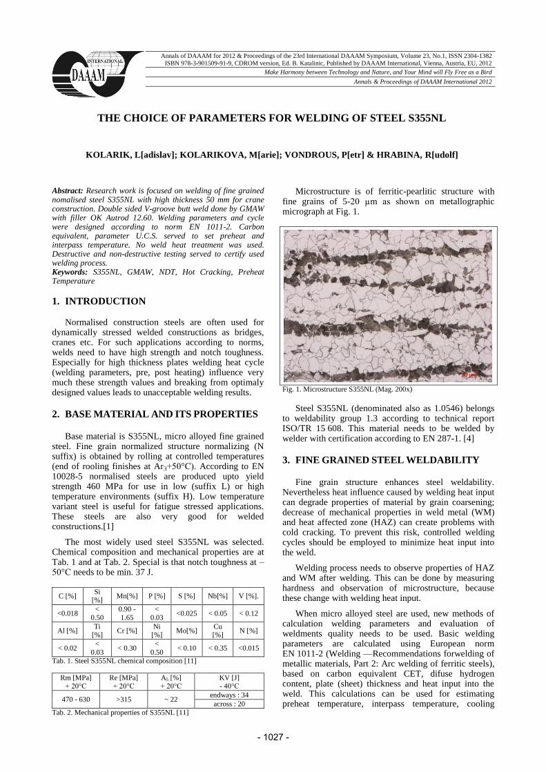
Microstructure is of ferritic-pearlitic structure with fine grains of 5-20 µm as shown on metallographic micrograph at Fig. 1.
Fig. 1. Microstructure S355NL (Mag. 200x) Steel S355NL (denominated also as 1.0546) belongs
to weldability group 1.3 according to technical report ISO/TR 15 608. This material needs to be welded by welder with certification according to EN 287-1. [4]
3. FINE GRAINED STEEL WELDABILITY
Fine grain structure enhances steel weldability.
Nevertheless heat influence caused by welding heat input can degrade properties of material by grain coarsening; decrease of mechanical properties in weld metal (WM) and heat affected zone (HAZ) can create problems with cold cracking. To prevent this risk, controlled welding cycles should be employed to minimize heat input into the weld.
Welding process needs to observe properties of HAZ and WM after welding. This can be done by measuring hardness and observation of microstructure, because these change with welding heat input.
When micro alloyed steel are used, new methods of calculation welding parameters and evaluation of weldments quality needs to be used. Basic welding parameters are calculated using European norm EN 1011-2 (Welding —Recommendations forwelding of metallic materials, Part 2: Arc welding of ferritic steels), based on carbon equivalent CET, difuse hydrogen content, plate (sheet) thickness and heat input into the weld. This calculations can be used for estimating preheat temperature, interpass temperature, cooling
- 1027 -
speed, time t8/5 to reach necessary toughness and hardness.
4. EXPERIMENTAL
Firstly carbon equivalent CET was calculated; preheat temperature Tp, cracking sensitivity parameter U.C.S. and critical cooling time t8/5. On base of these calculations welding parameters were selected and used for welding. After welding, quality was assessed by non-destructive and destructive methods, especially visual testing, penetration and X-ray testing, micrographic evaluation and hardness measurement.
5. WELDING PARAMETERS
Sample of thickness 50 mm was beveled to create double sided V-beveled joint according to Fig. 2.
Fig 2 – Joint faces preparation for 50 mm thick sample accordint o EN ISO 9692-1
Root opening was between plates a = 2 - 4 mm,
groove angle α = 55° - 75° and depth of root face b = 0 - 4 mm.
Carbon equivalent calculation: Calculation of CET is basic parameter used for
evaluating weldability for steels. For CET calculation equation from EN 1011 was used:
302.0402010
NiCuCrMoMnCCET (1)
For thickness 50 mm the CET parameters to assure
that cold cracks would not form should be CETmax = 0.22. For our case 0.302 > 0.22, so special measures should be taken, i.e. preheating, postheating. The easiest is preheating, so we selected preheating. [3]
Preheating calculation: Very many empirical calculations for preheat
temperature can be used. Usually these calculations should be used for materials of certain chemical composition. For our steel, Sefarian equation was used. [2]:
25,0.350 pp CT (2)
where:
scp CCC (3)
360
2820)(40360 MoNiCrMnCCc
(4)
cs CsC ..005,0 (5)
Where s is sample thickness.
Preheat temperature was calculaded to be:
Tp = 133, 9°C.
According to experience preheat temperature was selected bit higher than as calculated, thus Tp = 150°C (see Fig. 8).
Hot cracking sensitivity: For estimating hot cracking sensitivity U.C.S.,
parametric equation as in EN 1011 was used for calculation:
(6)
Usually parameter U.C.S. should be below 30 to
assure no risk of hot cracking caused by multilayer welding. As calculated U.C.S. is higher (61.75 > 30) precautions should be taken to limit heat input into the weld. Special precautions to keep the limited heat input, interpass temperature Ti=180°C, pulled welds without weave, turn over the weldment in each layer etc.
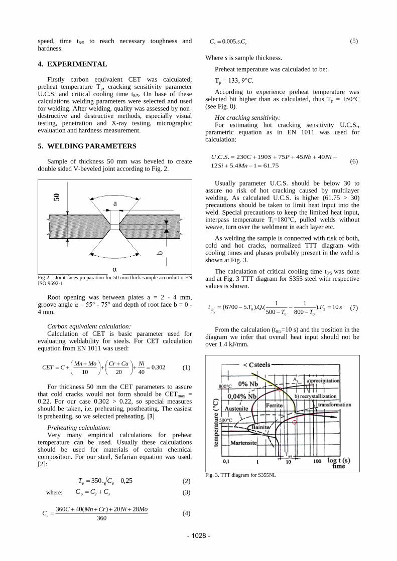
As welding the sample is connected with risk of both, cold and hot cracks, normalized TTT diagram with cooling times and phases probably present in the weld is shown at Fig. 3.
The calculation of critical cooling time t8/5 was done and at Fig. 3 TTT diagram for S355 steel with respective values is shown.
(7)
From the calculation (t8/5=10 s) and the position in the
diagram we infer that overall heat input should not be over 1.4 kJ/mm.
Fig. 3. TTT diagram for S355NL
a
50
α
b
sFTT
QTt 10).800
1
500
1.()..56700( 3
00
05
8
75.6114.512
404575190230...
MnSi
NiNbPSCSCU
- 1028 -

6. PRACTICAL TEST DESIGNED WELDING
PARAMETERS
Used welding source is ESAB Origo MIG 5004i with
filler ESAB OK Aristorod 12.60 (EN ISO 14341-A: G3Si1). Shielding gas is active gas, mixture 92/18 of Ar+CO2 and flow 15 l/min.
Chemical composition of filler wire and estimated WM properites are at Tab. 3, Tab. 4 as they are published by the wire manufacturer.
For welding root layer current 145 A and voltage 20 V were used with welding speed 2.3 mm/s. For filling and caping layers increased parametres were used: I = 220 A, U = 27,5 V and speed v = 6 mm/s.
Heat input calucaltion (acc. to EN 1011):
v
IUQ
.1000
.. [kJ/mm] (8)
Effectivity parameter (η) for GMAW is 0,8. As calculated, heat input for root layer is Q1 = 0.99 kJ/mm and for filling layers Q2 = 0.8 kJ/mm.
Fig. 4 – Used welding source – ESAB Origo MIG 5004i
C Mn Si P S Cr Ni
0.081 1.44 0.86 0.014 0.011 0.03 0.03
Mo V Cu Al Fe Zr+Ti
0.005 0.002 0.04 0.002 rest 0.006
Tab 3. Chemical composition (wt. %) of wire OK Aristorod 12.60
Temperature
[°C]
Re H
[MPa]
Rm
[MPa]
A5
[%]
Notch
toughness
[J]
+20 470 560 26 130
-20 - - - 90
-30 - - - 70
-40 - - - 60
Tab. 4. Weld metal properites using filler wire OK Aristorod 12.60
7. RESULTS
Weld testing after welding by NDT visual testing, by penetration testing and by X-ray testing did pass all the
necessary tests. No unacceptable welding defects were found.
On metallographic macro and micrographs, the structure was observed and hardness was measured.
Macrostrcture is shown at Fig. 5. HAZ size is small; its width is approx. 2.5 mm, which is quite little, thanks to special precautions during welding. The 60 weld beads in multiple layers are well visible.
Fig. 5 – Macrostrucutral sample of weldment
At Fig. 6 and 7 are shown micrographs of WM and HAZ.
As is visible on comparison of BM and WM, Fig. 1+6, the WM grains did substantialy grow and have dendritic character typical for fused metal. The grains are of ferritic-pearlitic composition with almost pure ferrit at the grain boundaries.
Fig. 6 – WM microstructure (Mag. 200x)
- 1029 -

Fig. 7 – HAZ microstructure (Mag. 200x)
Compared to WM, which has rather big grains, in HAZ, there was observed grain refining because of welding process. The size of grains is small in range of 1-5 µm.
HV10 Average
HV10
Indent
placement Notes
148
150 BM
Caping layer
1
149
154
182
217 HAZ 211
259
206
201 WM 194
204
242
208 HAZ 203
178
162
154 BM 150
150
151
156 BM
Root layer
155
161
188
206 HAZ 201
228
219
215 WM 215
212
228
207 HAZ 198
196
162
155 BM 152
151
151
152 BM
Caping layer
2
151
155
174
223 HAZ 234
261
209
197 WM 176
207
247
236 HAZ 261
200
159
154 BM 153
151
Tab. 5 – Results of hardness measurement
Hardness testing was done according to ČSN EN ISO 6507-1 and ČSN EN ISO 9015-1. Hardness was measured from BM across HAZ, WM and till reach other side of BM.
For thickness 50 mm measurement was done in 3 layers – in the middle, and in each caping layer (2 mm under each surface).
For this material, usually critical hardness is set up to 450 HV10 and WM, HAZ hardness should not cross this limit. This limit was complied for all measured points. Hardness and its evolution are as would be expected for good weld in this material. In caping layers, maximum hardness is in HAZ and in root layer maximum hardness is in WM.
Fig. 8 – Interpass temperature measuring
Mechanical tests containing notch toughness and tensile strength were done as well, but are not presented in this article.
8. CONCLUSION
It was proved by results of NDT and DT testing that for successful welding of fine grained normalized steel of higher thicknesses, specified thermal welding cycle should be used. The norm EN 1011 can be well used for calculation of preheat temperature, interpass temperature etc. Welding of double sided V groove-beveled joint of 50 mm thick S355NL did in all testing proved satisfactory resuls according to all applied standards.
9. ACKNOWLEDGEMENT
The research was financed by the Czech Ministry of Education, Youth and Sport within the frame of project SGS CVUT 2010 – OHK2-038/10.
10. REFERENCES [1] Pilous, V.(2011). Welding of Fine-Grained Steels S355 N in
Protective Gases Using the Wires OK AristoRod 12, Konstrukce, 12/ 2011, ISSN 1803-8433
[2] Seferián, D. (1959). Métallurgie de la Soudure, Dunod, Paris
[3] Pilous, V. (2012). Heat Treatment of Welded Structures of Common Carbon Structural Steel S235 and High-Strength Low-Alloy Structural Steel S355 in Accordance With ISO 17663, Konstrukce 05, 2012, ISSN 1803-8433
[4] Janovec, J., Pilous, V. (2011). Using the Normalized Heat-Treated Steels S355NL and Thermo-Mechanically Treated S355ML, Konstrukce,11/2011, ISSN 1803-8433
- 1030 -