anil neerukonda institute of technology and … civil engineering news...civil engineering news,...
TRANSCRIPT

Civil Engineering News, Vol.4, No.1, September 2018, Department of Civil Engineering, ANITS 1
Anil Neerukonda Institute of Technology and Sciences
Newsletter published by Department of Civil Engineering
Vol.4 No. 1 September 2018
Patrons From the Chief Editor’s Desk
Dr.N.B.R.Prasad
Chairman
Dr.T.Subramanyam
Principal
Dr.T.V.Hanumantha Rao
Dean, Academic Affairs
I am delighted at the release of the this Issue of Civil Engineering News,
News letter published by Department of Civil Engineering, ANITS on the
eve of 51st Engineers Day, the 15th September, 2018, commemorating the
157th Birth Anniversary of the Engineering Wizard, Bharath Ratna Sir
Mokshagundam Visvesvaraya.
News letter acts as a communication channel in networking among the
faculty, students, alumni, Civil Engineering professionals in the Industry and Higher Learning
Institutions.
This issue contains 30 technical articles, 2 general articles apart from Department news such
as Department Profile, Professional Society Activities, Faculty Publications, Workshops/
Seminars / Symposia organized, R&D and Consultancy Projects in the Department, Faculty
Achievements, Seminars/ Workshops/ Conferences attended by Faculty and Student
Achievements for the year 2017-18.
I congratulate the faculty members as well as students for contribution of technical articles for
this issue on wide range of topics related to Civil Engineering. I also congratulate the
Editorial Board on this occasion.
I thank the following Civil Engineers for the contribution of technical articles for this issue
(1) Sri. M T Raju, Chief Engineer (Retd.), Polavaram Irrigation Project, North Coastal
districts, Visakhapatnam on “Polavaram Irrigation Project-The complete status report
as on August 2018”,
(2) Dr.-Ing. B.V.S. Viswanadham, Institute Chair Professor & Professor, Geotechnical
Engineering, Department of Civil Engineering, IIT Bombay on “Infrastructure
Geotechnics”
(3) Sri P. Bhagat Singh, Chief Engineer, Central Public Works Department (CPWD),
Trivendrum, on “Critical Decision Making through Calculated Risk – An Experience at
Port Blair”
(4) Sri Madan Kumar Annam, Head of Engineering, Keller India, Chennai on the topic
“Significance of Soil Investigation in Civil Engineering Industry”
I am sure that this issue of the News letter fulfilled its intended objective of enhancing the
technical knowledge and providing exposure to students to the latest developments in Civil
Engineering field.
We are grateful to the Management, Principal and Dean, Academic Affairs for their
continuous inspiration, encouragement, and support extended for the release of this “Civil
Engineering News” ~ Dr.B.N.D.Narasinga Rao
CCCooouuurrrssseeesss OOOffffffeeerrreeeddd
The Department of Civil Engineering, ANITS, offers the following AICTE approved courses:
B.Tech. (Civil Engineering) - 4 Years duration
M.Tech. (Civil Engineering) with Soil Mechanics specialization - 2 Years duration
Civil Engineering News

Civil Engineering News, Vol.4, No.1, September 2018, Department of Civil Engineering, ANITS 2
CCCOOONNNTTTEEENNNTTTSSS
Article Page
1) From the Editor’s Desk 1
2) Courses Offered 1
3) Department Profile 3
4) Professional Society Activities 5
5) Faculty Publications (2017-18) 6
6) Polavaram Irrigation Project – Complete Status Report – M T Raju, Chief Engineer (Retd.), Polavaram
Irrigation Project, North Coastal districts, Visakhapatnam
7
7) Workshops/ Seminars / Symposia organized (2017-18) 15
8) Infrastructure Geotechnics –Dr.-Ing. B.V.S. Viswanadham, Institute Chair Professor, Geotechnical
Engineering, Department of Civil Engineering, IIT Bombay
17
9) Critical Decision Making through Calculated Risk – An Experience at Port Blair –P. Bhagat Singh,
Chief Engineer, Central Public Works Department (CPWD), Trivendrum
18
10) R&D and Consultancy Projects in the Department 19
11) Significance of Soil Investigation in Civil Engineering Industry –Madan Kumar Annam,
Head of Engineering, Keller India, Chennai
20
12) Smart Cities: STAR Community Rating System, Dr, B.N.D.Narasinga Rao, Professor & Head 24
13) Faculty Achievements (2017-18) 28
14) Body – The Greatest Gadget: Sadguru –Dr. B N D NarasingaRao, Professor& Head 29
15) Non-Destructive Testing Of Concrete –J Vikranth, Associate Professor 30
16) Seminars/ Workshops/ Conferences Attended by Faculty 31
17) Pre-Engineered Building –Mr. M K S S K Chaitanya, Assistant Professor 32
18) Innovations in transportation engineering –T. Kiran Kumar, Assistant Professor 34
19) Ground Improvement Techniques For Curbing Liquefaction Related Problems –Ch. Vineel, Assistant
Professor
35
20) Gabion – Properties, Types, Applications & Advantages –T V ViswaTeja, Assistant Professor 37
21) Building Integrated Photovoltaics (BIPV) –P.Vandana Rao, Assistant Professor 40
22) Acoustic Doppler Velocimeter –M.Premchand, Assistant Professor 41
23) Green Buildings –Ch.Srinivas, Assistant Professor 43
24) Air - Heavy to Breath –J. Harsha vardhanareddy, Assistant professor 44
25) Eco-Friendly Non-Plastic Disposables –M. Nagalakshmi, Assistant Professor 46
26) Nonlinear Dynamic Analysis - The Only Option For Irregular Structures –P V R K Reddy, Assistant
Professor
47
27) SWOT/SWOC Analysis for Students –Mr. T V ViswaTeja, Assistant Professor 48
28) Student Achievements (2017-18) 50
29) Applications of Internet of Things (IOT) in Civil Engineering Constructions –K Swaroop, III Year, B
Tech Civil
51
30) Construction materials from waste –M. UshaRani, IV Year, B Tech Civil 52
31) Solar Trapping Tree –A Vaghna, IV Year B Tech Civil 53
32) Urban Municipal Waste Management –Ch. Rahul Reddy, S. Shanmukha Rao, IV Year B Tech Civil 54
33) The Jeddah Tower –G Raj Kumar, IV Year B Tech Civil 56
34) Eco-BLAC Brick (Pollution Free Bricks) –G Gouri Prasad, IV Year B Tech Civil 57
35) Why Can’t We Reuse? –Silaparasetti Jagadeesh Prasad, IV B Tech Civil 58
36) Brooklyn Bridge –Omkar Ganti, IV Year B Tech Civil 59
37) Precast Concrete Panels for Road Repairs –B. Gnanasagar, Ch.Ganesh, N. Mounika, T. Gayatri, P.
Madhukumar, IV Year B Tech Civil
60
38) Durability of concrete with partial replacement of cement by GGBS –N.SaiTeja, T.Sankeerthana,
P.Durga Rao, P.Gnana Prakash, T.Satyavathi, IV Year B Tech Civil
61
39) The Future of Transportation Engineering –R L N Harish, IV Year B Tech Civil 62
40) Soil Nailing –Ch.Soundarya, IV Year B Tech Civil 63
41) Prefabricated Vertical Drains (PVD) –Ch. Raghu Ram, Ch. Satya Srinivasa Rao, IV Year B Tech Civil 64
42) 100 Percent Fly ash Concrete – N. Yesupadam and M. Yaswant Krishna, IV Year B.Tech. Civil 65
43) Board of Studies & Editorial Board 66

Civil Engineering News, Vol.4, No.1, September 2018, Department of Civil Engineering, ANITS 3
DDDeeepppaaarrrtttmmmeeennnttt PPPrrrooofffiii llleee
ANITS
Anil Neerukunda Institute of Technology & Sciences
(ANITS) was founded by Anil Neerukunda Educational
Society (ANES), in the fond memory of Anil Neerukonda,
son of its chairman Dr. B.R.Prasad, Neerukonda. The
Institute’s humble journey started in 2001 with four
B.Tech. Programmes. Within 14 years of its establishment,
the Institute registered phenomenal growth and is
accredited by NAAC with A grade and by NBA twice. It is
permanently affiliated to Andhra University and achieved
Autonomous status by UGC in 2015.
Vision
ANITS envisions to emerge as a world-class technical institution
whose products represent a good blend of technological excellence
and the best of human values.
Mission
To train young men and women into competent and confident
engineers with excellent communicational skills, to face the
challenges of future technology changes, by imparting holistic
technical education using the best of infrastructure, outstanding
technical and teaching expertise and an exemplary work culture,
besides moulding them into good citizens.
Department of Civil Engineering
The Department of Civil Engineering, established in 2011,
offers the following programs
B.Tech. Civil Engineering
M.Tech. Soil Mechanics
Both programs are approved by AICTE and affiliated to
Andhra University.
Vision
Our Vision is to be among the preeminent Civil Engineering
Departments of the Country and the World for building future
Civil Engineers characterized by technological excellence and
human values.
Mission
Our Mission is Education. We achieve this mission through
teaching, research, and consultancy in Civil Engineering with
creativity, quality, sustainability, service and values as the
foundational hall marks.
Infrastructure
All laboratories in the department are well established with
latest and modern equipment. The Department has
Computer Centre, A/c Seminar hall, Department library
etc. The Department also has Arc GIS, STAAD Pro and 25
other civil engineering licensed software.
Triaxial Compression
Test equipment Compression Testing
equipment Los Angeles Abrasion
testing machine Total Station
Consolidation equipment Laboratory Concrete
Mixer Relative density
equipment Infra-red Moisture meter

Civil Engineering News, Vol.4, No.1, September 2018, Department of Civil Engineering, ANITS 4
DDDeeepppaaarrrtttmmmeeennnttt PPPrrrooofffiii llleee
Faculty
The Department is headed by Dr. B.N.D. Narasinga Rao,
having 25 years of Teaching, Research and Consultancy
experience. The Department is supported by qualified and
experienced faculty, including Prof. A.Ramamohana Rao,
and Dr.V.Venkateswara Rao, former Professors of Andhra
University as well as skilled technicians and non-teaching
staff. The Department has well equipped laboratories and
spacious classrooms.
He is also the Principal Investigator for UGC Minor
Research Project on Fly ash utilization. Dr. B.N.D.
Narasinga Rao, Professor & Head, Civil authored Text
Book on Soil Mechanics and Foundation Engineering,
Wiley International Publishers. This book is prescribed by
10 universities and Autonomous colleges across AP,
Tamilnadu, Odisha, Rajasthan and UP. Also the book was
cited as the Best Book in Soil Mechanics for GATE2017,
by the Websites ‘Entrances of India’ and ‘Indiatown.in’.
Text Book on Soil Mechanics, Wiley Publications, being
released by Prof. M.R.Madhav Visiting Professor, IIT,
Hyderabad
Centre for Industrial Consultancy and Sponsored
Research (ICSR)
The Centre for Industrial Consultancy and Sponsored
Research (ICSR) was established at ANITS to be an
effective Interface with the Industry in fostering
technology development, technical consultancy,
collaborative R&D for mutual benefits. The key agenda of
the IC&SR is to showcase and transfer the Institute’s
intellectual ware to industry and also inject industrial
relevance in teaching and research at ANITS. The
uniqueness lies in the wealth of expertise and modern
facilities of the Department, manned by qualified teaching
faculty with wide-ranging areas of specialization.
The Head of the Department Dr. Narasinga Rao is actively
involved in consultancy in Geotechnical engineering since
1993. He was the Principal Investigator for Geotechnical
Investigations worth more than Rs.10 lacs conducted
during 2017-18 for the 15 MW GVMC-Jindal
Collaborative Waste-to-Energy Power plant at
Kapuluppada
Consultancy Services
Geotechnical Engineering
Geotechnical Investigations and Reports
In-situ and laboratory testing of soil and rock
Soil & Rock Sample collection & Lab Testing
Recommendation of suitable foundation and
Solutions to Foundation problems
Structural Engineering
Design of Structures
Tests on cement, concrete, steel
Concrete Mix design
Tests on aggregates, bricks, stones
Tests on other building materials
Transportation Engineering Highway materials testing
Pavement design and maintenance
Traffic and Transportation Planning
Environmental Engineering Water Quality analysis
Sewage analysis
Surveying
Surveying with total station;
preparation of maps/ plans in AutoCAD

Civil Engineering News, Vol.4, No.1, September 2018, Department of Civil Engineering, ANITS 5
PPPrrrooofffeeessssssiiiooonnnaaalll SSSoooccciiieeetttyyy AAAccctttiiivvviiitttiiieeesss
The Department hosts Institution of Engineers (India)
ANITS Civil Engineering Students chapter and ASCE
ANITS chapter and a number of events are organized by
these chapters such as Workshops, Guest lectures,
Engineers Day, KLRao memorial Lecture, Civil
Engineering Model contest, industrial visit as well as
Vinirmithi, the National level students technical
symposium.
Inauguration of American Society of Civil Engineers
(ASCE) ANITS Students Chapter by Dr. G L Siva Kumar Babu, IISc, Bangalore
Sri B.Jayarami Reddy, Chief Engineer, GVMC, delivering
the IEI Students chapter Inaugural address
Sri D.Kasi Visvesvara Rao, Chief Engineer, CRDA,
Amaravathi, addressing students
Sri Mohan Fernando, L&T Chennai
Civil Engineering Model contest and Exhibition

Civil Engineering News, Vol.4, No.1, September 2018, Department of Civil Engineering, ANITS 6
FFFaaacccuuullltttyyy PPPuuubbbllliiicccaaatttiiiooonnnsss (((222000111777---111888)))
1. Narasinga Rao, B.N.D., and Anantha Sairam, K.
(2017), “Use of Parawada Fly Ash in Concrete as
Partial Replacement of Cement”, International
Journal of Engineering Technology Science and
Research IJETSR www.ijetsr.com, ISSN 2394 –
3386 Volume 4, Issue 5, May 2017, pp.405-410,
Impact Factor 2.12.
2. Narasinga Rao, B.N.D. and Somasekhar, A.S. (2018) “Geotechnical Properties of Parawada Fly
Ash and Thagarapuvalasa soil Mixtures for Use in
Highway Embankments”, International journal of
basic and applied research, Vol. 8, No.6, June
2018, pp.101-115, www.pragatipublication.com,
ISSN 2249-3352 (P) 2278-0505 (E), Cosmos
Impact Factor (Germany): 5.86
3. Vikranth.J, Reddy PVRK, Rambabu K, (2017)
“Application of the Affine Theorem to an
Orthotropic Rectangular Reinforced Concrete Slab
Having a interior Corner Opening” in International
Journal of Engineering Research & Technology(IJERT), Issue 9, Vol 6, pp 84-103.
4. Vikranth.J, Rambabu K, (2018) “Application of
the affine theorem to an orthotropic rectangular
reinforced concrete slab continuous over one long
side and simply supported on other three sides
having an interior corner opening”, International
journal of Advanced in Management, Technology
& Engineering Sciences, Issue IV, Volume 8, pp
523-542
5. Chaitanya MKSSK,Ratnam M.K.M.V(2018)
“Comparative Study of Pre Engineered and Conventional Steel Building” in International
journal of Advanced in Management, Technology
& Engineering Sciences, Issue IV, Volume 9, pp
358-365
6. Kiran Kumar T, Vikranth.J (2018) “A Study on
Effective Use of Plastic Waste in Flexible
Pavements” in International journal of Advanced
in Management, Technology & Engineering
Sciences, Issue IV, Volume 8, pp 669-684
7. Sravya P.V.R, Rajesh Kumar. M, Sreejani T.P,
Srinivasa Rao G.V.R(2017) “Multivariate
Statistical Analysis of Godavari River Water Quality for Irrigation Purpose at Rajahmundry &
Dhawaleswaram” in International Journal of Civil,
Structural, Environmental and Infrastructural
Engineering Research and Development, Issue V,
Volume 7, pp 13-21
8. Vineel Ch., Hemalatha devi. G, (2017),
“Evaluation of Crusher Dust as Replacement of
Filler in Concrete” in IOSR Journal of Engg., Issue
IX, Volume 09, pp 1-4
9. Vineel Ch, Teja T.V.V (2018) “Appraisal of Rock
Flour as Frictional Fill Material for use in
Reinforced Earth Structures” in SSRG
International Journal of Civil Engineering, Issue
III, Volume 5, pp 8-12
10. T.V.Viswa Teja(2018), “Planning and Design of
Net-Zero Energy Residential Building(NZERB)”, in International journal of Advanced in
Management, Technology & Engineering
Sciences, Issue IV, Volume 8, pp 576-586
11. P.Vandana Rao, Sudheer Kumar. G, Prasanthi. B,
(2018), “A Parametric Study on Black Cotton Soil
Stabilized Using Rice Husk Ash” in International
journal of Advanced in Management, Technology
& Engineering Sciences, Issue IV, Volume 8, pp
623-632
12. Premchand M, Bhavani S(2018) “Rooftop Rain
Water Harvesting Technique for ANITS Campus”,
Journal of Emerging Technologies and Innovative Research, Issue V, Volume 5, pp 396-399
13. Srinivas Ch., Naveen Kumar, (2018),
“Experimental Study on mechanical properties of
concrete by partially replacing cement with GGBS
and fine aggregate with copper slag” in
International journal of Advanced in Management,
Technology & Engineering Sciences, Issue IV,
Volume 8, pp 416-425
14. Srinivas Ch.Naveen Kumar V, Vinod
E(2018),“Experimental study of Copper slag on
mechanical properties of concrete” in International journal of Applied Engineering Research, Volume
13, pp 5328-5331
15. Suryanarayana K, Seshubabu, P(2018) “Study on
Glass Fiber Reinforced Fly Ash Concrete” in
International journal of Advanced in Management,
Technology & Engineering Sciences, Issue IV,
Volume 8, pp 658-668
16. Harsha Vardhana Reddy J, Venkata Anil L, Vinay
Kumar D (2018) “A Review on integrated Solid
Waste Management in Visakhapatnam City”, in
International journal of Advanced in Management,
Technology & Engineering Sciences, Issue IV, Volume 8, pp 11-16
17. Nagalakshmi M, Satyanarayana Reddy C N
V,Usha rani G V (2017), “Effect of shape of
Footing on Coefficient of elastic uniform
compression of fine sand”, in Indian Geotechnical
Conference 2017, GeoNEst,

Civil Engineering News, Vol.4, No.1, September 2018, Department of Civil Engineering, ANITS 7
Polavaram Irrigation Project – Complete Status Report
M T Raju, Chief Engineer (Retd.), Polavaram Irrigation Project, North Coastal districts,
Visakhapatnam
Fig. 1Polavaram Project Site Aerial View
Polavaram Irrigation Project is contemplated on the
river Godavari near Ramayyapeta village of Polavaram
Mandal in West Godavari District. It is located 42 Km
upstream of S.A.C. Barrage @ Dowlaiswaram. The
Project is Multipurpose Terminal reservoir on the river
Godavari. The Project is under contemplation since
1943 and the Project was taken-up in 2004 as part of
JalayagnamProgramme. The Project proposal is strictly
in accordance with the provisions of Interstate
agreements concluded among co-basin states and
GWDT award, 1980.
Government of Andhra Pradesh have accorded
Administrative sanction for Rs. 19319.676 Crores
including LA, R&R and Payments to Forest
Department. TAC of CWC accorded Techno Economic
clearance for the Revised Estimated cost of Project for
Rs. 16010.45 Crores on 04.01.2011.
All the clearances are received for the Project. The
Government of India declared this Project to be
National Project (section-90 of AP-Reorganization Act
2014).
The Agreement value of 22 packages of PIP is
Rs.10136.673Crores. The overall progress of PIP works
is 63%to end of 08/2018
The total expenditure incurred to end of 08/2018 on
Polavaram Irrigation Project including Land
Acquisition, R&R Forest and Miscellaneous works is
Rs. 13789.279Crores. The total expenditure on the
Project including expenditure on Project Establishment
is Rs. 14600.067Crores. Central Assistance released by
G.O.I., under AIBP during the period from 2008-2010
is Rs. 562.47 Crs. in 2 installments.
After declaration of the project as National Project, the
total funds released to the State Government, through
Polavaram Project Authority so far during the period
from 2015-2018 is Rs. 6727.26Crs.
Objectives:
1. Irrigation to 2.91 Lakh Ha (7.20 Lakh acres) in
West Godavari, Krishna, East Godavari and
Visakhapatnam Districts.
2. Hydropower with installed capacity of (12
units X 80 MW) 960 MW.

Civil Engineering News, Vol.4, No.1, September 2018, Department of Civil Engineering, ANITS 8
3. Diversion of 80 TMC of water to Krishna river
above Prakasam Barrage through Right Main
Canal. 80 TMC of water thus saved in Krishna
river will be shared in proportion of 45 TMC
for Andhra Pradesh 21 TMC for Karnataka and
14 TMC for Maharastra.
4. Out of the storage developed at Polavaram,
Orissa and Chhattisgarh could use in their
territories, 5 TMC and 1.5 TMC of water
respectively by lifting it from the pondage
without bearing any cost of construction of the
project.
5. Orissa and Chhattisgarh can also enjoy fishing
rights in their territories after formation of
Polavaram Reservoir.
6. Supply of 23.44 TMC of water for Drinking
and Industrial needs of Visakhapatnam city
and surrounding areas by left main canal.
7. Drinking water facility to 540 villages ( 28.50
lakh population) enroute the canals.
8. Stabilization of Godavari Delta Command
Area of 10.13 Lakh acres and Krishna Delta
with 13.08 Lakh acres by right main canal.
9. Promotion of Pisciculture and Tourism.
Statutory and Other Clearances Obtained:
1. Site clearance from the Ministry of
Environment and Forests vide No.J-
21011/18/2004-IA.1, dated 19-9-2005.
2. Environment Clearance from the Ministry of
Environment and Forests vide No.J-
12011/74/2005-IA.1, dated 25-10-2005.
3. Papikonda Wild Life Sanctuary area clearance
from the Ministry of Environment and Forests
vide F. No.6-3/2003 WL-1 (Pt) dated 6-7-
2006.
4. Clearance of Resettlement & Rehabilitation
(R&R) plan for Scheduled Tribe Project
Affected Families (STPAFs) from the Ministry
of Tribal Affairs vide File No.20011/15/2005-
CP & R (NGO) dated 17-4-2007.
5. In principle approval for diversion of Forest
area (Stage-1 Forest clearance) was accorded
by the Ministry of Environment and Forests
vide F. No.8-123/2005-FC dated 26/29
December, 2008.
6. Techno Economic approval of Advisory
Committee of CWC. Ministry of Water
Resources vide No.16/27/2008-PA (N)/275-
309, dated 23-1-2009.
7. Investment clearance from the Planning
Commission vide Lr.No.File No. 2 (168)
2004-WR dated 25-2-2009 for Rs. 10,151.04
Crs at 2005-06 price level.
8. Final approval on Forest Clearance (Stage-II
forest clearance) was accorded by MOEF
Govt. of India (FC Division) vide F.NO 8-
123/2005 FC dt 28-07-2010 with certain
conditions
9. TAC of CWC accorded Techno Economic
clearance on 04.01.2011 for Revised Estimated
cost of project for Rs. 16,010.45 crores at
2010-11 price level and concurrence was
accorded by the State Financial Department.
Clearances to be Obtained:
1. Investment clearance for revised cost of Rs.
16010.45 Crs at 2010-11 price level from
Planning Commission.
2. Public hearings for construction of Protective
embankments are to be held in Odisha and
Chhattisgarh territories as desired by MOEF.
Fig. 1 Polavaram Project Location Map
Declaration as ‘National Project’:
The Government of India, recognizing the importance
of the project, declared this project to be a National
project (Section-90 of A.P. Reorganization Act, 2014)
and also declared that it is expedient in the public
interest that the Union should take under its control the
regulation and development of the Polavaram Irrigation
Project for the purpose of irrigation. It also specified
that the Central Government shall execute the project
and obtain all requisite clearances including
environmental, forest and resettlement norms.
The Ministry of Water Resources (MOWR)
Government of India (GOI) has issued a notification
vide F. No. 15/4/2014 Dt: 28.05.2014, constituting the
Governing Body (GB) to Polavaram Project Authority
(PPA) and the same were published in the Gazette of
India Dt: 28.05.2014.
It is programmed to complete the Project before 2019.

Civil Engineering News, Vol.4, No.1, September 2018, Department of Civil Engineering, ANITS 9
Salient Features of PIP
Location of Head Works
Longitude
Latitude
:
:
:
42 Km U/S of SAC Barrage on
River Godavari near Ramaiahpeta(V) Polavaram
(M), West Godavari Dist., AP
81o 39’46” E
17o 16’53” N
Full reservoir level : + 45.72 M ( + 150.00 Feet)
Minimum draw down level : + 41.15 M ( + 135.00 Feet)
Crest Level of Spillway : + 25.72 M ( + 84.39 Feet)
Gross storage of reservoir : 194.60 TMC (5.510 TM cm)
Live storage : 75.20 TMC (2.129 TM cm)
Utilization of Water Under the Project
Left Main Canal : 84.81 TMC 164.90 TMC
Right Main Canal : 80.09 TMC
Industrial and Drinking water to Visakhapatnam : 23.44 TMC
Diversion of Godavari water to Krishna River
including transmission losses
: 84.70 TMC
Samalkot Canal requirement : 8.27 TMC
Odisha : 5.00 TMC
Chhattisgarh : 1.50 TMC
Evaporation losses : 34.92 TMC
Total utilization of water : 322.73 TMC (9.139 TM cm)
Flood Discharges
25 years flood : 0.636 L.Cumecs / 22.46 L.Cusecs
50 years flood : 0.723 L.Cumecs / 25.54 L.Cusecs
100 years flood : 0.814 L.Cumecs / 28.74 L.Cusecs
Observed maximum flood discharge (1986) : 0.934 L.Cumecs / 33 L.Cusecs
500 years flood : 1.019 L.Cumecs / 36 L.Cusecs
Probable maximum Flood Discharge : 1.416 L.Cumecs / 50 L.Cusecs
Ayacut Contemplated
Left Main Canal Visakhapatnam District : 1,50,000 Acres
Left Main Canal East Godavari District : 2,50,000 Acres
Right Main Canal West Godavari District : 2,58,000 Acres
Right Main Canal Krishna District : 62,000 Acres
Total : 7,20,000 Acres
Dam and Appurtenant Works
Earth-Cum-Rock Fill Dam
Length
:
2454 M
TBL
Top width
:
:
+ 53.32 M
15.00 M
Average bed level : + 15.00 M
Deep Bed Level : + 8.32 M
Height above average bed level : 38.32 M
Height above Deep bed level : 45.00 M
Type of cut off : Single plastic concrete diaphragm wall
of 1.5 m thick
Spillway
Type : Gated Spillway with Ogee profile &
Horizontal stilling basin
Length between abutments : 1128.40 M

Civil Engineering News, Vol.4, No.1, September 2018, Department of Civil Engineering, ANITS 10
Crest Level : + 25.72 M
No. of gates : 48 Nos. 16 M X 20 M
(radial gates with hydraulic hoist)
Road level : + 54.00 m
Deep foundation level : - 9.25 m
Maximum height : 63.25 m
Power House on Left Flank
Installed capacity : 960 MW ( 12 X 80 MW)
Right Main Canal
Length : 174 Km
Command area : 1.29 Lakh Ha (3,20,000 Acres)
FSL at starting : + 40.232 m
Discharge (D) : 499.299 cumecs
Canal Section : 85.50 M x 5.00 M
Left Main Canal :
Length : 181.50 Km
Command area : 1.62 Lakh Ha (4,00,000 Acres)
FSL at starting : + 40.54 m
Discharge (D) : 497.277 cumecs
Canal Section : 85.50 M x 5.00 M
B.C. Ratio : 1.70
R&R
No. of villages to be Rehabilitated : 371
No. of villages Rehabilitated so far : 12
Administrative approval accorded for Project
Revised estimated cost of Project
(As approved by TAC of CWC and concurrence
as accorded by the State Financial Department)
D&A works Rs. 9135.79 Crs
RMC Rs. 2370.79 Crs
LMC & WSC Rs. 1635.47 Crs
Power House Rs. 2868.40 Crs
Total Rs. 16010.45 Crs
Cost as per 2013-14 Price Level
LA and R & R Rs. 33225.74 Crs
Head works Rs. 11388.37 Crs
RMC Rs. 4476.96 Crs
LMC Rs. 4644.13 Crs
Power House Rs. 4205.66 Crs
Total Rs. 57940.86 Crs
Agreement Value of 22 Packages
Value of work done 22 Pkgs. & its %
Value of work done under preclosedagreements
..
..
Rs. 19319.676 Crores
Rs.16,010.45 Crores
(At 2010-11 price level)
Rs.57940.86 Crores
(At 2013-14 price level)
Rs. 10136.673 Crores
Rs. 6396.505 Crs.& (63 %)
ESC Rs. 640.434 Crs.
Rs. 111.713 Crs. & (7%)
ESC Rs. 2.08 Crs
Total expenditure incurred to end of 08/2018 .. Rs. 13786.279 Crores
Total expenditure including Project establishment .. Rs. 14600.067 Crores

Civil Engineering News, Vol.4, No.1, September 2018, Department of Civil Engineering, ANITS 11
Financial Status of PIP:
So far 62% of works are completed in Polavaram
Irrigation Project.
Cumulative expenditure to end of 03/2014
Rs. 5177.2720Crs
(Prior to taken up by the PPA)
Expenditure during 2014-15 Rs. 374.6296 Crs
Expenditure during 2015-16 Rs. 1780.0443Crs
Expenditure during 2016-17 Rs. 1622.0489 Crs
Cumulative Expenditure to the end of 03/2018
Rs. 12602.7393Crs
Expenditure during 2018-19 upto 08/2018
Rs.1214.8297Crs
Cumulative expenditure so far Rs.13786.279Crs
Total expenditure including expenditure on Project
Establishment (Rs813.788Crs)Rs. 14,600.067Crs.
Status of Works
Polavaram Irrigation Project Head Works:
a. Government have accorded administrative
approval for Rs. 11298.750 Crores vide
G.O.Ms.No. 96, Dt: 08.09.2016, G.O.Ms.No. 05,
Dt: 06.02.2013, G.O.Ms.No. 93, Dt: 24.05.2005
and G.O. Ms. No. 54, Dt: 31.05.2010 for
execution of Head works including LA, R&R,
Payments to Forest Department. The components
of Head works consist of Earth cum Rock Fill
Dam,Under gap II, Earth Dams under Gap I & III
Spillwayand excavation of Foundations of Power
House under one package and Left & Right
connectivities under 6 packages (Package Nos.
62 to 67).
b. The previous contracts of Spillway and Earth
cum Rock Fill Dam were preclosed in August
2009 due to slow progress.
c. Agreement was concluded in March 2013 with
M/s. Transstroy JSC EC – UES (JV) for Rs.
4,054.00 Crores for the construction of Spillway,
Earth cum Rock fill dam and foundations of
Power House. Supplemental Agreement was
concluded in 10/2016 for Rs. 1331.91 Crores
(Total Rs. 5395.67Crores).
d. All the contracts of 7 packages of Head works
with agreement value of Rs.5901.34Crores are in
progress. The progress of works of Left & Right
connectivities under 6 Packages (Package No. 62
to 67) is about 59.68%. The progress of Earth
cum Rock fill dam, Spillway & Power house (By
the new agency) is 54.00%.The overall progress
of 7 Packages of Head works is54.28%.
e. The total extent of land required for Head works
is 2668.36 Acres. So far an extent of 2664.27
Acres is acquired (99.8%).
f. It is programmed to complete the Head Works by
12/2019.
Bottlenecks with R & R Status :
a. 4.09 Acres of Land is to be acquired in respect of
ECRF Dam.
b. Shifting of Sri Satya Sai Drinking Water Pipeline
for the packages 66 & 67.
c. Out of 7 villages in East Godavari District under
Phase-I of R&R programme.
d. 2 villages are to be shifted (Nagallapalli& P-
Gonduru)
Polavaram Irrigation Project Right Main Canal:
a. Government have accorded revised
administrative approval for Rs. 4375.776 Crores
vide G.O.Ms.No. 118, Dt: 06.12.2016 for
execution of Right Main Canal. The Canal runs
for a length of 177.9Kms in West Godavari and
Krishna Districts. For execution purpose, the
canal is divided into 7 Packages with Agreement
value of Rs.2053.6463 Cr. All the works are
grounded and the works are in progress. The
percentage of work done is 88%.
b. The total extent of land, required for Right Main
Canal i.e.,12284.15 Acres was acquired.
c. It is proposed to Irrigate 3,20,000 Acres under
this Right Main Canal in West Godavari and
Krishna Districts and to divert 80 TMC of water
to Krishna river. It is programmed to complete
the Right Main Canal works by 06/2019.
Polavaram Irrigation Project Left Main Canal:
a. Government have accorded administrative
approval for Rs. 3645.15 Crores vide
G.O.Ms.No. 117, Dt: 06.12.2016 for execution of
Left Main Canal works. The Canal runs for a
length of 213.944Kms in East Godavari and
Visakhapatnam Districts.
b. For execution purpose, the Canal is divided into
8 Packages with Agreement value of Rs.2181.69
Cr. All the works are grounded and works are in
progress. The percentage of work done is
63.51%.
c. It is proposed to Irrigate an ayacut of 4,00,000
Acres in East Godavari and Visakhapatnam
Districts and to supply 23.44 TMC of water to
Visakhapatnam city for industrial and domestic
needs.

Civil Engineering News, Vol.4, No.1, September 2018, Department of Civil Engineering, ANITS 12
d. The total extent of land required is 10626.79
Acres under the Left Main Canal. The extent of
land so far acquired is 10448.06Acres (98.3%).
e. Works are in progress in packages 1 to 8.
f. It is programmed to complete the critical works
under Left Main Canal by June 2018 for flowing
water in LMC.
g. It is programmed to complete the remaining
works of Left Main Canal by June 2019.
Bottlenecks:
a. Land to an extent of 195.75 Acres is still to be
acquired.
b. One court case is pending in Hon’ble High Court
in respect of Package No. 5.
a. Four court cases are pending in Hon’ble Court in
respect of New Water Supply Canal under
Package No. 8.
c. Permission is to be obtained for 2 Nos. of NH
crossings, 2 Nos of Railway crossings and 1 No.
HPCL crossing in Package No. 8 and 1 No.
HPCL / GAIL crossings in Package No. 1.
d. Shifting of electrical lines in Package No. 7 in
the reach from Km 144.750 to Km 145.000 from
Km 148.00 to Km 149.00 and from Km 158.000
to Km 159.000.
e. Canal closures to the existing YLM water supply
canal which supplies water to Visakhapatnam are
to be given twice in a year to complete the works
of Package 8 of PIPLMC. The works are
hampered due to non closure of YLM WS canal
as per schedule period since 2011.\
Status of R & R:
a. Due to the construction of Polavaram Irrigation
Project a total of 371 habitations in 2 districts of
Andhra Pradesh including 7 Mandals transferred
from Khammam District are coming under
submergence (East Godavari 44, West Godavari
29 & 7 Mandals transferred from erstwhile
Khammam 297). These 371 habitations are
programmed to be rehabilitated in a phased
manner and the rehabilitation process is to be
completed one year before the actual
submergence of the habitations take place.
b. Tribal population affected = 94370
Nos.
c. Non Tribal population affected = 92817
Nos.
d. Total population affected = 187187
Nos.
e. In the 1st phase 24 no. of habitations coming
under working area are proposed to be
rehabilitated. Rehabilitation of 24 habitations is
already completed.
f. In the 2nd
phase 43 No. of habitations (23 in East
Godavari, 18 West Godavari & 2 in transferred 7
Mandals) which fall within +35 m contour are
proposed to be rehabilitated before July 2016.
Rehabilitation of 1 village is completed under 2nd
phase.
g. In the 3rd phase 84 no. of habitations (10 in East
Godavari, 4 in West Godavari, 70 in transferred
7 Mandals) are proposed to be rehabilitated by
the end of August 2016 which fall below MDDL
(+41.15m).
h. In the 4th phase 229 no. of habitations (4 in East
Godavari and 225 in transferred 7 Mandals) are
proposed to be rehabilitated by February 2017
which fall below FRL.
i. Population rehabilitated so far is 8727 persons
(in 2754 families) in the 12 habitations.
District wise breakup details appended.
Status of Polavaram Irrigation Project up to end of 08/2018
Physical Status - Polavaram Irrigation Project
S.L.
NO
Name of
the
Circle
Component
Earth work
(L. Cum)
Concrete
(L.Cum)
Structures
(Nos)
Total
Qty. Executed
%
Progress
Total
Qty., Executed
%
Progress Tota
l
Com
ple
ted
In p
rogre
ss
Yet
to b
e st
art
ed
1
HEAD
WORKS
GAP- I 24.08679 0 0 0.04785 0 0
2 a) GAP- II 140.3548 0 0 0.1233 0 0
b) D-wall 0 0 0 1.2 0.9599 79.99
Total 140.3548 0 0 1.3233 0.9599 72.54
3 GAP-III 0.71314 0 0 0.0014 0 0.00
1a ECRF 165.1547 0 0 1.37255 0.9599 69.94

Civil Engineering News, Vol.4, No.1, September 2018, Department of Civil Engineering, ANITS 13
S.L.
NO
Name of
the
Circle
Component
Earth work
(L. Cum)
Concrete
(L.Cum)
Structures
(Nos)
Total
Qty. Executed
%
Progress
Total
Qty., Executed
%
Progress Tota
l
Com
ple
ted
In p
rogre
ss
Yet
to b
e st
art
ed
Spill
channel,
Pilot channel
& approach
channel i/c
protection to
Spill channel
849.74 602.19 70.87 18.212 1.726 9.48
SPILL WAY 165.59 209.463 126.50 16.267 10.360 63.69
POWER
HOUSE 124.08 104.94 84.58 0 0 0.00
Main package Total 1304.56 916.59 70.26 35.85 13.05 36.39 4 0 4 0
1b CONNECTIVITIES 113.62 68.23 60.05 5.604 1.584 28.28 20 3 10 7
1 PIPHW- TOTAL 1418.18 984.82 69.44 41.46 14.63 35.29 24 3 14 7
2 PIPRMC 1184.67 1180.82 99.68 29.93 26.35 88.05 255 199 39 17
3 PIPLMC 1082.22 986.94 91.20 31.43 18.74 59.62 453 147 96 210
Grand Total 3685.07 3152.58 85.55 102.82 59.72 58.09 732 349 149 234
Financial Status - Polavaram Irrigation Project upto end of 8/2018
(Amount in Cr.)
S.L.NO
Name of
the
Circle
Component
Total
Amount
Involved
Total Value of
Workdone till
date
% of
work
done
1 2 3 4 5 6
1
HEAD
WORKS
GAP- I 47.417 0.00 0
2 a) GAP- II 522.040 77.310 15
b) D-wall 467.730 456.116 98
Total ECRF 1037.187 533.426 51
3 GAP-III 1.297 0.000 0
ECRF 1038.484 533.426 51
4 Spill channel, Pilot channel & approach
channel i/c protection to Spill channel 2086.211 1036.752 50
5 SPILL WAY 1767.171 1188.834 67
6 POWER HOUSE 250.686 142.510 57
Transstroy Executed Amount up to
10/2015 253.120 0
Main Package Total 5395.67 2901.522 54
7 Connectivities 505.663 301.758 60
PIPHW- TOTAL 5901.34 3203.28 54
8 PIPRMC 2053.6463 1807.6159 91

Civil Engineering News, Vol.4, No.1, September 2018, Department of Civil Engineering, ANITS 14
S.L.NO
Name of
the
Circle
Component
Total
Amount
Involved
Total Value of
Workdone till
date
% of
work
done
9 PIPLMC 2181.69183 1385.6089 60
10 Grand Total 10136.673 6396.505 63
Particulars of Land Acquisition and R & R as on 18.06.2018.
(As per Commissioner R&R)
Land Acquisition in Acres: R & R
Upto +41.15 m Upto +45.72 m
W.G E.G Total W.G E.G Total
Total Villages affected 45 25 70 57 165 222
No. of habitation submerged 53 59 112 137 234 371
No. of habitations Rehabilitated 19 7 26 19 7 26
Total No. of PDFs 16,871 6,187 23,058 27,889 70,929 98,818
No. of PDFs shifted 2,584 1,338 3,922 2,584 1,338 3,922
No. of persons to be Rehabilitated - - - 84349 102838 187187
No. of persons Rehabilitated - - - 7140 1587 8727
Total No. of housing colonies planned 50 24 74 48 162 210
No. of R&R centres completed 19 7 26 19 7 26
No. of housing colonies progress 24 15 39 - - -
No.of ST families to be Rehabilitated 5,045 4,137 9,182 8448 17334 25782
No.of ST families Rehabilitated 1181 1338 2519 769 598 1367
No.of ST persons to be Rehabilitated - - - 34835 59635 94370
No.of ST persons Rehabilitated - - - 3076 1105 4181
Budget & Expenditure (Amount in Crores)
Upto +41.15m Upto +45.72m
Total Funds
Reqd.
Expenditure
Incurred
Balance
Reqd.
Total Funds
Reqd.
Expenditure
Incurred
Balance
Reqd.
Land
Acquisition
2694.81 2546.17 148.64 12024.21 5653.29 6370.92
R&R 1925.67 223.16 1702.51 21027.41 219.28 20808.13
Total 4620.48 2769.33 1851.15 33051.62 5872.57 27179.05

Civil Engineering News, Vol.4, No.1, September 2018, Department of Civil Engineering, ANITS 15
WWWooorrrkkkssshhhooopppsss/// SSSeeemmmiiinnnaaarrrsss /// SSSyyymmmpppooosssiiiaaa ooorrrgggaaannniiizzzeeeddd (((222000111777---111888)))
1. Vinirmithi’18, Fourth National level students technical
symposium was organized by the Department of Civil
Engineering in association with Institute of Engineers
(India) ANITS students chapter during February 16-
17, 2018. The symposium was inaugurated by the
chief guest Dr A.Santha Ram, Director (Retd.) Indian
Bereau of Mines. Events like Paper Presentation, Auto
CAD, Bridge IT, Technical Quiz, Technical Treasure
Hunt, Memory Retention, JAM and Story Framing;
are conducted to encourage students to think different
and update themselves in the future innovations. A
total of 650 students from various colleges have participated in these events.
2. A Two day Student Training Program on “E-Tabs”,
was organized for students with Resource person from
Data Pro, by the Department of Civil Engineering
during December 13-14, 2017
3. A Guest Lecture on “Air Pollution Sources and control
options” by Ravi Lakshmi Narayana, Environmental
Engineer, AP Pollution Control Board,
Visakhapatnam, , has been organized by the
Department of Civil Engineering on October 24, 2017.
4. A Two day FDP on “ArcGIS”, for faculty members of
Civil Engineering with Resource persons from ESRI,
Hyderabad, has been organized by the Department of
Civil Engineering during December 5-6, 2017.
5. A Workshop on “Geotechnical Problems & Practices”
by Sri A K Mehra Dr.V Venkateswara Rao, Sri Rishi
Jaiswal, Prof.C N V Satyanarayana Reddy, Prof B N
D Narasinga Rao have been organized by the
Department of Civil Engineering on October 11, 2017.

Civil Engineering News, Vol.4, No.1, September 2018, Department of Civil Engineering, ANITS 16
WWWooorrrkkkssshhhooopppsss/// SSSeeemmmiiinnnaaarrrsss /// SSSyyymmmpppooosssiiiaaa ooorrrgggaaannniiizzzeeeddd (((222000111777---111888)))
6. A Guest Lecture on “Geotechnical Investigations at
Shivalik Mountain Range” by Dr. A. Santha Ram
Director (Senior Mining Geologist, Retd.), Indian
Bureau of Mines, was organized by the Department of
Civil Engineering on 15-09-2017 on the eve of 50th Engineers Day Celebrations to commemorate the
157th Birth Anniversary of Bharat Ratna Sir
Mokshagundam Visvesvaraya.
8. The 4th Board of Studies (Civil Engineering) meeting
was held on 28.04.2018 with the agenda of Review
and approval of Autonomous syllabus (4th year
semester-I & II) & Review of AICTE Model
curriculum.
7. A Seminar on smart cities was organized for IV and
III B.Tech students with resource persons from
Himma International Academy on April 28, 2018
9. Orientation Program for First Year Students for the
admitted batch 2017-18 was organized by department
of Civil Engineering on 9th September 2017. HOD
introduced the faculty and various facilities provided
by the college to student in their four years of
engineering life. First year introduced themselves and
II Year students as well as some students of III Year
and IV year shared their educational experience.

Civil Engineering News, Vol.4, No.1, September 2018, Department of Civil Engineering, ANITS 17
Infrastructure Geotechnics
Dr.-Ing. B.V.S. Viswanadham, Professor, Geotechnical Engineering, Dept of Civil Engg,
Institute Chair Professor, IIT Bombay,
Introduction
Innovations in science and technology has fuelled the
rapid transition of humanity from the bronze age to the
current era of smart buildings and artificial intelligence.
Among the various disciplines of engineering that
contributed to this transition, civil engineering is,
unarguably, the oldest and most prevalent. Indeed, civil
engineering deals with various aspects like planning,
designing, and maintenance of facilities like buildings,
roads, bridges, railway lines, water supply and sewerage
facilities, dams, reservoirs, metro tunnels, etc., that
form the backbone of modern civilization.
Unsurprisingly, the feats of Civil Engineering are both
numerous and marvellous - such as BhurjKhalifa,
Chenab bridge in Srinagar, Bandra-Worli Sea link in
Mumbai and many more. All these structures are
supported over ground/soil with its stability depending
on the interactions between its foundation and the
underlying soil/rock. This is where Geotechnical
Engineering has its relevance as, it deals with
understanding the behaviour of geo-material – soil, thus
ensuring the long term stability of structures founded on
them. Karl Terzhagi, one of the pioneers of modern
geotechnical engineering, stated that-
“Unfortunately, soils are made by nature and not by
man, and the products of nature are always complex”.
This statement highlights the essence of geotechnical
engineering as itinvolves an uncertain material - soil
that challenge an engineer to solve practical problems
for which there exists no clear cut or ideal solution.
History and Development
In ancient times, the science of studying soil behaviour
gained acceptance with increasing cases of foundation
related problems like, the Leaning Tower of Pisa. Such
incidents prompted engineers to understand the
importance of a well investigated and designed
substructure for the stability of superstructures built
over them. In the early stages, engineers relied on their
intuition and past experiences to come up with suitable
foundation designs. However, by the eighteenth to
nineteenth century, Geotechnical engineering has seen
its growth and development with significant
contributions from renowned engineers like Joseph
Boussinesq, Charles Coulomb, Christian Otto Mohr and
many more. These aspects were instrumental in
providing a theoretical base for the subject and this was
further taken up by Karl Terzhagi who is rightfully
remembered as the Father of Modern Geotechnical
Engineering. His theories of effective stress and bearing
capacities are relevant for most of the practical design
problems and form the stepping stone for modern
research as well. Subsequently, advanced technologies
and better infrastructure have led to more developments
in the subject including but not limited to: concepts of
critical state and theoretical soil mechanics, constitutive
models, physical modelling techniques like centrifuge-
based physical modelling, finite element modelling,
discrete element modelling, boundary element methods,
etc.
Current and Future trends
Over the years Geotechnical engineering (especially
infrastructure geotechnics) has attained wider
acceptance in the construction world, encompassing a
wider range of application. It has in fact, risen above
the confinement of foundations of structures and have
spread its footing over other areas such as
environmental geotechnics, off-shore/marine
geotechnics, mining operations etc. With increased
urbanization, issues pertaining to waste disposal,
landfill maintenance etc. are on a rise and
environmental geotechnics is gaining prominence. Land
reclamation projects and projects involving
construction of structures on difficult soils and terrains
inevitably requires the judgement of a geotechnical
engineer for its successful execution. The introduction
of advanced computing and modelling techniques and
use of sophisticated instrumentation have improved the
level of quality and accuracy associated with modern
geotechnical construction. The construction of
structures like Petronas Towers Malaysia, Bhurj Dubai
etc. is the outcome of successful collaboration of
geotechnical engineering with various other Civil
engineering disciplines. In the modern world,
Infrastructure Geotechnics is a highly interesting field
of engineering which opens up for a variety of
possibilities and challenges to the engineers.

Civil Engineering News, Vol.4, No.1, September 2018, Department of Civil Engineering, ANITS 18
Critical Decision Making through Calculated Risk – An Experience at Port Blair
P. Bhagat Singh, Chief Engineer, Central Public Works Department (CPWD), Trivendrum
How critical is any decision, does not depend on the
nature of decision alone, but also depends on the
outcome of decision? Appropriate sharing &application
of scientific and engineering knowhow, added with
little bit of calculated risks, make such critical decisions
simple.
I would like to narrate a small example I have
personally experienced in a Run Way Extension
Project, for the Airport at Port Blair, Andaman &
Nicobar Islands, where I was the Project manager. It
would be hard to imagine that a small issue of breaking
down a hard rock formation of a small quantity of
around 100 cum, which is generally not perceived to be
critical, had become so critical that commissioning of
the entire Run Way was held up.
It was in the year 2004, when the Project costing around
Rs 125 Cr and constituting primarily the Extension of
length &Up gradation of existing Runway from 1.8 km
to 3.4 km and related other facilities, was completed
against many constraints and adversities of working in
the islands. Huge hillocks, falling in the Obstacle
Funnel Zone and along the runway, had to be knocked
down by breaking hard rock formation of around
10,000 cum. Many Residential and Non-residential
habitations were demolished, reconstructed and
rehabilitated in a time bound manner.
As per stipulation in the contract, hard rock formations
were to be removed without blasting, but using rock
excavators, hammers, chisels and other mechanical
equipment.
To speed up the project, construction of runway was
also taken up along with hard rock excavation adjacent
to it. By the time Runway construction was complete,
hard rock excavation was nearly complete, except a
small rock formation of around 100 cum., which could
not be removed without resorting to blasting. Without
removal of this rock formation, which is hardly 10m
away from the edge of the completed runway, Civil
Aviation Authorities would not accord clearance for
runway operations.
How then to remove this rock formation? Alternative
attempts through other agencies for getting it removed
by mechanical means did not succeed. The formation
was a hard rock, which could not be removed without
resorting to blasting.
Decision would not have been that critical, if blasting
was to be allowed by addressing only the contractual
and environmental/administrative concerns. But, the
wide spread concern was about safety of the already
constructed runway, which is very close to this rock
formation.
The issue of removal of this rock formation,
considering its small quantum in the project, does not
appear to be critical, but it was so because of its inter
relation with operationalization of the runway.
Highest authorities in the Ministry of Civil Aviation,
Airports Authority of India and Andaman& Nicobar
Administration, brain stormed the issue but ended up
only criticizing the executing agency for not having
removed the rock formation prior to completion of
runway. No one suggested anything to come out of the
impasse but ascertained in the High-Power Committee
meetings that the runway could never be made
operational.
We, the Engineers are supposed to find solutions
through appropriate application of Science and
Engineering and also should take calculated risks. It
was this fundamental spirit that has been driving me all
along my career, even in Government sector, wherein
risk taking is like a taboo.
I decided to take the calculated risk of going for
controlled blasting, amidst stiff resistance from the
senior colleagues in my department. The risk involved
was probable damage to the constructed runway, if the
blasting was to be resorted.
Firstly, the damage was only probability causing
apprehension, but may not be real. It was like fear of
darkness. Secondly, was it worth taking the risk? It was
needed to calculate and take the risk.
We Engineers should convert probabilities into
scientific possibilities. The probability of damage was
got ascertained scientifically, through Central Mining
Research Institute, Dhanbad, one of the experts in the
subject of mining, as found after extensive but quick
enquiry. Pessimistic estimate of crack propagation due
to controlled blasting was made by them after site visit,
to be around 5m in to the runway. Optimistic estimate
was no damage. In the event of pessimistic scenario,
cost of reconstruction of damaged runway was assessed
to be around Rs 10-15 lakhs. This was insignificant,
considering the huge revenue loss running in to crores
of rupees, due to non-operation of runway.
It was felt unavoidable and also worth taking the
calculated risk. Finally, one fine day, controlled blasting
was done and much to the delight of every one, cracks

Civil Engineering News, Vol.4, No.1, September 2018, Department of Civil Engineering, ANITS 19
of blasting propagated just up to the edge of runway and
there was absolutely no damage to the runway. The fear
of damage was shattered, as it would mostly happen
with any fear.
In hindsight, it appears a very simple decision, but it
was perceived to be impossible by all authorities
associated with the project. Operationalization of
runway enabled bigger aircrafts flying to Port Blair
thereafter, creating an important mile stone.
How pleasant and memorable it was, to simplify the
decision with little bit of calculated risk. This is only
one example of several such decisions; we all have been
taking in such projects.
Every one of us knows that there is no gain if there is
no risk. Let us all Engineers follow that in true spirit.
Happy Engineers day.
Fig. 1 Runway at Port Blair
RRR&&&DDD aaannnddd CCCooonnnsssuuullltttaaannncccyyy PPPrrrooojjjeeeccctttsss iiinnn ttthhheee DDDeeepppaaarrrtttmmmeeennnttt
1. UGC Minor Research Project on “Wealth from Waste: Fly ash characterization for its bulk utilization in
Geotechnical Engineering Applications” with Dr.B.N.D.Narasinga Rao as the Principal Investigator;
Amount Sanctioned: Rs.3.1 lacs
2. Successfully completed the Consultancy project, “Geotechnical investigations for Waste to Energy Power plant at Kapuluppada Municipal dump site” worth Rs.9.01 lacs including laboratory testing worth Rs.1.17
lacs at ANITS and drilling of 15 bore holes and in-situ testing by Simhadri bore wells for M/s Jindal
Urban Waste Management (Visakhapatnam) Ltd. during October-December 2017
3. Successfully completed the Consultancy project, “Geotechnical investigations for Waste to Energy Power
plant at Kapuluppada Municipal dump site” with Dr.B.N.D.Narasinga Rao as the Principal Investigator,
worth Rs.1.64 lacs including laboratory testing worth Rs.10,500 at ANITS and drilling of 5 bore holes and
in-situ testing by Simhadri bore wells for M/s Jindal Urban Waste Management (Visakhapatnam) Ltd.
during August-October 2016.
4. The Department undertakes consultancy services in the following areas
a) Material Testing: Soil, aggregate, cement, concrete, steel, brick, bitumen, water etc.
b) Soil investigations and foundation selection, including Safe Bearing capacity, depth and type of foundation and its design
c) Planning and Design of all Structures
d) Surveying for all purposes using Total Station
e) Transportation and Traffic surveys etc

Civil Engineering News, Vol.4, No.1, September 2018, Department of Civil Engineering, ANITS 20
Significance of Soil Investigation in Civil Engineering Industry Madan Kumar Annam, [email protected], Head of Engineering, Keller India,
Chennai, India
Introduction
In general, subsoil conditions vary drastically across the
construction sites. Unfortunately, many people
underestimate the importance of proper geotechnical
investigations during the conceptual phase of a project.
One of the greatest causes of foundation failure is insufficient knowledge over the ground conditions.
Insufficient data or over confidence on soil conditions
may result in geotechnical failures such as bearing
capacity, settlements, overall stability of structures in
turn causing structural failure. Apart from this,
conservative approach of soil design parameters may
lead to high construction costs. For any civil
engineering project, however big or small, it is of
primary importance that a proper field survey and a
very precise soil investigation is ensured. This article
highlights the importance of soil investigation using
traditional borehole investigation and advanced soil investigation method namely Electric Cone Penetration
Testing, ECPT, as well.
Importance of Soil Investigations
Soil investigation is an integral part of the construction
to understand physical and engineering characteristics
of soil/rock conditions before finalization of the
foundation design. Therefore, adequate and accurate
soil investigation is significant in design and execution
of Civil Engineering projects. The importance of soil
investigation is not recognised by most of the practicing
engineers and sometimes by the developer of the project too. As per the experience, it is very clear that the total
foundation cost decreases with an increase in scope of
soil investigation. The soil investigation scheme with
limited testing will also result in expensive foundations.
Usually, about 1% of the project cost is to be budgeted
for the soil investigation for any project. This is a very
low investment compared to the cost savings from the
design optimisation, when compared to the losses due to
structural failures and its remediation costs.
Soil testing shall be conducted in the early stages of the
project i.e., conceptual stage or design phase as it helps
in the estimation of project cost. The structural and
geotechnical engineers will arrive a consensus on how
the results affect the design of the structure, based on
the soil investigation data.
Soil Investigation Process
A planned soil investigation program is necessary to
evaluate the general suitability of the site for the
proposed project and it helps determining the soil
characteristics, topography, stratigraphy, bearing
capacity of soil, possible maximum or differential
surface settlement, ground water level variation and so
on. The depth and extent of detail in which soil
investigation is to be conducted depends on the local
experience, design objectives, level of geotechnical risk
and potential cost savings. Provisions stipulated in the
local standards or project technical specifications provide guidance in deciding the type and number of
tests to be conducted for a project. Time and cost
constraints as well as the judgement and experience of
the consulting geotechnical engineer do govern the
scope of soil investigation.
The results of soil investigation can affect the
economics of the entire project. The practicing engineer
will decide the bearing capacity of soil and rate of soil
settlements based on its properties and accordingly
adjust the depth and type of the foundation.
Accordingly, construction stages and necessary precautions will be decided. The soil investigation data
provides a certain level of predictability and confidence
over the ground conditions. A design engineer usually
idealizes subsoil profile by interpolating the available
soil data or assume appropriate soil design parameters
based on local experience. Figure 1 illustrates the
process of various stages in soil investigation.

Civil Engineering News, Vol.4, No.1, September 2018, Department of Civil Engineering, ANITS 21
Figure 1: Order of Events in Soil Investigations
Types of Soil Investigations
Various types of soil investigations are available in
practice such as Boreholes (BH), Electric Cone
Penetration Tests (ECPT), flat Dilatometer Tests
(DMT), other penetration tests and Electric Resistivity
Tests. Standard Penetration Tests (SPT), Vane Shear
Tests (VST) and Pressure Meter Tests (PMT) are
usually conducted in boreholes. Disturbed and
undisturbed soil samples will be collected for laboratory testing to assess physical and engineering properties of
soil/rock. Figure 2 illustrates various types of soil
investigations. SPT N value provides an indication of
soil consistency for cohesive and cohesionless soils
(Ref. Figure 3). Typical soil drilling rigs is shown in
Figure 4.
Figure 2: Various types of soil investigations

Civil Engineering News, Vol.4, No.1, September 2018, Department of Civil Engineering, ANITS 22
Figure 3: Soil types based on SPT N values
Figure 4: Soil investigation using borehole drill rigs
Advanced soil investigation using ECPT
Electric Cone Penetration Test (ECPT) is the advance
soil investigation method used to determine the
continuous soil profile for identification of soil
behaviour type and to evaluate the engineering
parameters of the soil. ECPT consists of a cone setup equipped with electric tip and computer system which
can continuously monitor the data during the
penetration. The electric tip is equipped with pore
pressure transducers to measure the pore pressure
variation in the profile in addition to tip resistance (qc)
and sleeve friction (fs) and accordingly friction ratio
will be estimated. Pore pressure response during cone
penetration can used as an additional parameter in
identification of subsoil type. It also helps in identifying
the ground water level. ECPT is advantageous over
traditional methods as it is fast. Also, soil investigation
using traditional methods using boreholes require more man power, equipment and safety precautions compared
to CPT tests (refer, Figure 5). Typical ECPT data is
presented in Figure 6.
Summary
Soil investigation helps in a safe design in terms of
geotechnical concerns such as bearing capacity criteria,
settlement criteria, liquefaction etc. It also assists in
project cost saving through design optimization and
elimination of probable costs due to repair and
retrofitting in the later stages. Practicing engineers are
responsible in highlighting the importance of soil investigation to the Client and explaining how it plays a
critical role in optimizing the construction process.
Figure 5: Electric Cone Penetration Testing Equipment

Civil Engineering News, Vol.4, No.1, September 2018, Department of Civil Engineering, ANITS 23
Figure 6: Electric Cone Penetration Test (ECPT) data

Civil Engineering News, Vol.4, No.1, September 2018, Department of Civil Engineering, ANITS 24
Smart Cities: STAR Community Rating System
Dr, B.N.D.Narasinga Rao, Professor & Head, Civil Engineering, ANITS
Why Smart city?
Smart city has become the buzz word of the world
today. Cities are the future of the mankind. In the 18th
century, less than 5% of the global population lived in
cities. The share of urban population in the world, has
increased tremendously to 51% in 2011 and is expected
to increase to 70% by 2050.
During this rapid urbanization, the urban infrastructure
has grown piecemeal and rising urban populations are
putting pressure on housing and transport, land, water,
energy and finance, causing depleting vegetation and
water resources, excessive pollution and waste
generation leading to ecological imbalance and climate
change at large as well as loss of quality life. Urban
transport is now a potential source of air pollution by
the release of greenhouse gases.
The alarming rate of global warming from economic
development has raised the eyebrows of all nations. The
Sustainable Development Goals adopted at the UN
Conference on Sustainable Development in 2012 and
the CoP21 Paris agreement in 2015 call for balancing
the aspirations for holistic economic development with
ecosystem preservation.
Sustainable development is the challenge of meeting
growing human needs for natural resources, energy,
shelter, and effective waste management while
conserving and protecting environmental quality and
the natural resource base essential for future life and
development.
As cities contribute to 80% of world’s GDP, Smart
cities with focus on sustainable development ensure
economic development without endangering the
environment and quality of life.
In this article, an introduction to smart cities and the
STAR Rating system for evaluation of smart cities is
covered. In subsequent articles, ISO 37120 Guidelines
for Smart cities, GIFT as model Smart city, India’s
Smart city mission and Visakhapatnam as Smart city
will be dealt with.
What is Smart City?
What is a ‘smart city’? There is no universally
accepted definition of a Smart City. It means different
things to different people. There is substantial literature
on the definition of smart cities, which could be
categorized into three major sources:
1. From the Research and academic view: This
view, overall, puts sustainability (mainly
environmental sustainability) as the primary
agenda for a smart city and quality of life and
economy emerge as second-level priority
factors.
2. Corporate sector's (mainly technology
companies) view: This emphasizes ICT as a
panacea, assuming that the required outcomes
such as city efficiency, management,
infrastructure, environment, and quality of life
follow automatically. Notably, there is
nominal emphasis on the overall functionality,
resilience, city form and urban design of the
smart city.
3. Governments view: This sector reflects a
larger understanding of the use of ICT in
delivering governance, recognizes the critical
relevance of human resources, and puts
emphasis on quality of life as well as
environment.
The conceptualization of Smart City, therefore,
varies from city to city and country to country,
depending on the aspirations of the stakeholders, level
of development, willingness to change and reform and
available resources.
Smart city Characteristics: STAR Framework
The evolution of diverse concepts of smart city has led
to the development of STAR (Sustainability Tools for
Assessing & Rating Communities) Rating System
during 2008-2012, consisting of a standard framework
of goals, objectives, and evaluation measures for smart
cities. In STAR terminology, cities are called
communities. The STAR framework, integrates
economic, environmental, and social aspects of
sustainability, provides cities (communities) with a
menu-based system to customize their approach based
on local conditions and priorities. Cities can pursue the
most important or relevant objectives, addressing
regional variability and differing priorities along the
way.
In 2015, the rating system’s governance and technical
committees recommended an update to STAR in order
to integrate data and best practices from the first 50
STAR Certifications and address on-going issues like
alignment with external standards (e.g. ISO 37120 and
the United Nations Sustainable Development Goals)

Civil Engineering News, Vol.4, No.1, September 2018, Department of Civil Engineering, ANITS 25
and development of new content to address gaps (e.g.
biodiversity, good governance, aging, local government
resource footprint).
STAR (Version 2.0) Framework
An analysis of points received by Certified STAR
Communities revealed deficiencies in the Equity &
Empowerment and Climate & Energy goal areas; it was
suggested that restructuring and improvements to
methodologies could resolve some of the issues
communities were having with these gap areas.
Working groups of formal committee members and on
call advisors were assembled and met weekly between
August 2015 and January 2016 to review new research,
data sets, and methodologies and recommend revisions
to the framework. In May 2016, their work was
compiled into a working draft of Version 2.0 of the
STAR Community Rating System. The working draft
was presented during the STAR 2.0 Stakeholder
Convening in Washington, DC; this in-person meeting
convened 50 committee members and partners to
address remaining issues, concerns or omissions.
Stakeholders approved the working draft at the meeting
and put STAR Version 2.0 out for public comment on
June 15, 2016. The latest STAR Community Rating
System Version 2.0 was released in October 2016.
Hundreds of public comments were received and
analyzed by staff before presenting a final draft to
committees in August 2016. The Technical Advisory
Group and Steering Committee approved the final draft
of the Rating System on August 23rd and August 25th,
2016 respectively.
STAR’s Goal Areas and Objectives
1) Built Environment: Achieve livability, choice, and
access for all where people live, work, and play
2) Climate & Energy: Reduce climate impacts
through adaptation and mitigation efforts and
increase resource efficiency
3) Economy & Jobs: Create equitably shared
prosperity and access to quality jobs
4) Education, Arts & Community: Empower vibrant,
educated, connected, and diverse communities
5) Equity & Empowerment: Ensure equity, inclusion,
and access to opportunity for all community
members
6) Health & Safety: Strengthen communities to be
healthy, resilient, and safe places for residents and
businesses
7) Natural Systems: Protect and restore the natural
resource base upon which life depends
Table-1 STAR’s Goal Areas and Objectives

Civil Engineering News, Vol.4, No.1, September 2018, Department of Civil Engineering, ANITS 26
An eighth category, Innovation & Process, supports the
evolution of sustainability practice by recognizing best
practices and processes, exemplary performance, local
innovation, and good governance. Each of the rating
system’s goal areas is supported by a series of
objectives aimed at achieving community-level
aspirations, as shown in Table-1. Objectives are the
clear and desired achievement intended to move the
community toward the broader sustainability goal.
Objectives are measured in two ways: through
attainment of community level outcomes and/or
completion of local actions that are essential to reaching
the outcomes. These evaluation measures provide the
avenue for communities to achieve credits in the rating
system.
Evaluation Measures
As noted, STAR objectives are achieved through
attainment of two types of evaluation measures:
community level outcomes and local actions. Outcomes
are measurable condition-level indicators that depict a
community’s progress toward a preferred state or
condition within the STAR objective which it supports.
Outcomes are represented as trend lines, targets, or
thresholds in the rating system.
Local actions describe the range of decisions and
investments that a local government or community can
make, or the activities that they can engage in, that are
essential to achieving desired outcomes. Local actions
in the rating system focus on the key interventions that
move the needle towards STAR’s identified outcomes.
Since many public, private, and nonprofit organizations
within the community contribute towards advancing
sustainability goals, the rating system recognizes these
efforts also, along with those of the local government.
The rating system awards credits for local actions
performed by community actors other than the applicant
local government, provided that the applicant
demonstrates that the activities have had a significant,
positive impact on progress towards achieving the
desired outcome(s) for the community as a whole.
Weighting of Goal Areas
STAR’s seven goal areas serve as the foundation of the
system’s interconnected, triple bottom line approach to
sustainability. There are currently no universally
accepted standards for rating one sustainability goal as
of greater importance or value than any other.
Therefore, STAR’s goal areas are equally weighted at
100 points each, as shown in Table-2.
Achieving Points within STAR Objectives
Within each goal area, there are 6 or 7 objectives and
each objective has a total point value between 10 and 20
points. For example, the goal area, Built Environment
(BE) has 7 objectives with points for each objective as
shown in Table-3. Objectives for remaining Goal Areas
can be referred in STAR V2.0 Rating system cited in
Reference. Objectives are assigned a total point value
based on their impact on achieving community
sustainability as well as impact towards meeting the
STAR goal area that it is situated beneath.
Applicants accumulate points in the rating system
through achievement of objectives. Within each
objective, there are three paths to achieving the total
points available: communities can complete community
level outcomes, local actions or a combination of the
two types of evaluation measures.
Table-2 Goal Areas for Smart cities in STAR
framework
S.
No.
Goal Area Points
Available
1 Built Environment 100
2 Climate & Energy 100
3 Economy & Jobs 100
4 Education, Arts & Community 100
5 Equity & Empowerment 100
6 Health & Safety 100
7 Natural Systems 100
8 Innovation & Process 50
Total 750
Certification and Recognition
STAR certification provides a clear, data-driven
approach to assessing communities’ sustainability
efforts. Certification allows communities to credibly
and transparently track progress toward overall
sustainability objectives. Communities receive a rating
based on the total cumulative score of points achieved
across the menu-based rating system. Communities
choose the measures that they would like to report on
and are not required to submit on all measures. The
flexibility of a menu-based system allows local
governments to select the objectives they feel are most
important and relevant to their communities.
The STAR Community Rating System supports three
leadership certifications: 3-STAR Community, 4-STAR
Community and 5-STAR Community. Since STAR is
menu-based and communities decide which measures to
report on, the final scores do not provide a true head-to-
head comparison. STAR is a rating, not a ranking,
system. A certified STAR Community Rating lasts for
four years after the award date, at which point a
community is expected to measure and report progress
through recertification. A community that has not had
their application verified, but is working toward
certification, is a Reporting STAR Community.

Civil Engineering News, Vol.4, No.1, September 2018, Department of Civil Engineering, ANITS 27
Table-3 Evaluation of the Goal Area, Built Environment
Objective
Number
Objective Title and Purpose Available
Points
BE-1 Ambient Noise & Light: Minimize and manage ambient noise and light levels to protect
public health and the integrity of ecological systems
10
BE-2 Community Water Systems: Provide a clean and secure water supply for all local users
through the management of potable water, wastewater, storm water, and other piped
infrastructure
15
BE-3 Compact & Complete Communities: Concentrate development in compact, human-
scaled, walkable centers and neighborhoods that connect to public transit, offer diverse
uses and services, and provide housing options for families of all income levels
20
BE-4 Housing Affordability: Construct, preserve, and maintain an adequate and diverse supply
of location-efficient and affordable housing options for all residents
15
BE-5 Infill & Redevelopment: Focus growth and redevelopment in infill areas to reduce
sprawl and ensure existing infrastructure that supports the community is in satisfactory
working condition
10
BE-6 Public Parkland: Create a system of well-used and enjoyable public parkland that feature
equitable, convenient access for residents throughout the community
15
BE-7 Transportation Choices: Promote diverse transportation modes, including walking,
biking, and public transit, that are safe, low-cost, and reduce vehicle miles traveled
15
General descriptions and point ranges required for
certification are shown in Table-4.
Table-4 STAR Certification Ratings
Certification Levels Point
Range
Certified 3-STAR Community
Recognized for sustainability leadership 250 – 449
Certified 4-STAR Community
Recognized for national excellence 450 – 649
Certified 5-STAR Community
Recognized as top tier achiever in national
sustainability
650+
Certification Process
The certification process enables communities to
baseline their sustainability performance against the
national standards and benchmarks in the STAR
Community Rating System. U.S. cities and counties of
all sizes and resource levels have achieved STAR
certification. There is no minimum or maximum
population size for pursuing certification, however the
city or county government must be the primary
applicant. Communities as small as Charles City, IA
(pop.7,600) and as large as Houston, TX (pop. 2.2
million) have successfully achieved STAR certification.
On average, the certification process takes a community
a year from start to finish. Communities begin by
aligning their existing programs, policies, and plans
with the STAR Community Rating System using
project management tools and resources provided by
STAR Communities. Then they gather data on the
evaluation measures of their choice from the rating
system and enter the data into STAR’s online data entry
and reporting platform. Because the rating system
measures community-wide sustainability, data and
information on programs will need to be provided by a
variety of different governmental departments and
agencies, as well as from community stakeholders and
civic partners.
The most common project management set-up has been
to have 1 or 2 key staff people supported by interns, a
community sustainability group, a green team, and/or a
university partner. In general, the project team spends
1-2 months on getting organized and 4-6 months on
data collection if they are working on a part-time basis.
Once the community has completed as many of the
evaluation measures as possible, they submit their
online application for verification. STAR Communities’
Technical Team then performs a robust verification
process that includes an opportunity for the community
to make amendments or edits to the application. The
Technical Team assigns the final STAR Community
Rating®, which lasts for 4 years, at which point the
community is expected to report on progress and
recertify.
To meet the needs of diverse communities, STAR
Communities offers multiple paths to certification
through a subscription service model. Communities can
work at their own pace or join the annual Leadership
STAR Community Program for full service and
support. There are no prerequisites for certification.

Civil Engineering News, Vol.4, No.1, September 2018, Department of Civil Engineering, ANITS 28
Verification
STAR Communities prides itself on a detailed and
thorough approach to verification. The intent of the
verification process is to preserve the rigorous nature
and integrity of the STAR Community Rating System
and provide solid credibility to all communities that
achieve a certified STAR Community Rating.
STAR’s verification process includes a two-phase
review of every evaluation measure submitted by a
community and provides applicants with an opportunity
for amendments and improvements. As a result,
governments, businesses, non-profits, residents, and
other stakeholders can be confident in their and other
communities’ certified STAR Community Ratings.
Reference
1. STAR Community Rating Systems Version 2.0
downloaded from www
FFFaaacccuuullltttyyy AAAccchhhiiieeevvveeemmmeeennntttsss (((222000111777---111888)))
1. Dr. B.N.D. Narasinga Rao, Professor &
Head, Civil has delivered invited lecture on
“Professional Ethics”, Seminar on “Civil
Engineering-Theory to Practice”, organized
by Andhra University(A) on 24th March 2018.
2. Dr. B.N.D. Narasinga Rao, Professor &
Head, Civil, delivered Guest lecture on “Fly
ash utilization in Structural and Geotechnical
Applications”, organized by Chalapathi
Institute of Technology, Guntur, on 24th
February 2018.
3. Dr. B.N.D. Narasinga Rao, Professor &
Head, Civil Served as Resource person &
Delivered a lecture on “Fly Ash and Solid
Waste Management” at the Workshop on
“Geotechnical Problems and Practices”, organized by Department of Civil
Engineering, ANITS on 11th October 2017.
4. Dr.B.N.D. Narasinga Rao, Professor &
Head, Civil, Conferred the 25th Business
School Affaire and Dewang Mehta National
Education Award (Regional Round) for Best
Professor in Civil Engineering on 27th
December 2017

Civil Engineering News, Vol.4, No.1, September 2018, Department of Civil Engineering, ANITS 29
Body - The Greatest Gadget: Sadguru
(Excerpts from the discourses by Sadguru Jaggi Vasudev)
Dr, B.N.D.Narasinga Rao, Professor & Head, Civil Engineering, ANITS
Charles Darvin, in his theory of evolution, says that
man has evolved from the ape. Once you have become
human, the unconscious evolution is finished for you.
You can only evolve consciously. The “Human” is not
an established state, rather it is a state of flux. This
moment you can be godlike, the next moment you can
be a brute. You may have seen this yourself – you are
wonderful this moment, nasty the next moment,
beautiful the next moment, ugly the next. A human is
not a being, he is a becoming. He is an on-going
process – a possibility. For this possibility, there is a
whole system of understanding the mechanics of how
this life functions and what we can do with it, which we
refer to as Yoga.
Unfortunately, yoga is misunderstood as sitting in some
impossible posture. Yoga is not just twisting your body,
standing on your head or holding your breath – a circus
artist can do all these things better than most yogis.
Yoga means, in your experience, everything has
become one.
The word yoga means union. What is the union? What
can unite with what? Right now, your idea of who you
are – your sense and experience of who you are – is
very strong. You perceive yourself as an individual. But
what the trees exhale, you inhale, and what you exhale,
they inhale. One half of your lung is hanging up there.
Without it your lungs within would be dysfunctional.
Yet, in your experience, you think this individual
“myself” is everything.
This is not everything. Not only in terms of breath –
according to modern physics, every subatomic particle
in your body is in constant transaction with everything
else in the existence. If this transaction stops, you will
cease to exist. Scientists have proved that the whole
existence is just one energy. Whether a scientist says
“everything is one energy” or a religious person says
“God is everywhere”, it is still the same reality. It is just
that a scientist has not experienced it, rather he has
arrived at it through mathematical deductions. A
religious person has not experienced it either, he
believes it because it is written in some scripture or
declared by someone. But if you are a hard case, who is
not willing to settle for deductions or beliefs, you want
to know it for yourself, then you must turn inward. If
you turn inward through yoga for just one moment,
everything that is worth knowing in the existence can
be known.
In the history of evolution, physiological transformation
is not the only evolution that is happening. Purely
physiological evolution is only the first phase. After
physical evolution, the process shifts from physical to
other dimensions. From animal to human being,
evolution has happened in different dimensions. Above
all, the fundamental consciousness has evolved. The
whole significance of yoga and other related practices is
to bring more of you into a conscious process.
Fundamentally, the significance of yoga is that even an
involuntary part of your system can be made into a
conscious process, where you decide the pace at which
your heart should go. It is not an involuntary process
any more.
A survey by some cell phone companies in India found
that ninety-seven percent of people are using only seven
percent of the capabilities of the ordinary phone (not
even the smart phone). If they remove ninety percent of
the electronics, most people will not know the
difference. So what about your system – what percent
of this human system do you think you are employing?
It is well below one percent, because for your survival
process, to conduct your day to day life in the world,
you do not even need one percent of your system’s
potential. One fundamental aspect of yoga is learning to
use your body as an instrument to its full potential. The
ultimate goal of yoga is to bring the whole existence,
into your consciousness, in its true and complete
dimension. And in that state of consciousness, your
activities will become a blessing not just to you, but to
the whole world. (To be continued…)

Civil Engineering News, Vol.4, No.1, September 2018, Department of Civil Engineering, ANITS 30
Non-Destructive Testing of Concrete
J Vikranth, Associate Professor, Civil Engineering Department, ANITS
Non-destructive testing of concrete is a method to
obtain the compressive strength and other properties of
concrete from the existing structures. This test provides
immediate results and actual strength and properties of
concrete structure. The standard method of evaluating
the quality of concrete in buildings or structures is to
test specimens cast simultaneously for compressive,
flexural and tensile strengths. The main disadvantages
are that results are not obtained immediately; that
concrete in specimens may differ from that in the actual
structure as a result of different curing and compaction
conditions; and that strength properties of a concrete
specimen depend on its size and shape. Although there
can be no direct measurement of the strength properties
of structural concrete for the simple reason that strength
determination involves destructive stresses, several non-
destructive methods of assessment have been
developed. These depend on the fact that certain
physical properties of concrete can be related to
strength and can be measured by non-destructive
methods. Such properties include hardness, resistance to
penetration by projectiles, rebound capacity and ability
to transmit ultrasonic pulses and X and γ-rays.
Following are different methods of NDT on concrete:
1. Penetration method
2. Rebound hammer method
3. Pull out test method
4. Ultrasonic pulse velocity method
5. Radioactive methods
Penetration tests on concrete :
The Windsor probe is generally considered to be the
best means of testing penetration. Equipment consists of
a powder-actuated gun or driver, hardened alloy probes,
loaded cartridges, a depth gauge for measuring
penetration of probes and other related equipment.
A probe, diameter 0.25 in. (6.5 mm) and length 3.125
in. (8.0 cm), is driven into the concrete by means of a
precision powder charge. Depth of penetration provides
an indication of the compressive strength of the
concrete. Although calibration charts are provided by
the manufacturer, the instrument should be calibrated
for type of concrete and type and size of aggregate
used.
Rebound hammer method:
The rebound hammer is a surface hardness tester for
which an empirical correlation has been established
between strength and rebound number. The only known
instrument to make use of the rebound principle for
concrete testing is the Schmidt hammer, which weighs
about 4 lb (1.8 kg) and is suitable for both laboratory
and field work. It consists of a spring-controlled
hammer mass that slides on a plunger within a tubular
housing. The hammer is forced against the surface of
the concrete by the spring and the distance of rebound is
measured on a scale. The test surface can be horizontal,
vertical or at any angle but the instrument must be
calibrated in this position. Calibration can be done with
cylinders (6 by 12 in., 15 by 30 cm) of the same cement
and aggregate as will be used on the job. The cylinders
are capped and firmly held in a compression machine.
Several readings are taken, well distributed and
reproducible, the average representing the rebound
number for the cylinder. This procedure is repeated
with several cylinders, after which compressive
strengths are obtained.
Average rebound number Quality of concrete
>40 Very good hard layer
30 to 40 Good layer
20 to 30 Fair
<20 Poor concrete
0 delaminated
Pull-out tests on concrete:
A pull-out test measures, with a special ram,
the force required to pull from the concrete a specially
shaped steel rod whose enlarged end has been cast into
the concrete to a depth of 3 in. (7.6 cm).The concrete is
simultaneously in tension and in shear, but the force
required to pull the concrete out can be related to its
compressive strength. The pull-out technique can thus
measure quantitatively the in-situ strength of concrete
when proper correlations have been made. It has been
found, over a wide range of strengths, that pull-out
strengths have a coefficient of variation comparable to
that of compressive strength.
Dynamic non destructive tests on concrete:
At present the ultrasonic pulse velocity method is the
only one of this type that shows potential for testing
concrete strength in situ. It measures the time of travel
of an ultrasonic pulse passing through the concrete. The
fundamental design features of all commercially
available units are very similar, consisting of a pulse
generator and a pulse receiver.

Civil Engineering News, Vol.4, No.1, September 2018, Department of Civil Engineering, ANITS 31
Pulses are generated by shock-exciting piezo-electric
crystals, with similar crystals used in the receiver. The
time taken for the pulse to pass through the concrete is
measured by electronic measuring circuits.
Table: Quality of concrete and pulse velocity
General Conditions Pulse Velocity ft/sec
Excellent Above 15,000
Good 12,000-15,000
Questionable 10,000-12,000
Poor 7,000-10,000
Very Poor below 7,000
Radioactive methods of NDT on concrete
Radioactive methods of testing concrete can be used to
detect the location of reinforcement, measure density
and perhaps establish whether honeycombing has
occurred in structural concrete units. Gamma
radiography is increasingly accepted in England and
Europe. The equipment is quite simple and running
costs are small, although the initial price can be high.
Concrete up to 18 in. (45 cm) thick can be examined
without difficulty.
SSSeeemmmiiinnnaaarrrsss/// WWWooorrrkkkssshhhooopppsss/// CCCooonnnfffeeerrreeennnccceeesss AAAtttttteeennndddeeeddd bbbyyy FFFaaacccuuullltttyyy (((222000111777---111888)))
1. Mr. B.Ramana Raja, Assistant Professor, CIVIL has
attended a two Day national Seminar on “Structural
Reliability” organized by MVGR College of Engineering(A) on 8th December 2017.
2. Mrs. P.V.R. Sravya, Assistant Professor, CIVIL has
attended a one Day Workshop on “The Emergence of
Green Building Practice and Its Impact on
Environmental Concerns” organized by Andhra University (A)on 11th August 2017.
3. Mrs. P.V.R. Sravya, Assistant Professor, CIVIL has
attended an International Conference on
“Environmental Biotechnology (EBIO-2017)”
organized by Andhra University (A) on 23rd
November 2017.
4. Mr. T.V.Viswa Teja, Assistant Professor, CIVIL has
attended a Short Term Course on “Geosynthetics as
Modern Civil Engineering Construction
Materials(Organised by IGS)” organized by IIT-
Madras on 05th February 2018 to 10th February 2018.
5. Mr. T.V.Viswa Teja, Assistant Professor, CIVIL has attended National seminar on “ Educate The
Educator’s Program(Organised by IGS)” organized by
IIT-Madras during 05th February 2018 to 10th February
2018.
6. Mr. T.V.Viswa Teja, Assistant Professor, CIVIL has attended a 12 days fellow development program on
“Pedogogical Training on Outcome Based Education”
organized by GVP College of Engineering (A) from
18th December 2017 to 30th December 2017.
7. Mr. T.V.Viswa Teja, Assistant Professor, CIVIL has attended a One Day Workshop on “The Emergence of
Green Building Practice and Its Impact on
Environmental Concerns”, organized by Andhra
University (A) on 11thOctober 2017.
8. Mrs.P.Vandana Rao, Assistant Professor, CIVIL has
attended a One Day National Workshop on “The
Emergence of Green Building Practice and Its Impact
on Environmental Concerns” organized by Andhra
University (A) on 11th October 2017.
9. Mrs.P.Vandana Rao, Assistant Professor, CIVIL has
attended a Two Day National Workshop on “GIS and
Its Application in Civil Engineering” organized by
Vignan Institute of Information Technology(A) on 16th
march 2018.
10. Mr.Ch Srinivaas, Assistant Professor, CIVIL has attended a Two Day National Workshop on “GIS and
Its Application in Civil Engineering ” organized by
Vignan Institute of Information Technology(A) on 16th
march 2018.
11. Mr M. Premchand has attended a GIAN course on “Urban Water and Wastewater Management for India
” organized by IIT- Kharagpur from 30th April to 4th
May 2018.
12. Mr. J Harsha Vardhana Reddy has attended a Two day international seminar on “Latest Trends in Structural
Engineering & Geo environmental Engineering”,
organized by GVP College of Engineering on 2nd & 3rd
March 2018
13. Ms. M Naga Lakshmi has attended Indian Geotechnical Conference on Geotechnics for Natural
and Engineered Sustainable Technologies at IIT
Guwahati on 14th & 15th December 2017.

Civil Engineering News, Vol.4, No.1, September 2018, Department of Civil Engineering, ANITS 32
Pre-Engineered Building
M K S S K Chaitanya, Assistant Professor, Civil Engineering Department, ANITS
The Pre-Engineered Building (PEB) technology is
expected to speed up infrastructure projects in the
country. The PEB industry is expected to be around Rs
5,000 crore in India and is growing at a rapid pace. PEB
technology speeds up construction, brings in high
durability, low maintenance costs, versatile use and it
also brings in ease of expansion of the building. PEB
solutions are gaining huge traction in India and are
preferred mostly in western and developed nations as an
alternative to conventional construction that involves
constructing at the site of the project. Through PEB
technology, the building units are completed at the
factory premises of the manufacturer and the projects
can be finished faster, say at one-third of time than a
conventional construction.
An example of Pre-Engineered Building
Noida-based building solutions company, Everest
Industries, has been instrumental in popularising this
concept of PEB and the company has been involved in
the construction of projects like Ro-Ro Ferry Terminal
in Gujarat and the Goa Shipyard, which is one of the
tallest PEB building in the country recently.
Interestingly, the Goa Shipyard has 50 lakh screws and
each hole for that screw is made as per the correct
alignment. “The Pre-Engineered Building (PEB)
technology can help solve the problem of prolonged
delays of some projects. In India, the Goa Shipyard
took 11 months to complete and we had to design the
place in such a way that a ship could comfortably enter
inside, Tata Power facility in just 9 months time frame.
Currently, PEB technology is being used to build a
facility for the Indian Army, near Leh, where the
temperatures can go as low as -35 degree celsius. The
conventional method of construction would not be able
to withstand such a kind of low temperature.
Currently, the Everest Steel Building Solutions have
completed more than 2000 PEB projects covering more
than 5 crore sq.ft of construction across 275 cities in 29
states in India. “In the US and Europe, PEB projects are
the preferred ones due to the faster turnaround time and
the fast pace of completion and above all better control
over the project,” added Sanghi.
Construction and Sustainability Aspects
The preoccupations of the sustainable
development are of particular concern for the
construction sector, which is responsible for 25% of
greenhouse gas emissions and for 40% of the primary
energy consumption. They constitute a major stake for
all the involved professionals. Steel is an excellent
solution for conserving raw materials, thanks to its
recyclability. It can be infinitely recycled without losing
its properties and strength. Today, the production of
steel consists of 50% recycled metal, reducing the need
for ore; for certain products intended for construction,
this rate can reach up to 98%. This re-use of the
material is in particular made possible by its magnetic
properties facilitating the sorting the control of energy
and the reduction of carbon dioxide emissions during
production have led to vast improvements in developing
new steel materials and taking into account life cycle of
materials and products.
Steel is the mainspring in our quest to improve
the quality of our buildings and their impact on our
living environment. General principles are established

Civil Engineering News, Vol.4, No.1, September 2018, Department of Civil Engineering, ANITS 33
according to three main considerations: ecological,
economical and socio-cultural, although the methods
for determining their impact have not yet been agreed
on an international scale. The sustainability of buildings
concerns a range of issues related to choice of materials,
construction process, occupation and end of life. These
issues may be expressed in terms of specific criteria,
such as energy materials use, waste minimization,
reduction of primary energy use (and CO2 emissions),
pollution and other global impacts.

Civil Engineering News, Vol.4, No.1, September 2018, Department of Civil Engineering, ANITS 34
Innovations in Transportation Engineering
T. Kiran Kumar, Assistant Professor, Civil Engineering Department, ANITS(A)
It is undeniable that the road construction industry
every day is looking for a greater effectiveness and
efficiency in its techniques and methods. In other
words, with rising globalization, roads have become a
very vital infrastructure in enabling the transfer of
freight as well as people, making the better and
sustainable development of roads very important.
Discussed below are some the best innovations across
the world in regard to transportation technology.
Anti-Icing Roads:
Many people have heard the term deicing, which is
the melting of ice and snow. But anti-icing is less
understood, even though it has become increasingly
important in recent years, as evidenced by the sight,
reassuring to motorists, of trucks spraying salt brine
before a snowstorm. Anti-icing prevents frozen
precipitation from bonding to a road’s surface. In
some circumstances, anti-icing can significantly cut
the cost of maintaining a safe road surface when
compared to conventional deicing. The main anti-
icing material used is a saturated solution of road salt
in water, calledbrine.
Salt is used more efficiently because carefully
controlled brine spray doesn’t bounce or blow off the
road surface. This saves money and minimizes
potential losses to the environment.
Advantages of Anti-Icing:
The roadway surface never becomes
impassable.
Anti-icing returns road surfaces to normal
faster, resulting in fewer accidents and
delays.
Crews can cover more territory by
beginning treatment in advance of
a storm.
Wind powered light for roads:
TAK’s wind-powered light uses the moving air
from cars zipping by on the highway to generate
energy that can be used to power roadside lighting.
It’s a controversial idea could wind from passing
cars actually provide enough power for lighting?
but one that has the potential to save lots of cash in
already wind-heavy regions.
Alternatively, cities might consider using solar-
powered lights instead. The idea has been proven to
work many times over, including at the recent COP15
climate change conference.
Porous Pavement:
Porous pavement, or pervious pavement, is the newest
development in green technology for road construction.
It contains more rock and less oil than traditional
asphalt. This combination provides a higher amount of
air voids in the paved surface, causing it to be much
more permeable than regular asphalt. Instead of
rainwater stopping when it hits traditional asphalt and
becoming runoff, porous pavement allows the rainwater
to flow through its voids into a rock bed underneath.
Once the rainwater passes through this filtering rock
bed it is returned to the groundwater system.
Plastic Roads:
These roads are made from recycled plastics, and the
first step in constructing them is to collect and
manage the plastic material. The plastic involved in
building these roads consists mainly of common
post-consumer products such as product packaging.
Some of the most common plastics used in
packaging are polyethylene terephthalate (PET or
PETE), polyvinylchloride (PVC), polypropylene
(PP), and high and low density polyethylene(HDPE
and LDPE).These materials are first sorted from
plastic waste. After sorting, the material is cleaned,
dried, and shredded. The shredded plastic is mixed
and melted at around 170°C. Hot bitumen is then
added and mixed with the melted plastic. After
mixing the mixture is laid as one would with regular
asphalt concrete.
On the proposed model by Volker Wessel’s,
plastic roads can have hollow space built in
to allow ease of wiring, connecting
pipes,etc.
Heating and power generation can be
incorporated into plastic roads. Heating can
prevent roads from freezing; it can also help
evaporate water from the surface.
Since plastics come with various chemical
and physical properties, roads can be
engineered to meet specific requirements
(e.g. weather and wear resistance).

Civil Engineering News, Vol.4, No.1, September 2018, Department of Civil Engineering, ANITS 35
Ground Improvement Techniques For Curbing Liquefaction Related Problems
Ch. Vineel, Assistant Professor, Civil Engineering Department, ANITS (A)
What is Liquefaction?
“A Phenomenon whereby a saturated or partially
saturated soil substantially loses strength and stiffness
in response to an applied stress, usually earthquake
shaking or other sudden change in stress condition,
causing it to behave like a liquid” - Hazen,1918
Image Source: Encyclopædia Britannica, Inc.
Introduction
When someone travels to a cold region or a hill station
they generally take certain precautions so that the odd
conditions won’t affect their health the same way when
someone wants to go for a construction at a site which
is vulnerable to earthquakes they should take care of
certain problems that may arise during the occurrence
of earth quakes. One of the most dangerous problems
that a soil will experience during an earthquake is
liquefaction. Saturated soils are more vulnerable to
Liquefaction, that is, soils in which the space between
individual particles is completely filled with water. This
water exerts a pressure on the soil particles that
influences how tightly the particles themselves are
pressed together. Prior to an earthquake, the water
pressure is relatively low. However, earthquake shaking
can cause the water pressure to increase to the point
where the soil particles can readily move with respect to
each other. Liquefaction will reduce the strength and
stiffness of soil which will cause the soil to liquefy
temporarily and leads to flow of soil along the slopes.
Effect of Liquefaction:
The consequences of liquefaction for shallow
foundations include the loss of bearing capacity,
excessive settlement, lateral spreading, and flow
failures whereas in deep foundations, liquefaction can
cause reduction in lateral capacity, additional down
drag forces, additional lateral spreading or flow failures.
Ground Improvement Techniques:
By adopting proper ground improvement techniques we
can avoid the damages caused by liquefaction. Some of
the techniques adopted for controlling the liquefaction
problems are like,
1. Earth quake drains.
2. Vibro replacement.
3. Vibro compaction.
4. Dynamic compaction.
Earth quake drains:
A heavy gauge steel pipe of 3 inch diameter (mandrel)
is used for inserting the geotextile fabric into the soil.
Earthquake drains are installed by vibrating the
insertion mandrel during penetration and removal. The
vibrations result in some densification of the granular
soils, assisting in the liquefaction mitigation.The drain
core is tightly wrapped with geotextile filter fabric,
allowing free access of pore water into the drain, while
preventing the piping of fines from adjacent soils.
Vibro replacement:
This process densifies granular soils and reinforces all
soils. Vibro replacement stone columns are constructed
with either the wet top-feed process, or the dry bottom-
feed process. In the wet top-feed process, the vibrator
penetrates to the design depth using the vibrator’s
weight and vibrations, as well as water jets located at
the tip. The stone (crushed stone or recycled concrete)
is then added at the ground surface to the annular space
around the vibrator created by the jetting water.The dry
bottom-feed process is similar, except that no water jets

Civil Engineering News, Vol.4, No.1, September 2018, Department of Civil Engineering, ANITS 36
are used and the stone is fed to the vibrator tip through
an attached feed pipe.
Vibro compaction:
The vibrator is typically hung from a crane and lowered
vertically into the soil under its own weight and
vibrations. Penetration is usually helped by water jets
integrated into the vibrator assembly. After reaching the
bottom of the treatment zone, the soils are densified as
the vibrator is raised in lifts. During vibro compaction,
clean sand backfill is typically added at the ground
surface to compensate for the decrease in soil volume
from the densification process.
Dynamic compaction:
Dynamic compaction is a ground improvement
technique that densifies soils and fills materials by
using a drop weight. The drop weight, typically steel, is
lifted by a crane and repeatedly dropped onto the
ground surface. Vibrations transmitted below the
surface improve soils at depth. The drop locations are
typically located on a grid pattern, the spacing of which
is determined by the subsurface conditions and
foundation loading and geometry. Treated granular soils
and fills have increased density, friction angle, and
stiffness.
By using proper techniques we can definitely curb the
losses created due to the natural calamities.
Liquefaction is one of the most dangerous problems
encountered by a structure during the earth quakes.

Civil Engineering News, Vol.4, No.1, September 2018, Department of Civil Engineering, ANITS 37
“Ground Improvement technique is the most imaginative part in Geotechnical Engineering, where
the soil is forced to adopt to the project requirements”
Gabion – Properties, Types, Applications & Advantages
Mr. T V ViswaTeja, Asst. Professor, Dept. of Civil Engg. ANITS (A)
Gabion is a welded wire cage or box filled with
Materials such as stone, concrete, sand, or soil. So,
gabion is a partially flexible block construction used for
slope stability and erosion protection in
construction. Various types of gabions are constructed
and used in different engineering constructions.
Sometimes, live rooting branches may be placed
between the rock-filled baskets which improves
durability and stability of the gabion. This article
presents gabion definition, types, ap plications, and
advantages.
Gabion wire mesh properties
Wire mesh used to manufacture the cage of gabion shall
poses certain properties otherwise it might not serve its
purpose properly. Table 1 provides the desired
properties of gabion wire mesh.
Table-1: Gabion wire mesh properties
Raw
material Gabion wire mesh properties
Technical
properties Unit Descriptions Tolerances
Mesh mm 50×70, 60×80,
80×100, and
100×120
—
Maximum
wire
thickness
mm 2-5 0.05
Amount of
covering gr/m2 30-300 5
Tensile
strength MPa 350-2000 2
Elongation
(25cm
long)
— 10% —
Zinic
coating
strength
Turns 5 Shall not
break or
crack
Fig. 1: Wire mesh boxes for gabions
Types of Gabions
There are number of gabion configurations that
can be selected based on their cost and function.
Common types of Gabion are as follows:
1. Gabion baskets
It is a net wire mesh that produced in box-
shaped and in different sizes.
Used in highway and railway works.
It would be economical unless filling materials
are not available from quarries near the project
site.
Fig.2: Basket gabion
2. Gabion mattresses
Gabion mattresses, also known as reno
mattresses.
Gabion mattresses height is shorter than the
other types of measurements as it might be
observed from the Fig. 3.
It is employed in the channel coating for
preventing erosion. So, it tackles wave and
erosion induced velocity.
Common size, 6 m long by 2 m wide by 0,3 m
high.

Civil Engineering News, Vol.4, No.1, September 2018, Department of Civil Engineering, ANITS 38
Fig. 3: Gabion mattress
3. Gabion sacks
This type of gabions is formed quickly.
It has a porous and flexible structure.
Gabion sacks are usually used in hydraulic
works in emergency conditions.
Fig. 4: Gabion sacks
4. Gabion wire mesh
It is utilized to keep the possible rock and stone
fall on the highway and railway surfaces.
Gabion wire mesh maintains stability of the
slope close to highway and railways.
It is applied for anti-erosion to slope.
It enhances embankment soil strength in
combination with geogrid reinforcement.
Fig. 5: Gabion wire mesh used to prevent rock fall from
highway slopes
5. Decorative Gabion Elements
It is used indoor and outdoor decoration,
garden design and landscaping.
Gabion elements offer suitable environment for
the growth of plant roots
Fig. 6: Decorative gabion elements
Applications of gabions
Gabions are used in several engineering projects and
serve various purposes. common applications of
gabions are as follows:
Retaining structures such as retaining walls
(Fig. 7), revetment and toe walls to
embankments and cuttings.
Corrosion prevention structures for instance
sea walls, river bank defences, canal banks
(Fig. 8), dams, weirs, groynes and for the
protection of reservoirs and lakesides.
cylindrical metal gabion is used for dams or
in foundation construction.
It is employed as a noise barrier.
Gabions are also used as a temporary flood
walls.
It is utilized to change the direction of the
force of flood water around weak structure
Stepped gabions improve energy dissipation
in channels.
Finally, it is used for aesthetic purposes
Fig. 7: Gabion retaining wall for road embankment
Fig. 8: Gabions used for aesthetic purpose

Civil Engineering News, Vol.4, No.1, September 2018, Department of Civil Engineering, ANITS 39
Advantages of gabions
1. Durability
Gabion has a very high resistance to atmospheric
corrosion because of the well bonded zinc coating on
the wire and their ability to support vegetation growth.
2. Flexibility
This feature permits the gabion to settle and deform
without failure and loss of efficiency. Specifically,
when unstable ground and moving water are
encountered.
3. Permeability
It provides automatic and easy drainage which
eliminates the need for the installation of drainage
pipes.
4. Strength
Gabions are satisfactory strong that is it is capable of
resisting flood force, torrential force, and ice and earth
pressure.
5. Economical
It is more economical in terms of both material and
labor in comparison with other gabion alternatives.
6. Environmentally friendly
Recycled materials can be placed into the gabion cage.
The gaps in the soil between filling materials allow the
plantation to grow over time. Gabion elements are not
affected by natural phenomena.

Civil Engineering News, Vol.4, No.1, September 2018, Department of Civil Engineering, ANITS 40
Building Integrated Photovoltaics (BIPV)
Mrs P Vandana Rao, Asst. Professor, Dept. of Civil Engg. ANITS (A)
BIPV (Building Integrated Photovoltaics) is the
integration of photovoltaics (PV) into the building
envelope. The primary function of BIPV system is to
generate the energy from the solar radiation. BIPV
functions are solar protection, thermal insulation,
weather protection, sound protection and insulation.
These products should be light in weight, flexible and
possess large solar cell resistance. PV panels have cells
encapsulated with glass, allowing light to be captured
from both sides of the cell. Variety of module options
for windows, roofs, and facades are available. These
modules transmit daylight. Spraying of silicon nano
particles on to the window, serves as solar cells.
Photovoltaic/thermal (PV/T) panels have coils on the
back of the PVs, which allow water to pass across. This
reduces the cell temperature and thus increases the solar
electrical efficiency. The water from the PVs can also
be used to supply heating of the building, which picks
up some more energy from the solar irradiation striking
their surface. This approach improves the total
performance of the PVs.
PV modules can be made of different types of materials,
of which crystalline silicon is the most significant
one. Most commonly used types of PV modules are
Monocrystalline silicon, Polycrystalline Silicon and
Amorphous Silicon.
Mc-Si module has an average electrical efficiency of
10–17%, which are higher than that of other types of
silicon. But it is slightly more expensive than others due
to more time and energy required for the manufacturing
process.
Polycrystalline Silicon (Pc-Si) module is made from
cells cut from an ingot of melted and recrystallized
silicon using a casting process. It is cheaper than Mc-Si
one due to the simpler manufacturing process.
However, it tends to be slightly less efficient, with an
average electrical efficiency of 11–15%.
Amorphous Silicon (A-Si) is non-crystalline silicon. A-
Si module is composed of silicon atoms in a thin
homogenous layer rather than a crystal structure. It
absorbs solar radiation more effectively than crystalline
ones, so the module can be thinner. A-Si can be
deposited on a wide range of substrates, both rigid and
flexible, which makes it ideal for curved surfaces and
‘fold-away' modules. A-Si module is, however, less
efficient than Mc-Si and Pc-Si with a typical efficiency
of 4–7%, but it is easier and therefore cheaper to
produce, and the output is less affected by high
temperatures.
A hybrid module is made from two different types of
PV technologies. The advantage of the module is that it
performs well at high temperature and maintains higher
efficiency than conventional silicon PV modules.
However, a hybrid module always comes at a cost
premium. At present, Mc-Si and Pc-Si modules are the
most common-used types for PV application.
No harmful green house gas emissions occur from solar
PV and thus it is environmentally friendly. BIPV
system is architecturally clean. Its usage in offices or
commercial buildings reduces energy bills and makes
the buildings more energy efficient. It has no
mechanically moving parts. PV panels are totally silent,
producing no noise at all.
Figure BIPV System as Roofs

Civil Engineering News, Vol.4, No.1, September 2018, Department of Civil Engineering, ANITS 41
Acoustic Doppler Velocimeter M.Premchand, Assistant Professor, Department of Civil Engineering, ANITS
Now a days Remote sensing has become an integral
part of day to day life. When we question ourselves that
what is remote sensing? Many options strike out, but
the actual meaning of remote sensing is without any
physical contact with a body or surface information of
that body or surface we can access the information
through remote sensing. Remote sensing can be done
using different media like sound waves, temperature
difference etc. In open channel flow, through remote
sensing velocity of flow can be measured in all the three
directions i.e along x, y, z directions respectively.
Instrument which uses the principle of remote sensing
to measure velocity of flow in open channels is
“Acoustic Doppler Velocimeter”.Acoustic Doppler
Velocimeter (ADV) works on the principle of Doppler
shift. This principle can be illustrated by a simple
example: if you are standing at a railroad crossing and a
train blares its horn as it passes by, you hear the horn at
a higher pitch as the train approaches, and then a lower
pitch as it leaves. As the train moves toward you, sound
waves from the horn are compressed (meaning higher
frequency) and you perceive the sound at a higher pitch.
As the train leaves you, sound waves are no longer
compressed and you hear a lower-pitched, lower
frequency noise. This shift in frequency can be
calculated using the equation:
Fdoppler = −Fsource
(1)
Fdoppler = change in received frequency (Doppler Shift);
Fsource = Frequency of transmitted sound;
V= Velocity of sound relative to the receiver; C =
Speed of sound.
For there to be a Doppler shift, there must be relative
motion between the sound and the observer; if you were
on the train and moving with it, you would hear the
train’s horn at one pitch for the entire trip. This is
evidenced in the equation – if relative velocity between
the sound and observer is zero (V=0), there is zero shift
of frequency. The ADV uses this Doppler shift
principle to measure the velocity of water in three
dimensions.ADV device sends out a beam of acoustic
waves at a fixed frequency from a transmitter probe.
These waves bounce off of moving particulate matter in
the water and three receiving probes “listen” for the
change in frequency of the returned waves. The ADV
then calculates the velocity of the water in the x, y, and
z directions. A general schematic of the ADV is shown
in Figure 1.
Figure 1: Schematic of Sontek ADV probe(Courtesy: Sontek)
The ADV system has three main modules:
measurement probe, signal conditioning module and
signal processing module. The probe is submerged in
the flow and the acoustic receivers are slanted at 30º
from the axis of acoustic transmitter and focus on a
common sampling volume. The volume is either is
located at 5 or 10 cm from the probe to reduce flow
interference. High frequency cable is connected to the
processor which in turn is connected to the computer.
Electrical power to the signal conditioning module and
for driving the transducers is derived from the AT
power bus so that no external power supply is required.
Fig-2 shows the basic measurement technique
employed by ADV. The system operates by
transmitting short acoustic pulses along the transmit
beam. As the pulses propagate through the water some
amount of acoustic energy gets scattered by suspended
particulate matter in the water like suspended

Civil Engineering News, Vol.4, No.1, September 2018, Department of Civil Engineering, ANITS 42
sediments, small organisms etc. The three receivers
detect the “echoes” originating at the sampling volume,
which are doppler shifted due to relative motion
between the water and the probe.
Figure-2 Doppler measurement technique (Courtesy:
ASCE)
Figure -3 Real time application of ADV
The Doppler shift measured at each receiver is
proportional to the component of the flow velocity (V1
and V2) along the bisector of the receiver and transmit
beams. Doppler shift measured at the three receivers
thus provides the estimates of flow velocity along three
different directions, which are then combined
geometrically to obtain the three orthogonal
components of the water velocity vector V¯.
Figure-4 ADV with transducer and probes
(Courtesy:Google)

Civil Engineering News, Vol.4, No.1, September 2018, Department of Civil Engineering, ANITS 43
Green Buildings
Ch.Srinivas, Assistant Professor, Civil Engineering department, ANITS
Green buildings are those which are environment
friendly and provide a healthier life to occupants. They
are environmentally responsible and resource efficient
throughout their life cycle. They use less water, less
electricity and generates less waste. Plants are grown in
possible conditions within and outside of green
building. Green vegetation is even provided on exterior
walls and top of the roof to improve the air quality.
Materials used for construction of green buildings are
recyclable or already recycled.
A Green building at Mumbai, INDIA
Water efficient systems like low flow rate taps, low
flush water fixtures, small size rain water & grey water
treatment equipments are provided in a green building.
Energy efficient systems running with solar, wind or
hydro powers are provided. Natural chilling systems are
specially designed and installed in living rooms of
green building. Skylight openings are provided in large
number to effectively utilize the natural light.
World Green Building Council(WGBC) is the
independent and non-profitable statutory organization
which organizes conferences and programmes to spread
awareness on green buildings globally. Indian Green
building Council (IGBC) is the governing council for
green buildings in India. IGBC follows various
measures to promote the green buildings in every corner
of the country. IGBC provides two types of ratings to
green buildings in India. They are LEED(Leadership in
Energy and Environmental Design) and GRIHA(Green
Rating for Integrated Habitat Assessment).LEED give
rating as silver, gold and platinum based on points
obtained. GRIHA give rating as 1 star to 5 stars based
on points obtained.
The first green building in india is ‘Sohrabji Godrej’
located in Hyderabad. It was the first building to be
rated as Platinum by LEED in India.
‘Soharbji Godrej’ Green building at Hyderabad
Although initial cost of green building construction is
high, long run maintenance cost will be very less when
compared to conventional buildings. There is more
scope of green building constructions in the coming
years with a view of protecting environment. But,there
should be a financial support from Governmental
organizations and banks.

Civil Engineering News, Vol.4, No.1, September 2018, Department of Civil Engineering, ANITS 44
Air - Heavy to Breath
J. Harsha vardhanareddy, Assistant professor, Civil Engineering department, ANITS
Industrial stock emissions
Nature has been deteriorated markedly over the last few
decades due to severe decline in natural resources and
rapid increase in environmental pollution. Depletion of
forests, population growth, vehicular emissions, use of
hazardous chemicals and various other undesirable
human activities are mainly responsible for this
degraded scenario of environmental wealth in India. It
is, in fact, considerable economic loss to the country
which warrants serious attention of policy makers,
administrators, scientists and public in general to save
environment. India is at the bottom of the charts when it
comes to clean, safe air. The worst forms of air
pollution are often found in Indian cities. Particulate
matter (PM), one of the most widely monitored
pollutants in India, is the main cause of the increasing
air pollution in this South Asian subcontinent. The
particulate matter build up reached as high as five times
above the safety limits for some cities in India. This
creates a major health concern for the people living and
breathing in the polluted air every day.The National Air
Quality Monitoring Program claims that nearly half of
the Indian cities monitored have reached critical levels
of particulate matter.
The recent Report on Environmental Performance Index
(EPI) 2018 finds that air quality is the leading
environmental threat to public health. The biennial
report is produced by researchers at Yale and Columbia
Universities in collaboration with the World Economic
Forum. The report ranks 180 countries on 24
performance indicators across 10 issue categories
covering environmental health and ecosystem vitality.
Switzerland leads the world in sustainability, followed
by France, Denmark, Malta, and Sweden. Switzerland’s
top ranking reflects strong performance across most
issues, especially air quality and climate protection.
India is among the bottom five countries on the
Environmental Performance Index 2018, plummeting
36 points from 141 in 2016.India ranks 178 out of 180
as far as air quality is concerned.Its overall low ranking
177 among 180 countries was linked to poor
performance in the environment health policy and
deaths due to air pollution categories. Low scores on the
EPI are indicative of the need for national sustainability
efforts on a number of fronts, especially cleaning up air
quality, protecting biodiversity, and reducing Green
house gas (GHG) emissions, said the researchers.It said
deaths attributed to ultra-fine PM2.5 pollutants have
risen over the past decade and are estimated at 16,
40,113 annually in India.
Highlighting major links between environment and
health, a study revealed lifestyle diseases like obesity,
mental health, cancer and heart diseases to count a few,
as the major killers in India. Revealing the links of air
pollution with mental diseases, a report by Centre for
Science and Environment (CSE) stated that air pollution
is responsible for 30 per cent of premature deaths in
India while every third child in Delhi has impaired
lungs.
India, experts say, could be wending on an anfractuous
path to be both the world’s most populated and at the
same time, most polluted country in the next ten years.
Despite government action, pollution from solid fuels,
coal and crop residue burning, and emissions from
motor vehicles continue to severely degrade the air
quality for millions of Indians. In recent times the
national capital city of India; New Delhi has faced
severe threat due to alarming air pollution levels. The
situation went worse which made to shutdown
educational institutions and all industrial activities.
There is a hidden and dangerous pollution of the air we
breathe daily. Our continuous existence depends on it,
and yet, air is full of extremely toxic particles. Humans

Civil Engineering News, Vol.4, No.1, September 2018, Department of Civil Engineering, ANITS 45
have been polluting the Earth like never before. There is
rarely a place today that has not been subjected to
pollutants in one form or another. Some pollution
comes in a visible form, like pieces of plastic washed
up on our beaches, or illegal dumpsites in groves nearby
large cities.
India's white marvel, the Taj Mahal, is slowly turning
brownish-yellow because of air pollution, says an Indo-
US study which also identifies the pollutants
responsible for the effect. It says Taj is changing colour
due to deposition of dust and carbon-containing
particles emitted in the burning of fossil fuels, biomass
and garbage. The study confirms what has been
suspected for long — that Agra's poor air quality is
impacting India's most celebrated monument.

Civil Engineering News, Vol.4, No.1, September 2018, Department of Civil Engineering, ANITS 46
Eco-Friendly Non-Plastic Disposables
M. Nagalakshmi, Assistant Professor, Civil Engineering Department, ANITS (A)
Plastic pollution has become a serious problem all over
the world. Million tons of plastic are being released into
the water bodies every year. Aquatic life and birds die
from eating it or getting tangled in it. The plastic broken
down in the ocean and become small enough to enter
the food chain. Only 14% of plastic packaging is
collected for recycling, while most plastic packaging is
used only once. The following three strategies should
be adopted to control global plastic pollution.
Following strategy one, Ellen MacArthur Foundation
has initiated New Plastic Economy to make the
innovators and manufacturers to rethink and redesign
the future of plastics starting with packaging. Following
new inventions are the winners of new plastic
economy.
An Indonesian company AvaniEco, has created
“I AM NOT PLASTIC BAGS”. I AM NOT
PLASTIC BAG looks and feels like plastic but is
completely bio-degradable and compostable. It is
made from cassava, the vegetable root which is
mostly in Africa, Latin America and Asia. It also
dissolves in water and is so safe that humans
could even swallow it.
More than 100 billion disposable coffee cups are
being used globally every year. Hardly one
percent are recycled. US-based start-up Trio-
Cup has designed a disposable paper cup with an
origami-like technique that removes the need for
a plastic lid. It’s made from a 100% compostable
material.
VTT Technical Research Centre of Finland, has
invented a new substance made from wood for
packaging nuts and cheese. This substance is a
compostable multi-layer material sourced from
agricultural and forestry by-products.
Evoware, Jakarta based company, has made food
wrappings and sachets out of a seaweed-based
material that can be dissolved in water or eaten.
It is 100% biodegradable and contains vitamins
and minerals, making it a natural fertilizer for
plants.

Civil Engineering News, Vol.4, No.1, September 2018, Department of Civil Engineering, ANITS 47
Nonlinear Dynamic Analysis - The Only Option For Irregular Structures
P V R K REDDY, Assistant Professor, Civil Engineering Department, ANITS(A)
Introduction
The response of buildings to earthquakes is a complex,
three dimensional, nonlinear and dynamic problem.
Limitations in technology and the depth of our
understanding of this problem have lead to developing a
number of simplified methods, most of which disregard
one or more of its fundamental aspects:
1) The Linear Dynamic Procedure (LDP) or Response
Spectrum Analysis, ignores nonlinearity.
2) The Nonlinear Static Procedure (NSP) or Pushover
Analysis, ignores dynamic effects.
3) The Linear Static Procedure (LSP) or Equivalent
Static Analysis, ignores both.
In contrast, the Nonlinear Dynamic Procedure (NDP)
attempts to fully represent the seismic response of
buildings without any of these major simplifying
assumptions.
Despite the compromises inherent in the simplified
analysis techniques, the NDP is used infrequently in the
Civil Engineering design practice. The LDP is perhaps
the most common analysis procedure used in the design
offices for multistory building design. Although not
necessarily appropriate, design codes such as the New
Zealand Loadings Code, NZS4203:1992 tend to favour
this analysis method for all structural types, including
irregular structures.
Why isn’t Everyone Using NDP?
Commonly cited reasons for using conventional
analysis techniques rather than NDP include:
Relative computational expense of the procedure.
Need for more detailed input including
appropriate hysteresis rules and appropriately
scaled acceleration records.
Lack of readily available computer software.
Analysis
The applicability of simplified methods will always be
challenged when an attempt is made to use them with
structural configurations other than those considered in
the development of the method. The idealized structures
that are used for developing these types of procedures
inevitably cover only a very narrow range of real
structures. Because of this, the NDP is the only
completely reliable analysis method.
Simplified methods are still of great value because they
can provide insight as to why a certain type of buildings
perform in a certain way, highlighting patterns in the
complex problem that is seismic response. In the age of
performance based design, however, the use of these
methods should be restricted to developing the
preliminary design solution. NDP is the only
universally appropriate method for verifying the
performance of the solution.
There are many other situations where the NDP can
provide a superior assessment over conventional
methods. This is because NDP directly addresses effects
such as dynamic magnification, building ductility and
P-delta among others, rather than relying on semi-
empirical relationships which have been developed by
considering a relatively narrow range of structural
configurations.
Irregular Structures
Despite the obstacles to the use of NDP mentioned
above, there are several types of structure that cannot be
effectively modelled using lower level analysis
techniques. ‘Irregular Structure’ is used to describe any
structure that cannot be satisfactorily represented by the
simplifying assumptions of analysis procedures other
than the NDP. Some examples of structural types that
fall into this definition are:
1) Rocking structures
2) Base-isolated structures
3) Structures with supplemental damping
4) Pounding buildings
5) Structures with uneven founding levels
6) Vertical irregularity due to large stiffness
changes.
7) Buildings with flexible diaphragms
8) Existing buildings without well defined
seismic systems.
Conclusions
It is concluded that there are certain types of structure
that require the use of the NDP to obtain a reasonable
representation of their seismic response. Other analysis
methods would either provide dangerously inaccurate
assessments of these structures, because they ignore the
implications of one or more of the structural
characteristics that define structural response, or they
would be overly conservative, perhaps limiting the
ability to make use of innovative design solutions and
therefore uneconomical. The impediments in the use of
the NDP are no longer sufficient to justify the lack of
adoption of this procedure in the industry. The
profession needs to change their mind set and start
embracing what technology now enables us to do.

Civil Engineering News, Vol.4, No.1, September 2018, Department of Civil Engineering, ANITS 48
SWOT/SWOC Analysis for Students
Mr. T V ViswaTeja, Asst. Professor, Dept. of Civil Engg. ANITS (A)
What is SWOT/SWOC Analysis?
SWOT/SWOC is an acronym for Strengths,
Weaknesses, Opportunities, and Threats/Challenges and
is a structured planning method that evaluates those
four elements of an individual, an organization, project
or business venture. It involves specifying the
objectives and identifying the internal and external
factors that are favourable and unfavourable to achieve
those objective(s).
Why is SWOT/SWOC Analysis important for
Students?
Self-analysis is perhaps one of the most complicated
things to conduct. But, it plays a very significant role in
personal progress. The personal skills SWOT/SWOC
analysis will help you to learn more about you.
Carrying out a personal SWOT/SWOC analysis is an
important step for any individual towards finding life
and career direction.
How one can conduct a Self SWOT/SWOC
Analysis?
Before you begin this process, make sure that you are
ready to provide honest answers to yourself because we
easily scrutinize colleagues, companies, jobs,
employers, etc., scrutinizing ourselves is the first step
here. Dig deep and identify what your own
contributions really are. The analysis entails finding
out what you are good at and what you are terrible
at. SWOT is a tool for you. After you learn all the
necessary details about yourself, you can make an effort
to make positive changes which will lead to new
opportunities. In general, SWOT analysis provides a
better picture of all pros and cons that one possesses.
How to Analyse Personal SWOT/SWOC Analysis?
The outcome of your personal SWOT analysis will
depend on how you react to the findings. You can either
understand how they can be threating to not only your
career but also your personal life, or you can work to
overcome the weakness. It is always wise to think
positively. Act proactively to turn the weakness into
strength. Also, try to eliminate all threats. Give
importance to your strengths and take advantage of the
opportunities.
What are the various elements of a Personal
SWOT/SWOC analysis?
A personal SWOT analysis focuses on the 4 elements
included in its acronym. Knowing about these positive
and negative factors can help you make changes more
effectively. Typically, a SWOT analysis is done by
creating a matrix, divided into 2 columns and 2 rows as
shown in Table 1.
A list of some example questions is given below; one
may vary his/her questions to their suitability.
Strengths
What special traits do you have which others
do not have? This could include skills,
education, or connections.
What are you better at than anyone else?
What personal resources do you have access
to?
Weaknesses
What type of tasks do you usually avoid
because of lack of confidence?
What do people think your weaknesses are?
Are you happy with your education and skills
training?
Opportunities
What new technology can assist you?
Can you take advantage of the world scenario
in its present state?
Do you have a network of strategic contacts to
offer good advice or help you?
Could you create an opportunity by offering
solutions to problems?
Threats
What hindrances do you currently face?
Can technological changes threaten your
worth?
Could any of your weaknesses lead to threats?
One can create their own Personal SWOT Matrix
answering the self-questionnaire and filling the relevant
cell in the matrix.
Knowing the focus elements as in the acronyms of
SWOT one can make the necessary strategy
combination and orient themselves in that direction.
Reading the various strategies are simple and as follow:
A S/O Strategy (or) Maxi-Maxi Strategy
helps in maximizing one’s career and finding
right place for their efforts.
A W/O Strategy (or) Mini-Maxi Strategy
helps in identifying one’s weaknesses also
overcoming which will enable them to grab the
opportunities available.
AS/T Strategy (or) Maxi-Mini Strategy
helps in knowing personal strengths and

Civil Engineering News, Vol.4, No.1, September 2018, Department of Civil Engineering, ANITS 49
possible threats that could likely stop you from
reaching your objectives. So, one can work
upon the possible threats so as to achieve their
objectives utilizing their strengths to the
fullest.
A W/T Strategy (or) Mini -Mini Strategy helps in
knowing one’s weaknesses and possible threats. One
needs to focus the cell in the SWOT Matrix so as to
always make themselves appealing to the world scenario.
Important Suggestions:
1. SWOT/SWOC Analysis is NOT and NEVER
a comparison between anyone, it is purely a
self-analysing technique, which leads for the
overall development of an individual.
2. Whatever might be the strategical cell one is
in, positive thinking and learning from
deficiencies/failures will always drive the
individual towards a better developed being.
3. With a Hope that this helps students in
understanding themselves much better such
that they could reach all their positive goals.
Table 1 SWOC Matrix
Internal
Strengths Weaknesses
Ex
tern
al
Op
po
rtu
nit
ies
S/O Strategy (or)
Maxi-Maxi Strategy
W/O Strategy (or)
Mini-Maxi Strategy
Th
reat
s
S/T Strategy (or)
Maxi-Mini Strategy
W/T Strategy (or)
Mini -Mini Strategy

Civil Engineering News, Vol.4, No.1, September 2018, Department of Civil Engineering, ANITS 50
SSStttuuudddeeennnttt AAAccchhhiiieeevvveeemmmeeennntttsss (((222000111777---111888)))
1. B Vineeth (315126508002), R. L N Harish
(315126508044), T Sai Kumar (315126508049), S
Jagadeesh (315126508065) of III/IV B.Tech has won
a Consolation Prize in Paper Presentation at IIT
Madras
2. T Sai Kumar (315126508049), III/IV B.Tech CIVIL
has won 1st prize in Paper Presentation event at Two
days national Technical Fest ASPIRE2K18 Organized
by Department of CIVIL, Aditya College of Engineering
3. T Sai Kumar (315126508049), III/IV B.Tech CIVIL
has won 2nd prize in Paper Presentation event at Two
days national Technical Fest “CHAKRAVYUH2K18”
Organized by Department of CIVIL, Raghu College of
Engineering
4. B Gnana Sagar (315126508003), Ch Raghuram
(315126508012), J Vamsi Krishna (315126508022),
III/IV B CIVIL has won 1st prize in Quiz event at
Two days national Technical Fest “SOUDHA2K18”
Organized by Department of CIVIL, JNTU Kakinada
5. A Vaghna (315126508001), D Mani Kumari
(315126508017), K Bindhu Bargavi (315126508057),
III/IV B CIVIL has won 2nd prize in Paper
Presentation event at Two days national Technical
Fest “SATHAKARYAN” Organized by Department of
CIVIL, GVP College of Engineering
6. T Sai Kumar (315126508049), J Vamsi Krishna
(315126508022), III/IV B CIVIL has won 3rd prize
in Paper Presentation event at Two days national
Technical Fest “VINIRMITHI’18” Organized by
Department of CIVIL, ANITS
7. B Gnana Sagar (315126508003), Ch Raghuram (315126508012), K Ravi Teja(315126508026), III/IV
B CIVIL has won 2nd prize in Bridge Contest event
at A Two days national Technical Fest
“VINIRMITHI’18” Organized by Department of
CIVIL, ANITS
8. B Vineeth (315126508002), D Mani Kumari
(315126508026), III/IV B CIVIL has won 2nd prize
in Quiz event at A Two days national Technical Fest
“VINIRMITHI’18” Organized by Department of
CIVIL, ANITS
9. J Swetha (315126508021), ), III/IV B CIVIL has won
1st prize in Quiz event at A Two days national
Technical Fest “VINIRMITHI’18” Organized by
Department of CIVIL, ANITS
10. B Gnana Sagar (315126508003), Ch Raghuram
(315126508012), K Ravi Teja(315126508026), III/IV
B CIVIL has won 3rd prize in Bridge Contest event
at Two days national Technical Fest
“VINIRMITHI’18” Organized by Department of
CIVIL, ANITS
11. Ch Raghuram (315126508012), R Jnanee
(315126508042) , III/IV B CIVIL has won 1st prize in
Paper Presentation event at A Two days national
Technical Fest “VINIRMITHI’18” Organized by
Department of CIVIL, ANITS
12. Mk Rameez Raja(315126508033), III/IV B CIVIL has
won 1st prize in Story Framing event at A Two days
national Technical Fest “VINIRMITHI’18” Organized
by Department of CIVIL, ANITS
13. S Shanmuka Rao (315126508045), III/IV B CIVIL
has won 1st prize in Memory Retention event at A Two days national Technical Fest “VINIRMITHI’18”
Organized by Department of CIVIL, ANITS
14. R. L N Harish (315126508044), III/IV B CIVIL has
won 3rd prize in Paper Presentation event at A Two
days national Technical Fest “VINIRMITHI’18”
Organized by Department of CIVIL, ANITS
15. A Total of 23 Students got selected in Various
Reputed Companies like Infosys Technologies ltd,
Krikamit Engineering Pvt Ltd, KEC International
Limited, Sobha Limited, etc. and got GATE ranks
16. N. Mounika (315126508036), J.Swetha
(315126508021), V.N.Viswanath (315126508053), D.Manikumari (315126508017), III/IV B. Tech Civil
attended a Workshop on “The emergence of Green
Buildings Practice and its Impact on Environmental
Concerns” organized by Andhra University on 11th
August 2017.
17. G.Sai Lakshmi (314126508019), IV/IV B.Tech Civil,
Achieved 1st Place in Andhra University
“Intercollegiate Table Tennis (Women)
Championship” held at Andhra University,
Visakhapatnam during 12th to 13th September, 2017.
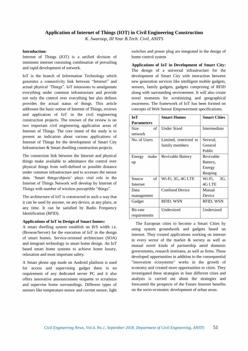
Civil Engineering News, Vol.4, No.1, September 2018, Department of Civil Engineering, ANITS 51
Application of Internet of Things (IOT) in Civil Engineering Construction
K. Swaroop, III Year B.Tech. Civil, ANITS
Introduction:
Internet of Things (IOT) is a unified division of
imminent internet consisting combination of prevailing
and rapid development of network.
IoT is the branch of Information Technology which
generates a connectivity link between “Internet” and
actual physical ‘Things”. IoT intensions to amalgamate
everything under common infrastructure and provide
not only the control over everything but also defines
provides the actual status of things. This article
addresses the basic notion of Internet of Things, reviews
and application of IoT in the civil engineering
construction projects. The renown of the review is on
two important civil engineering application areas of
Internet of Things. The core intent of the study is to
present an indication about various applications of
Internet of Things for the development of Smart City
Infrastructure & Smart dwelling construction projects.
The connection link between the Internet and physical
things make available to admittance the control over
physical things from well-defined or possible distance
under common infrastructure and to accesses the sensor
data. ‘Smart things/objects’ plays vital role in the
Internet of Things Network will develop by Internet of
Things with number of wireless perceptible “things”.
The architecture of IoT is constructed in such a way that
it can be used by anyone, on any device, at any place, at
any time. It can be satisfied by Radio Frequency
Identification (RFID).
Applications of IoT in Design of Smart homes:
A smart dwelling system establish on B/S width i.e.
(Browse/Server) for the execution of IoT in the design
of smart homes. Service-oriented architecture (SOA)
and integrant technology in smart home design. An IoT
based smart home systems to achieve home luxury,
relaxation and most important safety.
A Smart phone app made on Android platform is used
for access and supervising gadget there is no
requirement of any dedicated server PC and it also
offers innovative announcement etiquette to scrutinize
and supervise home surroundings. Different types of
sensors like temperature sensor and current sensor, light
switches and power plug are integrated in the design of
home control system
Applications of IoT in Development of Smart City:
The design of a universal infrastructure for the
development of Smart City with interaction between
new generation services like intelligent mobile gadgets,
sensors, family gadgets, gadgets comprising of RFID
along with surrounding environment. It will also create
novel moments for scrutinizing and geographical
awareness. The framework of IoT has been formed on
concepts of Web Sensor Empowerment specifications.
IoT
Parameters
Smart Homes Smart Cities
Size of
network
Under Sized Intermediate
No. of Users Limited, restricted to
family members
Several,
General
Public
Energy make
up
Revivable Battery Revivable
Battery,
Energy
Reaping
Source of
Internet
Wi-Fi, 3G, 4G LTE Wi-Fi, 3G,
4G LTE
Data
management
Confined Device Mutual
Device
Gadget RFID, WSN RFID, WSN
Bit-rate
requirements
Undersized Undersized
The European cities to become a Smart Cities by
using system groundwork and gadgets based on
internet. They created applications working on internet
in every sector of the market & society as well as
mutual novel kinds of partnership amid domestic
governments, research institutes, as well as firms. These
developed opportunities in addition to the consequential
"innovation ecosystems" works in the growth of
economy and created more opportunities to cities. They
investigated these strategies in four different cities and
analysis is carried out about the strategies and
forecasted the prospects of the Future Internet benefits
on the socio-economic development of urban areas.

Civil Engineering News, Vol.4, No.1, September 2018, Department of Civil Engineering, ANITS 52
Construction Materials from Waste
M. UshaRani, IV Year B.Tech. Civil, ANITS
With drastic increase in population the need for power
and utilization of construction materials also increased
in leaps and bounds. With modernisation the production
rates were also increased but on the other hand the
world is facing serious problems in dumping the waste
generated from the processes. Production of waste
materials (e.g.: coir pith, pond ash, brick powder, fly
ash etc.) are rapidly increasing day by day which is
imposing serious problems on health and socio
economical issues. .In order to reduce the impact on
environment, these materials can be used as
replacement material in constructions.
Coir Pith:
India is the largest coir producing country in the world
with 31,64,250 metric tonnes of coir pith is generated
annually. Coir pith is a by-product generated in the
process of fibre extraction from coconut husk in coir
manufacturing industry. For every ton of fibre
extracted, about two tons of coir waste is produced.
Disposal of this waste in the environment causes
unhygienic conditions. Coir pith possesses better
strength and it also reduces the swelling and shrinkage
of black cotton soil. Hence these days it is used in the
stabilization of soil. Coir pith has remarkable capacity
to absorb moisture.
Fig.1 Coir pith
Pond Ash:
Pond ash is a product obtained from thermal power
plants. India is a country which is heavily reliant on
thermal power plants for electricity. So availability of
pond ash is more which is the deposit is obtained from
the thermal power plants. In India 70 million tonnes of
pond ash is generated annually. This product can be
used in cement manufacturing and brick manufacturing,
part replacements of cement in mortar and concrete, in
embankment stabilization, filling in low lying areas,
dyke constructions. Use of pond ash not only reduces
pollution in environment but also increases the aesthetic
appearance of building.
Fig.2 Pond Ash
Brick Powder:
Brick powder, a waste material available in abundance
at brick kilns, is rich in silica and is available free of
cost. Brick powder is being successfully used in mortar
and concrete making from the past few decades. Partial
replacement of cement with brick powder in mortar has
showed that with use of brick powder the recycled-
aggregate mortar seemed to be superior in terms of
mortar-brick bond strength mainly because of its
rheological properties. Studies on use of brick powder
as stabilizer for black cotton soil showed that when
about 50% brick powder is mixed with black cotton soil
there has been significant increase in strength aspects of
the soil.
Fly Ash:
Fly ash is a coal combusted material of the particulates
(fine particles of burned fuel) that are driven out of
coal-fired boilers together with the fuel gases. The
generation of fly ash in India has increased from 68.88
million tonnes to 163.56 million tonnes in the span of
16 years from 1996-97 to 2012-13. This can used as a
replacement for Portland cement in concrete and
stabilization of soil .As fly ash greatly improves the
strength and durability of concrete, and reduces
swelling and shrinkage. It can be used as a option for
the stabilizing material for soil.
Fig. 4 Fly Ash

Civil Engineering News, Vol.4, No.1, September 2018, Department of Civil Engineering, ANITS 53
Solar Trapping Tree
A Vaghna, IV Year B.Tech. Civil, ANITS
Energy sources are becoming limited throughout the
world. The price of fuels is rising day by day. The
technology of renewable resources is an alternate
solution of energy sources. Solar energy is available in
abundance and considered as easiest and cleanest means
of tapping the renewable energy. The sun is constantly
sending energy to the earth and all we need to do is to
catch it and then use it.
A solar tree is a structure incorporating solar energy
technology on a single pillar, like a tree trunk. In the
name ‘Solar tree’, tree stands for Trees generating
Renewable Energy and Electricity. It may be called as a
solar artwork or a functional power generator.
Solar Tree is made of metal structure, resembling a tree
but the canopy is modified. Ithas solar panels at the top
instead of branches of real tree.The components
included in a solar tree are Solar panels, Long tower,
LED’s, Batteries and Stems for connecting panel.A
technique called Spiralling Phyllataxy is used in
designing of solar tree. It is a unique technique used
which provides a way to help the lower panels from the
shadow of upper ones so that every cell gets equal
amount of energy and it can track maximum power
from sun. Solar energy is collected by Solar panel.
To generate 2 MW power from a photovoltaic module
we require 10–12 acres of land for housing of only
panels but for the same amount of energy we require
only 0.10-0.12 acres of land in case of solar tree. It is
eco-friendly, reduces electricity bill and requires less
maintenance.
Fig: Solar tree near Wellington road in London
To fulfill the increasing energy demand of the world
and saving of land, solar tree is very successful and
should be implemented in populated countries like India
to provide electricity without the problem of power cut
and the extra energy can be provided to the grid. Solar
tree is an add-on solution for our future energy needs.

Civil Engineering News, Vol.4, No.1, September 2018, Department of Civil Engineering, ANITS 54
Urban Municipal Waste Management
Ch. Rahul Reddy, S. Shanmukha Rao, IV Year B.Tech. Civil, ANITS
Life Cycle assessment of Municipal Solid waste:
The life cycle of waste is often referred to as a journey
from when an item is put on the curb or placed in a
dumpster to when value is restored by creating usable
material or energy, or the waste is transformed into
emissions to water or air or into inert material placed in
a landfill. Waste minimization can be achieved in an
efficient way by focusing primarily on the 5Rs,
“reduce,” followed by “reuse”, “recycle” and then
“recover” and finally “remove”. The concept of
minimizing waste impacts in terms of quantity or ill-
effects, by reducing quantity of wastes, reusing the
waste products with simple treatments and recycling the
wastes by using it as resources to produce same or
modified products and recovery of energy/useful
product is usually referred to as 5R.
Benefits of 5R in the life Cycle of Solid Waste
Management:
Life cycle assessment (LCA) methodology was used to
determine the optimum municipal solid waste (MSW)
management strategy. The inclusion of 5R technique in
the life cycle assessment of SWM result into following
advantages
1. Demand for natural resources is reduced.
2. Emissions to environment are decreased (less
energy is used for reprocessing secondary
materials than for extraction of virgin
materials).
3. The amount of the solid waste is reduced and
smaller amounts of waste remain for disposal.
4. Decrease the burden on collection services as
well as on treatment and final disposal
facilities.
Disposal of Solid Waste:
Sanitary Landfills have also been widely unsuccessful
in countries like India because the landfill sites have a
very limited time frame of usage. The population of the
developing countries is another factor that detrimentally
impacts the function of landfill sites. As the population
keeps increasing, the garbage quantity also increases,
which, in turn, exhausts the landfill sites. Landfills are
also becoming increasingly expensive because of the
rising costs of construction and operation. Incineration
can greatly reduce the amount of incoming municipal
solid waste. However, incinerator ash may contain
hazardous materials including heavy metals and organic
compounds such as dioxins. Recycling and Recovery
(treatment/processing) plays a large role in solid waste
management. Recycling can be the first choice in solid
waste disposal. Recycling is the recovery and reuse of
materials from wastes. Solid waste recycling refers to
the reuse of manufactured goods from which resources
such as steel, copper, or plastics can be recovered and
reused. Recycling can also play a key role in the GHG
reductions that occur when recycled materials are used
instead of virgin materials, saving energy.
Greenhouse gases (GHG) are those that absorb and
emit infrared radiation in the wavelength range emitted
by Earth. In order, the most abundant greenhouse gases
in Earth's atmosphere are:
1) Water vapour (H2O)
2) Carbon dioxide (CO2)
3) Methane (CH4)
4) Nitrous oxide (N2O)
5) Ozone (O3)
6) Chlorofluorocarbons (CFCs)
7) Hydro fluorocarbons (incl. HCFCs and HFCs)
The major non-gas contributors to Earth’s greenhouse
effect are clouds because it absorb and emit infrared
radiation and thus have an effect on greenhouse gas
radioative properties. Clouds are water droplets or ice
crystals suspended in the atmosphere. The global
warming potential (GWP) depends on both the
efficiency of the molecule as a greenhouse gas and its
atmospheric lifetime. GWP is measured relative to the
same mass of CO2 and evaluated for a specific
timescale. Thus, if a gas has a high (positive) radiative
forcing but also a short lifetime, it will have a large
GWP on a 20-year scale but a small one on a 100-year
scale. Conversely, if a molecule has a longer
atmospheric lifetime than CO2 its GWP will increase
when the timescale is considered. Carbon dioxide is
defined to have a GWP of 1 over all time periods.
Reuse of recovered material generally requires less
energy than the use of virgin material. For example for
every ton of recycled paperboard packaging produced,
there is an overall net reduction of 3.6 metric tons of

Civil Engineering News, Vol.4, No.1, September 2018, Department of Civil Engineering, ANITS 55
carbon dioxide emission. In addition the amount of
energy that is wasted by not recycling paper, printed
material, glass, plastic and aluminium and steel cans is
equivalent to the output of 15 medium sized power
plants. Recycling also diverts waste from landfills and
offsets landfill methane emission in that manner. Pearce
and Brisson (1993) show that various economic
instruments can be used to balance the marginal costs
and benefits of recycling to arrive at an optimum level
of recycling.

Civil Engineering News, Vol.4, No.1, September 2018, Department of Civil Engineering, ANITS 56
The Jeddah Tower
G Raj Kumar, IV Year B.Tech. Civil, ANITS
The tallest building in the world is BurjKhalifa. But in
2020, this might be the wrong answer. Yeah, what you
read is correct. BurjKhalifa is going to be the second
tallest building, by giving its title to “Jeddah Tower” in
2020. The Jeddah Tower is located in the Jeddah city of
Saudi Arabia.
Jeddah tower is also known as the Kingdom tower. The
name for this structure is initially planned to be as Mile
high tower since initially it was planned to build this
structure to a total height of 1 mile. But the geological
considerations of the site limited its height to 1000m.
According to the recent update, the construction work
of the Jeddah Tower has been delayed due to the
financial issues and is going to be completed by the
year 2020. The construction has already reached the
66th floor and the superstructure concrete shell and the
cladding is going to be completed by the next year.
The main features of the Jeddah Tower comparing with
the Burj Khalifa are given in the Table-1:
Table-1 Main features of Jeddah Tower
Point of
Comparison Burj Khalifa
Jeddah Tower
(If executed as per
planned)
Architectural
tip 828m 1008m
Cost 1.6 Bn $(US) 1.23 Bn $(US)
Observatory
deck
555.7m (148th
Floor) 644m (157th Floor)
No. of floors 154 (163 with
inhabitable floors)
170 (252 with
inhabitable floors)
No. of lifts 59 57
Construction
period
06-01-2004 To
02-12-2010
01-04-2013 To
2020
Total floor
area 309473 m2 243886 m2
The Jeddah tower is designed by Adrian smith (also the
designer for Burjkhalifa) and Gordon Gill architecture.
The total quantity of concrete required for the
construction is approximately 5,00,000 m3 whose
quantity is equal to the concrete used for 6 Hoover
dams. The total steel used is 80,000 tonnes whose
quantity is equal to the steel used for 8 Eiffel towers.
The structure is used for different purposes such as
offices, hotels, residential apartments, tourism etc.
Jeddah tower has the largest observation deck in the
world which is the main advantage for the tourism.
The competition for the tallest is never going to end.
Sky is the limit is the foremost learning of the tall
structures.
Fig 1 Under construction - Jeddah tower
Fig 2 Proposed construction - Jeddah tower

Civil Engineering News, Vol.4, No.1, September 2018, Department of Civil Engineering, ANITS 57
Eco-BLAC Brick
(Pollution Free Bricks)
G Gowri Prasad, IV Year B.Tech. Civil, ANITS
By 2050 the population in India is expected to reach 1.5
billion people. It is anticipated that this increase in
population will place a substantial demand on the
housing stock and need for building materials. For
centuries, the clay fired brick has been the most popular
building material in India due to its local availability
and low cost.
India’s brick industry, spread out over 1,00,000 kilns
and producing up to 2 billion bricks a year. However,
negative environmental and social impacts
surrounding its production have raised and a number
of industrial wastes are being generated which are
often disposed in harmful ways to the population and
the environment.
Fig.1 Eco- BLAC Brick
Generally these clay bricks are fired to 1,000 degrees
Celsius.They consume a tremendous amount of
energy from coal and there’s also the issue that these
bricks are made completely of topsoil, so they are
depleting the amount of farmable land. Therefore here
is the solution for pollution free – “Eco BLAC Brick”
The Eco BLAC brick manufactured from industrial
wastes and requires no firing at all and makes use of
waste boiler ash that otherwise clog up landfills. The
Eco-BLAC brick performed better in all categories,
24% better in human health, 15% better in climate
change and 33% better in resources.
The Eco BLAC brickconsists of:
70 % - Boiler ash
20% -Clay
10 % -Lime
It is cured at ambient temperature, relying on “alkali-
activation technology” to give strength.
Fig.2 Boiler Ash
Advantages:
Early strength development (over 50% of 28
day strength after 1 day curing).
Low cost.
Maximum use of boiler ash in order to reduce
the landfills.
If the Eco BLAC bricks prove successful, that would
be good for India’s air quality as well as its food
security. Eco-BLAC Bricks was named one of the top
innovations of MIT$ 100K Entrepreneurship
Competition, 2015.
Civil Engineering News, Vol.4, No.1, September 2018, Department of Civil Engineering, ANITS 58
Why Can’t We Reuse?
Silaparasetti Jagadeesh Prasad, IV Year B.Tech. Civil, ANITS
Nowadays, construction activities are increasing day by
day. As a part of development and improvement,
number of old structures are being renovated. In this
process of improvement and renovation, huge amount
of building waste is being generated. Based on the
present situation in India, 90% of total building waste is
being used as landfill material only, as it is a very good
process of reusing of broken building material. But
there are other new techniques that these waste
materials can be used in different ways.
Reusing means to use the same material in different
place without changing its size and properties of the
material. Recycling is a process of converting waste
materials into new useful material,
Recycling is processed after the demolition of structure,
every material which can be recycled is collected and
transported to recycling plants, after recycling new
material is transported to work site.
The materials that can be recycled are steel
(reinforcement), concrete, plastics.
Concrete can be recycled by first crushing the
concrete into pieces and the crushed concrete
is separated according to the grain sizes. This
crushed stone like concrete pieces can be
effectively used in concrete in some percentage
of aggregates so that cost of concreting gets
reduced.
Steel is recycled by the best process which is
to melt the old steel materials at 1370oC to
1520oC and after melting this, it can be
converted into required shape and structure
with required dimensions.
Plastic is also recycled by making old plastic
material into small pieces based on the quality
of plastic, and they are converted into another
new product.
The greatest disadvantage for recycling is it increases
transportation costs and recycled material is not as
efficient as original.
On the other hand, reusable materials are to be pre
identified before the demolition of structure. The best
way to use these materials in other construction is to
share our available list of materials with dimensions,
quality of the item, and description of the item in online
source, where users can directly contact and get
benefited. In this way, reusing of old materials leads to
reduction in cost of construction, and it is also an
indirect way of helping the environment. The materials
that can be reused are aluminium (frames of windows),
timbers (doors, window doors, and cupboards), and
glass. These are some of the materials that can be
directly used from the old construction.
Advantages of reusing:
Reduces transportation cost
It reduces the overall cost of construction.
Originality of the material is retained
Both buyer and seller are benefited.
Recycling and reusing both are good processes for
effective utilisation of old material but reusing is better
as it has more advantages then the recycling process. It
is not just about one building it is an effective way of
managing of waste and building up our own new
generation of building in an efficient an effective
manner.
.

Civil Engineering News, Vol.4, No.1, September 2018, Department of Civil Engineering, ANITS 59
Brooklyn Bridge
Omkar Ganti IV Year B.Tech. Civil, ANITS
Out of all the Engineering Advances in the 1800s, The
Brooklyn Bridge Stands Out as Perhaps the Most
Famous and Most Remarkable. The bridge was
conceived by German immigrant John Augustus
Roebling in 1852.
Pioneering Efforts of Brooklyn Bridge
Perhaps the Greatest Innovation Dictated by John
Roebling Was the Use of Steel in The Construction of
The Bridge. Earlier Suspension Bridges Had Been Built
of Iron. This Is the First Bridge to Use Explosives in
Dangerous Underwater Foundation Called “Caissons”.
To Dig the Foundations for the Bridge’s Enormous
Stone Towers, Caissons, Enormous Wooden Boxes
with No Bottoms, Were Sunk in The River.
Compressed Air Was Pumped into Them, And Men
Inside Would Dig Away at The Sand and Rock on The
River Bottom. The Stone Towers Were Built atop The
Caissons, Which Sank Deeper into The River Bottom.
Caisson Work Was Extremely Difficult, And the Men
Doing It, called “Sand Hogs,” Took Great Risks. After
the caissons had been sunk to the river bottom, they
were filled with concrete, and the construction of the
stone towers continued above. When the towers reached
their ultimate height, 278 feet above high water, work
began on the four enormous cables that would support
the roadway.Spinning the cables between the towers
began in the summer of 1877 and was finished a year
and four months later. But it would take nearly another
five years to suspend the roadway from the cables and
have the bridge ready for traffic. By the time it was
finished in 1883, the bridge had cost about $15 million,
more than twice what John Roebling had originally
estimated. And while no official figures were kept on
how many men died building the bridge, it has been
reasonably estimated that about 20 to 30 men perished
in various accidents.
Fig :1- Brooklyn Bridge at the time of counstruction
Fig :2 - Brooklyn Bridge now

Civil Engineering News, Vol.4, No.1, September 2018, Department of Civil Engineering, ANITS 60
Precast Concrete Panels for Road Repairs
B. Gnanasagar, Ch.Ganesh, N. Mounika, T. Gayatri, P. Madhukumar, IV Year B.Tech. Civil, ANITS
Precast Concrete Panels (PCP) used for rapid repair of
existing concrete pavements and for rehabilitation of
existing concrete and asphalt pavements. PCP’s may
also be used for reconstruction or as an overlay
application. PCP’s applications include isolated repairs,
intersection and ramp rehabilitation, urban street
rehabilitation, and rehabilitation of longer mainline
pavement sections.
This article describes how precast concrete slabs can be
an effective way to conduct roadway repairs where time
is of the essence. Precast concrete is also advantageous
because it is durable, high-quality concrete that has a
high cement content cured under controlled conditions.
In addition, precast concrete has extra steel that
provides the strength necessary for transporting and
suspending the panels. Three different systems for
installing precast concrete highway slabs are being
currently used by state Departments of Transportation
(DOT) and toll-way authorities of U.S.A.
The first system, which is the patented Super-Slab
system, uses standard dowel bars for load transfer onto
engineered grades. The applications of this system
include Super-Slab in New York and New Jersey (see
Fig.1 & Fig.2).
The second system, which involves precast slabs under
sealed with polyurethane foam, and its use in highway
rehabilitation projects. The foam is used to anchor and
level the precast panels during placement (see Fig 3).
Fig.1 Super slab system in NewYork
The third method is a post-tensioned system that
consists of three different panel types: joint, central
stressing, and base panels. The panels are positioned
and then post-tensioned in a longitudinal direction. The
edges have shear keys that align during installation and
interlock the panels, thus preventing vertical movement
between joints. This system was adopted in a Caltrans
project in which 31 panels were placed in two nights on
one of the most heavily-trafficked areas in the U.S.
Fig.2 Super slab system in NewJersy
Fig.3 precast slabs under sealed with polyurethane foam
Fig.4 Post-tensioned system
These PCP systems can be fabricated and installed
successfully in developing countries also like India. A
wide range of projects have been constructed using
different pre-casters and different contractors. Overall,
there does not appear to be any concern about the long
term performance of the PCP system that are designed
well and installed well. By following these kinds of
systems in the road works the maintenance cost is
reduced and possess long life

Civil Engineering News, Vol.4, No.1, September 2018, Department of Civil Engineering, ANITS 61
Durability of Concrete with Partial Replacement of Cement by GGBS
N.SaiTeja, T.Sankeerthana, P.Durga Rao, P.Gnana Prakash, T.Satyavathi, IV Year B.Tech. Civil, ANITS
Concrete is probably the most extensively used
construction material in the world. Now-a-days the cost
of building materials is increasing, availability of
material is decreasing and due to the production of
cement, CO2 emission is also increasing. To overcome
all these problems, cement is partially replaced with
supplementary materials like Ground Granulated Blast
Furnace slag (GGBS), Fly ash, Silica fume, Metakaolin
etc.
Fig.1 Ground Granulated Blast Furnace Slag
The blast furnace slag is a by-product of the iron
industry which has Iron ore and coke resulting to a
molten slag. Molten slag floats above molten iron at a
temperature of about 1500o C to 1600o C. It has a
composition of about 30% to 40% SiO2 and about 40%
CaO, which is close to the chemical composition of
Portland cement. After the molten iron is collected for
manufacture of various metals, remaining molten slag
of mainly siliceous and aluminous residue is then water-
cooled rapidly resulting in the formation of a glassy
granulate. This glassy granulate is dried and ground to
the required size, which is known as ground granulated
blast furnace slag (GGBS).
The replacement of Portland cement with GGBS will
lead to significant reduction of carbon dioxide gas
emission. GGBS is therefore an environment friendly
material. Past researches concluded that 50% of the
Portland cement used in concrete can be replaced with
GGBS. GGBS concrete has better water impermeability
characteristics as well as improved resistance to
corrosion, sulphate and chloride attacks in concrete.
Thus, GGBS effectively can replace the Sulphate
Resisting Portland Cement (SRPC) in the market
because of its superior performance and less cost when
compared to SRPC. GGBS also reduces thermal
gradient in concrete, which prevents the occurrence of
micro-cracking in concrete.
Thus, Ground Granulated Blast Furnace Slag is an
effective supplementary material due to its specific
advantages for partially replacing cement in concrete

Civil Engineering News, Vol.4, No.1, September 2018, Department of Civil Engineering, ANITS 62
The Future of Transportation Engineering
R L N Harish, IV Year B.Tech. Civil, ANITS
This article will focus on the revolutionary changes in
transportation that are occurring right now and will be
continuing over the next decades. These changes
include (1) automation and connectivity, (2) alternative
fuels and fuel economy standards and (3) the
availability and use of so-called big data. First, vehicles
are becoming more automated and starting to
communicate. Basic automation and communication
technologies have been around for several decades.
Now there are driverless vehicles for off-road driving,
for agriculture, for space exploration, and for on-road
driving in traffic. Google (now named Waymo Division
within Google parent Alphabet) reports that its
autonomous vehicles have traveled more than three
million miles in automated mode. Although there are
numerous technical and policy barriers to overcome
before we routinely see self-driving vehicles on the
roads, we can expect to see increasing automation and
increasing communication between vehicles and
infrastructure. Most motor vehicle manufacturers are
already offering packages of automated driving aids and
improved sensors. A good example is a back-up camera
and warning to prevent slow-speed, backing-up
collisions. Benefits from all of this automation should
include fewer crashes, less congestion, better traveler
information, and more fuel-efficient driving.
Transportation engineers will have to change their
assumptions about traffic flow and driver behavior. As
noted earlier, vehicle automation and connectivity will
likely affect the amount of travel overall as individuals
with impairments or those having other tasks to perform
take advantage of driverless vehicles. At the same time,
telecommuting and better communications may reduce
overall transportation demand. Two other significant in-
vehicle changes are increased use of alternative fuels
and increasingly stringent fuel economy standards.
Most U.S. light-duty vehicles already operate with 10%
ethanol biofuels. In the future, we will likely have a
variety of fuels in regular use, including natural gas,
biofuels, and grid electricity. Different kinds of
transportation infrastructure will be required, such as
residential charging stations. For vehicles still relying
entirely on petroleum for fuel, sophisticated technology
and downsizing will be required to meet fuel economy
standards.
We are in the new era of big data and powerful
computing. Video cameras are cheaper and becoming
much more widespread. They can provide real-time
vehicle counts, vehicle speeds, incident detection, and
pavement condition. Smart phones provide a means of
tracking individual travelers in addition to
communicating with vehicles, infrastructure, and the
Internet. Transportation agencies should be able to rely
on private providers of volumes and travel times.
Unmanned aerial vehicles—drones—provide a new
way to gather information. Transportation engineers
must identify the best way to use this new flood of
information to better manage the transportation system.
This discussion focused on roadway transportation, but
these technologies will also revolutionize other modes.
In railroads, the newest step in automation is called
positive train control. In aviation, considerable
automation has already been introduced in cockpits, and
what is called next- generation air traffic control is
under development. In both aviation and railroads,
alternative fuels and big data are affecting how each
mode is managed and performs. In sum, we can expect
great change but also great opportunities. I think it is a
very exciting time to be civil engineer.
Source: Some Thoughts on the future of Transportation
Engineering by Chris Hendrickson

Civil Engineering News, Vol.4, No.1, September 2018, Department of Civil Engineering, ANITS 63
Soil Nailing
Ch.Soundarya, IV/IV B Tech Civil, ANITS
Soil nailing is a technique used to reinforce and
strengthen existing ground. It consists of installing
closely spaced bars into a slope or excavation as
construction proceeds from top down. It is an effective
and economical method of constructing retaining wall
for excavation support, support of hill cuts, bridge
abutments and high ways. This process is effective in
cohesive soil, broken rock, shale or fixed face
conditions.
Fig.1.Soil Nailing
Types of Nails
Driven Nails: Generally small-diameter nails (15-46
mm) with a relatively limited length (about 20 m) made
of mild steel that are closely spaced in the wall.
Grouted Nails: Steel bars, with diameters ranging from
15 to 46 mm, stronger than driven nails. These are
inserted into boreholes of 10-15 cm and then cement-
grouted.
Jet-grouted Nails: A composite of grouted soil and a
central steel rod, up to 40 cm thick.
Launched Nails: Nails between 25 and 38 mm in
diameter and up to 6 m or longer are fired directly into
the soil with a compressed-air launcher.
Machinery Used For Soil Nailing
1. Drilling Equipment.
2. Grout Mixing Equipment.
3. Shotcreting/Guniting Equipment.
4. Compressor
Materials Used for Soil Nailing are:
Steel Reinforcements: For corrosion protection, all steel
component shall be galvanized. If machine threading
after galvanization is unavoidable, then proper zinc
based coating shall be applied onto the thread.
Grout Mix: For conventional soil nail, the water cement
ratio of the grout mix ranges from 0.4 to 0.5. As most
cementitious grout will experience some grout
shrinkage, non-shrink additive can be used to reduce
breeding and grout shrinkage.
Shotcrete / Gunite: Shotcrete or gunite can be continuous flow of mortar or concrete mixes projected
at high speed perpendicularly onto the exposed ground
surface by means of pneumatic air blowing for dry mix
or spraying for wet mix.
Soil Nailing Applications:
1. Stabilization of railroad and highway cuts lopes.
2. Excavation retaining structures.
3. Tunnel portals in steep and unstable strained
slopes.
4. Construction and retrofitting of bridge
abutments with complex boundaries involving
wall support under piled foundations.
5. The stabilizing of existing over steep
embankments.
Soil nailing is an accepted technology, the theoretical
aspects of which are well understood and well reported
in technical literature. However, research indicates that
there are few practical guidelines available that offer a
comprehensive, experience-based insight into the
construction considerations that should be addressed
before a soil nail system design is finalized and
implemented.

Civil Engineering News, Vol.4, No.1, September 2018, Department of Civil Engineering, ANITS 64
Prefabricated Vertical Drains
Ch. Raghu Ram, Ch. Satya Srinivasa Rao, Year B.Tech. Civil, ANITS
Prefabricated vertical drain or wick drains are
composed of plastic encased by geotextiles for the
purpose of expediting the consolidation of slow
draining soils. The two main components of PVD are
Core which serves as a longitudinal flow path along the
drain and the Filter jacket which allows water to pass
into the core obstructing the entry of soil particles.
Prefabricated vertical drains (PVD) are commonly used
to decrease the drainage path within soft soils to
accelerate the time of primary consolidation.
Prefabricated vertical drains cause less soil
displacement with less disturbance to the soil mass. It is
very important to stabilize soft soil before commencing
any major construction work to prevent the settlement.
Many soft clay strata contain thin bands of silt or sands
which result in the instability of embankments due to
the horizontal spread of excess pore pressure vertical
drains relives the excess pore pressure and thus avoids
the occurrence of instability. The advantages of square
pattern are that it is more convenient to install and
manage on site. However, triangular pattern is the most
popular because it provides a more uniform
consolidation between drains than square pattern.
Fig.1 Prefabricated vertical drain
Fig.2 Cross-Section Without and With Vertical Drains
Fig.2 shows the soil stabilization with PVD’s combined
with a surcharge and a surcharge alone. In the soil
stabilized with PVD’s, the pore water is flowing
laterally to the nearest drain thereby shortening the pore
water travel distance, reducing the preloading time.
Whereas the soil without PVD’s the drainage path is
long and thus increases the consolidation time,
preloading time.

Civil Engineering News, Vol.4, No.1, September 2018, Department of Civil Engineering, ANITS 65
100 Percent Fly ash Concrete
N. Yesupadam and M. Yaswant Krishna, IV Year B.Tech. Civil, ANITS
More than 20 billion tons of concrete is produced
around the world every year in a manufacturing process
that contributes 5 to 10 percent of carbon dioxide to
global emissions, surpassed only by transportation and
energy as the largest producers of the greenhouse gas.
Fly ash binder does not require the high-temperature
processing of Portland cement, yet tests showed it has
the same compressive strength after seven days of
curing. It requires only a small fraction of the sodium-
based activation chemicals used to harden Portland
cement. Manufacturers often use a small amount of
silicon- and aluminum-rich fly ash as a supplement to
Portland cement in concrete. The industry typically
mixes 5 to 20 percent fly ash into cement to make it
green, but a significant portion of the mix is still
cement. Previous attempts to entirely replace Portland
cement with a fly ash compound required large amounts
of expensive sodium-based activators that negate the
environmental benefits and, in the end,, it was more
expensive than cement.
According to Taguchi analysis, a statistical method
developed to narrow the large phase space all the
possible states of a chemical composition, followed by
computational optimization to identify the best mixing
strategies. This greatly improved the structural and
mechanical qualities of the synthesized composites and
led to an optimal balance of calcium-rich fly ash, Nano
silica and calcium oxide with less than 5 percent of a
sodium-based activator.
Most of past works focused on type F fly ash, which is
derived from burning anthracite or bituminous coals in
power plants and has low calcium content. But globally,
there are significant sources of lower grade coal such as
lignite or sub-bituminous coals. Burning them results in
high-calcium, or type C, fly ash, which has been more
difficult to activate. The work provides a viable path for
efficient and cost-effective activation of this type of
high-calcium fly ash, paving the path for the
environmentally responsible manufacture of concrete.
Future work will assess such properties as long-term
behaviour, shrinkage and durability. It is suggested that
the same strategy could be used to turn other industrial
waste, such as blast furnace slag and rice hulls, into
environmentally friendly cementitious materials without
the use of cement.
The durable new concrete eliminates the use of cement,
which is known to be harmful to the environment.
Instead of cement, the fly ash is used as a binder in the
concrete. Traditionally, concrete is processed by mixing
cement with sand and gravel, which contributes
anywhere from 5 to 8 percent of greenhouse gas
emissions worldwide. Cement is the key ingredient in
concrete and to produce it requires extremely high
temperatures and a massive amount of energy. This new
development comes at a time when researchers around
the world are beginning to look at engineering on a
nano-sized scale, like researching concrete at the
molecular level.
To sustainably advance the construction industry, we
need to utilize the 'bottom-up' capability of
nanomaterials. To activate the fly and turn it into a
cement-like material capable of binding the concrete,
the team used graphene oxide, a recently discovered
nanomaterial, and combined it with the fly ash and
water. The combination creates a chemical reaction
which rearranges the atoms in the solution, creating
strongly bonded atoms in a durable, cement-like binder.
Design of the fly ash concrete is pervious, meaning that
water can pass through it. This has the benefit of
replenishing groundwater as well as lower potential for
flooding. Several tests were done on the concrete and
can withstand various kinds of weight loads and
temperatures. Other tests, like monitoring sensors
buried under the concrete, are still underway.
References:
1. Article by “Rice University”, Houston, Texas,
US. Published in “Science Daily”.
2. Article by “Washington State University
(WSU)”, Pullman, Washington, USA.

Civil Engineering News, Vol.4, No.1, September 2018, Department of Civil Engineering, ANITS 66
Anil Neerukonda Institute of Technology and Sciences
Newsletter published by Department of Civil Engineering
BBBoooaaarrrddd ooofff SSStttuuudddiiieeesss (((CCCiiivvviiilll EEEnnngggiiinnneeeeeerrr iiinnnggg)))
1. Prof. G. Appa Rao, Professor, Civil, I.I.T., Chennai, Member
2. Dr. B.V.S. Viswanadham, Professor, Civil, I.I.T., Bombay, Member
3. Dr. CNV Satyanarayana Reddy, Professor, Civil, Andhra University,
Visakhapatnam, Member
4. Sri. D. Kasi Visweswara Rao, Chef Engineer (Retd.), CRDA, Vijayawada,
Member
5. Prof. A. Ramamohan Rao,Professor, Civil, ANITS, Member
6. Mr. J. Vikranth, Associate Professor., Civil, ANITS, Member
7. Mr. M.K.S.S.Krishna Chaitanya, Assistant Prof., Civil, ANITS, Member
8. Mr. T. Kiran Kumar, Assistant Prof., Civil, ANITS, Member
9. Ms. P.V.R. Sravya, Assistant Prof., Civil, ANITS, Member
10. Mr. T.V. Viswateja, Assistant Prof., Civil, ANITS, Member
11. Dr. B.N.D. Narasinga Rao, Professor & Head, Chairman
EEEdddiiitttooorrriiiaaalll BBBoooaaarrrddd
Chief Editor:
Dr.B.N.D.Narasinga Rao, Professor & Head, Civil Engineering
Members:
1. J.Vikranth, Associate Professor, Civil 2. M.K.S.S.Krishna Chaitanya, Assistant Professor, Civil
3. Ch.Vineel, Assistant Professor, T & P Coordinator, Civil
4. P.Vandana Rao, Assistant Professor, Civil
5. M.Premchand, Assistant Professor, Civil
6. K.Suryanarayana, Assistant Professor, Co-Curricular
Activities Coordinator, Civil
7. J.Harshavardhana Reddy, Assistant Professor, Civil
8. P.V.R.K.Reddy, Assistant Professor, Civil
Student Members:
1. A.Vaghna, 315126508001 (IV/IV Civil)
2. G.Omkar, 315126508020 (IV/IV Civil)
3. J.Swetha, 315126508021 (IV/IV Civil)
4. N.Mounika, 315126508036 (IV/IV Civil)
5. S.Jagadish Prasad, 315126508065 (IV/IV Civil)
6. K.Jyothi Swaroop, 316126508024 (III/IV Civil)
7. M.Karthik, 316126508029 (III/IV Civil)
8. R.Sujini Lavanya , 316126508039 (III/IV Civil)
9. B.L.Sowjanya, 317126508004 (II/IV Civil)
10. K.Devi Renuka, 317126508025 (II/IV Civil)
Civil Engineering News