angle-of-arrival estimation of multipath signals in a passive coherent location system using...
TRANSCRIPT

Wireless Pers CommunDOI 10.1007/s11277-013-1542-9
Angle-of-Arrival Estimation of Multipath Signals in APassive Coherent Location System Using OFDM-BasedIlluminators
Meng-Chang Hua · Hsin-Chin Liu · Cheng-Han Hsu
© Springer Science+Business Media New York 2013
Abstract Terrestrial multipath interference is inevitably problematic in passive coherentlocation (PCL) systems because it can overwhelm target signals and cause detection errors.However, angle-of-arrival (AOA) information about multipath signals can be used to reducedetection errors in PCL systems. This work proposes a new method of identifying AOAmultipath components for PCL systems with OFDM-based illuminators. Use of a 3-elementarray deployed as an equilateral triangle enables accurate estimation of AOA information formultipath signals. Notably, the number of AOA estimations can far exceed the number ofarray elements. Simulation results confirm the effectiveness of the proposed method.
Keywords Angle-of-arrival estimation · Passive coherent location system · Overloadedarray · OFDM · DVB-T
1 Introduction
Detecting airborne targets in passive coherent location (PCL) systems using OFDM-basedilluminators has been studied in recent years [1,2]. Multipath interference is a major problembecause it degrades the target detection capability of a PCL system when large multipathcomponents mask weak target signals. Therefore, multipath interference suppression is animportant issue in PCL systems.
M.-C. Hua (B) · H.-C. Liu · C.-H. HsuDepartment of Electrical Engineering, National Taiwan University of Science and Technology,Taipei 106, Taiwane-mail: [email protected]
H.-C. Liue-mail: [email protected]
C.-H. Hsue-mail: [email protected]
123

M.-C. Hua et al.
Many proposed multipath suppression methods for minimizing multipath or direct pathinterference can be categorized as two types: time domain methods and spatial domainmethods [3–9].
Most methods of interference suppression via time domain are based on adaptive tech-niques such as the well-known least mean square (LMS), normalized least mean square, andrecursive least square (RLS) [3,4]. Other than that Colone et al. propose sequential cancel-lation algorithm (SCA) and extensive cancellation algorithm (ECA) using matrix inversionmethod [5,6]. A common processing concept in these methods is to reconstruct multipath sig-nals with time-delayed and Doppler-shifted replicas of the reference signal, which are thensubtracted from received signal. Although the radar receiver requires a reference antennadirected toward the illuminator, the reference signal is also affected by multipath interfer-ence, which degrades performance [10].
The second type methods usually process radar signals via spatial domain, such as usingbeamforming techniques to cancel multipath signals. In [7,8], beamforming techniques withangle constraints are used to null multipath signals and to preserve target signals. All of thesespatial approaches certainly require angle-of-arrival (AOA) estimation for either multipathor target signals.
With the knowledge of multipath AOA information, interference cancellation via thespatial domain becomes more feasible. However, none of the above studies investigated AOAestimation in PCL systems. Hence, this work addresses the problems of AOA estimation inPCL systems and proposes a robust and accurate method to estimate AOA for multipathsignals. Notably, the scope of this work excludes AOA estimation for targets.
The remainder of this paper is organized as follows. Section 2 describes AOA estimationproblems in PCL systems. Section 3 introduces the underlying concepts of the proposedmultipath AOA estimation method. Section 4 presents the results of computer simulationsused to confirm the efficacy of the proposed method. Section 5 draws conclusions.
2 Problem Statements
The AOA estimation of signals impinging on an antenna array has been a topic of greatinterest in array signal processing. Subspace techniques based on the eigen-structure ofan input covariance matrix are widely used in many fields and have rapidly developed inrecent decades. Subspace techniques have proven accurate and effective for AOA estimationin systems in which the number of impinging signals is smaller than the number of arrayelements. Unfortunately, this condition rarely occurs in PCL systems, which yields estimationfailure. This problem can be described as follows.
Consider that an antenna array receives signals from the same illuminator via L differentpaths; these signals are generally correlated. A de-correlation scheme is usually requiredbefore subspace AOA estimation. Assume that, after de-correlation, the array has M elements,and the spacing between elements is less than half the wavelength of the incident signals.The received signal vector of the array at the time instant t has the form
x(t) = As(t) + n(t) (1)
where A is the steering matrix, s(t) is the signal vector, and n(t) is the additive Gaussianwhite noise vector. The input covariance matrix is given by
E[x(t)xH (t)] = ARssAH + σ 2I (2)
123

Angle-of-Arrival Estimation of Multipath Signals
where Rss = E[s(t)sH (t)] is the signal covariance matrix. Since Rss is nonsingular and thecolumns of A are linearly independent because of their Vandermonde structure, Rxx is ofrank M . Let λ1, λ2, . . . , λM and e1, e2, . . . , eM denote the eigenvalues and eigenvectors ofRxx , respectively. If the number of incident signals exceeds or equals the number of arrayelements, i.e., L ≥ M , the signal subspace is the span of all the eigenvectors e1, e2, . . . , eM .In this environment, the lack of a noise subspace causes an overloaded array. Therefore,subspace methods are ineffective for AOA estimation.
In proposed approaches for dealing with overloaded systems [11–15], the cyclostationarityproperty of communication signals is exploited to extract desired signals with specific cyclefrequencies in order to null out co-channel interferences and additive noise with differentcycle frequencies. In these approaches, however, the number of remaining signals (desiredsignal and multipath signals reflected by the desired signals) with the same cycle frequency isstill limited to the number of antenna elements. Consequently, the aforementioned methodsare not suitable for PCL environments with massive multipath signals.
This work therefore proposes a new method of estimating the AOA information of multi-path signals by using only the three-element antenna array of a PCL system with an OFDM-based (e.g. DAB or DVB-T) illuminator. The number of impinging signals that can be esti-mated increases with the number of extracted pilots used in the frequency domain.
To validate the proposed method, a specific model for multipath scatters is required to beemployed. As stated in [16], several geometric models such as [17–20] are well investigated,and have been suggested for various types of environments. It is noteworthy that the Gaussiandistribution has been widely used in many fields [21,22]. For example, Ref. [21] uses theGaussian scattering channel to study the inter-carrier interference power of OFDM systems.However, Le [23] found that the hyperbolic distribution has a better fit to the measured data[24] toward the tail region than the Gaussian distribution, and derived an AOA probabilitydensity function (pdf) seen at the base station (BS) where random scatters are governed by ahyperbolic function. Subsequently, new hyperbolic AOA probability density function (pdf),power azimuth spectrum (PAS), time-of-arrival (TOA) pdf, and power delay spectrum (PDS)are derived later on [25]. This work employs the hyperbolic to model random scatters of anilluminator, testing the effectiveness of the proposed method.
3 Proposed Multipath AOA Estimation Method
An orthogonal frequency division multiplex (OFDM) symbol consisting of N subcarriers isgiven by
sn (t) = 1√N
N∑
k=1
S(n)k e j2π(k−1) 1
Tut, −Tg ≤ t ≤ Tu (3)
where S(n)k denotes the transmitted data symbol at the kth subcarrier of the nth OFDM symbol,
Tu is the duration of the useful part of the OFDM symbol, and � f = 1/Tu is the subcarrierspacing. Inter-symbol interference is prevented by inserting the cyclic prefix extension withtime length Tg before each OFDM symbol [26].
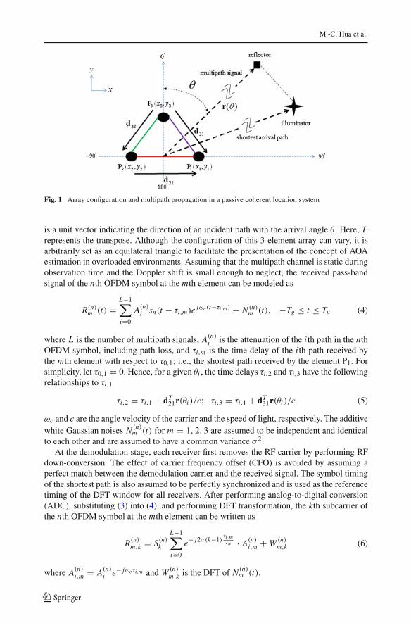
Figure 1 shows a PCL system with terrestrial multipath propagation between a receivearray and an illuminator. The notations in Fig. 1 are defined as follows: for a 3-element arraydeployed as an equilateral triangle, Pm(xm, ym) denotes the location of the mth element ona X–Y plane; di j = [x j − xi , y j − yi ]T is an orientation vector from the i th element to thej th element; the element spacings of any two elements are equal to d; r(θ) = [sin θ, cos θ ]T
123
M.-C. Hua et al.
Fig. 1 Array configuration and multipath propagation in a passive coherent location system
is a unit vector indicating the direction of an incident path with the arrival angle θ . Here, Trepresents the transpose. Although the configuration of this 3-element array can vary, it isarbitrarily set as an equilateral triangle to facilitate the presentation of the concept of AOAestimation in overloaded environments. Assuming that the multipath channel is static duringobservation time and the Doppler shift is small enough to neglect, the received pass-bandsignal of the nth OFDM symbol at the mth element can be modeled as
R(n)m (t) =
L−1∑
i=0
A(n)i sn(t − τi,m)e jωc(t−τi,m ) + N (n)
m (t), −Tg ≤ t ≤ Tu (4)
where L is the number of multipath signals, A(n)i is the attenuation of the i th path in the nth
OFDM symbol, including path loss, and τi,m is the time delay of the i th path received bythe mth element with respect to τ0,1; i.e., the shortest path received by the element P1. Forsimplicity, let τ0,1 = 0. Hence, for a given θi , the time delays τi,2 and τi,3 have the followingrelationships to τi,1
τi,2 = τi,1 + dT21r(θi )/c; τi,3 = τi,1 + dT
31r(θi )/c (5)
ωc and c are the angle velocity of the carrier and the speed of light, respectively. The additivewhite Gaussian noises N (n)
m (t) for m = 1, 2, 3 are assumed to be independent and identicalto each other and are assumed to have a common variance σ 2.
At the demodulation stage, each receiver first removes the RF carrier by performing RFdown-conversion. The effect of carrier frequency offset (CFO) is avoided by assuming aperfect match between the demodulation carrier and the received signal. The symbol timingof the shortest path is also assumed to be perfectly synchronized and is used as the referencetiming of the DFT window for all receivers. After performing analog-to-digital conversion(ADC), substituting (3) into (4), and performing DFT transformation, the kth subcarrier ofthe nth OFDM symbol at the mth element can be written as
R(n)m,k = S(n)
k
L−1∑
i=0
e− j2π(k−1)τi,mTu · A(n)
i,m + W (n)m,k (6)
where A(n)i,m = A(n)
i e− jωcτi,m and W (n)m,k is the DFT of N (n)
m (t).
123

Angle-of-Arrival Estimation of Multipath Signals
Rewriting (6) in a compact vector form, we have
R(n)m =
[R(n)
m,1, R(n)m,2, . . . , R(n)
m,N
]T = S(n)αmA(n)m + W(n)
m (7)
where S(n) is a N × N diagonal matrix of the nth OFDM symbol whose diagonal elementsare transmitted data symbols; i.e.,
S(n) =
⎡
⎢⎢⎢⎢⎣
S(n)1
S(n)2
. . .
S(n)N
⎤
⎥⎥⎥⎥⎦, (8)
αm = [a(τ0,m), a(τ1,m), . . . , a(τL−1,m)] is the N × L time delay matrix consisting of the i thcolumn time delay vector
a(τi,m) =[
1, e− j2πτi,mTu , . . . , e− j2π(N−1)
τi,mTu
]T
, (9)
A(n)m = [A(n)
0,m, A(n)1,m, . . . , A(n)
L−1,m]T is the complex amplitude vector, and W(n)m =
[W (n)m,1, W (n)
m,2, . . . , W (n)m,N ].
In OFDM systems, channel state information (CSI) is typically estimated using eithercontinual pilots or scattered pilots. This work uses the latter to estimate propagation delaysof multipath signals in each antenna element. For demonstration purposes, the illuminator ofthe PCL system is assumed to be a digital video broadcast-terrestrial (DVB-T) system [26],which is a widely used OFDM-based system.
The distribution of scattered pilots in a DVB-T system is shown in Fig. 2 [26]. Let s denotethe first scattered pilot position of an OFDM symbol, and the other pilots are placed everyp (p = 12 for DVB-T). The same pilot distribution is repetitively occurred every 4 OFDMsymbols. Next, assume that Np denotes the number of extracted scattered pilots. At the mthelement, the channel frequency responses (CFR) of scattered pilots of the nth OFDM symbolcan be obtained as
R(n)m =
(S(n))−1
E(n)R(n)m = αmA(n)
m + W(n)m (10)
where S(n) is a Np × Np diagonal matrix whose diagonal elements are the scattered pilotsymbols [In DVB-T systems, the pilot symbols are generated by a pseudo random binarysequence (PRBS)],
E(n) = {ei j}
i=1,...,Np, j=1,...,N ei j ={
1 j = s + (i − 1)p0 otherwise
(11)
Fig. 2 Distribution of scattered pilots
123

M.-C. Hua et al.
is the Np × N selection matrix indicating the scattered pilot entries of the nth OFDM symbol,αm is a Np × L Vandermonde matrix which contains Np selected rows of αm ; i.e.,
αm = [a(τ0,m), a(τ1,m), . . . , a(τL−1,m)];
a(τi,m) = e− j2π(s−1)τi,mTu
[1, e− j2πp
τi,mTu , . . . , e− j2π(Np−1)p
τi,mTu
]T
(12)
and W(n)m = (S(n)
)−1E(n)W(n)
m .As shown in [27], Eq. (10) has exactly the same form as the AOA estimation problem with
a uniform linear array. That is, the set of scattered pilots extracted from an antenna elementcan be viewed as a virtual array in the problem of estimating multipath propagation delay.Consequently, subspace methods such as MUSIC [28], root MUSIC [29], ESPRIT [30], etc.,can be used in (10) to estimate time delay.
In this work, time delays τi,m are estimated using three virtual arrays corresponding toelements P1, P2 and P3, where i = 0, 1, . . . , L − 1, m = 1, 2, 3.
Because the complex amplitude A(n)m varies slowly over time and can be assumed constant
for the accumulated OFDM symbols, the rank of the covariance matrix
Cm = E
[R(n)
m
(R(n)
m
)H]
(13)
is one. Hence, a spatial smoothing scheme must be performed before applying subspacemethods.
Spatial smoothing, which is now the most promising technique for de-correlating fullycorrelated signals, is only applicable in a uniform linear array. Because the extracted scatteredpilots are also uniformly spaced, spatial smoothing is also applicable in a pilot set.
Following the procedure of the forward spatial smoothing scheme [31], an uniform linearpilot set with Np pilots is divided into Ns maximum overlapping subsets of size M =Np − Ns+1. Let extracted pilots {1,2,…,M} forming the first sub-set and {2,3,…,M+1}forming the second subset, etc. Since the three pilot sets are processed in the same procedure,we drop the index m (indicate the mth antenna element) in (10), (12) and (13) to simplify thenotation. The kth subset can be written as
R(n)k = [R(n)
s , R(n)s+p, . . . , R(n)
s+(M−1)p]T = αsP(k−1)A(n) + W(n) (14)
where αs = [as(τ0), as(τ1), . . . , as(τL−1)] is a M × L matrix with the i th M × 1 vectoras(τi ) = e− j2π(s−1)τi /Tu [1, e− j2πpτi /Tu , . . . , e− j2π(M−1)pτi /Tu ]T , and Pk is the kth powerof the L × L diagonal matrix
P =
⎡
⎢⎢⎢⎣
e− j2πpτ0/Tu
e− j2πpτ1/Tu
. . .
e− j2πpτL−1/Tu
⎤
⎥⎥⎥⎦ . (15)
The kth subset covariance matrix is then given by
Ck = E[R(n)
k (R(n)k )H
]= αsPk−1CA
(Pk−1
)HαH
s + σ 2W I (16)
where CA = E[A(n)(A(n))H ] is the amplitude covariance matrix and I is an M × M identitymatrix. In an implementation aspect, an estimate of the subset covariance matrix is obtainedby averaging several OFDM symbols, i.e.,
123

Angle-of-Arrival Estimation of Multipath Signals
Ck = 1
Nos
Nos∑
n=1
R(n)k (R(n)
k )H (17)
where Nos denotes the number of accumulated OFDM symbols. The covariance matrixes ofall subsets are then averaged to obtain the forward-only smoothed covariance matrix
ˆC = 1
Ns
Ns∑
k=1
Ck = αs
[1
M
Ns∑
k=1
Pk−1CA
(Pk−1
)H]
αHs + σ 2
W I
= αs PCAPH αHs + σ 2
W I (18)
where P = [P0, P1, . . . , PNs−1] is a L×LNs block matrix and CA = diag {CA, CA, . . . , CA}is an LNs × LNs block diagonal matrix. If the two conditions are true: Ns ≥ L and M ≥L + 1, ˆC should be proven that it has the rank of L .
It is clearly to see that the rank of αs is equal to L because of its Vandermode structure.The columns of P can rearranged as
P =
⎡
⎢⎢⎢⎣
b(τ0) 0 · · · 00 b(τ1) · · · 0...
.... . .
...
0 0 · · · b(τL−1)
⎤
⎥⎥⎥⎦ (19)
where b(τi ) = [1, e− j2πpτi /Tu , . . . , e− j2π(Ns−1)pτi /Tu
]is a 1 × Ns row vector and 0 is a
vector with all zero elements. Apparently, while Ns ≥ L , both P and CA are of rank L .According to the rank property of the smoothed covariance matrix, the number of extractedpilots must satisfy Np ≥ 2L in order to successfully solve L paths.
Another advanced scheme for reducing the required number of pilots is forward/backwardspatial smoothing scheme [32], in which the minimum number of pilots needed to estimateL paths is only 3L/2. However, this issue is beyond the scope of this work. Hence, this workonly applies the forward spatial smoothing scheme to the three pilot sets extracted from thecorresponding antenna elements.
Given any one of the exact smoothed covariance matrix, its eigen-decomposition is givenby
ˆC =M∑
i=i
λi ei eHi = Es�sEH
s + En�nEHn (20)
where ei is the eigenvector corresponding to the eigenvalue λi , Es = [e1, e2, . . . , eL ], En =[eL+1, eL+2, . . . , eM ],�s = diag {λ1, λ2, . . . , λL }, and �n = diag {λL+1, λL+2, . . . , λM }.The columns vectors in Es and En span the signal and noise subspace, respectively. Based onthe orthogonality between the signal and noise subspace and as(τi ) in the signal subspace,it follows EH
n as(τi ) = 0 for i = 1, . . . , L . Hence, the spatial spectrum of the time delayestimation is given by
T (τ ) in dB = 10 log
(1
∥∥EHn as(τ )
∥∥2
)(21)
where the peaks appear are the estimates of the time delays.After all time delays are estimated, elements P1 and P2, P1 and P3, P3 and P2 can be
grouped as sub-arrays 1, 2, and 3, respectively. The estimated time differences of arrival
123

M.-C. Hua et al.
(TDOA) of the i th path at all sub-arrays are
�τ1 = τ2 − τ1,�τ2 = τ3 − τ1,�τ3 = τ3 − τ2. (22)
Notably, index i is not required since the AOA estimation of each path can be evaluatedindependently.
The estimated direction vector can be obtained by solving the following minimizationproblem:
arg minr(θ)
∥∥Dr(θ) − c�τ∥∥2 (23)
where D = [d21, d31, d32]T and �τ = [�τ1,�τ2,�τ3]T . Solving the above equation byleast squares methods gives
r(θ) = c(DT D)−1DT �τ . (24)
Although (23) does not constrain the estimated direction vector r(θ) as a unit vector, it doesnot bias the AOA estimation due to the equilateral triangle array configuration, which willbe explained below.
According to the vector definition shown in Fig. 1, the three orientation vectors d21, d31
and d32 are d[1, 0]T , d[cos π3 ,− sin π
3 ]T and d[− cos π3 ,− sin π
3 ]T , respectively. The termDTD, i.e., the linear transformation matrix, is exactly equal to 3d2/2I. Therefore, the leastsquare solution can be simplified as
r(θ) = c
(3d2
2
)−1
DT �τ , (25)
i.e., DTD affect only the length and not the angle of the estimated vector r(θ).The flow chart of the proposed method is shown in Fig. 3 and the detailed steps are as
follows:
(1) Calculate three CFR sets R(n)1 , R(n)
2 , and R(n)3 with Np scattered pilots extracted from
elements P1, P2, and P3, respectively.(2) Group each CFR set into Ns maximum overlapping subsets. Ns is defined as
⌊Np/2
⌋,
where �x� stands for the integer part of x .(3) Average all subset covariance matrices to obtain the forward covariance matrix.(4) Estimate all time delays τi,m for i = 0, 1, . . . , L − 1 and m = 1, 2, 3 with respect the
shortest path received by element P1 using MUSIC algorithm.(5) Group two of the three elements to form three sub-arrays, and then select a path and
calculate its corresponding TDOAs in these three sub-arrays.(6) Use the least square method to estimate the AOA of the path.(7) Go to step 5 until all paths are processed.
4 Simulation Results
4.1 Verification of The Proposed Using Hyperbolic Scattering Channel
The OFDM system used in this simulation follows the commercial DVB-T system adoptedin Taiwan, which is an 8-k mode (N = 8192), 6 MHz DVB-T broadcasting signal with abaseband sampling time tb of 7/48M seconds, and the minimum scatter pilot spacing p = 12.The deployment of the 3-element array and the illuminator is depicted in Fig. 4. The random
123

Angle-of-Arrival Estimation of Multipath Signals
Fig. 3 Flow chart of theproposed multipath AOAestimation scheme
scatters surrounding the illuminator are governed by a hyperbolic distribution. D = 50 kmand u = D1 + D2 are the propagation distances between the illuminator and the array viathe LoS and a scatter, respectively.
The incident angle θi , time delay with respect to the LoS τi , and SNR of multipaths aregenerated by the hyperbolic AoA pdf, ToA pdf, and PDS derived in [23] and [25], i.e.,
pHAoA(θ) = 1
π
∞∑
m=1
(−1)m−1/2 exp(−mτ 2)1
m+ τ cos(θ)√
π
∞∑
m=1
(−1)m−1/2
×(
1√m
)exp[−mτ 2 sin2(θ)]{1 + erf[τ√
m cos(θ)]} (26)
pHAoA(τn) =
π/2∫
0
Db
2.367sech
[D2
b(τn − sin θ)2
4
](τ 2
n − sin2 θ√τ 2
n − 1
)dθ (27)
123

M.-C. Hua et al.
Fig. 4 Sketch of the deploymentof the simulation environment
PDSH (τ ) = cP0σ0le2π2μ
D∫
−D
(1
μ − ξ+ 1
μ + ξ
)β
2.367sech
[β2 (μ − ξ)2
4
]dξ, (28)
where Db = Dβ, β = 1/σs is the control parameter of hyperbolic scatter distribution, andξ = D2 − D1. Note the x-axis in of the ToA pdf can be replaced by τi since it has the relationτi = τ0(τn − 1), where τ0 = D/c and τn is the propagation time ratio as defined in [25].
For radar applications, the illuminator and antenna array are usually located at high-altitudeplaces. In a large area with high antenna platforms, random scatters around the illuminator canbe aptly assumed sparse-typically 2–6. The time delays of scatters could also be long-spread.In the report of DVB-T transmission aspects [33], 6-path channel profiles are employed totheir simulation work. From this viewpoint, it is reasonable to assume L = 6 and Db = 5in this simulation. The corresponding hyperbolic AOA pdf, TOA pdf, and PDS are shown inFig. 5.
It is pointed out in [27] that the maximum time delay that can be estimated withoutambiguity (step 4) is limited by relation between the pilot spacing p and the duratation Tu ,i.e., τ < Tu/p. For our employed DVB-T system Tu = 1.2 ms and p = 12 (minimum), timedelays cannot be larger than 99.5µs. However, time delays generated by the hyperbolic ToApdf shown in Fig. 5 have approximately a probability of 95 % smaller than 99.5µs. The threeparameters of the channel profile from a single generation are listed in Table 1. It should benoted that τi,2 and τi,3 can be calculated by Eq. (5).
Following the flow chart shown in Fig. 3 step by step, Fig. 6 shows the time delay estima-tions for the three antenna elements using MUSIC algorithm. The peaks shown in the threesub-figures indicate the time delay estimates τi,1, τi,2, and τi,3 for all multipath indices, andare then easily extracted by a differential method. Those time delay estimates are groupedpath-by-path to obtain the TDOA between the antenna elements. Using the least squaremethod, the AOA estimations of the 6 multipaths are compared with the actual incident
123

Angle-of-Arrival Estimation of Multipath Signals
Fig. 5 Hyperbolic AOA pdf, TOA pdf, and PDS when D = 50 km, Db = 10. The SNR of the signal via theLoS is 20 dB
Table 1 List of the threeparameters of 6-path propagationchannel via a single generation(arranged in an ascending orderfor the time delay parameter)
Multipath index i 0 1 2 3 4 5
Incident angle θi (◦) 12.3 −0.2 −0.9 12.9 −4.54 8.1
Time delay τi,1 (µs) 11.8 36.8 42 48.9 71.8 78.3
SNR (dB) 16.7 12.2 11.2 10.1 5.3 3.8
angles and shown in Table 2. This result verifies that the proposed method can successfullyestimate the AOA of multipath signals in the hyperbolic scattering channel with specificchannel parameters.
4.2 Accuracy Evaluation via Numerical Analysis
Four numerical simulations are used to verify the accuracy of proposed method. The firstsimulation evaluates AOA estimation capability in terms of the accuracy of a 3-elementarray under overloaded conditions. The next three simulations further investigated how AOAestimation accuracy is affected by three major factors: element spacing d , scanning resolutionts , and the number of extracted pilots Np . Scanning resolution ts is defined as the minimuminterval of the x-axis in MUSIC spectrums for time delay estimation.
For all simulations, some common simulation parameters are set and described as follows.The OFDM system uses an 8-k mode (N = 8192), 6 MHz DVB-T broadcasting signal witha baseband sampling time tb of 7/48M seconds. When only the forward spatial smoothing isperformed for de-correlation, Ns is set as
⌊Np/2
⌋to estimate the maximum number of paths
for a given Np . The covariance matrix is estimated by using 200 OFDM symbols insteadof (13). For each realization, the actual angle of each randomly generated incident path isbetween −π and π . The empirical CDF of AOA estimation error is obtained from 10000
123

M.-C. Hua et al.
Fig. 6 Result of time delay estimations for the three antenna elements using MUSIC algorithm
Table 2 List of the estimatedand actual angles
Multipath index i 0 1 2 3 4 5
Incident angle θi (◦) 12.3 −0.2 −0.9 12.9 −4.54 8.1
Estimated angle θi (◦) 13.4 −1.8 −2.7 13.6 −8.6 9.6
realizations. Similarly, the root mean square error (RMSE) of AOA and TDOA estimationis calculated with 10000 simulation results per signal to noise ratio (SNR). The SNR of thei th path is defined as σ 2
i /σ 2, where σ 2i and σ 2 denote the signal power and the noise power,
respectively. To examine the accuracy of the proposed AOA estimation method at each fixedSNR environment, the powers of all impinging multipath signals are assumed equal, so thatthe SNR of all impinging multipath signals are the same.
In the first numerical analysis, we compared accuracy under different L values againstdifferent SNRs. The parameters ts, d , and Np are fixed at tb/70, 20 m, and 60, respectively.Five numbers of incident paths L = 1, 5, 10, 15, and 20 are tested in different SNRs. Figure 7shows the RMSE of the AOA estimations under different SNR values versus L . The RMSEsat all SNRs slightly increase as the number of incident paths increases from 1 to 20. Moreover,the AOA estimation error is satisfactory (near 1◦) as long as the SNR is sufficient. With 20incident paths and SNR = 0 dB, the RMSE of AOA estimations approaches 10◦. However,Fig. 7 shows that the number of AOA estimations can exceed the number of elements; thatis, even for low SNR multipaths, the AOA estimation accuracy of the proposed method isstill acceptable in terms of RMSE.
According to the derivation in Sect. 3, an AOA estimate is calculated from the TDOAestimates of the sub-arrays. This implies that the accuracy of the AOA estimation may berelated to that of the time delay estimation. Since the time delay is estimated by the spectralMUSIC algorithm, the scanning resolution ts is an important factor in TDOA performance.
123

Angle-of-Arrival Estimation of Multipath Signals
2 4 6 8 10 12 14 16 18 20
100
101
Number of incident paths (L)
AO
A R
MSE
(de
gree
)
SNR=0 dBSNR=5 dBSNR=10 dBSNR=15 dBSNR=20 dB
Fig. 7 RMSE of AOA estimation under various SNR values against the number of incident paths
Fig. 8 RMSE of a TDOA and b AOA estimation under different scanning resolutions against SNR
Therefore, the appropriate scanning resolution is determined by first examining the RMSEsof TDOA and AOA for different scanning resolutions against SNR.
Parameters L , d , and Np are fixed at 20, 20 meters, and 60, respectively. Figure 8 comparesestimation accuracy among the four scanning resolutions and the Root MUSIC algorithm.The results are similar for low SNR cases. For high SNR cases, however, the RMSE ofTDOA slightly improves at scanning resolutions lower than tb/10. Notably, although theroot MUSIC algorithm does not obtain the best performance improvement, it substantiallyreduces computational complexity.
This simulation compared estimation accuracy under varying d . Parameters L , ts , and Np
are fixed at 20, tb/70, and 60, respectively. Figure 9 shows that a large array size greatlyimproves the RMSE performance of AOA estimation, especially when SNR is low. Notably,increasing element spacing does not improve RMSE of TDOA.
This numerical simulation confirms that, although enlarging the element spacing does notaffect TDOA estimation performance but improves AOA estimation performance. This resultis justified by deriving the relation between the square error of an estimated direction vector,element spacing, and TDOA estimation error. The estimated TDOA vector in (23) can beexpressed as
123

M.-C. Hua et al.
Fig. 9 RMSE of a TDOA and b AOA estimation under different element spacings against SNR
�τ = Dr(θ)/c + ε (29)
where ε is a 3 × 1 vector whose entries are the TDOA estimation errors of the sub-arrays.The square error can be expressed as a function of d and ε:
∥∥∥r(θ) − r(θ)
∥∥∥2 = c2εT D(DT D)−1(DT D)−1DT ε = 4
9d2 c2εT AAT ε (30)
where A = D/d . The square error is clearly inversely proportional to d , which justifies theresult in Fig. 9.
Although the large array size improves the performance of the proposed method, imple-mentation issues and channel properties limit the maximum size of the array. In array signalprocessing, increasing the number of elements increases the array aperture size and effi-ciently improves the performance of AOA estimation. Similarly, many scattered pilots canbe exploited to improve TDOA and AOA performance but at the cost of increased computa-tional complexity.
Figure 10 compares estimation accuracy under varying Np . The comparison results indi-cate that both TDOA and AOA errors reduce in low SNR cases when the number of extractedpilots increases.
Theoretically, the number of multipath signals that can be solved depends on the numberof extracted pilots. For a given Np pilots, the number of incident paths cannot exceed
⌊Np/2
⌋
when only the forward spatial smoothing is used.In a conventional AOA estimation problem, applying a spatial smoothing scheme to an
array reduces the array aperture, which degrades performance, especially when the number ofsignals approaches the limit of a spatially smoothed array. Hence, a simulation that examineseffects of aperture size is necessary.
This simulation presented a CDF comparison of AOA estimation error with Np = 60and the range of L between 3 and 30. Figure 11a shows that the CDF of AOA estimationerror of L = 30 is the worst because the number of incident paths is at the boundary value(�60/2� = 30). Increasing the value of Np , one can easily see that the AOA estimation errorof L = 30 significantly reduced as shown in Fig. 11b, where Np = 90. Since commonexisting OFDM-based systems, such as DAB and DVB-T, have sufficient available pilots,the proposed method is applicable in PCL systems.
123

Angle-of-Arrival Estimation of Multipath Signals
Fig. 10 RMSE of a TDOA and b AOA estimation under various Np against SNR
Fig. 11 Empirical CDF of AOA estimation error for various L with a Np = 60, b Np = 90. SNR = 20 dBfor all incident paths. Note that in a the curves except L = 30 are distributed near zero, and in b all curves arealmost overlapped
5 Conclusions
This work proposed a new method of using a 3-element array antenna to estimate the AOAof multipath signals from an OFDM-based illuminator (e.g., DVB-T or DAB). Using ourapproach, the number of AOA estimations is limited by the number of extracted pilots in thefrequency domain. Because of the massive pilot number in an OFDM modulation system(e.g., in an 8k mode DVB-T system, the number of scattered pilots is 576), the number ofmultipath AOA estimations can far exceed the number of antenna elements. This advantageis very attractive for a PCL system using OFDM-based illuminators.
Acknowledgments The authors would like to thank the anonymous reviewers for their valuable and con-structive comments, which helped to improve the presentation of the paper. This work is partially supportedby the National Science Council of Taiwan under grant no. NSC 102-2221-E-011-093 and NSC 102-2623-E-155-002-D.
References
1. Berger, C. R., Demissie, B., Heckenbach, J., Willett, P., & Shengli, Z. (2010). Signal processing for passiveradar using OFDM waveforms. IEEE Journal of Selected Topics in Signal Processing, 4, 226–238.
123

M.-C. Hua et al.
2. Sen, S., & Nehorai, A. (2011). Adaptive OFDM radar for target detection in multipath scenarios. IEEETransactions on Signal Processing, 59, 78–90.
3. Wu, M., Shan, T., & Zhuo, Z. (2011). An adaptive filter with discrete distribution structure in DTV basedpassive radar. In International conference on instrumentation, measurement, computer, communicationand control (pp. 755–758).
4. Kui, W., Ran, T., Yongfeng, M., & Tao, S. (2006). Adaptive multipath cancellation algorithm in passiveradar. In Proceedings of of the CIE international conference on radar (pp. 1–4).
5. Colone, F., Cardinali, R., & Lombardo, P. (2006). Cancellation of clutter and multipath in passive radarusing a sequential approach. IEEE conference on radar (pp. 393–399).
6. Colone, F., O’Hagan, D. W., Lombardo, P., & Baker, C. J. (2009). A multistage processing algorithmfor disturbance removal and target detection in passive bistatic radar. IEEE Transation on Aerospace andElectronic Systems, 45, 698–722.
7. Zhu, J., Hong, Y., & Tao, L. (2007). Adaptive beamforming passive radar based on FM radio transmitter.In IET International conference on radar systems (pp. 1–4).
8. Jiabing, Z. & Yi, H. (2011). Optimization of spatial filter for DPI and multipath interferences in passiveradar. In IEEE CIE International conference on radar (pp. 1020–1024).
9. Fabrizio, G., Colone, F., Lombardo, P., & Farina, A. (2009). Adaptive beamforming for high-frequencyover-the-horizon passive radar. IET Radar, Sonar & Navigation, 3, 384–405.
10. Colone, F., Cardinali, R., Lombardo, P., Crognale, O., Cosmi, A., Lauri, A., et al. (2009). Space-timeconstant modulus algorithm for multipath removal on the reference signal exploited by passive bistaticradar. IET Radar, Sonar & Navigation, 3, 253–264.
11. Schell, S. V., Calabretta, R. A., & Gardner, W. A. (1989). Cyclic MUSIC algorithms for signal-selectivedirection finding. In Proceedings of IEEE ICASSP89 (pp. 2278–2281).
12. Kim, K., Sarkar, T. K., Wang, H., & Salazar-Palma, M. (2004). Direction of arrival estimation basedon temporal and spatial processing using a direct data domain (D3) approach. IEEE Transactions onAntennas and Propagation, 52, 533–541.
13. Xu, G., & Kailath, T. (1992). Direction-of-arrival estimation via exploitation of cyclostationarity—Acombination of temporal and spatial processing. IEEE Transactions on Signal Processing, 40, 1775–1786.
14. Gardner, W. A. (1986). Measurement of spectral correlation. IEEE Transactions on Acoustics, Speech,and Signal Processing, ASSP–34, 1111–1123.
15. Gardner, W. A. (1988). Simplification of MUSIC and ESPRIT by exploitation of cyclostationarity. Pro-ceedings of the IEEE, 76, 845–847.
16. Janaswamy, R. (2002). Angle and time of arrival statistics for the Gaussian scatter density model. IEEETransactions on Wireless Communications, 1, 488–497.
17. Ertel, R. B., & Reed, J. H. (1999). Angle and time of arrival statistics for circular and elliptical scatteringmodels. IEEE Journal on Selected Areas in Communications, 17, 1829–1840.
18. Bevan, D. D. N., Ermolayev, V. T., Flaksman, A. G., & Averin, I. M. (2004). Gaussian channel model formobile multipath environment. EURASIP Journal on Applied Signal Processing, 2004, 1321–1329.
19. Petrus, P., Reed, J. H., & Rappaport, T. S. (2002). Geometrical-based statistical macrocell channel modelfor mobile environments. IEEE Transactions on Communications, 50, 495–502.
20. Suzuki, H. (1977). A statistical model for urban radio propogation. IEEE Transactions on Communica-tions, 25, 673–680.
21. Le, K. N. (2008). Bounds on inter-carrier interference power of OFDM in a Gaussian scattering channel.Wireless Personal Communications, 47, 355–362.
22. Le, K. N., Dabke, K. P., & Egan, G. K. (2001). Signal detection using non-unity kernel time-frequencydistributions. Optical Engineering, 40, 2866–2877.
23. Le, K. N. (2007). A new formula for the angle-of-arrival probability density function in mobile environ-ment. Signal Processing, 87, 1314–1325.
24. Pedersen, K. I., Mogensen, P. E., & Fleury, B. H. (2000). A stochastic model of the temporal and azimuthaldispersion seen at the base station in outdoor propagation environments. IEEE Transactions on VehicularTechnology, 49, 437–447.
25. Le, K. N. (2009). On angle-of-arrival and time-of-arrival statistics of geometric scattering channels. IEEETransactions on Vehicular Technology, 58, 4257–4264.
26. ETSI EN 300 744. (2009). Digital video broadcasting (DVB); framing structure, channel coding andmodulation for digital terrestrial television, v1.6.1.
27. Oziewicz, M. (2005). On application of MUSIC algorithm to time delay estimation in OFDM channels.IEEE Transactions on Broadcasting, 51, 249–255.
28. Schmidt, R. (1986). Multiple emitter location and signal parameter estimation. IEEE Transactions onAntennas and Propagation, 34, 276–280.
123

Angle-of-Arrival Estimation of Multipath Signals
29. Rao, B. D., & Hari, K. V. S. (1989). Performance analysis of root-MUSIC. IEEE Transactions on Acoustics,Speech, and Signal Processing, 37, 1939–1949.
30. Roy, R., & Kailath, T. (1989). ESPRIT-estimation of signal parameters via rotational invariance tech-niques. IEEE Transactions on Acoustics, Speech, and Signal Processing, 37, 984–995.
31. Shan, T.-J., Wax, M., & Kailath, T. (1985). On spatial smoothing for direction-of-arrival estimation ofcoherent signals. IEEE Transactions on Acoustics, Speech, and Signal Processing, 33, 806–811.
32. Pillai, S. U., & Kwon, B. H. (1989). Forward/backward spatial smoothing techniques for coherent signalidentification. IEEE Transactions on Acoustics, Speech, and Signal Processing, 37, 8–15.
33. TR Patent 101,190. (2009). Digital video broadcasting (DVB); implementation guidelines for DVB ter-restrial services; transmission aspects.
Author Biographies
Meng-Chang Hua was born in Changhua, Taiwan, in 1986. Hereceived the B.S. degrees in electrical engineering from the NationalTaiwan University of Science Technology, Taipei, Taiwan, in 2006, andis currently working toward the Ph.D. degree in electrical engineeringat the National Taiwan University of Science Technology. His researchinterests include wireless communications, array signal processing,smart antennas, and RFID systems.
Hsin-Chin Liu received the B.S. degree in communication engineer-ing from National Chiao Tung University, Taiwan, in 1989, and theM.S. and Ph.D. degree in electrical engineering from the Pennsylva-nia State University, University Park, 1993 and 2003, respectively. Hehas been a Software Engineer with Alcatel, Taiwan, a Hardware Engi-neer with Siemens, Taiwan, and a Member of Research Staff with theComputer Center, National Dong Hwa University, Taiwan. He is cur-rently an Associate Professor with Department of Electrical Engineer-ing, National Taiwan University of Science and Technology, Taipei,Taiwan. His current research interests include wireless communica-tions, smart antenna technologies, software defined radio, and RFIDsystems.
123

M.-C. Hua et al.
Cheng-Han Hsu was born in Taichung, Taiwan, in 1984. He receivedthe B.S. degrees in electrical engineering from the National Chung-Cheng University, Chua-Yi, Taiwan, in 2005, and is currently workingtoward the Ph.D. degree in electrical engineering at the National Tai-wan University of Science Technology. His research interests includewireless communications, array signal processing, smart antennas, andRFID systems.
123