anew chapter in precise orbit determination · 2017-04-08 · chapter in precise orbit...
TRANSCRIPT
IN NOVAT I ON
"Innovation" is a regular column in GPS World featuring discussions on recent advances in CPS technology and its applications as well as on the fundamentals of CPS positioning. This month we present an article on the use of CPS receivers on board orbiting spacecraft to determine their orbits with unprecedented accuracy. Our author is Thomas Yunck, Deputy Manager of the Tracking Systems and Applications Section of Caltech's Jet Propulsion Laboratory in Pasadena, California.
This column is coordinated by Richard Langley and Alfred Kleusberg of the Department of Surveying Engineering at the University of New Brunswick. We appreciate receiving your comments as well as suggestions of topics for future columns.
The claim that we can track the position of a bulky earth satellite continuously with an accuracy of a few centimeters may seem about as plausible as the suggestion that it might be desirable to do so. But space-based altimetry for ocean circulation experiments requires that level of accuracy - and the Global Positioning System (GPS) may be the only practical way to achieve it.
New orbit estimation techniques made possible by GPS differ in fundamental ways from those in use since Sputnik. And although the GPS system design dates to the mid-I 970s, we have only recently recognized the potential of these techniques. This is just one of the startling bonuses that have turned GPS into something of a windfall for earth science.
The essential difference GPS offers is comprehensive coverage. Never before has it
56 GPS WORLD October 1992
ANew Chapter in Precise Orbit Determination T. P. Yunck
Jet Propulsion Laboratory California Institute of Technology
been possible to track an earth satellite in three dimensions without interruption. But by placing a GPS receiver aboard the satellite, we can observe its true motion and reconstruct its trajectory in great detail without knowledge of the forces acting on it. Consequently, orbit accuracy need not be degraded by unpredictable satellite dynamics. Only the accuracy of the GPS carrierphase observable, which can be better than I centimeter for a !-second duration observation, ultimately limits "user orbit" accuracy.
ORBIT ACCURACY In recent years, the needs of space-based altimetry for the study of global ocean circulation have stimulated advances in low-altitude precise orbit determination. Examples of recent ocean altimetric satellites include Seasat ( 1978); Geosat ( 1985-1990); ERS-1, the first European Remote Sensing satellite, launched in 1991; and the U .S.-French TOPEXiPoseidon sateiiite, launched this past August.
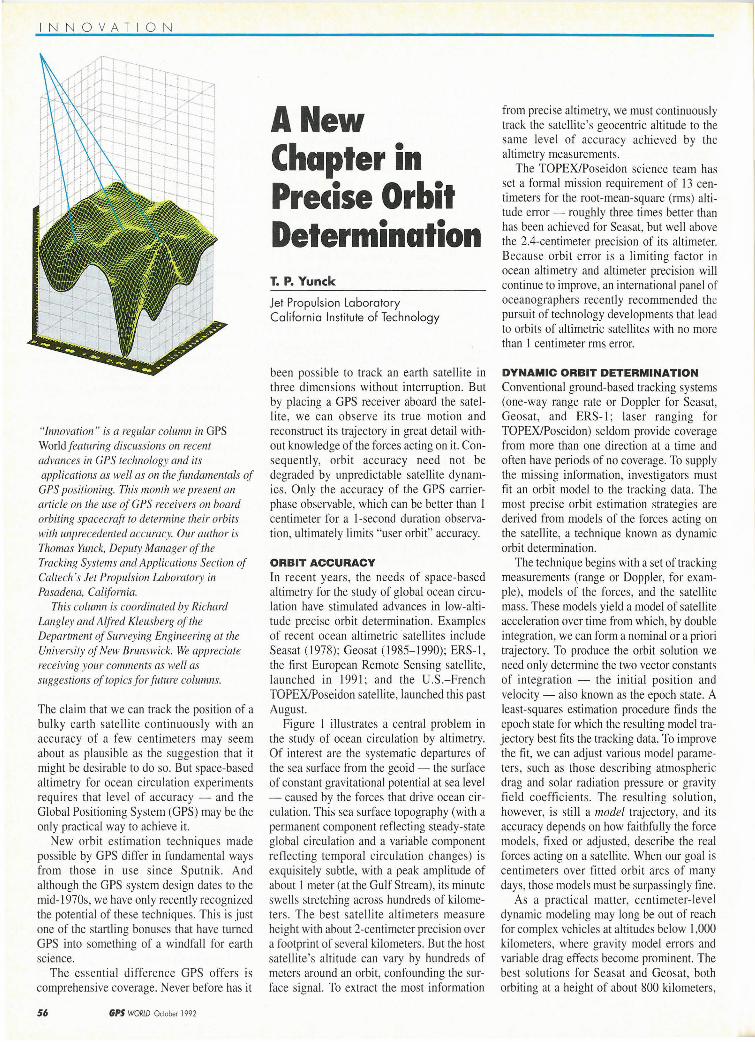
Figure 1 illustrates a central problem in the study of ocean circulation by altimetry. Of interest are the systematic departures of the sea surface from the geoid - the surface of constant gravitational potential at sea level - caused by the forces that drive ocean circulation. This sea surface topography (with a permanent component reflecting steady-state global circulation and a variable component reflecting temporal circulation changes) is exquisitely subtle, with a peak amplitude of about I meter (at the Gulf Stream), its minute swells stretching across hundreds of kilometers. The best satellite altimeters measure height with about 2-centimeter precision over a footprint of several kilometers. But the host satellite's altitude can vary by hundreds of meters around an orbit, confounding the surface signal. To extract the most information
from precise altimetry, we must continuously track the satellite's geocentric altitude to the same level of accuracy achieved by the altimetry measurements.
The TOPEX/Poseidon science team has set a formal mission requirement of 13 centimeters for the root-mean-square (rms) altitude enw- roughly three times better than has been achieved for Seasat, but well above the 2.4-centimeter precision of its altimeter. Because orbit error is a limiting factor in ocean altimetry and altimeter precision will continue to improve, an international panel of oceanographers recently recommended the pursuit of technology developments that lead to orbits of altimetric satellites with no more than 1 centimeter rms error.
DYNAMIC ORBIT DETERMINATION Conventional ground-based tracking systems (one-way range rate or Doppler for Seasat, Geosat, and ERS-1; laser ranging for TOPEX/Poseidon) seldom provide coverage from more than one direction at a time and often have periods of no coverage. To supply the missing information, investigators must fit an orbit model to the tracking data. The most precise orbit estimation strategies are derived from models of the forces acting on the satellite, a technique known as dynamic orbit determination.
The technique begins with a set of tracking measurements (range or Doppler, for example) , models of the forces , and the satellite mass. These models yield a model of satellite acceleration over time from which, by double integration, we can form a nominal or a priori trajectory. To produce the orbit solution we need only determine the two vector constants of integration - the initial position and veiocity - aiso known as the epoch state. A least-squares estimation procedure finds the epoch state for which the resulting model trajectory best fits the tracking data. To improve the fit , we can adjust various model parameters, such as those describing atmospheric drag and solar radiation pressure or gravity field coefficients. The resulting solution, however, is still a model trajectory, and its accuracy depends on how faithfully the force models, fixed or adjusted, describe the real forces acting on a satellite. When our goal is centimeters over fitted orbit arcs of many days, those models must be surpassingly fine .
As a practical matter, centimeter-level dynamic modeling may long be out of reach for complex vehicles at altitudes below I ,000 kilometers, where gravity model errors and variable drag effects become prominent. The best solutions for Seasat and Geosat, both orbiting at a height of about 800 kilometers,
ALTIMETER
h OCEAN SURFACE
TOPOGRAPHY
REFERENCE ELLIPSOID
Figure 1. A major challenge in interpreting precise ocean altimetry data is the removal of satellite altitude variations, thereby exposing sea surface topography with a precision comparable to that of the altimeter measurements.
are accurate radially to 25-40 centimeters. Scientists chose TOPEX/Poseidon 's relatively high altitude of 1,336 kilometers primarily to reduce dynamic model error.
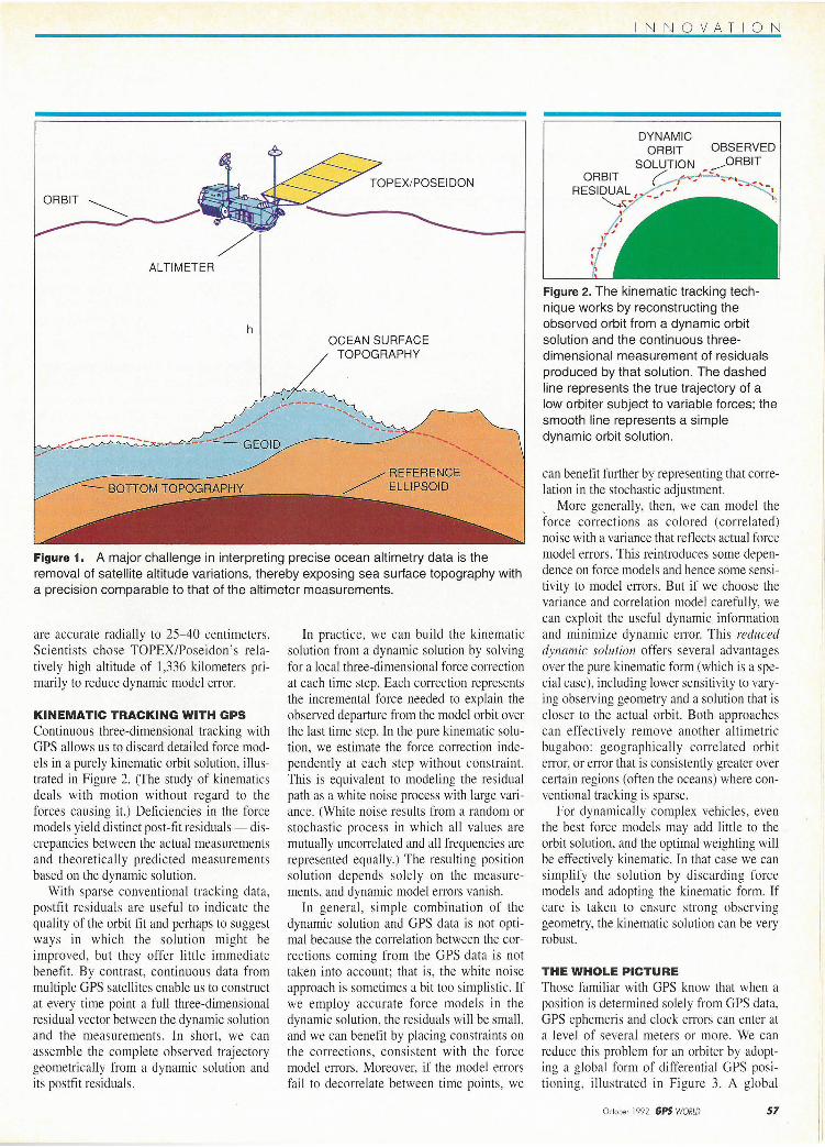
KINEMATIC TRACKING WITH GPS Continuous three-dimensional tracking with GPS allows us to discard detailed force models in a purely kinematic orbit solution, illustrated in Figure 2. (The study of kinematics deals with motion without regard to the forces causing it.) Deficiencies in the force models yield distinct post-fit residuals- discrepancies between the actual measurements and theoretically predicted measurements based on the dynamic solution.
With sparse conventional tracking data, postfit residuals are useful to indicate the quality of the orbit fit and perhaps to suggest ways in which the solution might be improved, but they offer little immediate benefit. By contrast, continuous data from multiple GPS satellites enable us to construct at every time point a full three-dimensional residual vector between the dynamic solution and the measurements. In short, we can assemble the complete observed trajectory geometrically from a dynamic solution and its postfit residuals.
In practice, we can build the kinematic solution from a dynamic solution by solving for a local three-dimensional force correction at each time step. Each correction represents the incremental force needed to explain the observed departure from the model orbit over the last time step. In the pure kinematic solution , we estimate the force correction independently at each step without constraint. This is equivalent to modeling the residual path as a white noise process with large variance. (White noise results from a random or stochastic process in which all values are mutually uncorrelated and all frequencies are represented equally.) The resulting position solution depends solely on the measurements, and dynamic model errors vanish.
In general , simple combination of the dynamic solution and GPS data is not optimal because the correlation between the corrections coming from the GPS data is not taken into account; that is, the white noise approach is sometimes a bit too simplistic. If we employ accurate force models in the dynamic solution, the residuals will be small, and we can benefit by placing constraints on the corrections, consistent with the force model errors. Moreover, if the model errors fail to decorrelate between time points, we
INN OVA TION
DYNAMIC ORBIT OBSERVED
N IT
Figure 2. The kinematic tracking technique works by reconstructing the observed orbit from a dynamic orbit solution and the continuous threedimensional measurement of residuals produced by that solution. The dashed line represents the true trajectory of a low orbiter subject to variable forces; the smooth line represents a simple dynamic orbit solution.
can benefit further by representing that correlation in the stochastic adjustment. , More generally, then , we can model the force corrections as colored (correlated) noise with a variance that reflects actual force model errors. This reintroduces some dependence on force models and hence some sensitivity to model errors. But if we choose the variance and correlation model carefully, we can exploit the useful dynamic information and minimize dynamic error. This reduced dynamic solution offers several advantages over the pure kinematic form (which is a special case), including lower sensitivity to varying observing geometry and a solution that is closer to the actual orbit. Both approaches can effectively remove another altimetric bugaboo: geographically correlated orbit error, or error that is consistently greater over certain regions (often the oceans) where conventional tracking is sparse.
For dynamically complex vehicles, even the best force models may add little to the orbit solution, and the optimal weighting will be effectively kinematic. In that case we can simplify the solution by discarding force models and adopting the kinematic form. If care is taken to ensure strong observing geometry, the kinematic solution can be very robust.
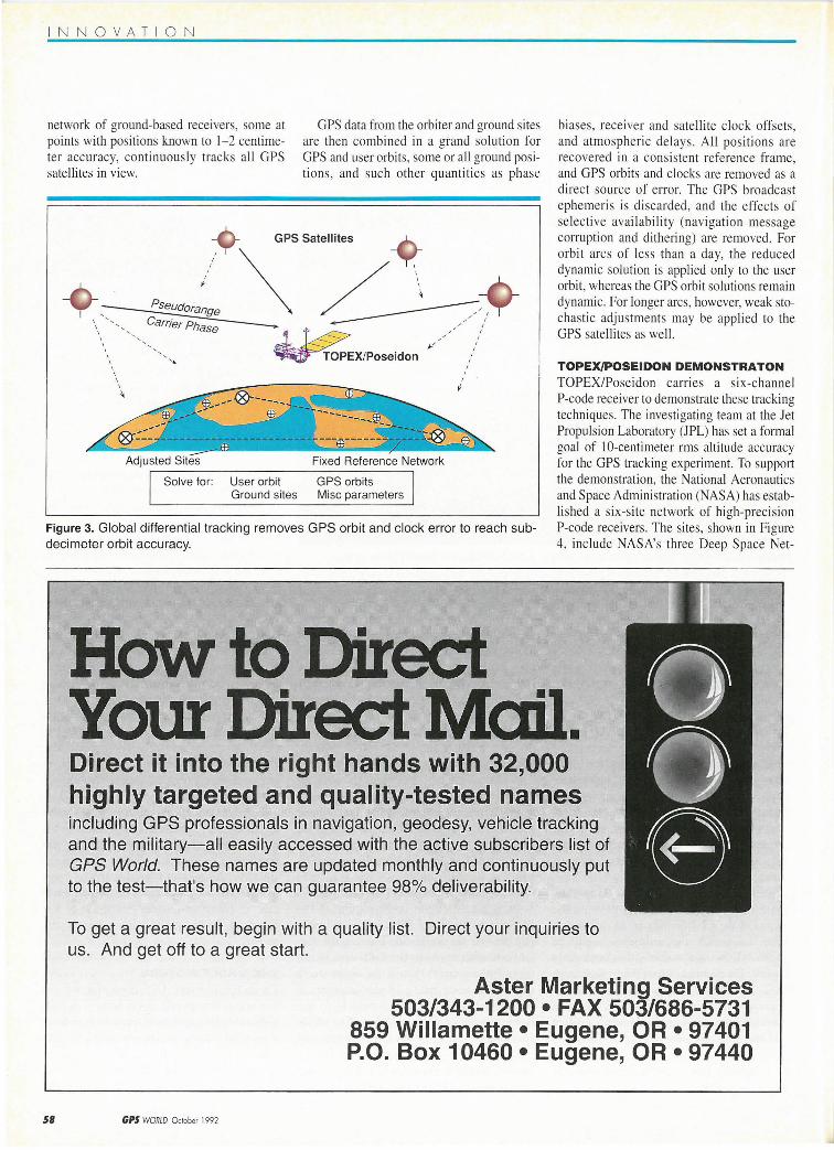
THE WHOLE PICTURE Those familiar with GPS know that when a position is determined solely from GPS data, GPS ephemeris and clock errors can enter at a level of several meters or more. We can reduce this problem for an orbiter by adopting a global form of differential GPS positioning, illustrated in Figure 3. A global
October 1992 GPS WORLD 57
INNOVATION
network of ground-based receivers, some at points with pos itions known to 1-2 centimeter accuracy, continuous ly tracks all GPS satellites in view.
GPS data from the orbiter and ground sites are then combined in a grand solution for GPS and user orbits, some or all ground positions, and such other quantities as phase
Fixed Reference Network
Solve for : User orbit GPS orbits Ground sites Mise parameters
Figure 3. Global differential tracking removes GPS orbit and clock error to reach subdecimeter orbit accuracy.
biases, receiver and satellite clock offsets, and atmospheric del ays. All positions are recovered in a consistent reference frame, and GPS orbits and clocks are removed as a direct source of error. The GPS broadcast ephemeris is discarded, and the effects of se lective availability (navigation message corruption and di thering) are removed. For orbit arcs of less than a day, the reduced dynam ic solution is applied only to the user orbit, whereas the GPS orbit solutions remain dynamic. For longer arcs, however, weak stochastic adjustments may be applied to the GPS satellites as well.
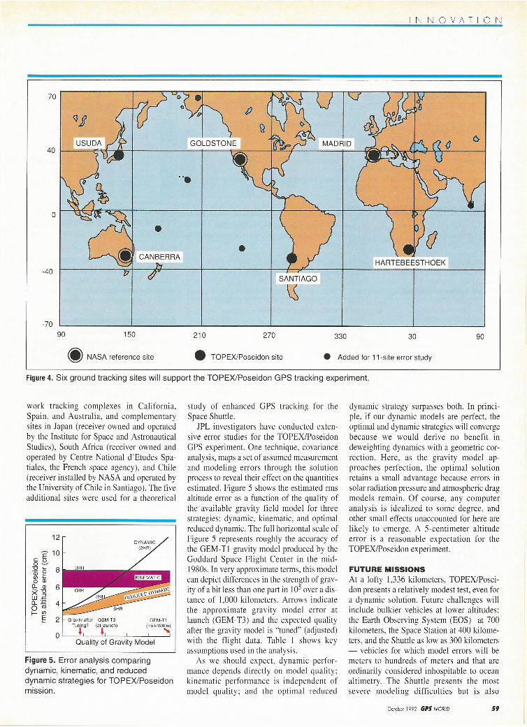
TOPEXJPOSEIDON DEMONSTRATON TOPEX/Poseidon carries a six-chan nel P-code receiver to demonstrate these tracking techniques. The investigating team at the Jet Propulsion Laboratory (JPL) has set a formal goal of I 0-centimeter rms altitude accuracy for the GPS tracking experiment. To support the demonstration, the National Aeronautics and Space Administration (NASA) has establi shed a six-site network of high-precision P-code receivers. The sites, shown in Figure 4, include NASA's three Deep Space Net-
' 1
How to Direct Your Direct Mail. 0
0 9
Direct it into the right hands with 32,000 highly targeted and quality-tested names including GPS professionals in navigation, geodesy, vehicle tracking and the military-all easily accessed with the active subscribers list of GPS World. These names are updated monthly and continuously put to the test-that's how we can guarantee 98% deliverability.
To get a great result, begin with a quality list. Direct your inquiries to us. And get off to a great start.
58 GPS WORW October 1992
Aster Marketing Services 503/343-1200 • FAX 503/686-5731
859 Willamette • Eugene, OR • 97401 P.O. Box 10460 • Eugene, OR • 97440
INNOVATION
70
40
0
-40 SANTIAGO
~
-70
90 150 210 270 330 30 90
~ NASA reference site • TOPEX/Poseidon site e Added for 11-site error study
Figure 4. Six ground tracking sites will support the TOPEX/Poseidon GPS tracking experiment.
work tracking complexes in California, Spain, and Australia, and complementary sites in Japan (receiver owned and operated by the Institute for Space and Astronautical Studies), South Africa (receiver owned and operated by Centre National d'Etudes Spatiales, the French space agency), and Chile (receiver installed by NASA and operated by the University of Chile in Santiago). The five additional sites were used for a theoretical
12
~ 10 c E 0~
~ e a (/) ~ 0 Ql
0... Ql 6 ><-g LlJ""' ~"'iii 4 I- (/)
E 2
Quality of Gravity Model
Figure 5. Error analysis comparing dynamic, kinematic, and reduced dynamic strategies for TOP EX/Poseidon mission .
study of enhanced GPS tracking for the Space Shuttle.
JPL investigators have conducted extensive error studies for the TOPEX/Poseidon GPS experiment. One technique, covariance analysis, maps a set of assumed measurement and modeling errors through the solution process to reveal their effect on the quantities estimated. Figure 5 shows the estimated rms altitude error as a function of the quality of the available gravity field model for three strategies: dynamic, kinematic, and optimal reduced dynamic. The full horizontal scale of Figure 5 represents roughly the accuracy of the GEM-Tl gravity model produced by the Goddard Space Flight Center in the midl980s. In very approximate terms, this model can depict differences in the strength of gravity of a bit less than one part in 105 over a distance of 1,000 kilometers. Arrows indicate the approximate gravity model error at launch (GEM-T3) and the expected quality after the gravity model is "tuned" (adjusted) with the flight data. Table 1 shows key assumptions used in the analysis.
As we should expect, dynamic performance depends directly on model quality; kinematic performance is independent of model quality ; and the optimal reduced
dynamic strategy surpasses both. In principle, if our dynamic models are perfect, the optimal and dynamic strategies will converge because we would derive no benefit in deweighting dynamics with a geometric correction. Here, as the gravity model approaches perfection, the optimal solution retains a small advantage because errors in solar radiation pressure and atmospheric drag models remain. Of course, any computer analysis is idealized to some degree, and other small effects unaccounted for here are likely to emerge. A 5-centimeter altitude error is a reasonable expectation for the TOPEX/Poseidon experiment.
FUTURE MISSIONS At a lofty 1,336 kilometers, TOPEX/Poseidon presents a relatively modest test, even for a dynamic solution. Future challenges will include bulkier vehicles at lower altitudes: the Earth Observing System (EOS) at 700 kilometers, the Space Station at 400 kilometers, and the Shuttle as low as 300 kilometers - vehicles for which model errors will be meters to hundreds of meters and that are ordinarily considered inhospitable to ocean altimetry. The Shuttle presents the most severe modeling difficulties but is also
Octobe r 1992 GPS WORLD 59
INNOVATION
Table 1. Assumptions for TOPEXJPoseidon error analysis
System Characteristics
Orbit (circular) 1 ,336 kilometers, 66° incl ination Number of ground sites 6 (with 3 NASA reference sites) Number of GPS satellites 18 Flight antenna field of view hemispherical Flight receiver tracking capacity 8 satell ites (L 1 & L2) Data types L 1 & L2 pseudorange/L 1 & L 2 carrier phase Data smoothing interval 5 minutes Smoothed data noise 5-centimeter pseudorange/5-centimeter carrier
phase
Adjusted parameters & a priori errors
TOPEX/Poseidon epoch state 1 kilometer; 1 meter/second each component GPS satellite states 2 meters; 0.2 millimeter/second each component Carrier-phase biases 10 kilometers GPS & receiver clock biases 3 milliseconds (modeled as white noise) Non-NASA ground locations 10 centimeters each component Zenith atmospheric delay error 10 centimeters (modeled as random walk)
Fixed errors evaluated
NASA reference positions 5 centimeters each component GM of earth uncertainty 1 part in 108
Atmospheric drag 10% Solar radiation pressure 10%
uniquely attractive as a host because it allows for short-term trials of "reflyable" instruments.
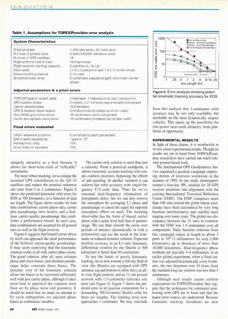
For more robust tracking, let us en large the assumed GPS constellation to the full 24 satellites and reduce the nominal reference site enw from 5 to 3 centimeters. Figure 6 shows the predicted kinematic orbit error for EOS at 700 kilometers, as a function of data arc length. The figure shows results for four data combinations: catTier phase only, carrier plus pseudorange (two levels), and a ficti tious carrier-quality pseudorange that establi shes a performance bound. In each case, data combinations are assumed for all ground sites as well as the flight receiver.
Figure 6 suggests that biased carrier phase by itself can approach the ideal performance of the fictitious carrier-quality pseudorange. It may seem surprising that the kinematic solution works at all with carrier phase alone. The grand solution, after all, must estimate phase and clock biases, and absolute pseudorange helps constrain those biases . The dynamic core of the kinematic so lution allows the biases to be recovered sufficiently well with just carrier phase, although it takes more time to approach the common error floor set by phase noise and geometry. lt should be noted that we made no attempt to fix cycle ambiguities; we adjusted phase biases as continuous variables.
60 GPS WORW October 1992
The carrier-only solution is more than just a curiosity. From a practical standpoint, it allows extremely accurate tracking with simple codeless receivers, bypassing the effects of anti-spoofing. In another variation it can achieve fair orbit accuracy with si ngle-frequency CIA-code data. Thus far we 've assumed dual-frequency elimination of ionospheric delay; but we can also remove the ionosphere by averaging Ll phase and pseudorange to cancel the equal but opposite ionosphere effect on each. The resulting observable has the form of biased carrier phase with a noise level half that of pseudorange. We can then smooth the noi se over periods of minutes (dynamically or with a polynomial) and use the result in the kinematic or reduced dynamic solution. Expected position accuracy in an L !-only kinematic differential solution for the Shuttle at 300 kilometers is better than 50 centimeters.
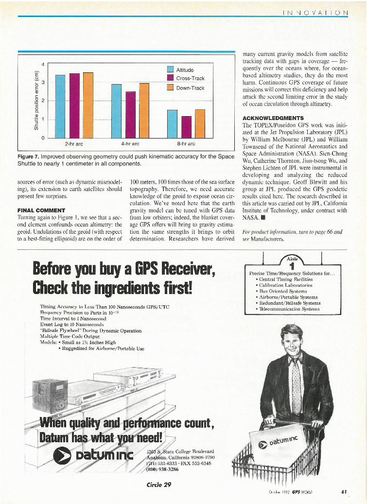
To test the limits of purely kinematic tracki ng, let us now assume a full-sky field of view (the Shuttles are equipped with GPS antennas top and bottom to allow this), an aUin-view flight receiver, and an 11-site ground network with 1.5-centimeter reference site error (see Figure 4). Figure 7 shows the predicted error in all position components for a demanding 300-kilometer Shuttle orbit for three arc lengths. The limiting error now approaches I centimeter. We may conclude
e m
Cii '6 ~ 10 Ul
E (f)
0 w 1
.1 .25
• Carrier Phase Only 8 Phase + 50-cm Pseudorange + Phase +S-cm Pseudorange D Carrier-Quality Pseudorange
.5 2 4 8 10 20 Arc Length (hr)
Figure 6. Error analysis showing potential kinematic tracking accuracy for EOS.
from thi s analysis that !-centimeter orbit accuracy may be not only reachable, but reachable on the most dynamically suspect vehicles. This opens up the possibility for low-power near-earth altimetry from platforms of opportunity.
EXPERIMENTAL RESULTS In light of these claims, it is worthwhile to review some experimental results . Though no results are yet in hand from TOPEX/Poseidon, researchers have carried out much relevant ground-based work.
The International GPS Geodynamics Service organized a geodetic campaign employing dozens of receivers worldwide in the summer of 1992. In one study, investigators rotated a four-day JPL solution for 28 GPS receiver positions into al ignment with the existing International Terrestrial Reference Frame (ITRF). The ITRF comprises more than 100 sites around the globe whose coordinates have been determined by very long baseline interferometry and satellite laser ranging over many years. The global rms discrepancy between the 21 sites in common with the ITRF was 1.5 centimeters over all components. Daily basellne solutions from this campaign repeat in length to about 3 parts in 109 (3 millimeters for each I ,000 kilometers) up to di stances of more than 10,000 kilometers. Dual-frequency phase residuals are typically 3-4 millimeters. In an earlier global experiment, when a fixed station was adjusted kinematically every 6 minutes, the rms departure over 24 hours from the standard long-arc solution was less than 3 centimeters.
Although such results cannot confirm expectations for TOPEX/Poseidon, they suggest that the techniques for centimeter positioning with GPS are in hand and that the major error sources are understood. Because kinematic tracking introduces no new
4
E' ()
";::'3 e (D c g 2 'iii 0 0. Q)
:;::o
5 .r:: (f)
D Altitude • Cross-Track
------------------------ ------------------------
0 Down-Track
2-hr arc 4-hr arc 8-hr arc
Figure 7. Improved observing geometry could push kinematic accuracy for the Space Shuttle to nearly 1 centimeter in all components.
sources of error (such as dynamic mismodeling), its extension to earth satellites should present few surprises.
FINAL COMMENT Turning again to Figure 1, we see that a second element confounds ocean altimetry: the geoid. Undulations of the geoid (with respect to a best-fitting ellipsoid) are on the order of
100 meters, 100 times those of the sea surface topography. Therefore, we need accurate knowledge of the geoid to expose ocean circulation. We've noted here that the earth gravity model can be tuned with GPS data from low orbiters; indeed, the blanket coverage GPS offers will bring to gravity estimation the same strengths it brings to orbit determination. Researchers have derived
Before you buy a GPS Receiver, Check the ingredients first!
Timing Accuracy to Less Than 100 Nanoseconds GPS/UTC Frequency Precision to Parts in 10- 12
Time Interval to 1 Nanosecond Event Log to 10 Nanoseconds "Failsafe Flywheel" During Dynamic Operation Multiple Time Code Output Models : • Small as 1% Inches High
• Ruggedized for Airborne/Portable Use
count,
College Boulevard L"Rnw•ema, California 92806-5790
533-6333 · FAX 533-6345 938-3286
Circle 29
INNOVATION
many current gravity models from satellite tracking data with gaps in coverage - frequently over the oceans where, for oceanbased altimetry studies, they do the most harm. Continuous GPS coverage of future missions will correct this deficiency and help attack the second limiting error in the study of ocean circulation through altimetry.
ACKNOWLEDGMENTS The TOPEX/Poseidon GPS work was initiated at the Jet Propulsion Laboratory (JPL) by William Melbourne (JPL) and William Townsend of the National Aeronautics and Space Administration (NASA). Sien-Chong Wu, Catherine Thornton, Jiun-tsong Wu, and Stephen Lichten of JPL were instrumental in developing and analyzing the reduced dynamic technique. Geoff Blewitt and his group at JPL produced the GPS geodetic results cited here. The research described in this article was carried out by JPL, California Institute of Technology, under contract with NASA . •
For product information, turn to page 66 and see Manufacturers.
1 1 Aisle
1 Precise Time/Frequency Solutions for . ..
• Central Timing Facilities • Calibration Laboratories • Bus Oriented Systems • Airborne/Portable Systems • Redundant/ Failsafe Systems • Thlecommunication Systems
October 1992 GPS WORlD 61