andrew seamone 2019 surf symposium 6 august 2019 reactor
TRANSCRIPT

Thermal-Hydraulics Feasibility for anUltra-Compact Nuclear Reactor Core
Andrew Seamone
2019 SURF Symposium6 August 2019
Reactor Operations and Engineering

Operation started in 1967 Split core
NBSR2

Wavelengths Energies Selectivity Magnetism Neutrality Capture
Why Neutron Research?3
10 m
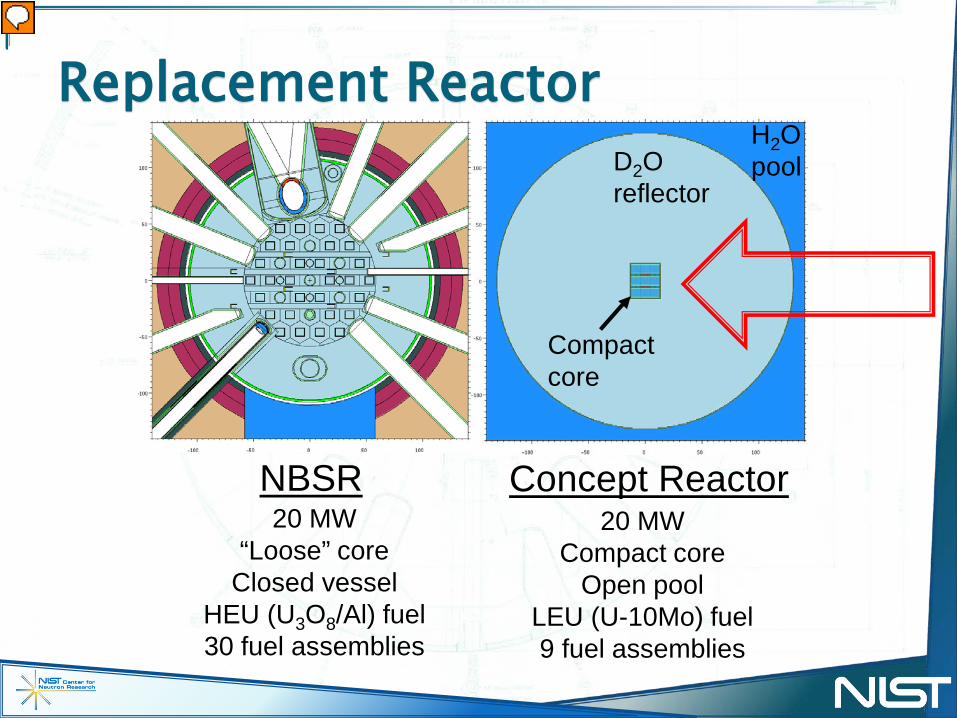
NBSR
D2O reflector
H2Opool
Concept Reactor
Compact core
20 MW“Loose” core
Closed vesselHEU (U3O8/Al) fuel30 fuel assemblies
20 MWCompact core
Open poolLEU (U-10Mo) fuel9 fuel assemblies
Replacement Reactor
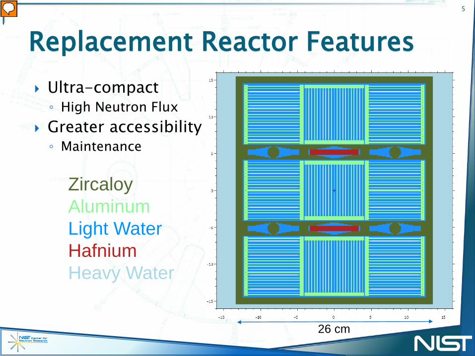
Ultra-compact◦ High Neutron Flux
Greater accessibility◦ Maintenance
Replacement Reactor Features5
ZircaloyAluminumLight WaterHafniumHeavy Water
26 cm

Reactor: FRM-II NIST concept OPAL
Cross-sectional plan view of reactor corePower (MW) 20 MW 20 MW 20 MWVolume 28 L 41 L 69 LPeak thermal neutron flux in reflector
8×10¹⁴
cm-2s-15.6×10¹⁴
cm-2s-14×1014
cm-2s-1
Motivation for Compact Reactor Core
6

Compact core geometries
Structural robustness◦ Larger forces acting on fuel elements
Cooling◦ High heat flux per fuel element
Replacement Reactor Challenges7

Structural Stability8
Miller velocity 2/3 of Millers velocity for
maximum actual flow Miller velocity design limit◦ High flow velocity can cause
fuel plates to deform
E – Youngs Modulus ρ – Coolant Densitya – Plate Thickness b – Wetted Widthh – Channel Width ν – Poisson’s RatioPlate deflection with increasing velocity
21 Fuel Plate Cross-Section
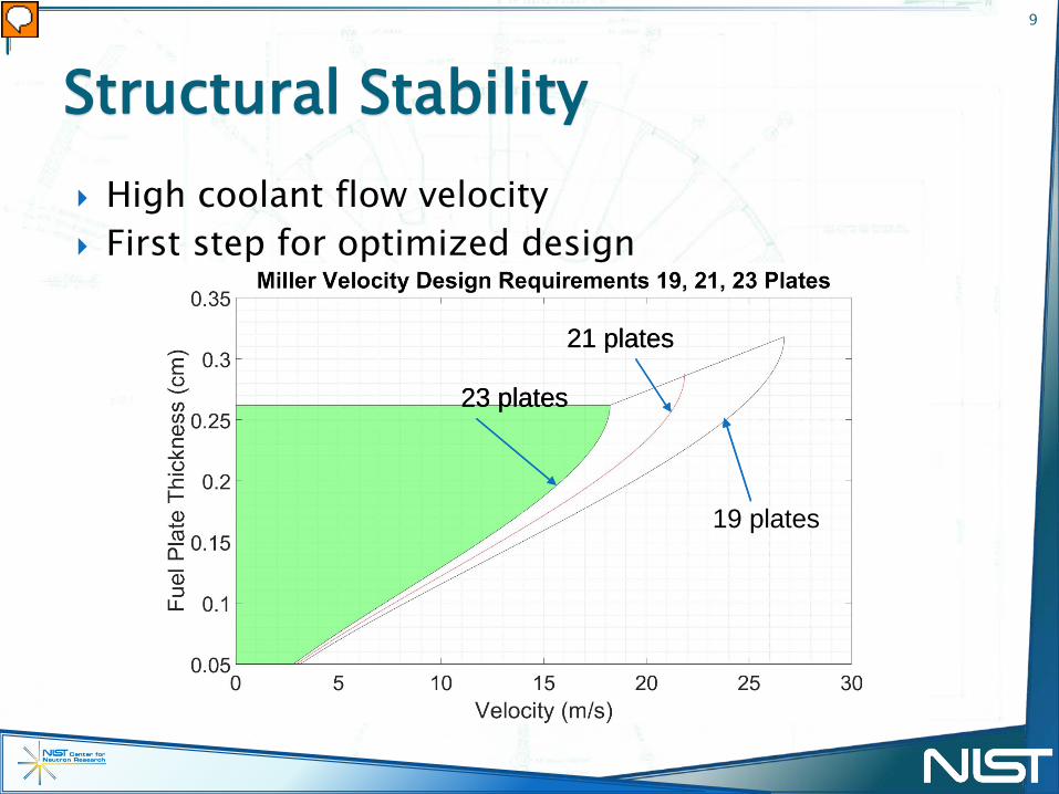
High coolant flow velocity First step for optimized design
Structural Stability9
23 plates
19 plates
21 plates
23 plates
21 plates

Curving the fuel plates offers more structural stability
Structural Stability10
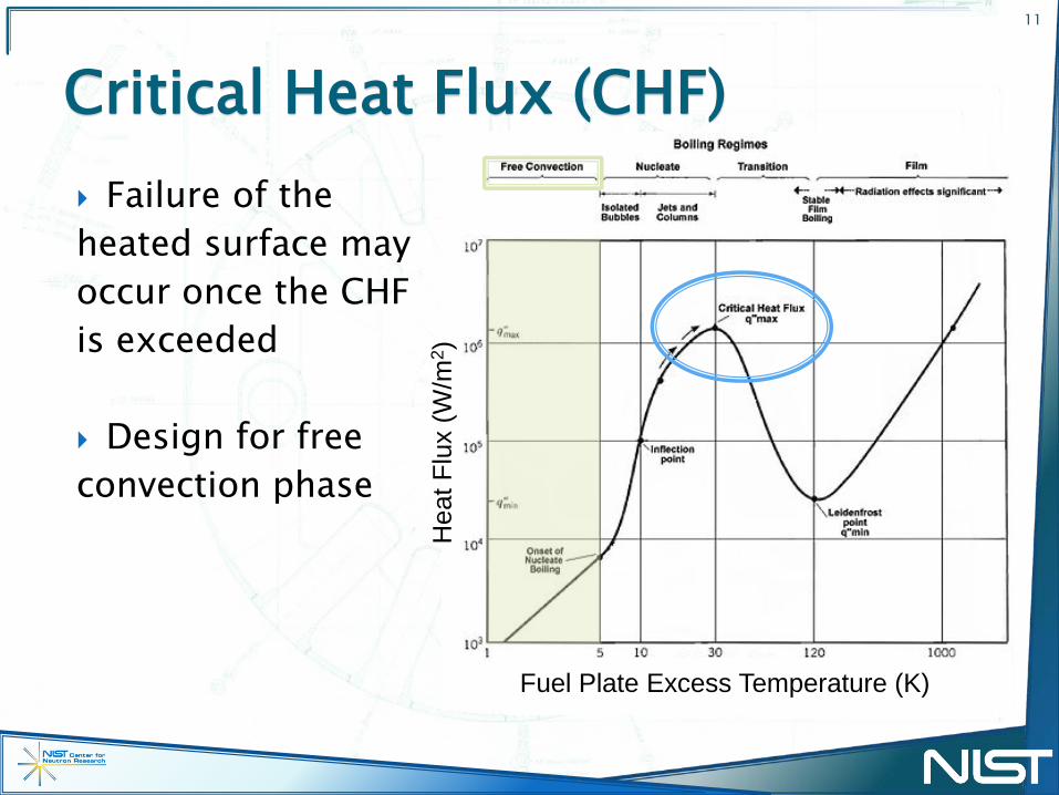
Failure of theheated surface mayoccur once the CHFis exceeded
Design for freeconvection phase
Critical Heat Flux (CHF)11
Fuel Plate Excess Temperature (K)
Hea
t Flu
x (W
/m2 )
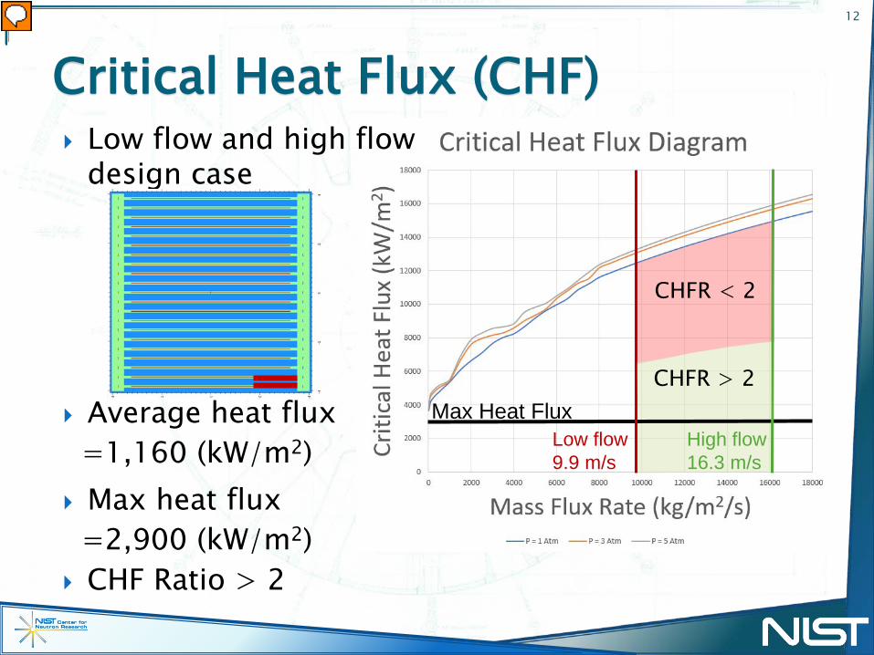
Low flow and high flow design case
Average heat flux=1,160 (kW/m2)
Critical Heat Flux (CHF)12
Low flow9.9 m/s
High flow 16.3 m/s
Max Heat Flux
CHFR < 2
CHFR > 2
Max heat flux=2,900 (kW/m2)
CHF Ratio > 2

Multiphysics solver◦ Computational fluid dynamics◦ Heat transfer◦ Nonisothermal flow
Evaluate◦ Pressure drop◦ Temperature increase◦ Change in flow velocity
COMSOL13

2D single element Temperature model
COMSOL Modeling14
Velocity (m/s) Temperature (C)
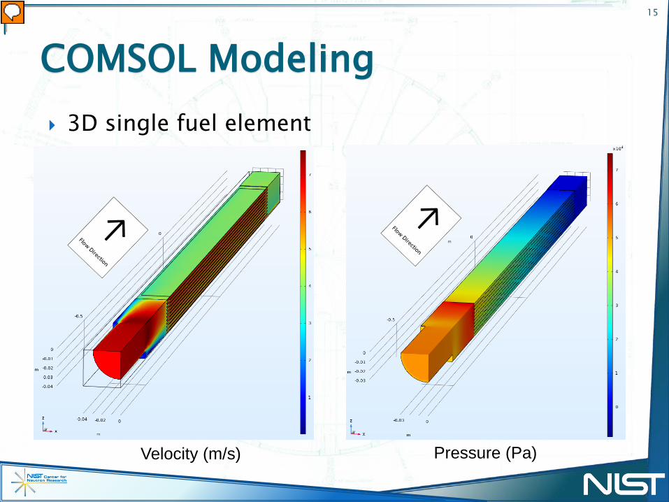
3D single fuel element
COMSOL Modeling15
Pressure (Pa)Velocity (m/s)
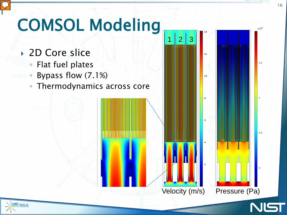
2D Core slice◦ Flat fuel plates◦ Bypass flow (7.1%)◦ Thermodynamics across core
COMSOL Modeling16
Pressure (Pa)Velocity (m/s)
1 2 3

COMSOL capabilities can extend to full reactor core Structural advantage with curved plates Critical heat flux and critical velocity are designed Greater neutron flux can be achieved
Conclusion17
Future Direction Run a full core simulation Virtual reactor Fluid structure interaction

Danyal Turkoglu Daniel Mattes Julie Borchers Joe Dura Reactor Operations and Engineering
Acknowledgements18

Mantecón, Javier González. Evaluation of mechanical stability of nuclear fuel plates under axial flow conditions. Diss. Universidade de São Paulo, 2019.
Miller, D.R. CRITICAL FLOW VELOCITIES FOR COLLAPSE OF REACTOR PARALLEL-PLATE FUEL ASSEMBLIES. United States: N. p., 1958.
Groeneveld, D.C. & Shan, Jianqiang & Vasić, A.Z. & Leung, Laurence & Durmayaz, A & Yang, Jun & Cheng, S.C. & Tanase, A. (2007). The 2006 CHF look-up table. Nuclear Engineering and Design. 2007.02.014.
Reference19
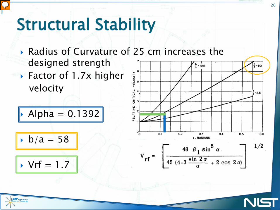
Radius of Curvature of 25 cm increases the designed strength
Factor of 1.7x highervelocity
Alpha = 0.1392
b/a = 58
Vrf = 1.7
Structural Stability20
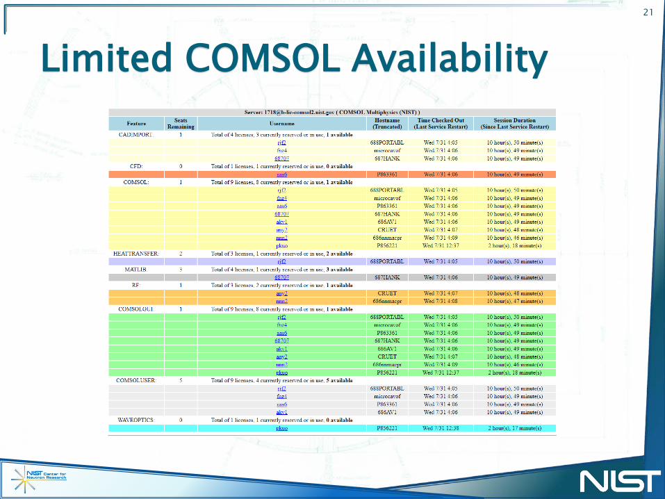
Limited COMSOL Availability21

Pathway to a new source
First began looking into a replacement reactor in 2013 Several concepts have been investigated in an effort to
optimize a reactor design for cold neutron science A succession plan that minimizes time between
operation of NBSR and the replacement reactor is ideal
22
NBSR operation?
Concepts Specifications
Design, Construction, Testing
NBSR-2 operation{Replacement
Reactor Project
??

LEU Fuel Assembly Design
23
NBSR Concept ReactorFoil thickness 0.0216 cm 0.0250 cmFoil width 6.134 cm 6.5 cmFoil height 27.94 cm 70 cmFoils per FA 34 (17×2) 21U-235 mass per FA 383 g 726 gFresh FAs per cycle 4 3Cycle length 38.5 d 50 d
Cd wires as burnable absorbers
Square profile(8.05 cm × 8.05 cm) allows rotations during refueling

Core design
24
Plan view (xy)
Cd wires as burnable absorbers
Hf shims (×6)
Zircaloy follower rods (×6)
Zircaloy chimney
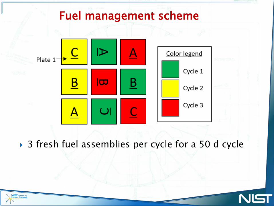
Fuel management scheme
25
3 fresh fuel assemblies per cycle for a 50 d cycle

Power distribution
26
Axial power profilesStripe PPFs at startup
Hot spot power peaking factor: 2.13◦ Maximum power density: 9.3 kW/cm3 × 2.13 = 19.8 kW/cm3
◦ Maximum heat flux: 116 kW/cm3 × 2.13 = 247 W/cm2
Heat flux exceeds NUREG-1313 limit for U3Si2 fuel

Fission density distribution
27
Plate #
Fission density versus plate number for discharged FA with highest burnup
Fission density (×1021
f/cm3)
Potential for high fission densities: 6×10²¹ fissions/cm3

Peak power density and fission density
28
NIST replacement reactor

Cold neutron source performance
29
High unperturbed thermal neutron flux in the reflector: 5.6×1014 cm-2 s-1
◦ More than a factor of 2 greater than NBSR Opportunity to optimize cold source designs and
locations for neutron science◦ Large gains (>2) in cold source brightness over NBSR are possible para-LH2 CNS
LD2 CNS
NBSR LD2 CNS
LD2 CNSpara-LH2 CNS Cold flux