and measurements a scientificpapersofthebureauofstandards iva.is...
TRANSCRIPT

AIRPLANE ANTENNA CONSTANTS1
By J. M. Cork
CONTENTSPage
I. Purpose 199II. Capacity and resistance measurements 199
1. Apparatus 199
2. Manipulation 200
3. Theory..... 201
4. Results 204
(a) Fixed antennas 204
(b) Trailing antennas 207
III. Directional effect 211
I. PURPOSE
The purpose of this work was to obtain general information
regarding the effective capacity, effective resistance, true capac-
ity, true inductance, and wave length, as well as the transmit-
ting directional effect of various types of airplane antennas.
In addition to trailing antennas of one, two, and four wires, the
constants of various fixed antennas were measured in an attempt
to find a satisfactory, substitute for the trailing wire at short
wave lengths.
II. CAPACITY AND RESISTANCE MEASUREMENTS
1. APPARATUS
All measurements were made in flight, using a continuous waveoscillator feeding directly into the antenna. A measurement of
the effective resistance and effective capacity of each antenna
was made at several different wave lengths, from which resistance
wave-length and capacity wave-length curves were drawn. Awiring diagram of the test set used is shown in Fig. 1 . It may be
observed that this is the familiar Colpitts circuit, in which the
antenna takes the place of the regular coupling condenser. Bychanging K
1from A to B a dummy antenna is substituted for the
1 The data given in thjs paper were obtained by the writer while an officer in the Signal Corps, United
States Army, and js published with the consent of this organization.
199

200 Scientific Papers of the Bureau of Standards {Vol. 15
one under test. This consisted of a calibrated straight wire
resistance variable in steps of o.i ohm, and a variable condenser
calibrated for both capacity and resistance at various wave lengths
and angular settings. The oscillator and dummy antenna, to-
gether with a wave meter of suitable range, were mounted on the
bakelite panel of a set box which fitted in the front of the cockpit,
convenient for reading condensers and ammeters. By switch
K2 the wave meter could be open circuited and thus absorb
no energy. All condensers were shielded by grounded copper
cases. For measurements at short wave lengths the inductance
was made by winding No. 14 wire on a wooden toroidal core,
having taps every three turns for various wave lengths. This
tOVo/ts.
^-^nyjqo^ Li-^
o o->
•—o 6 a—vAAaAaaAa-" A
> ° Dummy Antenna
Fig. 1.
—
Wiring diagram of airplane antenna test set
eliminated to a large degree all stray magnetic fields. Power was
supplied by a 10-volt storage battery and a 300-volt dynamotor,
battery driven. A lf A 2 , A 3are ammeters in filament, dynamotor,
and oscillating circuits, respectively. A grid leak of 50 000-
ohms shunted the variable grid condenser. All leads carrying
oscillations were made as short as possible to avoid stray capac-
ities.
2. MANIPULATION
The effective capacity was determined by adjusting the induc-
tance taps and grid condenser for good oscillation at approximately
the desired wave length, with the antenna in circuit, then setting
the wave meter at resonance. The switch K± is next turned to
Cork] Airplane Antenna Constants 20I
B and the dummy condenser adjusted until the wave meter is
again in resonance. From the condenser calibration the capacity
at this wave length may be obtained. To find the effective re-
sistance, having set capacities as above, the wave meter is open
circuited by opening K2 and the reading of A 2noted with K1 at A;
now turning Kxto B, R
2is adjusted until the A
2reading is dupli-
cated. From the calibration of R2
the effective resistance is
obtained. This furnishes a very accurate and sensitive means for
the determination of effective antenna resistance. By varying the
grid condenser the range of critical sensitivity may be set at any
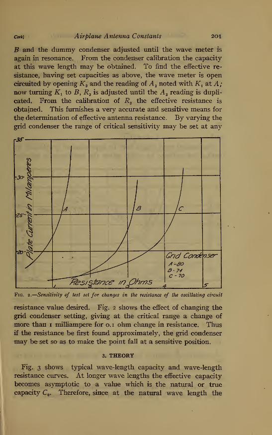
Fig. 2.
—
Sensitivity of test set for changes in the resistance of the oscillating circuit
resistance value desired. Fig. 2 shows the effect of changing the
grid condenser setting, giving at the critical range a change of
more than 1 milliampere for 0.1 ohm change in resistance. Thusif the resistance be first found approximately, the grid condenser
may be set so as to make the point fall at a sensitive position.
3. THEORY
Fig. 3 shows typical wave-length capacity and wave-length
resistance curves. At longer wave lengths the effective capacity
becomes asymptotic to a value which is the natural or true
capacity C . Therefore, since at the natural wave length the

202 Scientific Papers of the Bureau of Standards iva. is
total reactance of the antenna is zero (i. e., for an infinitesimal
applied voltage a large current flows in the antenna) , —~ effective
is zero. But the effective capacitance at all times equals the
difference between the natural capacitance and natural inductive
reactance, or
-^r effective =—, L uwt o)C
^0=^-^^)or,
and X = 2t^L CThe natural wave length may be approximated graphically by
noting the ordinate to which either the resistance or effective
Fig. 3.
—
Constants of a typical fixed airplane antenna
capacity curves are asymptotic; or, better still, since at wave
lengths above the fundamental the capacity reactance predomi-
nates, by plotting an effective capacitance wave-length curve as
shown in C, Fig. 3, practically a straight' line is obtained. This
may be extended to intersect the wave-length axis, thus giving
the natural wave length. Instead of the effective capacitance.
—-= effective,-^- effective may be used as well, since not actual re-coC C
actance values but only the intersection of the line with the axis
is desired.
The curve shown in B, Fig. 3, gives effective antenna resistance.
This, of course, is the resultant of several components. Fig. 4

Cork) Airplane Antenna Constants 203
shows the manner in which the components might be expected
theoretically to change with increasing wave length; b represents
the pure ohmic resistance due to the metallic conductors. Atlong wave lengths this is practically a constant, but increases
slightly at short wave lengths due to skin effect, shown by b 1.
If R 1 denotes the sum of the direct-current resistance R, plus the
Nf7p
£« ^v^
•e
•t>
*
<"~- £-.
6__——-
-
^^\. ^£~-
—
——~~"
^^d^ I4i?i<v Length
Fig. 4.—-Components of antenna resistance
additional resistance due to skin effect, at very short wave lengths
an approximate formula for the variation of R 1is
R'=R K_
But as X increases, the approximate formula 2 becomes
Curve c represents resistance due to dielectric loss. In this
respect an antenna like a condenser has a phase angle, and may
2 Fleming, Principles of Elec. Wave Telegraphy, p. 137.

204 Scientific Papers of the Bureau of Standards [Vol. i5
be considered as a resistance and a pure capacity in series, the
resistance increasing as the first power of the wave length. Thelocation of the dielectric producing the loss has been the subject
of considerable investigation. Dr. J. M. Miller 3 has shown that
the earth, as was commonly assumed, is rarely the cause, but
rather dielectrics in the proximity of the antenna. It is of inter-
est to observe that this effect was not noted in any of the airplane
measurements made.
Curve d represents any eddy current or hysteresis losses that
might occur. It would be difficult to separate these from the
radiation resistance, but they are perhaps both entirely negligible.
They would increase approximately with the frequency. Curve a
represents that part of the resistance due to electromagnetic
radiation. It is this factor which it is desirable to have as large
as possible. By considering a grounded antenna as one-half of a
Hertz oscillator, it has been shown that
i?a = l607T ( -r- ] ohms approximately.
Where h is the length of wire, X the wave length and a represents
the form factor or approximately the ratio of the average current
along the antenna length to the value at the base. For an antenna
2oscillating at its natural wave length this has the value -, but for
7T
a loaded antenna as is common in practice the current distribution
curve is practically a straight line and a = -. Then for an airplane
antenna of length, say, 200 feet, transmitting at a wave length of
400 meters, R& = 6 ohms approximately, and at 1000 meters
R* = 1 ohm approximately.
4. RESULTS
(a) Fixed Antennas.—Measurements were made upon fixed
antennas over a range in wave length from 60 to 160 meters. In
all cases the airplane wires bonded together were used as ground.
Fig. 5 shows some of the arrangements of wires measured.
Most of these were first measured close to the plane, then raised
on 2-foot and then 4-foot masts. The change from close to plane
to 2-foot mast produced a much larger decrease in natural capacity
than the change from 2 to 4 foot masts. The raise in height,
3 Bur. of Standards Scientific Paper No. 326.
m

Cork) Airplane Antenna Constants 205
however, is accompanied by an increase in radiation resistance.
Typical wave-length capacity and wave-length resistance curves
of the fixed antennas are shown in Fig. 3. This is for an antenna
All Tour Ft Masts
[FourFtMast
Fig. 5.
—
Types offixed airplans antennas
of the form D shown in Fig. 5 raised on masts 2 feet high. Theheight of mast used is determined by the maximum wind resistance
allowable, as well as by the electrical characteristics. Antenna116658°—19 2
2o6 Scientific Papers of the Bureau of Standards [Vol. i5
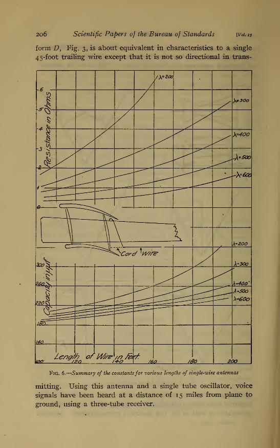
form D, Fig. 3, is about equivalent in characteristics to a single
45-foot trailing wire except that it is not so directional in trans-
FiQ. 6.
—
Summary of the constantsfor various lengths of single-wire antennas
mitting. Using this antenna and a single tube oscillator, voice
signals have been heard at a distance of 15 miles from plane to
ground, using a three-tube receiver.
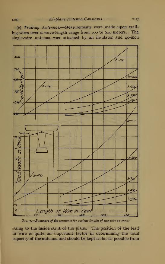
Cork) Airplane Antenna Constants 207
(b) Trailing Antennas.—Measurements were made upon trail-
ing wires over a wave-length range from 100 to 600 meters. The
single-wire antenna was attached by an insulator and 40-inch
-JOO-
X
1-340\3
//
y
A s/SO
h*20O
A- 'OO \*30ps
s^
/
/\=/SO
Cora
\ \^i )
//
vjw-
J /
\
//
(
/\=20O
¥**/OorV^/
—/ —
/
X40^x
££°2~
~o Len$ith r l/l///-ehareefU2 . ,
/p '<*o
Fig. 7.
—
Summary of the constantsfor -various lengths of two-wire antennas
string to the inside strut of the plane. The position of the lead
in wire is quite an important factor in determining the total
capacity of the antenna and should be kept as far as possible from

208 Scientific Papers of the Bureau of Standards [Vol. is
the wire network of the machine. Various lengths of wire were
thus used, and in Fig. 6 the results are summarized by plotting
capacity length of wire and resistance length of wire curves at
,>\=/7S-
<*X>„C\
A=200
*ty '
X=300
/
/-3SO -
\~400
\=SOO
<
y^r i
kTOPU>^L
)
( \
\H^Cr~C——^r:
'^T7S-
h=200
8V'
\-30Q
1' \-400
\-UX>
1-p<
so s~<{£2?Jft £fM/t66 7 ?4- rt? 6te 66 ft
Fig» 8.
—
Summary of the constantsfor various lengths offour-wire antennas
various wave lengths. Thus the characteristics for any wire
length may be obtained by taking the ordinates of the various
wave-length curves at that abscissa. Fig. 7 shows a like sum-
Cork) Airplane Antenna Constants 209
mary for a two-wire antenna attached as shown in the figure,
using the wires in parallel against airplane wires as ground.
Data were also obtained using one wire as the ground and the
-4so—
fbur ^400
Two ^
5-JOO ^-
-
-1One ^sj
,
•
Two \
3 $four N
\ \
r <2/7^ \s„
s^
-/ /s'u
—
,
,
/o \
ler* <%.>o Si. 10
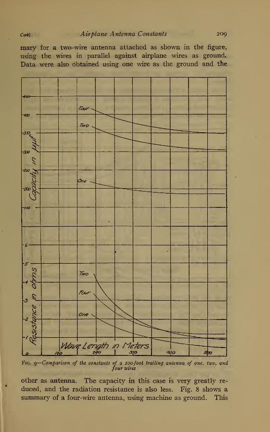
Fig. 9
—
Comparison of the constants of a 100-foot trailing antenna of one, two, andfour wires
other as antenna. The capacity in this case is very greatly re-
duced, and the radiation resistance is also less. Fig. 8 shows a
summary of a four-wire antenna, using machine as ground. This

2IO Scientific Papers of the Bureau of Standards [Vol. 15
antenna has a very large capacity, as would be expected. Fig 9shows a comparison of the characteristics of a 100-foot single,
two, and four wire antenna. The resistance could in no case be
observed to increase at longer wave lengths due to dielectric
losses.
The effect of the same antenna on different planes was also
tried. Fig. 10 shows a typical trailing wire antenna on A 3 a
DeHaviland plane, A 2 sl Curtiss training plane, A ± a Curtiss plane
with a fine network of wires in wings placed there to improve the
Fig. 10.
—
A comparison of the constants of the same antenna on different types of airplanes
plane for radio purposes. While the capacity of A x was larger
than A 2 , its radiation resistance appeared less and results in-
dicated that the unmetallized plane should actually be a better
transmitter than A v While the final demonstration of this was
interrupted, preliminary results with actual sets in use seemed to
indicate it.
The capacity values mentioned herewith are perhaps accurate
to within 10 micro-microfarads, as repeat tests did not differ by
this amount. .The resistance values, however, may be in error
by 20 per cent, especially at the longer wave-length values.

Cork) Airplane Antenna Constants
III. DIRECTIONAL EFFECT
211
In order to determine the directional transmitting effect of
the various antennas, a receiving set, as shown in Fig. n, wasconnected to a symmetrical vertical wire antenna. The receiv-
ing set consisted of a detector tube with grid at positive potential
and a three-stage audio-amplifier with tubes having a negative
grid potential. In the plate circuit of the last tube was placed
the primary circuit of a transformer with secondary connected
to the heater of a thermocouple. The output emf of the thermo-
couple was connected to a sensitive Paul microammeter. Then
s Amplifier
Fig. ii.—Wiring diagram of receiving set
with a modulated undamped transmitter the plane flew over a
marked distant point in the different directions of the compass.
When directly over the point the operator shut off the trans-
mitter, and at the receiving station the microammeter reading
just before dropping to zero was recorded.
As it would be very difficult to compute mathematically the
exact relation between microammeter reading and receivea
energy, since it would necessitate knowing just where on its
characteristic curve each tube was being worked, the following
test was made. The current in the transmitting antenna was set
at various known values, as i\ and I2} and the corresponding
micro-ammeter readings, C\ and C2taken, wave length and direc-
tion remaining the same ; the constants should remain almost the

212 Scientific Papers of the Bureau of Standards [Vol. 15
same if the amplitude of the incoming wave did not vary greatly.
Thus, assume
—
and,
I2=KC«
then
^Jogl 1
-\ogl2
log Cx- log C2
This means then that if the microammeter readings are to be
proportional to transmitted currents, they must be raised to the
a power, or, if proportional to energy to the 2 a power.
Fig. 12.
—
Directional effect of a two trailing wire airplane antenna
Making this correction in the data, the trailing wire antenna is
found to be quite directional, giving about twice the radiation in
the direction of motion that it does in the reverse direction, as

Cork) Airplane Antenna Constants 213
shown by Fig. 12. The fixed antennas are not decidedly direc-
tional.
The directional effect is probably a function of the relation
between the antenna length and the wave length. A theoretical
explanation of this effect is quite difficult. The electrostatic
component of the electromagnetic field at a distance r from a
radiator having a length component perpendicular to r of h sin a
and a current of IQis
4
_ _, h sin a IEx= 2 t V 2
—=- where V2 =3 x io10
and the magnetic component at right angles and in the same phase
h sin a I nMt= 2 7T
r
From these equations currents parallel with the antenna wire
should have no effect upon the energy received at points directly
in line with the wire, forward or backward. This energy must,
then, be due to radiation from.perpendicular currents. It may
be, however, that the inclination of the antenna with the horizon-
tal line of flight presents a perpendicular radiating component to
a point forward, which would be less or entirely lacking to a point
in the rear. In general, any explanation of the directive effect of
the Marconi bent antenna when used over sea water would apply
to the airplane antenna.
This opportunity is taken to express thanks to A. A. Oswald, of
the Western Electric Co., for valuable suggestions given, and to
those officers and enlisted men of the Signal Corps by whose
authority and assistance this work was made possible.
Washington, February 21, 191 9.
* J. Zeaneck, Wireless Telegraphy, p. 35; Feb. 21, 1919.