and low-pressure casings introduction the turbine casing is - yimg
TRANSCRIPT

5-1
5
Mechanical Design Considerations for High- and Low-Pressure Casings
Introduction
The turbine casing is essentially a cylindrical vessel and the main stationary portion of
each expansion section. This casing encloses the rotating elements of the unit and at the same
time locates the stationary blades, either directly, or through the location and support of an inner
casing, which itself carries the stationary blades and/or diaphragms. The principle components of
the casing are the shells, which provide the mechanical strength of the element and carry and
locate other elements such as packing heads, diaphragms, and the inner casing or blade carriers.
The casing is normally split along its horizontal joint at the centerline to facilitate
assembly and provide access to the rotor and internal stationary portions of the unit. The shell
halves are normally connected through a bolted flange at their horizontal joint and act to contain
the working fluid while maintaining it in intimate contact with the steam path blade elements.
Casings may also provide locations for internal packings or portions of the steam seal
system and could, if moisture is present in the steam, be equipped with internal moisture
collection and drainage systems. The high-pressure shells should also, in the case of minor
failures, be capable of containing missiles that are generated from the rotor.
Both the upper and lower portions of the casings can be arranged to provide connections
for welded pipe stubs. To these stubs are connected external pipes that allow steam to be
extracted for regenerative feed heating or other cycle or process uses. Such steam is extracted
from the main steam flow. The casing may also be penetrated by other pipes that are used to
introduce or extract steam for other parts of the cycle. It is normal for pipe connections to the
upper half to be connected through flanges or other device that allows their quick disassemble at
outages and then reconnection without the use of any form of heating or metal fusion techniques.

5-2
Special provisions in the casing are necessary to admit the high-pressure, high-
temperature steam and make provision for the differential expansion that occurs between the
various portions of the shells. Such differential expansion occurs because of the different
temperatures or temperature gradient along the axial length of the casing and also because of the
different rates at which the various parts of the unit heat and cool with main steam temperature
changes. For double-shell construction, it is necessary for the main inlet pipes to pass through the
outer casing and introduce steam to the main steam inlet belt or nozzle box.
The high-pressure casings are normally supported at each end through arms that are
produced integral with and extend from the casing to pedestals that are located adjacent to, and
between, the casings or sections. Transverse and/or axial keys are used to maintain alignment of
the shells at these pedestals. Such keys have normally been hardened by nitriding and are located
on the bottom vertical centerline to ensure correct alignment is maintained at all loads and during
transient operating conditions.
Low-pressure casings are designed to contain the steam and to minimize the in leakage of
air when the exhaust pressure is sub-atmospheric. Because at exhaust from the turbine the
volumetric flow is large, it is normal for these low-pressures elements to be produced by
fabrication, and because such fabrications are not structurally strong, it becomes necessary to
support them for their entire perimeter at their horizontal joint or a similar location below this
joint.
Components Comprising the Turbine Casing
The turbine casings have a number of individual elements, which when assembled allow
the unit to operate safely and to achieve high levels of reliability and efficiency. A list of the
principle components follows.

5-3
The shells. The shells are the main structural components that are produced by casting,
fabrication, or in some designs by a combination of both depending upon the experience and
preference of the designer.
The shaft-end packing head. The packing head is attached to the shells, and carries the
gland rings that are located where the rotor passes through the shells. These heads are designed
to carry gland rings that minimize the outward leakage of the steam or the inward leakage of air.
The inlet section. The inlet to the steam path must be designed to allow free access of the
inlet pipes, transport the steam to the nozzle box, and minimize leakage of steam at those
locations. The inlet is designed to permit movement between the inlet pipes and the main body of
the shells.
The explosion diaphragm on low-pressure sections. In the low-pressure shells there is
a need to provide for the rapid removal of steam from the internals of the casing in the event
there is a sudden and high rate of pressure increase due to some transient condition.
A diffuser section at exhaust from the last stage. In an effort to maximize the energy
extracted from the working fluid, the final rotating blade is arranged to exhaust into a diffuser
section normally produced as part of the casing fabrication.
Functions of the Shells or Casings
The casings are the main containment vessel of the turbine, which defines their major
function of containing the working fluid. These elements, therefore, surround the steam path and
can be made to perform several other secondary functions. These functions are dependent upon
the steam conditions within the steam path, which conditions influence the arrangement,
materials, and support for these casings.
It is necessary to consider casings in two separate categories, arranged most suitably by
the temperature of the steam they contain. The high-pressure/temperature elements are those that

5-4
operate with steam temperatures above the range of about 700 degrees Fahrenheit (°F), and the
low-pressure/temperature elements are those that operate at temperatures below this value.
The high-pressure/high-temperature sections
The steam admitted to these high duty casings will have pressures up to 3500 pounds per
square inch absolute (psia) although units have been designed to 5000 psia. Temperatures are at
the 1000 to 1100°F value at the inlet and can be reheated to 1000 to 1050°F before readmission
to the intermediate pressure section. However, units have been designed to operate at higher
values of temperature.
Because of the initial steam conditions, the high-pressure/high-temperature casings are
subjected to high internal pressure, which produces significant tangential, longitudinal, and radial
stresses in the walls. These casings must therefore be designed so they are able to withstand
these conditions at normal operating conditions and during transients. It must also be recognized
that at the higher temperatures, the mechanical properties of the material from which the casing
is produced are lowered, which reduces the factors of safety of these major components.
The reheat casings are subject to lower steam pressures, but because of the increase in
specific volume of the steam at these lower pressures and the high reheat temperatures, these
casings can be subject to stresses of the same magnitude as exist in the high-pressure sections.
In addition to being a containment pressure vessel, the shells have certain secondary functions.
Fulfillment of these functions is important to the production of a successful design and is
necessary for the operation of the unit. The most important of these follow.
• The outer shells of high- and intermediate-pressure sections are part of the main
external structure. As such they must have sufficient strength they are able to transmit
the large differential expansion forces through the casing arms to slide the pedestals
on their sole plates. This they must do without any form of vertical or lateral

5-5
distortion that would affect the alignment of the steam path. The sole plates must be
able to be moved by the casing in such a manner they will not cause deflection,
excessive distortion, or misalignment. Alignment of the turbine generator must be
maintained at all times, under all loads and variations of steam conditions, and in all
directions.
• The casings must also be able to carry the loads developed on the stationary blade
rows (individual blades and diaphragms) and inner casing due the pressure deferential
within the steam path.
• The shells should have sufficient strength and weight that the casing is able to resist,
without change of alignment, external forces and moments imposed on it by station
piping. (Tavernelli and Coffin 1961) Figure 5–1 shows how various forces may be
imposed on the casing by expanding piping thrusts that tend to lift the casing from its
foundations and could be sufficient to cause misalignment.
Fig. 5–1 The Piping Thrusts Developed on a Casing
• The shells must maintain the stationary elements they carry in correct axial and radial
alignment relative to the rotor. That is, concentricity must be maintained together
with axial alignment.
• The outer shells must be sufficiently rigid that they are able to transmit and withstand
external forces due to excessive vibrations, including earthquakes and other high
intensity natural phenomena. These phenomena, although rare and highly unlikely in
most North American installations, could have catastrophic consequences if their
severity were sufficient to cause sudden and excessive misalignment within a casing
with the rotor at operating speed.

5-6
• The mass of the casings must be sufficient to make significant contributions toward
holding the unit firmly on its foundations and suppressing vibrations.
• In the event of a blade, wheel, or rotor failure, the inner and outer shells of the high-
and intermediate-pressure casings provide a strong containment vessel for the rotating
parts. These shells should be capable of absorbing high impact projectiles, thereby
minimizing the possibility of a projectile penetrating the casing and causing serious
injury to plant personnel.
• The outer shell provides a barrier by which heat is retained within the unit. This
barrier is reinforced by thermal lagging, which is attached to the outer surfaces of the
shell, and is the main barrier to radiant heat loss. The inner casing also provides a heat
barrier which reduces heat loss by minimizing temperatures on the inner surface of
the outer shell.
• Turbine shells are massive structures. They are thick sectioned, and due to their mass,
respond slowly to changes in steam temperature. This thermal inertia to the rate of
temperature change, gives rise to the need for special considerations of stationary to
rotating element clearances. The shell design must be adequate to accommodate this
thermal lethargy at all points of contact with potentially lower temperature elements,
such as valves, bearing housings, and the front standard.
• The thermal gradient developed in the casing walls will introduce thermal stresses
during operation. This is particularly so during temperature transients, when stresses
can be high.
The design of the shells should be such that the stresses induced provide a unit in which
the predicted life of the components is acceptable. To do this the material properties must be
carefully defined, and the design must eliminate, to the greatest extent possible, stress

5-7
concentration regions. This will help minimize the possibility of thermal or low-cycle fatigue
cracking.
The high-pressure, high-temperature casings are normally cast components. However,
fabricated elements have been used in some nuclear applications where the initial or nuclear
boiler delivery pressures are not more than about 1000 psia. Such nuclear casings do, however,
have free moisture in them that introduces another type of problem.
The low-pressure/low-temperature sections
The low-pressure or exhaust sections of a turbine unit are normally designed to accept
steam at an inlet pressure of about 200 psia and a maximum temperature of about 700°F. This
maximum temperature is set more by the material of the rotor than of the casings.
The normal design practice is to make the total expansion ahead of the low-pressure
portion of the unit occur in one or more sections. At the lower pressure end of the high-pressure
casing, pressures may be at the 400 to 600psia level and temperatures in the 700 to 600°F range.
At exhaust from the intermediate or reheat section, the pressure will normally be in the range 70
to 200 psia and the temperature at the 550 to 700°F level.
The normal arrangement of the low-pressure expansion sections of a high-output unit is
to have multiple double-flow sections, with an inner and an outer casing in which the axial thrust
is canceled. In these designs, the casings at their inlet are subject to a pressure differential across
their walls equal to the differential between the inlet pressure and atmosphere. There and also
many units in service with three low-pressure expansions—one accepting one-third of the steam
exhausting from the reheat or intermediate pressure section, and the other two-thirds going to a
double-flow low-pressure section.
The low-pressure casings have many of the same functions and characteristics as the
high-pressure, high-temperature components. However, due to their physical size and the fact

5-8
they are vessels required to maintain an internal pressure that is higher than atmospheric pressure
within the inner sections and a vacuum in their hood and between the inner an outer sections,
these requirements are modified. The basic functions of the low-pressure casing are:
• the outer shell must locate from the foundations and support the inner shell with
sufficient rigidity that it can maintain alignment of the steam path under all conditions
of transient load and steam conditions
• the inner casing must be able to carry and support the low-pressure diaphragms, to
maintain concentricity and axial alignment under all steam conditions and under both
steady state and transient loads.
• the casings must act as a transition and diverting structure to direct the steam
exhausting from the last stage blades to the condenser, minimizing the frictional loss
within the hood
• the low-pressure section casings must incorporate a seal system that limits the ingress
of air into the system and thereby help maintain vacuum integrity
• the casings must be sufficiently that robust they will not deflect by unacceptable
amounts due to vacuum pull during operation. Similarly the casing must be able to
resist vertical deflection due to heavy water loads in the condenser hot well.
• the casing, while mounted on the condenser with either rigid or flexible connections
and supported off the foundation, must have sufficient axial flexibility it is able to
accommodate temperature swings within the system and maintain alignment
• The casing must be designed with sufficient axial clearance to accommodate thermal
differential expansion at normal operating conditions and under short and long rotor
conditions
• The casings must be designed so steam extraction pockets can be used to remove
steam from the casings for regenerative feed heating

5-9
The high and reheat casings can normally be expected to contain any blades that detach
as missiles. In addition these cast steel casings should also contain the rotor, although the unit
would be wrecked. Such high condition casings therefore act as a containment vessel or safety
barrier in the case of a significant accident or material rupture. The low-pressure casing may
contain the blades, although last stage blade elements can cause significant damage if they
detach from the rotor. If a rotor or wheel bursts in the low-pressure casing, it is most unlikely the
casing will be able to contain the missiles that are generated.
High-Pressure/High-temperature Casings
There are a number of casing configurations that fall within the category of high-
pressure/high-temperature application. These include the following.
High-pressure sections for fossil application. These units are normally subject to a
maximum cycle condition of 3500 psia and 1000°F. Although pressures up to 5000 psia and
1200°F have been used on advanced cycles. These casings are always built to the configuration
of an inner and an outer shell so that a pressure, and more importantly, a temperature gradient
can be established across both the inner and outer components.
Intermediate-pressure sections for fossil application. There are still in operation
turbine units that do not utilize reheat at exhaust from the high-pressure section. Therefore, there
are turbine casings that are intended to operate on steam having conditions equal to those
exhausting from the high-pressure section. Such units were used when the cost of fossil fuel was
inexpensive at the time the plant was built and are often used where a plant is located near the
fuel source. The intermediate pressure sections are probably the least stressed type, which can be
called high-pressure/high-temperature, and which will be encountered in modern power plants.
5-10
Reheat pressure sections. It is normal in modern power plants to reheat the steam after it
has completed its initial expansion in the high-pressure section. Therefore, the steam entering the
intermediate pressure section casings has a pressure about 7 to 10% lower than the steam
exhausting from the high-pressure section, and the temperature of reheat is about 1000°F.
There are designs in which the high and reheat expansions are contained within a single
shell. In these designs the steam, after its initial (high-pressure) expansion, is returned to the
boiler reheat section, reheated, and returned to the same shell for a second expansion.
Second reheat sections. Some cycles are designed to utilize a second reheat section. In
this cycle the steam, after expanding in the first reheat section, is returned to the boiler where it is
given a second reheat and again returned to the turbine to continue its expansion in a second
lower pressure reheat section. Upon return from the boiler second reheat section, the steam has
had its temperature again raised to a value close to the initial temperature and is returned to this
second reheat section with a pressure reduced by 7 to 10% from that exhausting from the first
reheat section.
Those two turbine sections discussed previously are defined as the first and second reheat
sections and in certain applications are arranged for double flow.
High-pressure sections for nuclear application. With the advent of water-cooled
reactors producing low-quality steam, a high-pressure section was required that was capable of
handling large volumetric flows of steam that contained a small initial moisture content.
Therefore, as steam enters the turbine, it has an initial pressure of about 1000 psia and can have
an initial moisture content of 0.25%. In such casings, provision must be made to collect and
drain a considerable amount of water that will be deposited on the casings and other internal
parts of the unit as the pressure decays.
These turbine sections, in order to be able to accommodate the high volumetric flows
without exceeding axial velocity limitations for efficient expansion of the steam, have tended to

5-11
be used at 1800 revolutions per minute (rpm) for 60 Hertz (Hz) applications. While the majority
of 50 Hz application is as 1500 rpm, there are some 3000 rpm applications at lower ratings. The
need to go to half speed units has caused an increase in rotor and casing diameters to maintain an
acceptable velocity ratio _. This has tended to increase the stress levels in the casings because of
the larger diameter required of the casings.
The casings for fossil application discussed here normally contain a high speed
rotor—3000 or 3600 rpm—driving a two-pole generator. Because of its high speed of rotation
coupled with high operating temperatures, there are physical limitations to the diameter that can
be specified for the rotor. Currently, it is difficult to produce a rotor forging with suitable
material properties and capable of carrying the rotating blades much larger than 40 inches (in.).
Also the maximum length of blades must be limited because of the centrifugal loading.
Therefore, the maximum casing internal diameter would be limited to about 65 to 70 in.
In nuclear high-pressure sections and some fossil sections, particularly for cross
compound units, the sections can be arranged to drive half speed 1500 rpm or 1800 rpm four-
pole generators. Because of their lower speed, it is possible to increase the rotor diameter without
exceeding stress limitations in the rotor or blades. With this type of rotor, a limitation of
approximately 64 in., producing a total rotor diameter of about 95 in. exists.
These diametral limitations are for 60 Hz units. For 50 Hz units, the possible diameters
would be somewhat larger. However, the maximum diameter is often a function of rotor
manufacturing capability rather than stress levels. As manufacturing techniques improve, it is
possible larger diameter rotor forgings will be available and larger casings required.
Pressure Staging and Multiple Shells
The casings contain the high-pressure, high-temperature steam with a differential from
working condition to atmospheric. The duty on the individual casing shells is normally reduced

5-12
by the use of a double casing construction. This form of construction provides for a
temperature/pressure barrier to be established with conditions from high-pressure inlet to high-
pressure exhaust across an inner shell,and then from high-pressure exhaust to atmospheric over
an outer.
Shown as Figure 5–2 is a two-casing arrangement, in which the individual diaphragms, or
stationary blades, are located and carried in the inner shell. This inner shell is then supported
from flanges machined into the outer surface of the inner shell. These locate in special locating
grooves machined into the inner surface of the outer shell. It can also be seen from Figure 5–2
that there is a constant pressure and thermal gradient across the outer shell, and the inner shell is
subjected to a gradient dependent upon the differences between the stage conditions and the
high-pressure exhaust surrounding the inner shell.
Fig. 5–2 A Double Casing Unit With the Diaphragms Carried in Inner Casings or Blade
Carriers
Figure 5–3 is a casing design with the high- and reheat-pressure sections are contained
within a single casing. With this arrangement the high-pressure expansion has an inner casing to
carry the diaphragms, and the outer casing is subject to the same pressure gradients as seen in the
casing design of Figure 5–2. After reheating, the steam is returned to the reheat section, which is
a single casing design, with the diaphragms carried in grooves machined into the inner surface of
the shell. Therefore, this shell is subject to a decreasing gradient along its length from stage
conditions to atmospheric.
Fig. 5–3 A Combined High-Pressure and Reheat Section

5-13
For the lower-pressure/high-temperature shells, such as used for intermediate or reheat
sections, the major concern is with thermal gradients. In this type of section it is possible to make
the casing walls thinner and more flexible. A casing of this design is shown in Figure 5–4.
(Hummer and Drahy 1964) With this type of design, steam is introduced from the inlet pipe into
the inner casing. This unit has seals at a to prevent the excess leakage of steam while allowing
for the expansion and contraction of the inlet pipes. This allowance is provided to accommodate
pipe movement during start-up and shutdown, or whenever the inlet pipes will heat and cool
much faster than the surrounding casing.
Fig. 5–4 An Intermediate (Reheat) Section, With Inner Walls and Extraction Pockets for
Pressurizing the Outer Casing
The steam enters the nozzle box then expands through the steam path. At completion of
its expansion, steam at the high-pressure exhaust condition surrounds the accessible portion of
the inner casing, which is then subject to pressure and temperature gradients corresponding to the
difference between individual stage and section exhaust conditions. The outer shell is subject to
pressure and temperature differentials equal to the high-pressure exhaust conditions and local
ambient. Had this casing been of single-shell construction, the single outer casing would have
been subject to the total differential between stage and ambient conditions.
In this type of design, it can be seen that diaphragms are supported and carried in inner
casing rings with each supporting a number of stages. These are also termed blade carriers.
These diaphragm groups provide for access regions where steam can be removed from the unit
for regenerative feed heating. In these extraction belts or pockets, the steam exists at the stage
discharge conditions from the upstream carrier, making the outer casing inner surface conditions

5-14
equivalent to the extraction conditions. This reduces the temperature and pressure gradient across
the casing walls.
An alternate arrangement of the high-pressure casing is to eliminate the inner shell after
the high-pressure expansion is partially complete. When this is done the direction of the flow is
reversed, led to the other side of the nozzle box where the expansion is completed. Shown as
Figure 1–38 of chapter 1 is such a design with the flow reversed after eight stages to flow
through a final three before being returned to the boiler reheater section. With this design, the
steam path is split into two portions, an upper pressure portion and a lower pressure portion. The
arrangement of the shaft-end seals is the same except the pressure range across them will differ.
The only significant difference in such a design is that the outer casing will be subject to
a higher pressure and temperature differential over the first portion of the expansion. The second
or reversed portion has eliminated the inner portion of the casing, and the diaphragms are carried
by the single casing.
The reversal point—end of expansion portion—is selected based on three considerations.
These are:
1. the need to extract steam from the section for regenerative feed heating
2. the need to lower the temperature and pressure gradients across the individual casing
portions
3. the adjustment of the axial thrust developed in the two blade portions. These two
portions of thrusts are opposed, and will affect the thrust which needs to be carried by
the thrust block.
Reversal point selection affects shell pressure, temperature, and axial thrust. These effects
are best reviewed from the high-pressure expansion line of Figure 5–5 that shows that steam
enters the section at conditions Pin and Tin. The individual stage points of the high-pressure
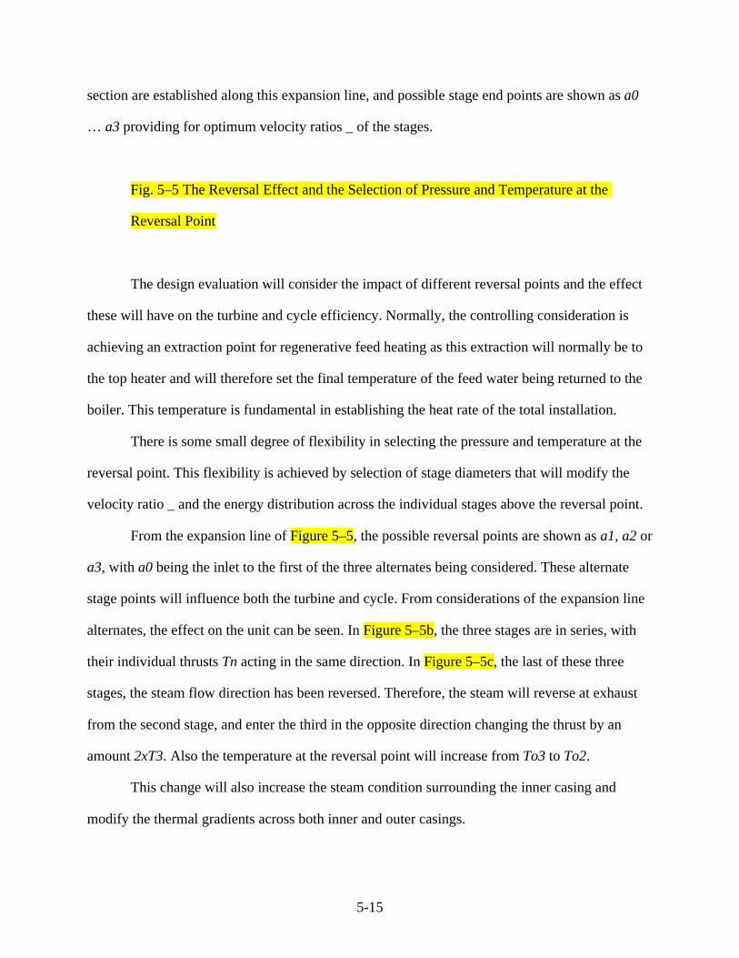
5-15
section are established along this expansion line, and possible stage end points are shown as a0
… a3 providing for optimum velocity ratios _ of the stages.
Fig. 5–5 The Reversal Effect and the Selection of Pressure and Temperature at the
Reversal Point
The design evaluation will consider the impact of different reversal points and the effect
these will have on the turbine and cycle efficiency. Normally, the controlling consideration is
achieving an extraction point for regenerative feed heating as this extraction will normally be to
the top heater and will therefore set the final temperature of the feed water being returned to the
boiler. This temperature is fundamental in establishing the heat rate of the total installation.
There is some small degree of flexibility in selecting the pressure and temperature at the
reversal point. This flexibility is achieved by selection of stage diameters that will modify the
velocity ratio _ and the energy distribution across the individual stages above the reversal point.
From the expansion line of Figure 5–5, the possible reversal points are shown as a1, a2 or
a3, with a0 being the inlet to the first of the three alternates being considered. These alternate
stage points will influence both the turbine and cycle. From considerations of the expansion line
alternates, the effect on the unit can be seen. In Figure 5–5b, the three stages are in series, with
their individual thrusts Tn acting in the same direction. In Figure 5–5c, the last of these three
stages, the steam flow direction has been reversed. Therefore, the steam will reverse at exhaust
from the second stage, and enter the third in the opposite direction changing the thrust by an
amount 2xT3. Also the temperature at the reversal point will increase from To3 to To2.
This change will also increase the steam condition surrounding the inner casing and
modify the thermal gradients across both inner and outer casings.
5-16
The modern design many manufacturers utilize contains a nozzle box as shown in Figure
5–2 and in Figure 1–38 of chapter 1. These nozzle boxes are self-contained vessels, located
within but forming part of the inner casing. These boxes are normally produced by forging and
are designed to distribute the steam around a portion of the inlet annulus and discharge it through
the first stage nozzle plates as seen in chapter 6. In the case of the nozzle box, the highest steam
conditions sensed by the casing are those of the steam discharging from these first stage nozzles.
The total casing arrangement in a self-contained nozzle box is essentially that of a triple-
shell construction. Nozzle boxes are now used in practically all designs with an initial pressure
above 2000 psia and temperatures above 900°F. Depending upon the duty intended for the unit
and the system into which it will be electrically connected, the first stage nozzles may be
grouped in the following manner.
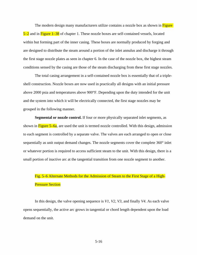
Segmental or nozzle control. If four or more physically separated inlet segments, as
shown in Figure 5–6a, are used the unit is termed nozzle controlled. With this design, admission
to each segment is controlled by a separate valve. The valves are each arranged to open or close
sequentially as unit output demand changes. The nozzle segments cover the complete 360° inlet
or whatever portion is required to access sufficient steam to the unit. With this design, there is a
small portion of inactive arc at the tangential transition from one nozzle segment to another.
Fig. 5–6 Alternate Methods for the Admission of Steam to the First Stage of a High-
Pressure Section
In this design, the valve opening sequence is V1, V2, V3, and finally V4. As each valve
opens sequentially, the active arc grows in tangential or chord length dependent upon the load
demand on the unit.
5-17
Two 180° arcs. A similar design employs two 180° segments, Figure 5–6b, with the joint
between the inlet arcs at the horizontal joint. In this arrangement, the inlet arcs may be fed by
one- or two-control valve arrangements. Again there are small inactive arcs, which in this design
are located at the horizontal joints.
As with the design shown in Figure 5–6a, steam is admitted to independent arcs, each
covering a nominal 180° of the tangential position. Up to 50% load steam is admitted to the top
half only with valves V1 and V2 open. Past 50% the other valves open to full load.
Full arc admission. One 360° segment or inlet arc is seen in Figure 5–6c. This
arrangement is similar to Figure 5–6b except there is a flow connection from the upper to the
lower chambers. This flow connection may be in the steam chest downstream of the control
valves but is more commonly made in a header adjacent to the control valves. Steam flow to this
common chamber is controlled by valves that admit steam to the entire inlet arc.
With this design the valves will open sequentially in response to load demands, but each
of the valves V1, V2, V3, and V4 feeds the complete 360° arc. This is termed throttle control.
There will normally be a small inactive arc at the horizontal joint. However, the effect of this on
the stimulus produced can be reduced by careful design of the joint partitions.
The Low-Pressure Casings
The term low-pressure/low temperature, in terms of turbine section arrangement is
applied to those expansion that accept incoming steam from a higher pressure section, and allow
it to expand to exhaust or condenser pressure. The casings that enclose this energy level steam
path tend, in modern units to be a separate, often double-flow section.
However, in many older and lower rating units without steam reheat, the lower steam
condition expansion occurred in a casing that was integral with the inlet or higher condition

5-18
casing at the inlet portion of the expansion. Often these casings are built using a cast high-
pressure section with a fabricated low-pressure section.
The older design single-casing units were produced by both casting and fabrication. In
many designs, the high-pressure section was produced from a steel casting and the lower
pressure portion was a fabricated structure bolted at a vertical joint to the high-pressure section.
This joint will often have a seal weld around its outer diameter to prevent the flow of air into or
steam out of the steam path.
The low-pressure casing is designed to accept steam from the exhaust of the expansion
immediately above it in terms of system pressure and temperature. The conditions of the steam
admitted to low-pressure casing are typically as follows.
In a fossil cycle. In these cycles the steam derives from the high, intermediate, or reheat
sections. Such steam is normally superheated. Its pressure is generally in the range of 70 to 200
psia. The initial temperature can be as high as 800°F. However, there are often limits placed on
this temperature not by considerations of the casing but rather by the operating temperature the
low-pressure rotor material can tolerate.
In a water-cooled nuclear cycle. In these cycles, the steam is admitted from the
intermediate system of the unit. Such an intermediate system will comprise a moisture separator
and possibly a reheater. Therefore, the steam conditions are typically in the range 70 to 250 psia,
and the temperature in the non-reheat cycle is at the saturation temperature corresponding to the
steam inlet pressure. In the case of the nuclear reheat cycle, steam is raised to a temperature less
than the initial cycle steam pressure saturation temperature by an amount equal to the terminal
temperature difference of the live steam reheater.
The steam at entry to the nuclear non-reheat, low-pressure section can contain moisture,
and the quantity is a function of the effectiveness of the moisture separator. For this reason, it is
probable the low-pressure, non-reheat cycle will have moisture present throughout the

5-19
expansion, and the casing must be designed to accommodate this moisture existing at high-
pressure levels and possibly having high velocities.
In an effort to maximize cycle efficiency and extract as much energy from the expanding
steam as effectively as possible, the exhaust pressure from the low-pressure section is passed to a
condenser that produces sub-atmospheric pressures in the low-pressure exhaust hood. The
condenser is normally optimized, designed, and selected to produce an exhaust pressure between
0.5 and 6.0 in. of mercury absolute (Hga) at all loads and with all cooling water temperatures.
As the exhaust pressure decreases there is an increase in the volumetric flow in the
discharge section of the L-0 blade system and casing. To minimize the frictional losses
associated with the resulting high-velocity flow of steam in the exhaust, the casing is normally
mounted directly above or adjacent and connected to the condensers. These exhaust casings can
also contain deflector plates designed to direct the steam into the condenser and distribute the
flow as evenly as possible over the entire flow down area.
The large volumetric flows associated with large modern units often requires multi-flow
exhausts be used so sufficient blade annulus area is available and the steam exhaust velocity is
limited to acceptable values.
Shown in Figure 5–7 is a double-flow low-pressure section with a monoblock rotor. From
this figure, it can be seen this section comprises a double-flow casing with five rows in each
flow. Both the inner and outer sections are fabricated. In this design the inner section is designed
to carry and support blade rings or diaphragms that are produced by the methods described in
chapter 6. The pockets used for the extraction of feed heating steam can also be seen.
Fig. 5–7 A Double-flow Low-Pressure Section
5-20
The inner shell is designed to locate the stationary blade rows and hold them in a correct
spatial position relative to the rotating blade rows. The stationary blade carrier elements or rings
are produced as outer diaphragm webs that carry one or more stationary blade rows. These outer
blade-ring carriers or webs locate directly in grooves machined into the inner casing fabrication
and permit adjustment within the inner casing to achieve optimum steam path alignment. These
fabrications also allow for space to remove steam for regenerative feed heating.
In the upper half of the low-pressure casings there are pressure relief or explosion
diaphragms. These diaphragms are designed to rupture and relieve any pressure that exceeds
atmospheric. Therefore, if for some operational or other reason vacuum is lost and the pressure
inside the low-pressure hood increases to a value above an acceptable limit, then the reversal of
pressure will deflect the diaphragms out and cause them to rupture. Rupture of the explosion
diaphragms will release the inner pressure of the casing, allowing the steam to escape from the
unit into the power-house or atmosphere in the case of an outside unit. The diaphragm rupture
pressure is normally between 15 and 30 psia. Rupture of these diaphragms will automatically
shut down the unit. If pressure were allowed to build up in the exhaust hood, levels of pressure
and temperature would increase to levels that would destroy the blade system.
Low-Pressure Casing Arrangement
The large number of multiple exhausts required for modern condensing units is
conveniently achieved by arranging for two or more double-flow sections in parallel. To achieve
a suitable temperature increase rate in the feed heating system and because of the large energy
range in low-pressure sections, three or four extraction of steam for regenerative feed heating are
normally required from the low-pressure expansions. Such an extraction requirement means that
the low-pressure hoods be produced so steam can be removed at a number of stage points in each

5-21
expansion. This requirement can complicate the general arrangement, and for some designs,
demands steam path and hood variation from one flow to the other.
If steam flow quantities are such that a single-flow section does not provide sufficient
discharge area, it is normal to arrange the low-pressure portion of the unit to employ a single or
multiple double-flow low-pressure sections. It was common at one time to employ designs with
three exhaust flows, with the one single expansion connected to the intermediate or reheat
pressure section discharge. This concept is not used extensively in the majority of modern units,
as it is more cost effective to develop modular designs of double-flow units, with specific
arrangements for steam extraction. These modular low-pressure designs also permit a better
mechanical arrangement of the low-pressure sections.
It is, therefore, becoming less common to employ an arrangement of three exhaust flows.
There are, however, still in successful operation a number units in which a single-flow low-
pressure section is connected directly to the intermediate section. This intermediate-
pressure/low-pressure (IP/LP) section can then be used with a single double-flow section to
provide a three-flow arrangement. In the three-flow arrangement, the first stationary blade row of
the low-pressure sections is set so that steam admitted to each of the three flows is controlled so
that with possible different steam extractions patterns in each. The exhaust flow from each
expansion last-stage blade row is the same.
The pressure range across the low-pressure sections is small when compared to the high
and reheat sections at one-fifteenth to one tenth their range. However, the energy extracted from
the low-pressure section can produce an output comparable to the sum of the output from the
other two expansions. Because of its large physical size and the fact that the space between the
outer hood and inner casing is maintained at vacuum pressure, there is a large downward force
resulting from the pressure differential between the inner hood and atmospheric. This total
pressure is sufficient to deflect the total casing vertically downward.

5-22
The low-pressure casing is, because of its size and the fact that it is not a massively rigid
structure like the cast high and intermediate or reheat sections, deflected downward. The extent
of this downward deflection is sensitive to the vacuum produced by the condenser. There can
also be a change in casing elevation as the level of water in the condenser hot well changes.
Older designs are still in use in which the total expansion from inlet condition to
condenser exhaust is achieved in a single casing. Shown as Figure 5–8 is the cross section of
such a unit, in which the casing is produced in sections that are bolted together to form a single
expansion. The low-pressure casing can be manufactured by either casting or fabrication. A seal
weld between the low-pressure and high-pressure casings may also be used. This casing is
designed to provide for the extraction of steam for regenerative feed heating and has a valve
chest produced integral with the high-pressure inlet.
Fig. 5–8 A Single Flow Unit With the Low-Pressure Casing Attached Directly to the
High-Pressure Section
Since the steam exhausting from the low-pressure section flows to the condenser, it is
convenient and economical to mount the low-pressure section above and connected directly to it.
While flexible connections exist, it is also convenient to weld the lower half casing to the
condenser shell to form a continuous structure.
The bearings supporting the low-pressure rotor can be constructed and supported in one
of two ways. These bearings are produced either with the bearing shells as an integral part of the
low-pressure fabrication or they are mounted external to the casing supported off the foundation.
There are two aspects of these two possible design alternates that should be considered and
evaluated.
5-23
1. When mounted from a pedestal on the foundation, the rotor elevation does not
change with vacuum or condenser hot well water quantity. It then becomes relatively
easy to predict the deflected shape and alignment requirements of the rotating
portion of the unit. However, because the casing will deflect downward under these
influences and must carry the stationary portion of the steam path, including the
sealing arrangement at the shaft end and diaphragms, there could be a need to
increase the radial clearance of the sealing systems in the low-pressure section to
allow for the difference in vertical deflection between the two sets of steam path
components.
2. When supported from the low-pressure fabrication, the radial seals at both the shaft-
end positions and the stationary blades can be maintained at or near optimum values
because the rotor will rise and fall with the bearings. This will minimizes leakage
losses. However, because the rotor will rise and fall as the vacuum changes, the
designer must have data on predicted deflection amounts to be able to establish the
normal running deflected form of the rotor.
With the bearings located within the exhaust hood, the rotor will have a shorter span,
limiting the bending stress induced in it.
Low-Pressure Casing Structures
The physical size of many low-pressure casings, particularly for 1500 and 1800 rpm
applications, are so large the casing must be constructed in several sections using vertical joints
in addition to the necessary horizontal joint split.
The two-casing (inner and outer) design of units consists of several portions, and these
should be considered separately because there are significant differences between them. These
casing segments are described next.

5-24
The outer upper shell
For the small exhaust-stage blade designs, it is possible to produce the entire upper
fabrication as a single structure. For large exhaust blade systems, the upper shell may consist of
two or more fabrications with these sections joined by bolted connection at the centerline. It is
necessary to break the structure into sections because of the shipping and handling restrictions.
There can also, in the largest fabrication, be limitations imposed by the size of machine
tools required to produce the components and the furnace size needed to complete any stress
relief requirements after welding.
The main structural components of an upper outer casing are shown in Figure 5–9. The
basic shell consists of a wrapper plate that provides the upper outer casing, and there may be
connections to this wrapper from the crossover pipe for steam admission. There will, in addition,
normally be provision for explosion diaphragms. The end walls are normally flat and must
provide sufficient distance from the exhaust or discharge line of the blades to the end walls. If
this space is not sufficient, there will be an unacceptable loss of the steam kinetic energy upon
impact with the walls causing an energy loss within the hood (see chapter 3). The wrapper will
require the use of reinforcing ribs and struts within the hood to provide strength against both
distortion and the downward atmospheric deflection.
Fig. 5–9 An Upper Outer Fabricated Casing
Design considerations for the upper hood require the wrapper and end walls be
sufficiently thick to resist deflection and distortion and be suitable for the vacuum pull. The outer
hood should also be designed so the bearings and steam seal components can be accessed
5-25
without the need to remove the outer casing. There will also be provision for access ports, so the
unit can be entered without the removal of the hood.
It is a normal design process to make a vibration analysis of the exhaust hood and then
use the reinforcing ribs and struts to de-tune the fabrication away from coincidence with any
natural frequencies developed within the structure.
The outer lower shell
The outer lower shell is the primary support structure carrying the low-pressure turbine
section. It must be capable of withstanding the vacuum load on both the side and end walls and
the vertical downward thrust transmitted to it by the upper half casing though the horizontal
joint. This structure must, if the low-pressure bearing is an integral part of the fabrication, carry
the bearings and support the weight of the rotor. The total downward thrust due to vacuum load
and weight must be carried through the casing while maintaining adequate bearing alignment.
The total low-pressure load is transmitted from the casing to the foundation by the support
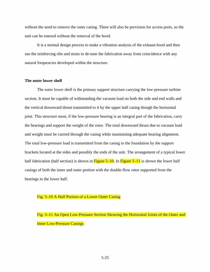
brackets located at the sides and possibly the ends of the unit. The arrangement of a typical lower
half fabrication (half section) is shown in Figure 5–10. In Figure 5–11 is shown the lower half
casings of both the inner and outer portion with the double-flow rotor supported from the
bearings in the lower half.
Fig. 5–10 A Half Portion of a Lower Outer Casing
Fig. 5–11 An Open Low-Pressure Section Showing the Horizontal Joints of the Outer and
Inner Low-Pressure Casings

5-26
The outer lower shell is fabricated from carbon steel plates, and the shell is given rigidity
by the use of internal struts. These can be seen in Figure 5–12. A primary design consideration of
the lower half outer shell is its need to support and provide location to the inner casing and
possibly bearing cones. It is also important that it can maintain radial and axial alignment during
both normal and transient operation.
Fig. 5–12 A Lower Half Inner Casing Seen From Above the Horizontal Joint
The inner casing
The inner casing carries and supports the low-pressure section stationary blades and/or
diaphragms. These casings, in a double-flow configuration, contain at their center an inlet bowl
that accepts the incoming steam from the crossover/around pipes and directs it into the first stage
stationary blade row around the complete 360° flow annulus. The inner casing also contains
extraction steam belts that collect the feed heating steam from the main steam flow required for
regenerative feed heating. These belts extend around the complete blade outer circumference and
are connected to a pipe transporting the steam to the heaters.
In some designs, the lowest pressure heaters are located within the condenser body, but
the steam must still be transported from the extraction belt to the heater shell. Because the low-
pressure section will have moisture in several stages, there is also provision made in the inner
casing to collect centrifuged moisture or to locate the diaphragms that have provision for this
moisture collection. In this case, the low-pressure casing provides the drains that remove the
collected moisture. The lower half of an inner casing is shown in Figure 5–12, where the
fabricated arrangement can be seen.
This inner casing is normally a separate structure supported from the outer casing.
However, for older smaller rated units with a lower inlet temperature, it is possible to

5-27
manufacture the inner shell as an integral part of the outer. But for higher inlet temperatures, it is
necessary to manufacture the inner shell as a separate structure to accommodate the excessive
thermal gradients and differentials that can develop across the walls. In these older, lower rated
units with a lower inlet temperature, the single casing fulfills the requirements of the inner
casing. Also, it is connected directly to the condenser and therefore subject to the transient
thermal and load conditions normally experienced by the outer. These casings can be subjected
to high loading but the designer will allow sufficient margin that stress levels are well within
acceptable limits.
The inner shells are essentially open-ended, cylindrical pressure vessels with admitted
steam expanding axially in both directions in the double-flow configuration. In double-flow
designs, steam is admitted into an inner cylindrical annulus where it divides to flow axially out
through the steam path and exhausting to the condenser. Because the two flows are essentially
symmetrical, the axial thrust developed on the casing is also symmetrical and balanced. The
thrust developed in the tangential direction is in the same direction on both flows and therefore
additive. The casing must be keyed at its connection points to the other portions of the
foundation to ensure these thrusts are constrained. Relative to the weight of the structure these
thrusts are small, but there is normally some provision for containing them, particularly within
the individual blade rows.
The steam is admitted to the double-flow casing through one or two openings on top of,
at the bottom, or on the sides of the casing. The numbers and locations of these openings are
determined by the steam volumetric flow rate and conditions. The number of crossover/around
pipes, and their sizing is chosen so the mean steam velocity in the pipes and inlet annulus is not
greatly in excess of 150 feet per second (ft/sec).
Steam for feed heating is extracted from the inner casing at points immediately after the
rotating blade row. A circumferential opening into which the steam can flow is arranged around
5-28
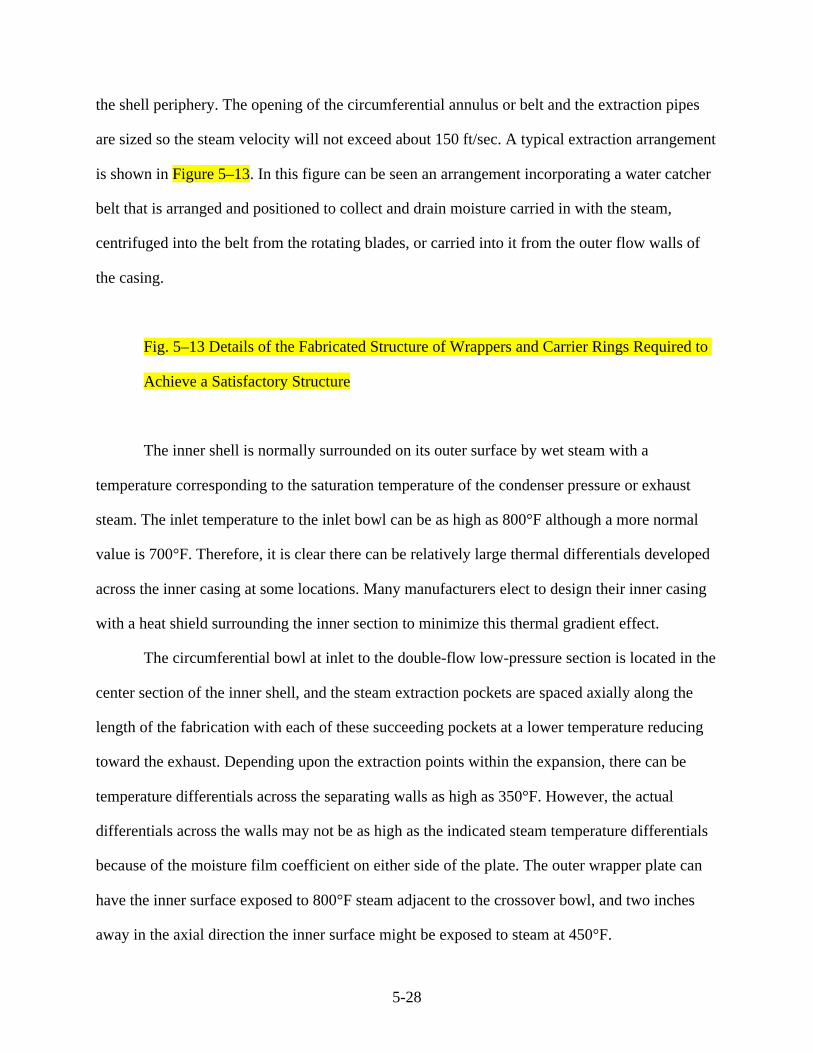
the shell periphery. The opening of the circumferential annulus or belt and the extraction pipes
are sized so the steam velocity will not exceed about 150 ft/sec. A typical extraction arrangement
is shown in Figure 5–13. In this figure can be seen an arrangement incorporating a water catcher
belt that is arranged and positioned to collect and drain moisture carried in with the steam,
centrifuged into the belt from the rotating blades, or carried into it from the outer flow walls of
the casing.
Fig. 5–13 Details of the Fabricated Structure of Wrappers and Carrier Rings Required to
Achieve a Satisfactory Structure
The inner shell is normally surrounded on its outer surface by wet steam with a
temperature corresponding to the saturation temperature of the condenser pressure or exhaust
steam. The inlet temperature to the inlet bowl can be as high as 800°F although a more normal
value is 700°F. Therefore, it is clear there can be relatively large thermal differentials developed
across the inner casing at some locations. Many manufacturers elect to design their inner casing
with a heat shield surrounding the inner section to minimize this thermal gradient effect.
The circumferential bowl at inlet to the double-flow low-pressure section is located in the
center section of the inner shell, and the steam extraction pockets are spaced axially along the
length of the fabrication with each of these succeeding pockets at a lower temperature reducing
toward the exhaust. Depending upon the extraction points within the expansion, there can be
temperature differentials across the separating walls as high as 350°F. However, the actual
differentials across the walls may not be as high as the indicated steam temperature differentials
because of the moisture film coefficient on either side of the plate. The outer wrapper plate can
have the inner surface exposed to 800°F steam adjacent to the crossover bowl, and two inches
away in the axial direction the inner surface might be exposed to steam at 450°F.

5-29
The outer surface at this same location is exposed to the wet, cool condensing steam if no
thermal barrier is used. These multi-directional thermal gradients can induce extremely high
stresses and possibly cause casing distortions. If the stresses induced by these thermal gradients
are in excess of the yield strength of the material, then the distortions of the inner casing could be
permanent. Such distortions of the inner casing could result in clearance rubs and possibly
broken welds on reinforcing ribs and struts and therefore leakage at the various steam tight joint
faces. Should these stresses induce ruptures in the joining welds within the casing these can be
extremely difficult to access for weld repair.
Cast Low-Pressure Sections
While the majority of low-pressure casings are produced as fabrications, there are a
number of manufacturers that find that casting is still suitable because it is economical, reliable,
and capable of producing an effective product. The material used can be either cast iron or steel.
The principal material is cast iron. There are two forms of iron in use—graphite iron and the
spheroid graphite type. Cast iron is a material that is very suitable for casting, and it produces a
good quality form. Unfortunately the simple graphite cast iron cannot be easily upgraded if
defects are found. However, the spheroid graphite is readily welded and is therefore a suitable
material. Cast steel can be easily upgraded. Many modern two-casing low-pressure designs will
employ fabrication for the outer casing and casting for the inner casings.
Shown as Figure 5–14 is a large casting for an inner casing being turned after completion
of machining. The outer section into which this casing would be mounted would be produced by
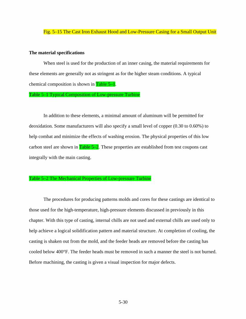
fabrication. Shown as Figure 5–15 is the cast outer portion of a smaller unit.
Fig. 5–14 A Cast Inner Low-Pressure Casing Being Moved After Machining
5-30
Fig. 5–15 The Cast Iron Exhaust Hood and Low-Pressure Casing for a Small Output Unit
The material specifications
When steel is used for the production of an inner casing, the material requirements for
these elements are generally not as stringent as for the higher steam conditions. A typical
chemical composition is shown in Table 5–1.
Table 5–1 Typical Composition of Low-pressure Turbine
In addition to these elements, a minimal amount of aluminum will be permitted for
deoxidation. Some manufacturers will also specify a small level of copper (0.30 to 0.60%) to
help combat and minimize the effects of washing erosion. The physical properties of this low
carbon steel are shown in Table 5–2. These properties are established from test coupons cast
integrally with the main casting.
Table 5–2 The Mechanical Properties of Low-pressure Turbine
The procedures for producing patterns molds and cores for these castings are identical to
those used for the high-temperature, high-pressure elements discussed in previously in this
chapter. With this type of casting, internal chills are not used and external chills are used only to
help achieve a logical solidification pattern and material structure. At completion of cooling, the
casting is shaken out from the mold, and the feeder heads are removed before the casting has
cooled below 400°F. The feeder heads must be removed in such a manner the steel is not burned.
Before machining, the casting is given a visual inspection for major defects.

5-31
After rough machining the casting is given a nondestructive examination by magnetic
particle methods in accessible areas and radiographic examination in any weld preparation
regions
Acceptance level of casting defects
It is necessary to have established acceptance standards available for any casting faults
that might be found. The following criteria are intended to provide guidance only. There may be
other standards established by individual manufacturers for their units based on their
requirements and experience.
Visual acceptance standards. Folds, cavities, and clustered porosity with a depth greater
than 5% of the wall thickness should be removed by grinding. If the depth of the resulting cavity
is less than 10% of the wall thickness and the locations of the cavity are not in a region subject to
high stress levels, then these can often be accepted. It is best if the cavity is acceptable to blend it
out at its edges. If the cavity is greater than 10% of the wall thickness, then it should be weld
rebuilt and the requirements of stress relief applied.
Magnetic particle acceptance standards. Acceptable linear indications for critical and
non-critical regions are shown in Table 5–3. Surface defects are not permitted at planned weld
positions or at defect excavations. Discontinuous linear indications are considered acceptable
where the separation between adjacent indications is at least four times the length of the larger of
the two indications.
Table 5–3 Acceptable Magnetic Particle Inspection

5-32
If as a consequence of this magnetic particle examination unacceptable defects are found,
then they should be excavated and weld repaired. After weld repair the casting should be
subjected to a stress relief cycle.
Defects in machined areas. The casting must be free from sub-surface defects which
would be exposed on machining. Defects classified as being greater than ASME schedule 1
found by radiography in scheduled weld regions are not acceptable. Any such defects in this area
should be repaired by welding.
Welding repairs. If it becomes necessary to weld repair defects in the cast shells, the
faults must first be excavated by some suitable means such as grinding and/or chipping,
machining, or arc-flame gouging. In some areas it is necessary to grind smooth the excavations
before the repairs proceed. The normal method of weld repair is manual metal arc. It is also
necessary to preheat the casting before repairs begin and to maintain the preheat temperature
throughout the repair procedure. Preheat temperature is from 150 to 300°F. Depending on the
material and whether localized preheat is used, this must extent for a least 10 in. in all directions
surrounding the repair. As the filler material is laid in, it must be continually inspected to ensure
no cavities remain in regions where they could lead to cracking as the unit ages.
Heat treatment. When the casting requires heat treatment, it should be loaded into the
oven and heated at a temperature ramp rate that should not exceed 200 to 225°F/hour (hr). For
annealing, the temperature should be raised to about 1700°F and for stress relieving to 1100°F.
These actual temperatures depend on the material. Once the treatment temperature has been
achieved evenly throughout the oven, these temperatures should be maintained for a period of
one hour for every inch of thickness of the thickest wall in the casing, but not less than a
minimum period of 12 hours.
Machining. The large physical size and weight of these castings, particularly for the half
speed (1500 and 1800 rpm) units, makes their handling and turning a complex operation because
5-33
they are normally much larger than the high and reheat section elements. The machining process
is essentially the same as for the high-pressure elements, and final machining requires the halves
be firmly bolted together and preferably supported in the manner as they are to be installed in the
field. If this is not done, these casings will tend to deflect when installed in the outer casing, and
the steam path grooving or support surfaces will no longer be concentric because the casing will
have a different sag form.
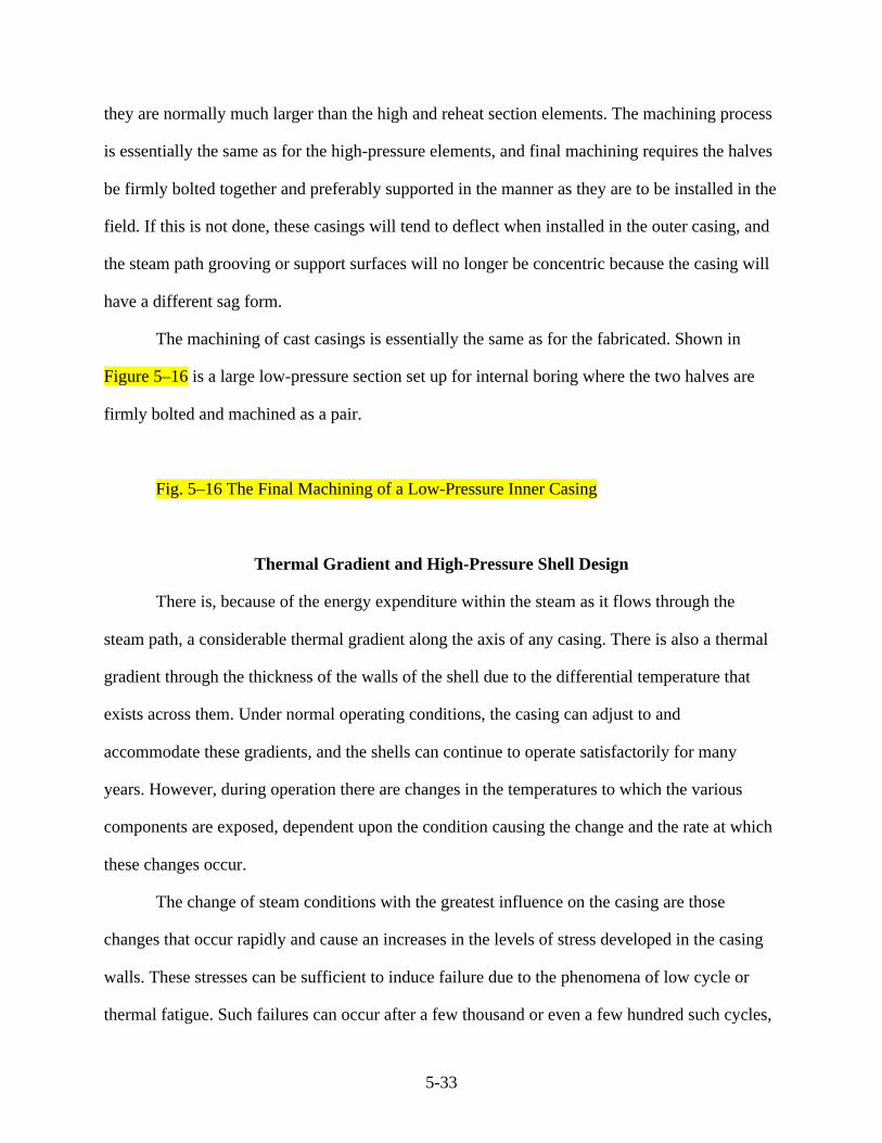
The machining of cast casings is essentially the same as for the fabricated. Shown in
Figure 5–16 is a large low-pressure section set up for internal boring where the two halves are
firmly bolted and machined as a pair.
Fig. 5–16 The Final Machining of a Low-Pressure Inner Casing
Thermal Gradient and High-Pressure Shell Design
There is, because of the energy expenditure within the steam as it flows through the
steam path, a considerable thermal gradient along the axis of any casing. There is also a thermal
gradient through the thickness of the walls of the shell due to the differential temperature that
exists across them. Under normal operating conditions, the casing can adjust to and
accommodate these gradients, and the shells can continue to operate satisfactorily for many
years. However, during operation there are changes in the temperatures to which the various
components are exposed, dependent upon the condition causing the change and the rate at which
these changes occur.
The change of steam conditions with the greatest influence on the casing are those
changes that occur rapidly and cause an increases in the levels of stress developed in the casing
walls. These stresses can be sufficient to induce failure due to the phenomena of low cycle or
thermal fatigue. Such failures can occur after a few thousand or even a few hundred such cycles,

5-34
dependent upon the severity of the temperature change and the stress levels and the normally
severe concentration of stress that exists at these points. Figure 5–17 shows typical cracks in a
high-pressure unit due to the phenomena of low cycle fatigue. (D.P. Timo 1970) This crack
initiates at a sharp female corner where stress concentration is high.
Fig. 5–17 Portion of a High-Pressure Shell Showing the Circumferential Cracks Formed
in the Filet Radii Positions as a Consequence of Thermal Cycling
It is of interest to consider the magnitude of stress occurring across any component due to
temperature mismatch between an inner hot surface and an outer cooler surface. Consider an
element of shell wall shown in Figure 5–18 where the temperature on the inner hot surface is
shown as T1 and on the outer cooler surface as T2. In this wall, the temperature gradient or
mismatch is _T. Consider the mean gradient or change of temperature in three cases.
Fig. 5–18 Temperature Profiles Through the Walls of a Casing Under Various Heating
Cycles
Linear temperature degradation. Figure 5–18a shows a casing under normal operating
conditions with a gradient that is practically linear from T1 to T2. In this case a compressive
stress will exist between the hotter wall and the neutral axis and a tensile stress from the neutral
axis to the colder surface. From the zero stress of the neutral axis to the maximum stress in the
outer fibers of the wall material, there will be a local temperature gradient _T equal to 1/2(T1-
T2), and the stress will have a maximum value of fs.
fs = ∆T . µ . E
1 - S (5.1)
5-35
where
fs = stress
_ = linear coefficient of thermal expansion
E = young modulus
S = poisson ratio
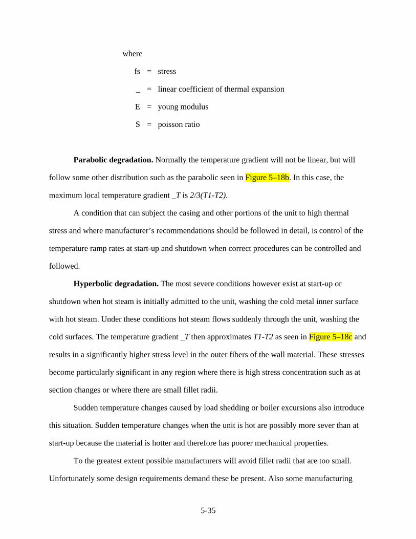
Parabolic degradation. Normally the temperature gradient will not be linear, but will
follow some other distribution such as the parabolic seen in Figure 5–18b. In this case, the
maximum local temperature gradient _T is 2/3(T1-T2).
A condition that can subject the casing and other portions of the unit to high thermal
stress and where manufacturer’s recommendations should be followed in detail, is control of the
temperature ramp rates at start-up and shutdown when correct procedures can be controlled and
followed.
Hyperbolic degradation. The most severe conditions however exist at start-up or
shutdown when hot steam is initially admitted to the unit, washing the cold metal inner surface
with hot steam. Under these conditions hot steam flows suddenly through the unit, washing the
cold surfaces. The temperature gradient _T then approximates T1-T2 as seen in Figure 5–18c and
results in a significantly higher stress level in the outer fibers of the wall material. These stresses
become particularly significant in any region where there is high stress concentration such as at
section changes or where there are small fillet radii.
Sudden temperature changes caused by load shedding or boiler excursions also introduce
this situation. Sudden temperature changes when the unit is hot are possibly more sever than at
start-up because the material is hotter and therefore has poorer mechanical properties.
To the greatest extent possible manufacturers will avoid fillet radii that are too small.
Unfortunately some design requirements demand these be present. Also some manufacturing

5-36
techniques require and produce such radii as a function of the technique itself. Cast surfaces,
particularly those internal to the steam inlet annulus that cannot be inspected visually and are
difficult to access, are prime candidates for producing regions where stress concentration can be
high.
The temperature gradient, and therefore the thermal stresses developed in portions of the
shell, can be limited by adjusting the rate at which the boiler conditions change or by adjusting
the turbine start-up rate. Unfortunately it is inevitable that during the life of the unit, there will be
some start-ups in which the thermal stress exceeds the yield strength of the material in some
portions of the shell. Similarly, there will be uncontrollable excursions where these stresses are
exceeded. Such situations are regrettable but can and must be accepted. The immediate and
cumulative effects of the excessive plastic strains induced must be understood and be readily
measurable.
In an effort to understand and limit this effect, many turbine builders have introduced
systems of measuring, recording, and aggregating the contribution of each start-up temperature
change or excursion, whether the induced thermal stress is of a high or low magnitude, toward
initiating a surface crack. The level of temperature mismatch between main steam and initial
metal temperature at start-up—temperature change—is converted to a low-cycle fatigue index
(LCFI). A typical curve of such an index is shown in Figure 5–19.
Fig. 5–19 LCFI as a Function of Temperature Changes
When the summation of all individual indices over the years of the unit’s operating life
reaches 100%, there is a possibility a surface crack will have initiated. This may not be harmful,
and it may require a further 100% aggregation for the crack to propagate to a significant depth
and even more operation before rupture would occur. If cracks are discovered early in their life,

5-37
then they can normally be removed by grinding. However, the removal of material will not solve
the problem created by temperature transients. If the crack is in a position where grinding can be
undertaken, then grinding can slow the rate at which the crack will propagate, but will not
prevent its reoccurrence.
High thermal stresses and the resulting accumulation of high individual indices can be
prevented by ensuring the temperature of the steam washing the inner surface is only slightly in
excess of the temperature of the core of the metal. If possible, the mismatch temperature should
be limited to values between -50 and +100°F, although acceptable outer limits are -175 and
+270°F. Here, a minus sign (-) indicates the main steam is cooler than the internal metal
temperature and a plus sign (+) indicates the main steam is hotter than the metal. The actual
values of acceptable temperature differentials for any unit will depend upon various factors
including the thickness of the metal section and the thermal conductivity of the shell material.
These recommended temperature differentials are normally the limiting factor to unit
start-ups, and the average thermal gradient during operation should not exceed the recommended
if an acceptable life is to be expected from the equipment. There may be some parts of the unit
where steady-state temperature differences larger than this will occur during normal operation. In
such cases, parts will have been designed to accommodate this and be of suitable materials and
form to provide the degree of flexibility required to prevent excessive stress.
Estimating Low-Cycle Fatigue Life
The model just discussed for considering the production of thermal stresses and their
effect on casing life together with the introduction of low cycle fatigue cracks, although very
simple, provides a relatively simple tool for estimating casing life consumption due to start-up,
shutdown, and during operation transients when large temperature changes occur.

5-38
The life expenditure that occurs during any unit transient is a function of three
factors—the magnitude of the thermal stress induced in the shell, the material properties of the
shell, and the environmental temperature at which the change has occurred.
Any component repeatedly subjected to stresses beyond the yield strain of the component
material at its operating temperature will develop cracks in a finite number of cycles. The
number of cycles required to initiate these cracks is a function of the stress level.
Turbine shells are a relatively complex form, and they contain regions where during
operation there is a considerable degree of stress concentration in the parts that are subject to
biaxial loading. Therefore, the calculation of actual stress levels by traditional methods is
difficult, although finite element methods have allowed a much better understanding of the loads
and stresses involved in casings. Because of these difficulties, designers find it is of considerable
advantage to calibrate experimental values of stress against calculated values, which are
normally determined by finite element methods.
Figure 5–20 shows a portion of an outer casing scale model equipped with strain gauges
used to predict actual values. These stresses are then compared with calculated values, which
permits experimental factors to be established which can be applied to other casings with similar
geometries to obtain an adequate degree of accuracy.
Fig. 5–20 Scale Model of an Outer Shell Instrumented With Strain Gauges to Help
Establish Stress Levels
In any repeated stress/strain situation in which the stresses developed within the
component are in excess of the yield stress in tension and compression, it is usual practice to plot
the total (elastic plus plastic) strain elastic plus static (EET) against cycles in determining the life
factor for the component. Two curves for a typical shell material are shown as Figure 5–21. The

5-39
materials selected for any component have a considerable effect on the low-cycle fatigue. In
Figure 5–21curve A being a low strength relatively ductile alloy and curve B a stronger, less
ductile one.
Fig 5–21 Elastic + Plastic Strain as a Function of Stress Cycles for Two Different Shell
Materials
It has been shown that at room temperature, low-cycle fatigue life may be predicted by
the following expression. (Tavernelli and Coffin 1961)
∆εp = 0.5 Ln [100/(100 - %Ra)]
N (5.2)
where
__p = plastic strain range
%Ra = percent reduction in area measured in a tensile test specimen
N = the number of cycles to cracking
This expression is valid in the high strain range where the ratio of plastic to elastic strain
is high. In any casing form, it is normal for the designer to determine the number of cycles N to
initiate a crack. This number is factored into the total design considerations including the
selection of the material to be used.
Thermal Gradient in the Low-Pressure Inner Casing
In many low-pressure sections, problems are encountered due to thermal gradients
causing permanent distortion of the inner casing. It is normal for these gradients to occur in both
the axial and radial direction. Therefore, the distortion which results can occur in a complex form
5-40
in the casing structure causing permanent set in both directions. In addition to the predictable
temperature differentials from the expansion and extraction of steam, it is known that the skin
surface temperature of the outer surface of the inner casing varies in an unpredictable manner
and is influenced by changes in load and varies from the upper to the lower halves at any
transverse section.
At exhaust from the last stage blade annulus, the steam is deflected to flow into the
condenser. However, there are spaces between the inner casing outer surface and the inner
surface of the top half outer casing. These spaces fill with flowing steam, which passes through
them to the condenser and the surfaces therefore attain steam temperature. This represents a
thermal gradient on the inner casing walls. However, many designs of inner casings are arranged
to include a thermal barrier attached to the outer surface of the inner casing. This barrier helps
ensure the temperature gradient across the wall is not as severe as that caused by the outer
surface of the inner casing attaining steam temperature.
There are within the exhaust hood factors that cause temperature variation and non-
symmetric flow. These include:
• unit load. As the unit load varies, so will the quantity of steam flowing through the
steam path, which will in turn modify the flow velocities and patterns through the
spaces between the hoods.
• exhaust pressure. As the exhaust pressure produced by the condenser changes, there
will be a change in the steam specific volume and the volumetric flow will change.
Also, as the condenser pressure changes so will the saturation temperature of the
steam that covers the metal surfaces. There will be changes in steam velocity and
temperature associated with condenser pressure changes.
• Rotational effect. While the flow pattern of the steam at exhaust from the last stage
blade annulus will be substantially axial, it will possibly have some tangential and
5-41
radial component to its flow. These effects will produce a total flow distribution that
is different from side to side within the casing. This side-to-side flow difference will
influence the total flow patterns within the hood, which will be sensitive to any small
change in either steam pressure or quantity.
In designing a low-pressure section, sufficient flow area must be made available to the
exhausting steam to minimize the pressure drop from the blade annulus to the condenser. There
are two important considerations to this requirement.
1. The exhaust blades will discharge their flowing steam into a diffuser that is produced
as part of the low-pressure section fabrication. The diffuser form is selected to
minimize losses associated with removing the steam away from the exhaust plane and
not impede further flow from the blades.
The diffuser is normally constructed from rolled plate that is either welded or bolted
to the inner casing. The axial distance from the exhaust blade annulus to the casing
end wall is limited, and it is difficult to achieve a perfect arrangement within the axial
length available. However, designs can be provided that allow a diffuser section to be
used and can be accommodated within the available axial space to help minimize the
losses which occur.
2. The hood structure must turn and divert the steam, normally downward, to the
condenser, causing a minimal frictional loss within the hood. Hoods are designed so
strategically placed diverter plates can turn the steam in an effort to keep the flow
density at any point relatively constant, avoiding excessive velocities and minimizing
frictional losses.

5-42
During operation, the inner casing must remain sufficiently rigid it is able to maintain
concentricity in the radial direction and retain axial alignment. It must do this and yet remain
sufficiently flexible it is able to respond to large temperature swings that occur within short
periods of time. These requirements of flexibility and rigidity are obviously contradictory.
However, it is important that alignment and rigidity requirements are addressed in the design
phase. If any forced compromise is required by one requirement, then it must be recognized by
and accounted for in defining the requirements of the other. These requirements can be
aggravated by any large temperature gradients, and the designer must anticipate the most severe
condition when defining the low-pressure sections.
There are various approaches that have been considered to solving the thermal gradient
problems encountered in designing and manufacturing the low-pressure casings. An attempt
could be made to reduce or eliminate the radial and axial gradients by insulating the various
members of the fabrication. Also, the radial gradient could be reduced by insulating the inner
surface of the wrapper plate. However, any insulation used would be exposed to wet steam, and
unless this insulation was impervious to water soak, it would immediately loose its insulation
properties on becoming wet. A ceramic insulation would overcome water soak problems but
would be unable to expand and contract adequately to accommodate casing movement.
To reduce or eliminate axial temperature gradients, the shell would have to be made of
several cylindrical sections to minimize conductive heat transfer. This would require making the
inlet bowl and each extraction belt a separate fabrication. This is obviously an expensive solution
since it would require a multiplicity of transverse flange faces and could present considerable
alignment problems. In addition, thermal cycling of the casing affects the bolting on flange faces,
and each separate fabrication would need to be supported individually from the lower half outer
casing.

5-43
Since there is considerable difficulty in reducing or eliminating gradients, the normal
engineering approach has been to design the structures so they are able to accept the anticipated
gradients and not have stresses induced in them which exceed the yield strength of the material.
This is the design approach currently pursued by manufacturers. It has so far proven to be an
acceptable solution, but the costs of producing the casings are increased by the use of more
expensive material and thicker sections in some locations than are required from the simple
consideration of normal (non transient) gradients.
The schematic of an inner shell, shown as Figure 5–22, indicates the predicted steam
temperatures and pressures at various locations within an inner shell arranged for steam
extraction pockets. These conditions are consistent with normal operation and will change during
transient operation. In this type of design, the only connections from the inner support sections to
the cooler wrapper plate are relatively thin supporting ribs. These ribs are free to deflect and
move axially under the influence of both thermal growth and diaphragm thrust. This type of
design eliminates the compressive stresses that would be present in the ribs if these had been
massive structures and the extraction pockets or belts had not been circumferential, thus
permitting limited axial movement.
Fig. 5–22 Temperatures at Various Locations in a Fabricated Low-Pressure Casing
High-Pressure Turbine Shell Materials
Advancing steam conditions and increases in diameter, particularly for half-speed
machines, have required a continual improvement in both the composition and mechanical
properties of the material and the manufacturing techniques used to produce steam turbine casing
shells. This is particularly important when applied to high-temperature, high-pressure units.
Casings are produced from alloy steels, and the castings are carefully controlled both to ensure

5-44
mechanical strength and freedom from casting defects which have the capability to compromise
the integrity of the shell.
For temperatures up to about 750°F, a material that is produced to American Society for
Testing and Materials (ASTM) A27 Grade 65-35 will normally be acceptable. The mechanical
and chemical specifications for this material may be modified by closer control of the chemical
constituents and the heat treatment undertaken. However, the material will generally meet the
overall requirements of this specification. For increased temperatures a more suitable
specification is one that accords closely with the requirements of ASTM A356 Group 8, and for
the highest steam temperatures up to about 1100°F the ASTM A356 Group 9 specification is
most suitable.
Typical chemical constituents of these materials are shown in Table 5–4 and the
minimum acceptable mechanical properties in Table 5–5. Turbine builders will modify these
basic requirements to suit their particular philosophies, applications, and design requirements.
This is acceptable and reflects the experience from many years of operation.
Table 5–4 Turbine Shell Castings Nominal Chemical Composition
Table 5–5 Turbine Shell Castings Minimum Mechanical Properties
In addition to sulfur and phosphorus, there are normally other trace elements such as
antimony, arsenic, and tin, present in the material. However, these amounts should be kept to a
minimum. Aluminum is generally not tolerated and there are two basic reasons for this. First,
aluminum has a greater affinity for the elements with which vanadium should form a compound
to increase the strength of the material. Therefore, if aluminum is present it will effectively
5-45
reduce the mechanical strength of the casting. Second, aluminum present in a casting operating at
high-temperatures weakens the component’s resistance to creep stress.
Therefore, freedom from aluminum and general purity is essential because these castings
will need to be weld repaired and upgraded after casting and before final machining is
completed. Therefore, high levels of impurities will compromise the strength and integrity of the
shells. Because of the heat fusion processes and then the stresses that will develop in the shells,
the control of the chemical constituents is critical.
The addition of a small quantity of copper acts to reduce the incidence of washing and
wire drawing erosion that can affect a casing. Therefore, for nuclear applications a small amount
of copper is often specified.
The service to which casings are put requires close control of their chemical constituents,
to help ensure their long-term service will be at an acceptable level. This will particularly require
the specified chemical content plus any nickel and aluminum be controlled so as not to exceed a
specified carbon equivalent. For the lower temperature material, ASTM A27 is the controlling
formula:
C + 0.333 [Mn + Cr ] + 0.167 [ Si + Ni ] + 0.500 Mo = 0.750 (5.3)
For decreases of carbon content below the maximum specified, down to a specified
minimum, the manganese content may increase, although a maximum level is placed on this.
Again the turbine designer may require slightly different mechanical properties than
those contained in Table 5–5. These requirements will be detailed in the material specification.
On the basis of present operating experience, it is considered the mechanical properties
for high-pressure/high-temperature shells operating below the creep range are adequate if the
materials exhibit a low Charpy impact transition temperature. (Rogers and Brewer 1964–65)

5-46
The complex forms required for shells, coupled with high initial steam conditions, make
castings the obvious manufacturing process for producing these components. Many of the highly
stressed regions in the casing are required to be thick and these occur in regions subject to rapid
temperature changes. The hardenability of the alloy used to produce these shells should be
adequate to obtain the correct properties throughout the section. Since both inlet and outlet
connections must be made to the casings, the materials must be weldable.
Faults are a common factor of casting and repairs must be made by the deposition of weld
material. To permit adequate wall thickness and the inevitable stress concentrations, high rupture
strength and rupture ductility are necessary. (Curran and Timo 1964)
Steel Plate for Low-Pressure Casings
The low-pressure outer hood and inner casings are normally produced by weldments or
steel fabrications. These parts are large and subject to considerable loading due to both the
dynamics of the unit and the downward pull of the condenser. The low-pressure casings must be
free to move when subject to axial thrusts and yet maintain alignment. For these reasons, the
materials from which the fabrications are produced must be stable, able to be welded, and
maintain their long life integrity.
The steel used for these hood fabrications is a low or intermediate strength carbon-silicon
type. This plate is normally manufactured by the open hearth, basic-oxygen, or electric furnace
process. Because of the large amounts of free water that can be present in the low-pressure
section of modern units, it is often necessary to use stainless steel inserts at certain locations
because of the tendency of the carbon steel of the casings to loose material to both moisture
impact and washing erosion.
The plate specifications

5-47
The chemical composition of the carbon steel plate used to manufacture both outer and
inner casings is relatively simple, the constituents being dependent upon the loads the
components will carry and the plate thickness. The steel contains silicon generally in the range
0.15 to 0.30 percent, the exact content being consistent with obtaining the required mechanical
properties and limiting the carbon content to the lowest practical level. (ASME Specification
A284-70a)
Despite this specified composition, there is normally some variation of composition
throughout the thickness of the plate.(Rollason 1956) This variation occurs as a consequence of
the rolled in inclusion from the initial ingot. There are also some impurities that segregate and
concentrate at other locations and are given a linear location during the rolling process. These
cannot be avoided but can be allowed for in the design of the component. Normal chemical
composition and mechanical properties are shown in Tables 5–6 and 5–7.
Table 5–6 Chemical Composition of Weldable Quality Steel Plate for Low-Pressure
Fabrications
Table 5–7 Mechanical Properties of Weldable Quality Steel Plate for Low-Pressure
Fabrications
In addition to the mechanical properties listed in Table 5–7, another important ductility
characteristic of this material is the bend test. It is normal for samples of this material to be bent
through 180 degrees without producing evidence of any surface cracking. The bend radius is
established as a function of the plate thickness.
Plate faults

5-48
Plates less than about four inches in thickness are normally delivered to the turbine
manufacturer in the as-rolled condition. Therefore, before being used in any fabrication, these
plates must be descaled by shot blasting or some similar method. After this descaling process
surface faults are occasionally visible.
Molten steel contains soluble and insoluble gases and metallic and non-metallic
inclusions. When molten steel is poured into an ingot mold and cools, solidification starts at the
mold/steel interface and continues towards the center of the ingot. Segregation of the impurities
that normally have a lower melting point and the entrapment of gasses tend to take place at the
center of the ingot. The manufacturer can produce a rimmed steel, a capped steel, a semi-killed
steel, a killed steel, or a vacuum deoxidized steel. The degree of segregation progresses from
pronounced in a rimmed steel to virtually none in a vacuum degassed steel.
Therefore, the production process has a considerable effect on the quality of the steel.
Porosity in the ingot also follows the same gradation, going from considerable in the rimmed
steel to none in the vacuum degassed product. However there is a cost premium associated with
each of these processes, with cost increasing with the steps taken to limit the quantity and form
of the impurities present in the final plate.
When the ingot has been poured, the plate is rolled and any inclusions are flattened and
spread out. Dispersion takes place, and depending upon the degree of rolling, the resulting
platelets or inclusions may or may not be significant. Gases leave voids in the ingot, and with
sufficient hot rolling, even deep-seated blow holes will weld up and disappear. If not, the plates
will exhibit some level of lamination.
The manufacturing processes, including the accompanying segregation during cooling,
gives rise to certain types of faults in the plates.
The major internal defects
5-49
Laminations. These are continuous faults that normally occur at or near the center
thickness of the plate. These faults are due principally to gasses or pipe that will concentrate at
the upper axial center of the ingot and become rolled into the plate. Figure 5–23 shows a cross
section of a typical lamination in a plate. Laminations can also be caused by rollover during the
rolling process. This rollover occurs when there is a doubling of the section during rolling. This
results in multiple layers or a pinching of excess material that is squeezed over the section
entering the rolls. These multiple layers form of lamination may occur at any thickness position
of the plate.
Fig. 5–23 Laminations and Lamellar Tearing in a Plate Adjacent to a Weld
Rolled out inclusions. During the cooling process, the dispersed non-metallic inclusions
can become trapped in the ingot in isolation from other impurities or defects and these are
surrounded by the steel. Being non-metallic, these inclusions form a non-continuous area in the
form of planes of incomplete fusion in the plate as shown diagrammatically in Figure 5–24a.
Fig. 5–24 Rolled Out Inclusions Near the Center Section of a Plate a, and the Lamellar
Tearing Under the Action of a Force P
In isolation, or in small groups, these small laminar type inclusions are not necessarily
detrimental to the strength of the plates. However, if they occur in the vicinity of a weld, their
effect can become significant. Under the influence of a weld and the internal stresses this metal
fusion introduces, decohesion of laminar-type inclusions will take place when the plates are
stressed in a direction transverse to the plane of the inclusions. When such decohesions occur in
the platelets that are close together, the resulting phenomena is known as lamellar tearing. This

5-50
tearing has a characteristic morphology being step-like in appearance but tending to follow
planes parallel to the rolled surface of the plates.
The planar areas of decohesion are interconnected by near vertical shear faces normal to
the plate surface as seen in Figure 5–24b. For lamellar tearing to occur, two conditions must exist
in the plate or welded joint. There must be sufficient through-thickness stresses and strains on the
joint, and there must be low through thickness ductility.
The through thickness stresses and strains in a low-pressure shell can result from thermal
distortion during welding and later in service due to thermal loading particularly during transient
operation when there is heating and quenching of the shells.
When lamellar tearing occurs, the initial fracture is usually at a large inclusion to metal
interface. Regions of decohesion then link with other regions by shear fracture until
progressively the final linking of the larger areas results in gross cracking.
Lamellar tearing can be detected by nondestructive examination (NDE) methods.
Radiography is difficult to apply due to unknown crack orientation and accessibility. However,
for sub-surface cracks they are detectable by straight beam or angle beam ultrasonics. Figure
5–25 shows diagrammatically three typical lamellar cracking profiles that can be present in the
region of a weld.
Fig. 5–25 Various Tear Patterns Adjacent to Weld Joints
The major surface defects
Surface flaws. If a surface flaw or defect does not decrease the net cross sectional area of
the plate or result in potential stress raising effects, it can be ignored. Surface defects are in
general the result of faults and irregularities introduced during the steel pouring and rolling
process. Although surface defects are generally not detrimental to the performance and

5-51
mechanical strength of the plate, care must be exercised when forming or bending to ensure they
are not present in regions where they will contribute to any stress raising situations.
Ingot cracks. These cracks are the result chiefly of high pouring temperatures (values
considerably in excess of the solidification temperature). This high-temperature pouring results
in an inhomogeneous crystalline structure on cooling which has zones of weakness extending
from the edge of the ingot in towards the center. On rolling, these planes of weakness are sheared
and are present in the final plate.
Scabs. Scabs are caused by metal splash against the mold during the pouring process.
These splashes onto the side of the mold cool rapidly and oxidize. When the ingot is rolled, these
surface inclusions appear as surface scabs. This defect can be minimized by bottom pouring,
mold coating, and by close adherence to pouring rates and procedures.
Seams. These are the longitudinal cracks or openings that appear on the surface of semi-
killed steel. These are the result of longitudinal or transverse cracks in the ingot that are
elongated during the rolling process.
Burned steel. This form of damage is the result of flame impingement on the surface of
the ingot, usually at the corners. This intense heating causes oxidation at the grain boundaries
and results in a rupturing or tearing during rolling.
Cinder patches. These patches are usually caused by non-metallic pickup from the
soaking pits.
Laps. These are the result of overfilling of the mold, which in turn causes fins or
projections that are turned down in subsequent rolls. Laps are often deep and the plate cannot be
salvaged.
Casing Weldment Considerations

5-52
Fabrication from plate is the principal method for producing low-pressure casing
components. The duty and stresses to which these components are subjected demands attention
be paid to the detail of the welds, which are required to ensure a high degree of mechanical
integrity. In designing a fabricated casing, there are certain details of the structure that must be
considered that are fundamental to its strength and therefore acceptance. In general, to achieve
mechanical strength, the welds required to produce a suitable shell require full penetration. This
means that access to both sides of many structural plates must be available and there must be
sufficient space to permit internal welding of the structure.
During the life of the unit there will be many occasions, including the manufacturing
phase and during maintenance outages, when the casing upper halves particularly will require
lifting. To facilitate this lifting, the casing must be fitted with lifting lugs to allow the component
to be raised and moved without causing any form of twisting or significant distortion that could
in any way be permanent or affect its ability to be reassembled and maintain alignment and
running clearances. These lifts must be so designed that they will not overload individual
structural welds to the extent there is a rupture in any joint. Many upper half low-pressure
sections carry the diaphragms assembled into them. Therefore, when this upper half is raised the
diaphragms will lift with the casing, the casing must therefore be of sufficient strength it is able
to carry and support these diaphragm halves.
It is in the interest of the designer to select weld configurations that minimize overhead
and vertical welding to the greatest extent possible. While these forms of construction cannot be
eliminated entirely the individual pieces of the fabrication should be designed to permit as much
downhand welding as possible. Such considerations are of particular importance for site work,
which must be accomplished as quickly as possible and then be available for evaluation by non-
destructive means.

5-53
The steels used for the fabrication of low-pressure casings do not require a preheat prior
to welding. However, at completion of the total fabrication and before machining, it is a good
and recommended practice to place the entire structure in a furnace for stress relief. Typically a
large fabricated structure should have a maximum heating rate of about 150°F/hr and be heated
to a stress relief temperature of 1100 to 1200°F for a minimum period of six hours. At
completion of this stress relief cycle, the structure should be cooled at a rate of 500 to
600°F/hour. The fabrication should not be air quenched.
In supporting the structure in the furnace, care should be taken to ensure all parts reach
furnace temperature. Sufficient thermocouples must be placed on the fabrication at strategic
locations to ensure a uniformity of temperature is maintained. The stress relief period should
begin when the specified temperature has been reached by all parts of the structure. In the
furnace, the casing should be supported so there is no sagging due to its own weight, otherwise
permanent distortion can result.
To provide a permanent record of the stress relief process, the following documentation
should be prepared and made available, as requested, to the purchaser.
• A photograph of the furnace load identified by serial number, material specification,
or other information allowing immediate and unchallengeable identification.
• A thermocouple chart showing individual location and thermal history of the heat-
treating process.
Should any repair welding be necessary after stress relief and inspection, it is necessary
to consider repeating the stress relief process. This will require evaluation and will be dependent
upon the amount of repair required and its location. The need for this should be determined from
an evaluation and the perceived need in relation to the stress and duty of the repaired area.

5-54
At completion of the fabrication process, and sometimes during the manufacturing phase, NDE
of the weld joints should be undertaken to ensure the joints meet the engineering definition and
has therefore the greatest probability of achieving a suitable level of mechanical strength.
The quality of the welds is in general established from both visual examination and crack
detection techniques. Structural welds must be completed by qualified welders and the work
completed in the correct sequence to approved procedures.
The most suitable method for examining structural welds for integrity is by ultrasonic
examination, although it is possible in some locations to use magnetic particle inspection (MPI).
These examinations should be made after stress relief, and if considered necessary, before heat
treatment. The purpose of this evaluation is to ensure further upgrading and repair will not be
required after the stress relief. Hydrostatic testing is often used with large fabrications and has
generally been found to be satisfactory in proving the design strength and structural integrity.
This test provides a means of checking for leaks.
Smaller fabrications use oil as the filling fluid and larger fabrications use water,
sometimes with dye or dioxide in solution. The test pressures are usually specified in the range
of 1.5 times the maximum pressure the casing will experience. Some manufacturers have used
low-pressure neon gas for this test.
If a fluid is to be used to conduct the hydrostatic test, it is important that the casing be
filled with the test fluid and then left for a sufficient period so the fluid can reach a temperature
close to the ambient condition. A satisfactory test cannot be conducted when the casing is full of
cold fluid. Under these circumstances there is a tendency for condensation to form on the casing
surface, and it is not possible to differentiate between leakage and condensation.
Casing Weldment Details
5-55
There are many factors involved in the selection of the geometry for any particular joint,
and it is impractical to make specific recommendations in a general discussion. The selection of
geometry and certain other factors are dependent upon an evaluation of the position, loading, and
accessibility of the joint to be made. The unit designer is not normally in a position to specify
one particular weld without reference to the manufacturing function of a supplier. This is
because weld geometry is a function of the welding process to be used, and there could be
several suited to any particular location within the total fabrication. It is normal for the welding
procedure to specify applicable welding codes, and those requirements must be satisfied. The
manufacturing engineer is primarily responsible for meeting code requirements.
The stresses developed in a turbine hood or casing structure are difficult to determine
with any degree of accuracy, and model testing is the most appropriate method available,
although this is being supplemented and perhaps to a degree superseded by finite element
analysis as experience accumulates. However, low-pressure sections are normally a standard
design and it is only necessary to establish stress patterns and magnitudes once for each design
for the most severe operating conditions. When this has been established, future units are built in
such a manner these maximum stresses can be tolerated and the unit continues to operate in a
satisfactory manner.
In defining weld requirements it must be recognized that over-welding can be as serious a
fault as under-welding, because over-welding can induce residual stress capable of causing
casing distortion. This can be difficult to correct. In selecting the weld for any location within the
unit, the following three considerations need to be addressed.
1. If the weld is to provide a path for the transfer of forces, a welded design is justified,
and the calculations necessary to determine stress levels and suitable weld sizes and
geometries are mandatory.

5-56
2. If the weld is simply to locate or hold parts together, full-length welds are invariably
wasteful and a few intermittent connecting welds will prove both more efficient and
economical.
3. If the plates being joined are to provide a pressure barrier—the steam pressure on the
two sides are different—then the welds must be constructed to produce isolation from
side to side.
In selecting the weld, it is necessary for the designer to address certain considerations
concerning the most appropriate form as follows.
• Are fillet welds acceptable and what size fillet is required? Will a single fillet be
sufficient, and is there access for a double fillet? If not, will a partial or intermittent
weld on one side be sufficient and acceptable?
• Are the stresses that will be developed at the weld shear, tensile, or compressive? The
stresses will dictate the type of weld and to some extent the sequence of welding.
• Are the stresses cyclic and is their magnitude sufficient to make fatigue a
consideration at the local operating temperatures? Is there a possibility of inducing
low-cycle fatigue into any of the joints?
• If the joint falls into the category of being subjected to a cyclic loading, which could
induce high stress values, what contour weld is required, and what surface finish must
be obtained on the welded surface and transition regions?
• Are fully penetrated welds required?
• Will partial penetration groove welds or fillet welds suffice as long as the full strength
of the plate is developed in shear or tension?

5-57
The specification prepared by the design engineer for any fabrication will define the
applicable welding codes, their requirements, and how they will be met. The actual fabricator, or
manufacturing engineer, is primarily concerned with and is responsible for meeting these various
requirements of the designer.
The selection of joint geometry is the responsibility of the designer, who will select the
joint form, plate thickness, and the welding techniques and materials to be used. The designer
will evaluate and should be aware of the loads to which the fabrication will be subjected, and
also if these loads are direct or cyclic. Therefore, the fabrication specification will typically
include the following information.
• Any code requirements to be met. This will identify both the code and any special
inspection requirements by regulatory bodies.
• The joint geometry. The five basic joint geometries are shown in Figure 5–26.
(Blodgett 1956)(AWS Standard Welding Symbols) The engineer will normally define
the joint requirements and any weld preparation required. The designer must
determine if a fully penetrated weld is required, if a butt weld will be sufficient, and
whether the welds should be continuous or intermittent.
Fig 5–26 The Five Basic Weld Joints
• The filler material and weld processes to be used. This could include stick size and
the sequence of laying in the material.
• The fabrication sequence. The sequence is established normally after detailed
discussion with the manufacturing or production department. This is necessary to
ensure access and to ensure those welds requiring additional strength can be prepared
for complete penetration and if necessary can be back gouged for greater integrity.

5-58
• Any requirement for preheat. Preheat which is not normally required in the
material used for turbine hood structures.
• Any stress relief requirements.
There are three types of weld—the fillet, the groove, and the plug weld. For turbine hood
fabrication only the first two need be considered. Typical joint configurations are shown
schematically in Figure 5–27.
Fig. 5–27 The Cross Section of Basic Weld Joints Used in the Fabrication of a Low-
Pressure Hood
Structural welding faults
In all structural welding, the opportunity exists for various forms of defect or fault to
occur. This is discussed further in “Whats Ailing That Weld?” in the Welding Journal, August
1997.
The result of these faults can be insignificant but can also be a source of mechanical
weakness causing weld distortion or high stress concentration in the various portions of the
structure involved. The most common faults are various forms of inclusion, cracks in the weld,
and undercutting:
Slag inclusions. Slag can be deposited within the weld as shown in Figure 5–28. These
inclusions can act as stress concentration centers. Such inclusions are captured in the base weld
deposit material during the deposition process. This is particularly common if the layers of weld
are deposited and the slag from one pass is not removed adequately before the next pass is
deposited.

5-59
Fig 5–28 Slag Inclusion Both Single and Cluster
Oxide inclusions. Oxide inclusions occur when the surfaces to be joined are not cleaned
of oxide before the welding process begins. The oxide scale from metallic surfaces will, if they
have a sufficiently high melting temperatures, drop into the weld pool and become trapped.
These inclusions like those caused by slag can introduce high stress concentration.
Porosity. Porosity is the result of gas pockets becoming trapped in the weld bead. These
beads can exist as small single voids or in clusters. In either case, these voids represent
discontinuities that can introduce high stress concentration and have the capability to generate
cracks. The forms of these inclusions are shown as Figure 5–29.
Fig. 5–29 Porosity Single and Cluster
GTAW-tungsten inclusions. The use of gas tungsten arc welding can, if procedures are
not followed in detail, result in tungsten particles from the electrode being trapped in the weld.
Crater cracking. These are cracks that occur in the heat-affected zone (HAZ) and are
normally a consequence of not breaking the arc correctly. A method of preventing or minimizing
their occurrence is to reverse the arc back into weld bead while reducing the welding current. A
schematic of such a crack is shown in Figure 5–30.
Fig. 5–30 Crater Cracking
Hot and cold cracking. Hot cracking is normally caused by the inclusion of excess
amounts of sulfur or phosphorus in the steel or incorrect methods of breaking the arc. This is a
form of crack that occurs while the components being joined are at high-temperature caused by

5-60
the welding process. These cracks tend to be transverse to the weld and are the result of excess
local shrinkage or excessive cooling rates at completion of the weld.
Cold cracking occurs after solidification of the weld material is complete and can initiate
days after the weld is complete. This is normally a result of hydrogen embrittlement. Cleaning of
the joint to remove moisture or any other liquid deposit before welding can help minimize the
occurrence of this condition.
Centerline cracking. A centerline crack is shown in Figure 5–31. This is a cold crack
that runs down the center of a single concave weld. This type of crack can initiate because the
weld bead is too small for the thickness of the plate, high joint restraint, the extension of a crater
crack, or poor fit up of the joint before welding proceeds.
Fig. 5–31 Centerline Cracking
Undercutting. Undercutting is shown in Figure 5–32. This occurs when the base metal
adjacent to the weld bead is cut or weakened at the intersection of the bead and base metal. The
result of this material removal is to reduce the load carrying capacity of the base metal and/or
increase stress concentration in that region.
Fig. 5–32 Undercutting
Incomplete fusion. This is a condition that occurs when the weld bead does not make
complete fusion to the base metal or even between passes. This is shown in Figure 5–33. The
principle causes for this condition are excessive travel speed, insufficient welding current, or
using too large an electrode. This condition is a natural location for high stress concentration to
occur and initiate major cracking.

5-61
Fig. 5–33 Incomplete Fusion
Welding Consumables
As important as the selection and preparation of the weld geometry are the consumables
that will be used in the fusion process. They have a major impact on the integrity of the weld.
These consumables include the electrodes or filler materials, the fluxes and gasses and even the
rate and sequence in which these elements are applied. In the manufacture of the electrodes, their
diameter and chemical composition must be controlled within close tolerances to ensure they
meet with the requirements set by their own engineering.
The storage and treatment of the consumables is important as some consumables will
deteriorate if not maintained in a suitable condition. For semi-automatic and automatic welding,
the filler wires and fluxes must be controlled and stored with exactly the same level of care.
High-Pressure Shell Manufacture
The majority of steam turbine high- and intermediate-pressure shells are produced by
casting. The majority of these are from a high-quality alloy steel. The casting process is complex,
and because of the elaborate form of the casting, and the duty to which it will be exposed, there
is a need to minimize casting faults which can occur if proven procedures are not followed in
detail. The majority of the faults that occur must be identified in terms of size and location, and
must then normally be excavated and upgraded. Such upgrading is an expensive process and can
add considerably to the cost of producing a quality casting. However, this is an essential step to
providing a safe and reliable shell.
The initial step in casting manufacture of a high-pressure turbine shell is the production
of a suitable pattern from which the shells can be cast. Since the form of the final shells can be
5-62
no better than the pattern from which they are produced, any effort and thought expended in the
production of the pattern, its design and manufacture can be easily justified. (Clymer 1968)
Patterns for large castings are often split vertically along their axial length to facilitate both their
manufacture and handling.
Some manufacturers produce a number of component pattern parts, from which a variety
of casting forms can be constructed for a variety of section and cycle arrangements. Also these
casings can, when necessary, provide any required internal configuration of the steam path. The
pattern must be made to help ensure the castability of the shell. This means arranging for steady
tapers in vertical walls, ensuring to the greatest extent possible a progressive solidification,
avoiding abrupt changes of section when this can be achieved, avoiding regions where stress
concentrations will occur, and using fluid form shapes rather than cubic.
Obviously, to achieve these requirements, a certain degree of compromise may be
necessary between those of the founder and those of the design engineer. Over the years of
experience gained in the production of such castings, a general agreement and knowledge of the
requirements of both parties has evolved, and an acceptable product can now be specified and
produced. It is usually possible to achieve a suitable balance and minimize potential fault
regions. Figure 5–34 shows the building of a turbine-casing pattern.
Fig. 5–34 Building the Pattern for a Casting of a High-Pressure Casing
The casting melt is prepared to the chemical specification of the designer, and the metal
is prepared by either the induction or electric furnace processes. When the melt is complete and
pouring begins, an analysis of composition is checked by making a ladle analysis from the initial
pour. It is also possible that by forced cooling an analysis of the ladle sample will be taken from
the furnace and completed before the pour begins to ensure the chemical composition is correct.
5-63
The chemical composition must comply with the engineering specification within close
tolerances. This composition must be checked, approved, and recorded. A moderate variation of
carbon content beyond the engineering specified upper limit is considered acceptable by some
manufacturers, particularly when thicker sections are involved. Such excess carbon can help to
prevent carbon segregation in the casting and also help ensure a more homogeneous section and
achieve the specified mechanical properties throughout its thickness. However, such a decision
and the potential consequences of excess carbon must be carefully considered before acceptance.
If internal chills are used, their number, type, composition, and location in the casting
must be selected to ensure the required solidification characteristics are achieved.
When the casting has been poured, solidified, and cooled to about 750°F, it is shaken out
of the mold. At this point, it is normal to blast clean and anneal. The annealing temperature is
dependent upon the chemical composition of the casting. Annealing temperatures range in
specifications from about 1250 to 1750°F. The heat soak period usually depends upon the casting
thickness, but is very rarely less than 10 hours. During this annealing period, a deviation of
furnace temperature of more than about 75°F is unacceptable. At completion of the heat soak, it
is normal to let the casting cool in the furnace to a temperature in the range 400 to 575°F.
At this point the casting can be removed from the furnace and the heads burnt off. Care is
taken to maintain the casting temperature. In burning off the heads, the casting main body is not
burnt. Remaining portions of the heads are removed by grinding and chipping.
If the casting is to be subjected to further heat treatment, the test blocks that are produced
integral with the casting are left attached. If not, the coupons are removed at this time.
At this stage in the manufacturing cycle, the casting is allowed to cool. All loose scale,
metal flakes, and core irons are removed. Blasting and grinding prepares the casting for NDE. It
is normal at this juncture for manufacturers to check wall thickness using ultrasonic methods
and/or templates. Rough machining is then completed. Such rough machining involves removing

5-64
material from the horizontal joints and skim cutting the inner surfaces. This rough machining
leaves sufficient stock for the final close tolerance finishing. Rough machining is usually carried
out on individual halves of the shell, and no great effort is taken at this stage to match the two
halves.
Figure 5–35 shows the rough machining of the lower half of a nuclear turbine high-
pressure shell on a numerically controlled boring machine.
Fig. 5–35 Rough Machining the Lower Half of a Cast Shell for a Nuclear Unit
Before any detailed NDE is carried out, the casting is visually examined for gross casting
errors and faults. If this visual inspection indicates the casting is acceptable, it is then given a
magnetic particle inspection followed by ultrasonic and/or radiographic examination. During this
examination, special attention is given to areas designated for planned fabrication welds since
faults in these areas are greater cause for concern and more difficult to tolerate.
Faults detected during NDE are reviewed and evaluated. A disposition is then made
regarding acceptability and any corrective action required. This is necessary because faults must
be considered in conjunction with the temperature and predicted stresses in the region where they
are present. Also they must be evaluated in terms of the possible consequences of thermal
cycling. General guides for various faults are given in Tables 5–8 and 5–9.
Table 5–8 Faults Normally Unacceptable Without Rectification
Table 5–9 Faults Normally Acceptable Without Rectification

5-65
Certain minor faults removed by grinding can be accepted without weld repair if wall
penetration has not been too great. If the fault depth is not excessive, the resulting crater should
be blended. It is normal and good practice, and in some jurisdictions a legal requirement, to
record the extent of excavations with photographs or sketches. Such a record photograph is
shown in Figure 5–36.
Fig. 5–36 An Upper Half Shell for the High-Pressure Section of a Fossil Unit, Showing
the Excavations Required to Remove Casting Faults
The casting is upgraded, and if required, the normalizing and tempering cycles are
completed. These processes are undertaken either with the test coupons still attached to the
casting or, if previously removed, included in the furnace.
Casting upgrading by weld repair is an acceptable procedure for returning the shell to an
as-designed condition. This total procedure includes the preparation of repair procedures, heat
treatment, examination, and testing after excavation to ensure all traces of the defect have been
removed. Final examination and NDE at completion of the weld repair are also required.
The introduction of X-ray equipment for the examination of castings has increased the
capabilities of manufacturers for detecting and evaluating faults. The facility, Figure 5–37 shows
a 10 million volt linear accelerator used by one turbine casing manufacturer to detect casting
faults. (Kent 1964) This unit has the capability of penetrating an 18-inch thickness. Taking such
X-rays requires careful judgment on the part of the operator to ensure an acceptable and
interpretable quality picture is produced. Underexposure or overexposure can easily lead to a
fault going undetected. Because the exposure is a function of the applied voltage—usually fixed
for any piece of equipment—and exposure time, careful control is required.

5-66
Fig. 5–37 A 10 Million Volt Linear Accelerator Used to X-ray Turbine Casing Shells
The final or precision machining of the shells is undertaken after all upgrading and heat
treatment is complete. Such final machining is normally completed with the half shells connected
(bolted) together as seen in Figure 5–38. This requires the horizontal joints be finished first and a
checks indication that joints are tight. This requires the use of an engineer’s blue mark.
Simultaneous boring of the upper and lower halves ensures any machining mismatch is
eliminated and helps ensure that casing sag is closer to the operating condition.
Fig. 5–38 The Half Shells Bolted Together for Final Machining
Therefore, it is essential when undertaking this machining that the castings are supported
on the machine tool in a manner similar to the means of support provided when the unit is
mounted in the field. While missing the temperature effect, supporting the casing by any other
manner could introduce an unrepeatable sag that could not be duplicated in the field. This would
lead to a degree of non-concentricity of the various bores and misalignment in operation. At
completion of final machining, the shell halves are hydrostatically tested. In Figure 5–39 is
shown a large half casting for a single cylinder unit after final machining.
Fig. 5–39 A Shell Casting After Final Machining
Shell Casting Faults
Due to the high melting temperature of casing steel, and the fact that the material will not
cool evenly throughout the shell form, alloy steel castings have a high probability of developing
certain forms of defect. (Rogers and Brewer 1964–65) The shells are the largest castings used in

5-67
the unit and they are subject to the highest levels of stress in operation so they are also those
elements demanding the greatest amount of attention in upgrading.
The nature of defects most likely to occur allows them to be placed into five major
categories. These are:
1. shrinkage cavities
2. cold cracks
3. hot tears
4. porosity
5. scabs
We will consider these five types of defects separately.
Shrinkage cavities
As their name implies, these defects are voids formed in the steel when the casting cools
through the liquid, solidification, and solid phases. Castings cool from the outside with a solid
phase achieved first in the outer skin. If there is insufficient feeder head available to the internal
portion of the casting, cavities will form as further solidification occurs at the outer surfaces. It is
important during the design of the pattern that headers of sufficient volume are provided and that
these are located so they can supply liquid metal to the casting as it cools and have a sufficient
reservoir after the pour.
Since shrinkage cavities are the result of slower internal cooling, it is only rare that they
occur at the surface of a casting. Figure 5–40 shows an excavated shrinkage cavity exposed by
machining.
Fig. 5–40 Shrinkage Cavities Exposed by Machining
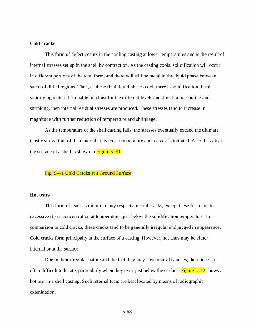
5-68
Cold cracks
This form of defect occurs in the cooling casting at lower temperatures and is the result of
internal stresses set up in the shell by contraction. As the casting cools, solidification will occur
in different portions of the total form, and there will still be metal in the liquid phase between
such solidified regions. Then, as these final liquid phases cool, there is solidification. If this
solidifying material is unable to adjust for the different levels and direction of cooling and
shrinking, then internal residual stresses are produced. These stresses tend to increase in
magnitude with further reduction of temperature and shrinkage.
As the temperature of the shell casting falls, the stresses eventually exceed the ultimate
tensile stress limit of the material at its local temperature and a crack is initiated. A cold crack at
the surface of a shell is shown in Figure 5–41.
Fig. 5–41 Cold Cracks at a Ground Surface
Hot tears
This form of tear is similar in many respects to cold cracks, except these form due to
excessive stress concentration at temperatures just below the solidification temperature. In
comparison to cold cracks, these cracks tend to be generally irregular and jagged in appearance.
Cold cracks form principally at the surface of a casting. However, hot tears may be either
internal or at the surface.
Due to their irregular nature and the fact they may have many branches, these tears are
often difficult to locate, particularly when they exist just below the surface. Figure 5–42 shows a
hot tear in a shell casting. Such internal tears are best located by means of radiographic
examination.

5-69
Fig. 5–42 Hot Tears in a Shell Casting
A phenomenon experienced on some castings is known as filamentary shrinkage cracks.
These occur at about the center wall thickness and consist of a concentration of many fine
cracks. These cracks, if not found and removed, will work outward to the surface after periods of
operation at high stress levels.
Porosity
This type of defect is the result of hot molten metal contacting damp sand and generating
steam. This steam is immediately oxidized causing the formation of hydrogen gas. If this
hydrogen gas is unable to escape through suitable vents, it will become trapped in the casting,
forming voids or gas holes that may be pin-hole size or the more typical blow holes.
To prevent this type of fault, it is important to dry the mold before pouring, and to ensure
the steel has a low hydrogen content. It is also necessary to provide adequate venting to allow the
gas that is generated during pouring to escape.
Scabs
A mixture of sand and metal exists at the surface of many castings. This mixture is
extremely hard and difficult to remove. The scab mixture is caused by a combination of hot
shrinkage of the sand and spalling—a flaking of the surface sand. Additives can be included in
the sand to improve surface binding intended to minimize the possibility of this effect.
The Upgrading of Castings

5-70
The various faults and the regions in which they can occur in a shell casting make it
necessary to develop procedures by which castings can be repair welded, or upgraded, after the
faults have been located and excavated. Because the heating cycles, through which the casting is
cycled in operation, are similar to and in some cases even more severe than its casting process, it
is necessary to develop stringent process instructions and then control the methods employed to
cover these upgrading methods. These repairs should be made by qualified welders.
One of the primary concerns with reheating a casting in preparation to undertaking
repairs is that the casting surface will form a scale. A procedure used by some manufacturers is
to paint the casting on any surface that could be affected by scaling. A paint that will maintain
surface coverage at high-temperature and minimize this effect is used.
Faults are located by NDE and the casting marked to indicate their location. These faults
are then excavated. Such excavating requires the area be explored and all the affected material
removed. Figure 5–43 shows a casting for the top half outer shell of an intermediate pressure
cylinder. Shown are the radiographic grids and chalk marks around discovered faults and the
extent of the excavations required to remove them. Surface faults in one area have been ground
away; these may or may not require repair depending upon the depth of excavation necessary to
remove them and the thickness and form of the remaining material.
Fig. 5–43 Half of a High-Pressure Nuclear Shell Casting Showing the Marked Results of
NDE and Indicating Where Excavation and Upgrading is Required.
To permit welding repairs, the casting must normally be preheated, and this preheat must
be maintained throughout the repair procedure. Typical alloy steel materials for castings require
a preheat in the range 475°F to 850°F. Such preheat can be localized or total. For high alloy
steels, total preheat is preferred to minimize the possibility of crack formation. When it is not

5-71
possible or practical to uniformly preheat the entire casing, it is necessary to surround the repair
area and heat for a distance of 12 to 16 inches on all sides of the repair. The rate of heating the
affected area should be so controlled that no part of the affected zone shall be hotter than any
other by more than about 100°F.
During the deposit of weld filler material, the preheat flame should be kept in constant
motion over the repair zone. In no case should the temperature of the casting be allowed to
exceed the nominated preheat temperature range.
During the welding process any cracks, slag inclusions, undercutting, porous crater,
granular flux, or poor fusion regions that appear on the surface of a pass must be removed before
depositing the next pass. It is often justified to make a magnetic particle examination at the
completion of some weld passes to ensure no cracks have developed. At completion of weld
deposition, the area should be allowed to cool at a rate not exceeding 100°F/hr.
At completion of the total weld repair, the rebuilt area is dressed. The casting is then heat
treated for stress relief. It is necessary to record the thermal history of any heat treatment that is
undertaken. A record of such a repair heating operation is shown in Figure 5–44. If this stress
relief operation is not complete and any internal residual stresses are not removed, there will be a
tendency for the casting to warp and distort upon machining. Such residual stresses may later
aggravate operational stresses and affect unit alignment.
Fig. 5–44 Data Produced From a Thermal Histogram for the Heat Treatment of a Turbine
Shell Half
When repairs are made to a chrome moly-vanadium casting, it is often expedient to use
chrome moly repair rod. This is necessary because of the difficulty of producing crack free welds
with electrodes containing vanadium. It is normal to check the mechanical properties of the weld

5-72
rod used for repairs, because these areas are often the cause of operating problems if mechanical
properties are not maintained.
Shell Manufacturing Tolerances
Since the casing contains high-pressure, high-temperature steam, it is necessary to ensure
all steam joints provide a good seal to prevent leakage. Leakage is efficiency degrading and
potentially dangerous. It is capable of causing serious injury or death to operations personnel.
An effective steam-tight joint is the product of two factors—a pair of flat surfaces and an
adequate bolting or clamping system that can pull the surfaces into hard close contact without
exceeding allowable stresses in the bolt or clamp. Modern manufacturing techniques allow the
horizontal shell joint to be produced by machine tools that require little or no handwork. That is,
the surface finish and flatness are normally acceptable as produced.
The inner shells for high- and intermediate-pressure cylinders should be closed to within
0.0015 in. without studs and bolts assembled. In addition, engineering blue marks will indicate
an 80% marking in high-pressure or temperature regions with a continuous band over the entire
periphery of not less than 1.0 in. wide at any point, with steam conditions above either 2200 psi
or 750°F. Below these conditions, 40% markings should be indicated with a continuous band of
0.75 in. minimum width at any point.
The requirements for outer casings are less stringent, requiring a maximum 0.006 in. gap
without bolting and 0.0015 in. with every third bolt nipped. Engineering blue marks will be 40%
overall and 80% in the region of the glands. The horizontal joint face should have a maximum
surface finish of 125 micro-inches ( _m-in.) on both inner and outer shells.
If the shells have grooves in them that will be used for locating diaphragms and are
therefore required to produce a steam seal face, these axial faces should have a finish in the range

5-73
64 to 125_m-in. If stationary blades are located directly into the casing, the finish will be
dependent upon the requirements of location and possible bending stresses that will be induced.
The Joining Of Casings Parts
There are various basic designs of casing used to contain the high-pressure high-
temperature steam. These alternate designs are selected to minimize stress in the various
components while at the same time making the casing as thermally flexible, in terms of its ability
to accept and reject heat, as possible. Such flexibility is achieved using various forms of casing.
However, these designs consist of three main types, and the difference between them is
the method employed to provide access for the rotor and then join together the various casing
halves with sufficient security they can operate without introducing excessive leakage at the
positions where the joints are made. The three principle methods of access and joining follow.
The bolted horizontal joint
The majority of high duty casings are joined at their horizontal centerline by the use of
threaded components connecting the two halves together at a flanged joint. This horizontal joint
represents a discontinuity in the thickness of the casing walls and does not have the same ability
to accept and reject heat during transient conditions. However, it does add considerable rigidity
to the casing and also helps maintain alignment because of the stiffness of this mass.
The two casing halves are joined by bolting or, more correctly in the majority of designs,
by the use of studs. These studs are screwed into the lower half and tightened by means of nuts
connecting and holding the top half casing in intimate contact with the lower half. The design
process analyzes the total load that is developed inside the casing by the high-pressure steam,
and then selects a bolting pattern sufficient to hold the casing halves in tight contact.

5-74
This clamping must be achieved without the individual studs exceeding stress levels that
would cause failure or make their useful life unacceptable in terms of the number of hours of
operation and the number of times these elements can be removed and reused.
Shown as Figure 5–45 is the bolting pattern for the half portion of a high-pressure, high-
temperature casing design employing inner and outer shells. In this layout, each bolt hole is
numbered and the bolt size required at each location defined. It is a normal practice with some
operators to maintain a log of the duty of the connecting stud at each location. They log the
number of hours of operation and the number of times the stud has been removed from service
and re-tightened.
Fig. 5–45 The Bolting Pattern for One Symmetrical Half of the Inner and Outer Half
Casing of a Fossil Unit
From this information, it is possible to predict when studs should be changed and then to
have replacement elements available for installation at a suitable outage.
An important consideration with this type of design is the rate at which heat can be conducted
through the horizontal flange to modify the temperature of the studs so they can achieve a
compatible temperature and not be over-stressed by the heating or cooling of the casing. Studs
must be able to accommodate the thermal expansion and contraction loads induced by steam
temperature changes.
Similarly, it is important that in specifying the bolting pattern there is sufficient material
remaining in the flange, in terms of the diameter and distance between hole centers, that stress
levels in the casing flange do not become excessive.
Many older designs employed grooves produced on the face of the horizontal joint, which
is designed to pass high-temperature steam between the bolt holes so the studs are able to

5-75
achieve operating temperature at a faster rate in response to major temperature changes in the
steam.
The shrink ring joint
A second design joining the casing halves is that employing shrink rings. With this
design there is a combination of studs and shrink rings used to make the joint. While the studs do
make some contribution to the total joint strength, their major function is to hold the two halves
in their correct position while the shrink rings are heated and assembled over the casing halves.
Shown as Figure 5–46 is the section through a high-pressure unit in which the inner
casing is held together by a series of nine shrink rings placed along the axial length of the casing
halves. Eight of these rings are on the downstream side of the nozzle box and one is placed on
the upstream side and above the balance piston.
Fig. 5–46 An Inner Casing With Shrink Rings
Shown in Figure 5–47 is the detail of a shrink ring dimensional requirements. Here the
casing surface is machined to a diameter of Dcc in the cold condition. In this cold condition the
shrink ring has an inner diameter of Drc. Therefore, when the ring is heated and assembled to the
casing it will upon cooling produce an interference fit of _ic=Drc-Dcc. The amount of shrink
interference fit is selected by the designer so the ring will clamp the halves but not be strained to
the extent there will be any plastic deformation of the ring.
Fig. 5–47 Details of the Shrink Fit

5-76
When steam is admitted to the unit, both the rings and casing will heat and expand. The
rings will be surrounded and attain the temperature of the steam discharge from the high-pressure
last stage blades. There will also be some small amount of heat transferred by conduction
through the casing. The internal steam temperature is higher than that of the steam surrounding
the rings.
The casing will attain an equilibrium temperature between the steam space gap and inner
wall temperature. At these higher conditions the casing will expand to Dch and the ring to Drh.
There will under these conditions be an interference fit of _ih=Dch-Drh. Again, in the hot
condition, the shrink fit will achieve an interference sufficient to maintain contact between the
two halves but not so tight as to cause plastic deformation or extensive creep of the shrink rings.
The process of heating the shrink rings enough to expand them is shown in Figure 5–48,
where a gas ring is located around the ring, heating it at a constant rate to a constant temperature
sufficient to allow assembly.
Fig. 5–48 Heating the Shrink Ring Prior to Assembly
The end-loaded rotor design (barrel construction)
The end-loaded design is shown in Figure 5–49. Here, the inner casing is a bolted
construction with the rotor and stationary blades assembled in the normal manner and bolted at
some horizontal joint. However, this inner assembly is end loaded into an outer casing that has a
close to cylindrical form. The outer cylinder is closed by the bolted attachment of an end cap,
which produces a steam tight joint with its internal pressure defined by the exhaust pressure from
the last stage blade of the section.
One significant difference with this design occurs when it is necessary to open this
section. It is necessary to disassemble any couplings to adjacent sections, then either tilt the outer
5-77
cylinder and remove the inner assembly or withdraw the inner casing through the open end. Such
disassembly will be required each time it is necessary to inspect or undertake work on the
internal cylinder or steam path. With correct training, this process can be accomplished with the
same time span of a normal maintenance outage and should not impact adversely on schedules.
Threaded Components
A major application of these components is in the connection of the joining of casing
halves. These threaded connectors used for joining the casings are intended to provide enough
contact to form a steam tight joint that is able to maintain the seal for extended periods. Such
components must also be able to be disassembled and then rejoined and able to maintain the
efficiency of the joint upon reassembly. The fasteners must be able to withstand high levels of
tensile load without failure.
To define the requirement of threaded components it is necessary to define characteristics
that establish their form and that can be used to gauge their acceptability. (Chapman 1958) These
are shown in Figure 5–50.
Fig. 5–50 Characteristics Defining the Screw Thread
Full or major diameter. For a straight thread, the major diameter is the diameter of a
coaxial cylinder that would bound the crests of an external thread or the root of an internal
thread. For a tapered thread, the major diameter is the diameter of the major core at that position.
The core or minor diameter. On a straight thread, the minor diameter is the diameter of a
coaxial cylinder that would bound the roots of an external thread and the crests of an internal
thread. On a tapered thread, the core diameter at a given position is the diameter of the minor
core at that position.

5-78
Effective pitch diameter. On a straight thread, the pitch diameter is the diameter of a
coaxial cylinder the surface of which passes through thread profiles at points that would cut them
at a width where they are one-half pitch thick. On a perfect thread, this effective diameter is the
mean of the full and core diameters.
Pitch. The distance measured parallel to the thread axis between corresponding points on
consecutive contours.
Thread angle. This is the angle subtended by thread flanks measured in an axial direction.
Crest radius. This is the radius joining adjacent flanks at the thread crest.
Root radius. This is the radius joining adjacent flanks at the thread root.
To achieve interchangeability of any threaded component, these dimensions must be the
same on both. These seven dimensions, together with flank flatness, influence the strength and
load carrying capability of the thread. Of these seven dimensions the most critical are the pitch,
thread angle, and the pitch diameter.
Forms of pitch errors
In the manufacture of a screw thread, the most critical consideration is maintaining the
correct pitch. Any excessive errors can cause uneven pressure between the flanks and affect
sharing of load between adjacent profiles. This can lead to local yielding and eventually failure at
stresses and loads well below the load carrying capability of a conforming element. There are
several sources of pitch error, the most common being introduced during the metal cutting
process due to tool or cutter wear or material stock being incorrectly clamped.
If the component is processed after the initial thread forming operation, these processes
may also introduce errors. Any process requiring the application of heat can cause errors and
such errors may be immediately apparent. However, they may also occur after a period of
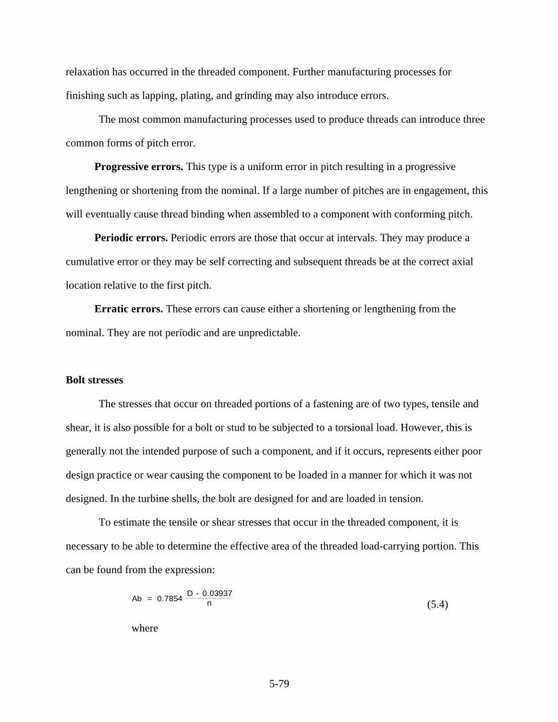
5-79
relaxation has occurred in the threaded component. Further manufacturing processes for
finishing such as lapping, plating, and grinding may also introduce errors.
The most common manufacturing processes used to produce threads can introduce three
common forms of pitch error.
Progressive errors. This type is a uniform error in pitch resulting in a progressive
lengthening or shortening from the nominal. If a large number of pitches are in engagement, this
will eventually cause thread binding when assembled to a component with conforming pitch.
Periodic errors. Periodic errors are those that occur at intervals. They may produce a
cumulative error or they may be self correcting and subsequent threads be at the correct axial
location relative to the first pitch.
Erratic errors. These errors can cause either a shortening or lengthening from the
nominal. They are not periodic and are unpredictable.
Bolt stresses
The stresses that occur on threaded portions of a fastening are of two types, tensile and
shear, it is also possible for a bolt or stud to be subjected to a torsional load. However, this is
generally not the intended purpose of such a component, and if it occurs, represents either poor
design practice or wear causing the component to be loaded in a manner for which it was not
designed. In the turbine shells, the bolt are designed for and are loaded in tension.
To estimate the tensile or shear stresses that occur in the threaded component, it is
necessary to be able to determine the effective area of the threaded load-carrying portion. This
can be found from the expression:
Ab = 0.7854 D - 0.03937
n (5.4)
where

5-80
Ab = effective area of the threaded portion
D = full or nominal diameter of threaded portion in millimeters
(mm)
n = number of threads per mm
The nominal or mean stress is a good indication of the levels within the thread elements.
It does not, however, represent the actual stresses that occur. There are two factors that act to
increase the actual stress levels above the nominal.
1. The complex form of the thread and the fact that load transmittal is through thread
teeth, which can deflect under the action of the applied axial loads.
2. The pitches of the threads are not exact. Therefore, it is not possible to ensure the
individual portions of the thread engage together to the extent the load will be shared
evenly.
These two effects can be amplified when threaded components that have operated at
high-temperature are reused, particularly if there has been any scaling during the previous
operating period. It is good practice to ensure that when such components are reused, the stud or
bolt is returned to service employing the same nut as used in the first application.
If a new stud, bolt, or nut is used in conjunction with a used component, there will
normally be some readjustment as the assembly is tightened and returned to service.
The types of failure in threaded components
There are three major types of failure that occur in the threaded components.
In the male thread at the nut face. Figure 5–51 shows a tightened nut and bolt and their
stress or load transfer lines. It is clear the nut reverses these lines and converts the tension in the
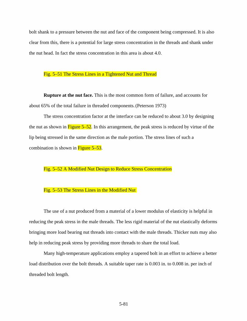
5-81
bolt shank to a pressure between the nut and face of the component being compressed. It is also
clear from this, there is a potential for large stress concentration in the threads and shank under
the nut head. In fact the stress concentration in this area is about 4.0.
Fig. 5–51 The Stress Lines in a Tightened Nut and Thread
Rupture at the nut face. This is the most common form of failure, and accounts for
about 65% of the total failure in threaded components. (Peterson 1973)
The stress concentration factor at the interface can be reduced to about 3.0 by designing
the nut as shown in Figure 5–52. In this arrangement, the peak stress is reduced by virtue of the
lip being stressed in the same direction as the male portion. The stress lines of such a
combination is shown in Figure 5–53.
Fig. 5–52 A Modified Nut Design to Reduce Stress Concentration
Fig. 5–53 The Stress Lines in the Modified Nut
The use of a nut produced from a material of a lower modulus of elasticity is helpful in
reducing the peak stress in the male threads. The less rigid material of the nut elastically deforms
bringing more load bearing nut threads into contact with the male threads. Thicker nuts may also
help in reducing peak stress by providing more threads to share the total load.
Many high-temperature applications employ a tapered bolt in an effort to achieve a better
load distribution over the bolt threads. A suitable taper rate is 0.003 in. to 0.008 in. per inch of
threaded bolt length.
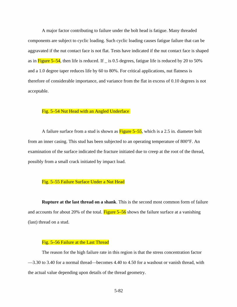
5-82
A major factor contributing to failure under the bolt head is fatigue. Many threaded
components are subject to cyclic loading. Such cyclic loading causes fatigue failure that can be
aggravated if the nut contact face is not flat. Tests have indicated if the nut contact face is shaped
as in Figure 5–54, then life is reduced. If _ is 0.5 degrees, fatigue life is reduced by 20 to 50%
and a 1.0 degree taper reduces life by 60 to 80%. For critical applications, nut flatness is
therefore of considerable importance, and variance from the flat in excess of 0.10 degrees is not
acceptable.
Fig. 5–54 Nut Head with an Angled Underface
A failure surface from a stud is shown as Figure 5–55, which is a 2.5 in. diameter bolt
from an inner casing. This stud has been subjected to an operating temperature of 800°F. An
examination of the surface indicated the fracture initiated due to creep at the root of the thread,
possibly from a small crack initiated by impact load.
Fig. 5–55 Failure Surface Under a Nut Head
Rupture at the last thread on a shank. This is the second most common form of failure
and accounts for about 20% of the total. Figure 5–56 shows the failure surface at a vanishing
(last) thread on a stud.
Fig. 5–56 Failure at the Last Thread
The reason for the high failure rate in this region is that the stress concentration factor
—3.30 to 3.40 for a normal thread—becomes 4.40 to 4.50 for a washout or vanish thread, with
the actual value depending upon details of the thread geometry.
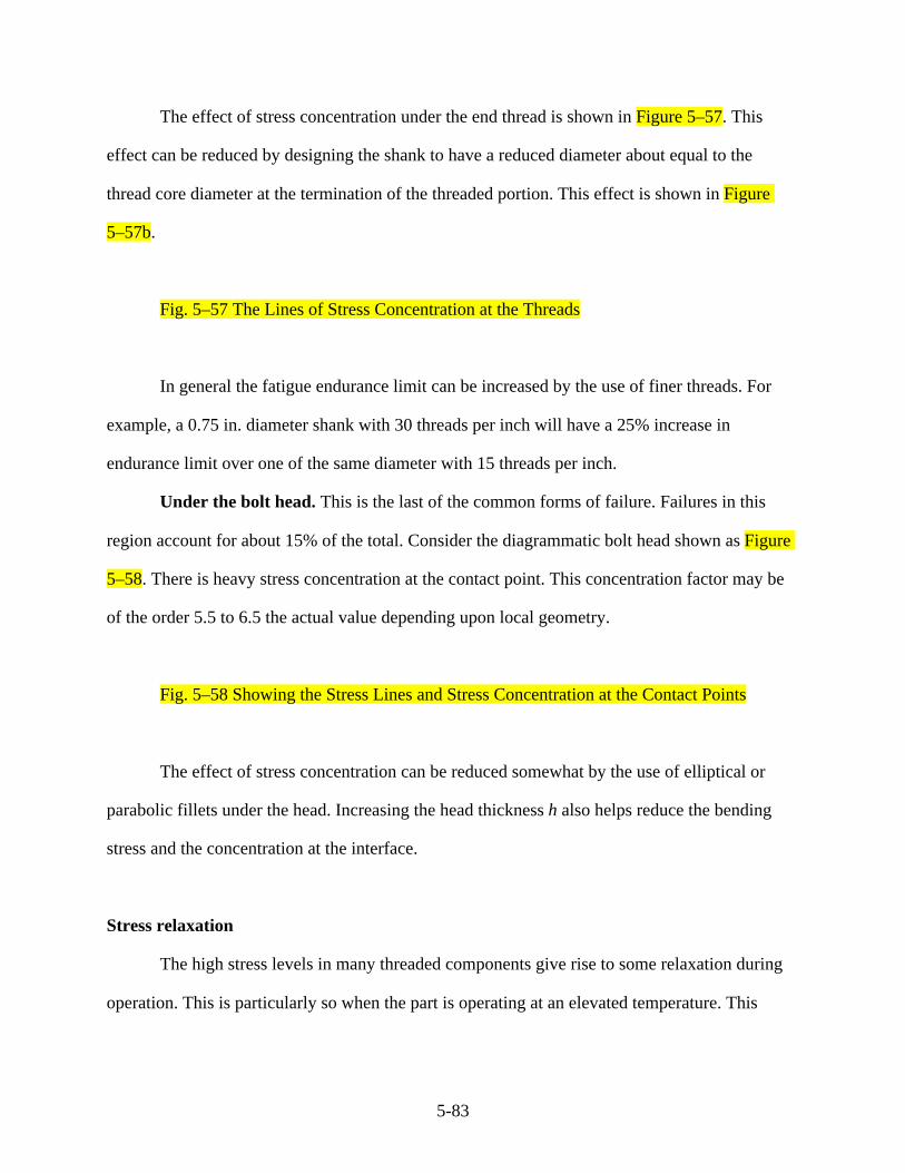
5-83
The effect of stress concentration under the end thread is shown in Figure 5–57. This
effect can be reduced by designing the shank to have a reduced diameter about equal to the
thread core diameter at the termination of the threaded portion. This effect is shown in Figure
5–57b.
Fig. 5–57 The Lines of Stress Concentration at the Threads
In general the fatigue endurance limit can be increased by the use of finer threads. For
example, a 0.75 in. diameter shank with 30 threads per inch will have a 25% increase in
endurance limit over one of the same diameter with 15 threads per inch.
Under the bolt head. This is the last of the common forms of failure. Failures in this
region account for about 15% of the total. Consider the diagrammatic bolt head shown as Figure
5–58. There is heavy stress concentration at the contact point. This concentration factor may be
of the order 5.5 to 6.5 the actual value depending upon local geometry.
Fig. 5–58 Showing the Stress Lines and Stress Concentration at the Contact Points
The effect of stress concentration can be reduced somewhat by the use of elliptical or
parabolic fillets under the head. Increasing the head thickness h also helps reduce the bending
stress and the concentration at the interface.
Stress relaxation
The high stress levels in many threaded components give rise to some relaxation during
operation. This is particularly so when the part is operating at an elevated temperature. This
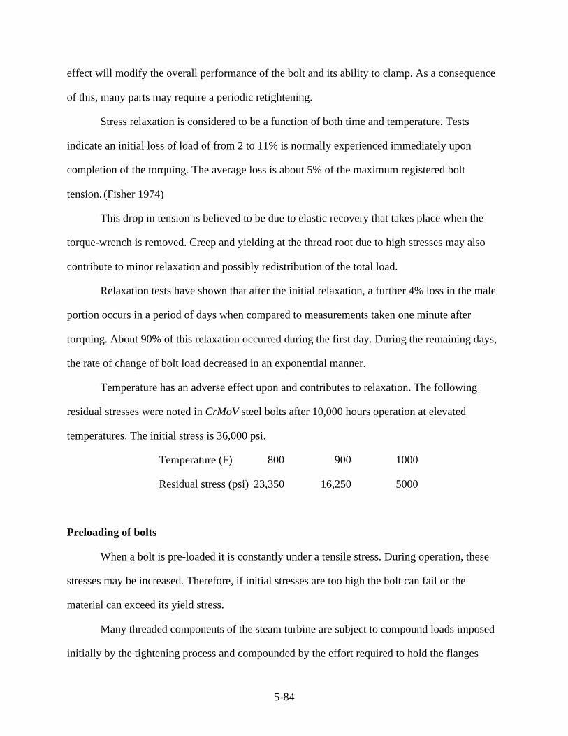
5-84
effect will modify the overall performance of the bolt and its ability to clamp. As a consequence
of this, many parts may require a periodic retightening.
Stress relaxation is considered to be a function of both time and temperature. Tests
indicate an initial loss of load of from 2 to 11% is normally experienced immediately upon
completion of the torquing. The average loss is about 5% of the maximum registered bolt
tension. (Fisher 1974)
This drop in tension is believed to be due to elastic recovery that takes place when the
torque-wrench is removed. Creep and yielding at the thread root due to high stresses may also
contribute to minor relaxation and possibly redistribution of the total load.
Relaxation tests have shown that after the initial relaxation, a further 4% loss in the male
portion occurs in a period of days when compared to measurements taken one minute after
torquing. About 90% of this relaxation occurred during the first day. During the remaining days,
the rate of change of bolt load decreased in an exponential manner.
Temperature has an adverse effect upon and contributes to relaxation. The following
residual stresses were noted in CrMoV steel bolts after 10,000 hours operation at elevated
temperatures. The initial stress is 36,000 psi.
Temperature (F) 800 900 1000
Residual stress (psi) 23,350 16,250 5000
Preloading of bolts
When a bolt is pre-loaded it is constantly under a tensile stress. During operation, these
stresses may be increased. Therefore, if initial stresses are too high the bolt can fail or the
material can exceed its yield stress.
Many threaded components of the steam turbine are subject to compound loads imposed
initially by the tightening process and compounded by the effort required to hold the flanges

5-85
together against an internal steam pressure. During operation, the bolt is also at a much higher
temperature. This temperature effect reduces the mechanical properties of the material, which
may also have imposed on it additional stresses due to heating and cooling of the turbine parts.
Consider the bolted joint shown as Figure 5–59. Assume this bolt is one of a series holding
together two components subject to internal pressure. Further, consider the effective part of the
casing flange influenced by the bolt is a portion designated as Ac.
Fig. 5–59 The Forces Induced in a Threaded Joint by Tightening and Internal Loading
Upon initial tightening, a force f, being a function of the ratio of the effective area of the
bolt Ab to the area of the flange associated with the bolt Ac, is applied to the two components.
This force f is also minimally influenced by the ratio of the moduli of elasticity of the different
materials between the bolt and flange. In Figure 5–59, the loads to the left of the centerline are
those due to bolt tightening and those to the right are those after steam loads are applied.
After initial tightening:
Extension of Bolt = f . L
Ab . Eb and, Compression of Flange =
f . LAc . Ec (5.5)
where
L = effective length of bolt or stud
Eb = modulus of elasticity of bolt material
Ec = modulus of elasticity of flange material
After the steam load is applied a new force is developed on the bolt of 'F due to internal
steam pressure P where P < f.
Therefore Extension of Bolt = F . L
Ab . Eb

5-86
and (5.6)
Decrease in Compression of Flange = ( F - P ) . L
Ac . Ec
Therefore the increase in bolt extension εb due to P is:
Increase in Extension of Bolt =
( F - f) . L
Ab . Eb
and (5.7)
Decrease in Compression of Flange = ( F - P ) . L
Ac . Ec
Equating these gives:
F = f + P
1 + Ac . Ec
Ab . Eb . L (5.8)
For the major components of a turbine subject to stress, the ratio Ac/Ab is between 5 and
10. For example, for the casings of a high-pressure fossil-fired unit the ratio is about 6. If it is
assumed that Ec/Eb =1, then:
F = f + 0.14 P (5.9)
Using this value of F, and knowing the effective area of the bolt Ab the nominal stress
can be calculated.
Considering the simplest case, extension of the bolt εb can be found from:
εb = F . L
Ab . Eb
(5.10)
Therefore, the stiffness constant Kb of the bolt can be found from Kb = F/εb.
That is Kb =
Ab . Eb1 (5.11)

5-87
If washers or other components are gripped between the bolt, then their stiffness must
also be considered. In this case the total stiffness Ks can be found from the relationship:
1Ks
= 1Kb
+ 1K1
+ 1K2
+ 1K3
. . . . 1Kn (5.12)
In equation 5.12, K1 … Kn are the stiffness constants of the other components being
compressed by the bold as it is tightened. If one of these components is a soft gasket, its stiffness
relative to the other members is usually so small that for practical purposes the others can be
neglected and only the gasket stiffness need be considered.
Reuse of high strength bolts and studs
Bolts and studs due to tightening and internal stresses during operation often have
stresses induced in them that exceed the elastic limit of the material. The repeated tightening of
high-strength bolts can, under these circumstances, be undesirable. The records of a test on
repeated tightening of such a bolt causing stresses beyond the elastic limit are shown in Figure
5–60. It is apparent the cumulative plastic deformation has caused a decrease in the bolt
deformation capacity after each succeeding tightening, which was beyond the elastic limit in
each case.
For this reason it is necessary to control the use and stress levels of all bolts and studs so
as to maintain their load carrying capability.
Fig. 5–60 The Effect of Successive Tightening on the Life of a Threaded Component
The tightening of large bolt and stud elements
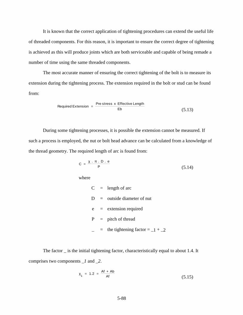
5-88
It is known that the correct application of tightening procedures can extend the useful life
of threaded components. For this reason, it is important to ensure the correct degree of tightening
is achieved as this will produce joints which are both serviceable and capable of being remade a
number of time using the same threaded components.
The most accurate manner of ensuring the correct tightening of the bolt is to measure its
extension during the tightening process. The extension required in the bolt or stud can be found
from:
Required Extension = Pre stress x Effective Length
Eb (5.13)
During some tightening processes, it is possible the extension cannot be measured. If
such a process is employed, the nut or bolt head advance can be calculated from a knowledge of
the thread geometry. The required length of arc is found from:
C = χ . π . D . e
P (5.14)
where
C = length of arc
D = outside diameter of nut
e = extension required
P = pitch of thread
_ = the tightening factor = _1 + _2
The factor _ is the initial tightening factor, characteristically equal to about 1.4. It
comprises two components _1 and _2.
χ1 = 1.2 =
Af + AbAf (5.15)

5-89
where
_2 = 0.2 = bedding down factor
Ab = effective area of bolt or stud
Af = effective area of flange
Threaded component material
For the majority of bolting materials in the steam turbine horizontal joint positions, the
material used must be selected to achieve certain mechanical properties at high-temperature and
for continual operation at high stress levels. For this reason, bolting materials are produced to
stringent specifications and normally each turbine manufacturer will have developed materials
applicable to his unit and suitable to the type of application to which the components will be put.
An important consideration with high-temperature bolting in particular is that if bolts,
studs, or nuts are replaced, it is important the replacement elements use the same class of
material. A different material could have coefficients of expansion different from the original
and this is would cause loads to be shared unevenly when there is a temperature transient in the
unit, and some elements will bear an unacceptably large portion of the total load—even
sufficient to cause their failure.
The chemical composition of typical bolting materials is given in Table 5–10 and typical
mechanical properties in Table 5–11. These tables also indicate the temperature range over
which these materials are most often used.
Table 5–10 Chemical Composition of Typical Bolt and Stud Material
Table 5–11 Mechanical Properties of Typical Bolt and Stud Material

5-90
These listed mechanical properties and chemical constituents represent the generic type
materials each manufacturer will develop specifications for their particular type of application
and will specify heat treatment to achieve the material properties required. These materials
should be free from cracks, surface flaws, or laminations. If there is any evidence of these
defects, the component manufacturer should reject this as unsuitable for the intended application.
The material specification must define the extent or degree of any defect determined by a defined
nondestructive examination.
Pipe Connection Points on the Casings
The steam entering both the high- and intermediate-pressure casings contains a
considerable amount of thermal energy with a high potential for leakage, and the joints are
exposed to considerable stresses. Such leakage can represent a considerable energy loss and a
degradation of cycle efficiency. It is also possible that certain of these joints will need to be
disassembled at maintenance outages. If there were no effort on the part of the inlet pipes to
move relative to the casings under conditions of start-up, shutdown, and during thermal
transients and no large thrust forces were developed, it would be sufficient to attach the inlet
pipes to the casing by any suitable and convenient method.
However, during warming, cooling, and condition transients, there is often a sufficient
change in the rates of expansion between the pipes and casing that there is relative growth
between them sufficient to cause a force in the pipes that can move the turbine and disturb the
alignment between stationary and rotating parts. Therefore, provision must be made to
accommodate this movement.
Some of this potential movement is accommodated by the methods used to locate and
hang the pipes, while other connections must be designed to allow relative movement at the
piping/casing interface sufficient to limit leakage and also to allow disassembly.

5-91
There are several methods of conveniently introducing steam into or removing it from the
casing with each providing flexibility and minimizing steam leakage losses. There are four basic
systems that may be used individually or in combination to allow the pipes to connect to and if
necessary pass through the outer casing, then enter and connect to the inner casing or nozzle box
sufficient to allow the steam to enter the first stage stationary blade row. These methods are
discussed next.
Bolted connection
The simplest form is that in which a flanged and bolted connection is made. This type of
connection is used for lower rating units where the initial steam pressures and temperatures can
be classified as moderate. Such a connection could not be used for modern high steam condition
units. However, such a connection can still be used effectively for steam extraction points.
When such flanged connections are made, the flanges are arranged so the inlet pipes can
be disconnected to allow removal of the casing. This requires a second connection be made
outside the bounds of the casing to allow vertical withdrawal as seen in Figure 5–61.
Fig. 5–61 The Lifting Gap Required to Remove the Top Half Outer Casing
In such a system, it is necessary to ensure there is sufficient flexibility in the pipe system,
and the pipe hangers are maintained to retain piping flexibility.
Upper half weld
A common type of connection made to many higher rating units in the top half is the
welded form. This connection is used extensively in both high- and intermediate-pressure
sections. To allow connection, the casing is cast with stubs integral with the main shell casting.
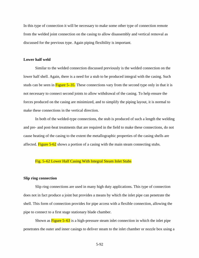
5-92
In this type of connection it will be necessary to make some other type of connection remote
from the welded joint connection on the casing to allow disassembly and vertical removal as
discussed for the previous type. Again piping flexibility is important.
Lower half weld
Similar to the welded connection discussed previously is the welded connection on the
lower half shell. Again, there is a need for a stub to be produced integral with the casing. Such
studs can be seen in Figure 5–35. These connections vary from the second type only in that it is
not necessary to connect second joints to allow withdrawal of the casing. To help ensure the
forces produced on the casing are minimized, and to simplify the piping layout, it is normal to
make these connections in the vertical direction.
In both of the welded-type connections, the stub is produced of such a length the welding
and pre- and post-heat treatments that are required in the field to make these connections, do not
cause heating of the casing to the extent the metallographic properties of the casing shells are
affected. Figure 5-62 shows a portion of a casing with the main steam connecting stubs.
Fig. 5–62 Lower Half Casing With Integral Steam Inlet Stubs
Slip ring connection
Slip ring connections are used in many high duty applications. This type of connection
does not in fact produce a joint but provides a means by which the inlet pipe can penetrate the
shell. This form of connection provides for pipe access with a flexible connection, allowing the
pipe to connect to a first stage stationary blade chamber.
Shown as Figure 5–63 is a high-pressure steam inlet connection in which the inlet pipe
penetrates the outer and inner casings to deliver steam to the inlet chamber or nozzle box using a

5-93
combination of welded (inner pipe piece) and bolted connections to the outer casing and a slip
ring passage through the inner shell to the nozzle box.
Fig. 5–63 A High-Pressure Inlet Employing a Flexible Connection With Piston Rings
Shown in greater detail in Figure 5–64 is a portion of a slip ring system. Here the
connection is made through a guide bush with the aid of slip rings. The guide bush and slip rings
are normally produced from Stellite or a similar resistant material because of the high service in
this region and the need to minimize wear. The number of rings used depends upon the pressure
differential across the inner casing at the point of entry. The slip rings provides a precision seal,
minimizing leakage by causing successive throttlings across each ring.
Fig. 5–64 The Slip Ring System
To provide the degree of flexibility required in the inlet region, the system must provide
for relative movement between the inlet pipe, the casing, and the nozzle box or steam chamber.
To ensure this flexibility, there must be the ability for relative movement built into the ring
system. Consider the portion of the slip ring shown in Figure 5–64 where the steam enters and
flows down the pipe.
The steam, because of the pressure differential, will attempt to follow a leakage path past
the rings shown as t-t under the differential pressure dp across the rings. Each of the rings will
provides a seal surface s. There are, therefore, parallel leakage paths along each ring face as
shown. The clearance Ct allows the pipe to move in a direction transverse to its axis, and at the
same time, maintain a seal on the face s. For assembly Ct must be greater than q, which is the
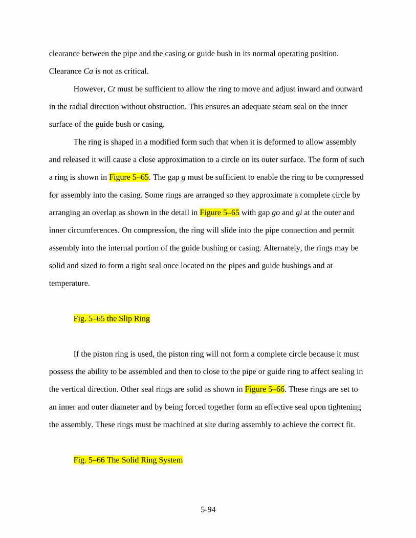
5-94
clearance between the pipe and the casing or guide bush in its normal operating position.
Clearance Ca is not as critical.
However, Ct must be sufficient to allow the ring to move and adjust inward and outward
in the radial direction without obstruction. This ensures an adequate steam seal on the inner
surface of the guide bush or casing.
The ring is shaped in a modified form such that when it is deformed to allow assembly
and released it will cause a close approximation to a circle on its outer surface. The form of such
a ring is shown in Figure 5–65. The gap g must be sufficient to enable the ring to be compressed
for assembly into the casing. Some rings are arranged so they approximate a complete circle by
arranging an overlap as shown in the detail in Figure 5–65 with gap go and gi at the outer and
inner circumferences. On compression, the ring will slide into the pipe connection and permit
assembly into the internal portion of the guide bushing or casing. Alternately, the rings may be
solid and sized to form a tight seal once located on the pipes and guide bushings and at
temperature.
Fig. 5–65 the Slip Ring
If the piston ring is used, the piston ring will not form a complete circle because it must
possess the ability to be assembled and then to close to the pipe or guide ring to affect sealing in
the vertical direction. Other seal rings are solid as shown in Figure 5–66. These rings are set to
an inner and outer diameter and by being forced together form an effective seal upon tightening
the assembly. These rings must be machined at site during assembly to achieve the correct fit.
Fig. 5–66 The Solid Ring System
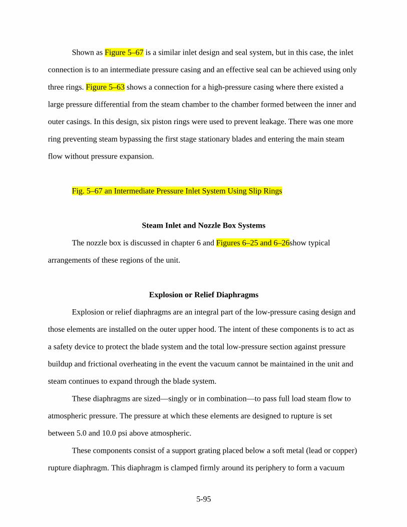
5-95
Shown as Figure 5–67 is a similar inlet design and seal system, but in this case, the inlet
connection is to an intermediate pressure casing and an effective seal can be achieved using only
three rings. Figure 5–63 shows a connection for a high-pressure casing where there existed a
large pressure differential from the steam chamber to the chamber formed between the inner and
outer casings. In this design, six piston rings were used to prevent leakage. There was one more
ring preventing steam bypassing the first stage stationary blades and entering the main steam
flow without pressure expansion.
Fig. 5–67 an Intermediate Pressure Inlet System Using Slip Rings
Steam Inlet and Nozzle Box Systems
The nozzle box is discussed in chapter 6 and Figures 6–25 and 6–26show typical
arrangements of these regions of the unit.
Explosion or Relief Diaphragms
Explosion or relief diaphragms are an integral part of the low-pressure casing design and
those elements are installed on the outer upper hood. The intent of these components is to act as
a safety device to protect the blade system and the total low-pressure section against pressure
buildup and frictional overheating in the event the vacuum cannot be maintained in the unit and
steam continues to expand through the blade system.
These diaphragms are sized—singly or in combination—to pass full load steam flow to
atmospheric pressure. The pressure at which these elements are designed to rupture is set
between 5.0 and 10.0 psi above atmospheric.
These components consist of a support grating placed below a soft metal (lead or copper)
rupture diaphragm. This diaphragm is clamped firmly around its periphery to form a vacuum
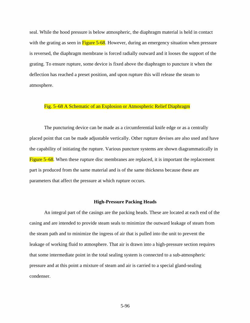
5-96
seal. While the hood pressure is below atmospheric, the diaphragm material is held in contact
with the grating as seen in Figure 5-68. However, during an emergency situation when pressure
is reversed, the diaphragm membrane is forced radially outward and it looses the support of the
grating. To ensure rupture, some device is fixed above the diaphragm to puncture it when the
deflection has reached a preset position, and upon rupture this will release the steam to
atmosphere.
Fig. 5–68 A Schematic of an Explosion or Atmospheric Relief Diaphragm
The puncturing device can be made as a circumferential knife edge or as a centrally
placed point that can be made adjustable vertically. Other rupture devises are also used and have
the capability of initiating the rupture. Various puncture systems are shown diagrammatically in
Figure 5–68. When these rupture disc membranes are replaced, it is important the replacement
part is produced from the same material and is of the same thickness because these are
parameters that affect the pressure at which rupture occurs.
High-Pressure Packing Heads
An integral part of the casings are the packing heads. These are located at each end of the
casing and are intended to provide steam seals to minimize the outward leakage of steam from
the steam path and to minimize the ingress of air that is pulled into the unit to prevent the
leakage of working fluid to atmosphere. That air is drawn into a high-pressure section requires
that some intermediate point in the total sealing system is connected to a sub-atmospheric
pressure and at this point a mixture of steam and air is carried to a special gland-sealing
condenser.
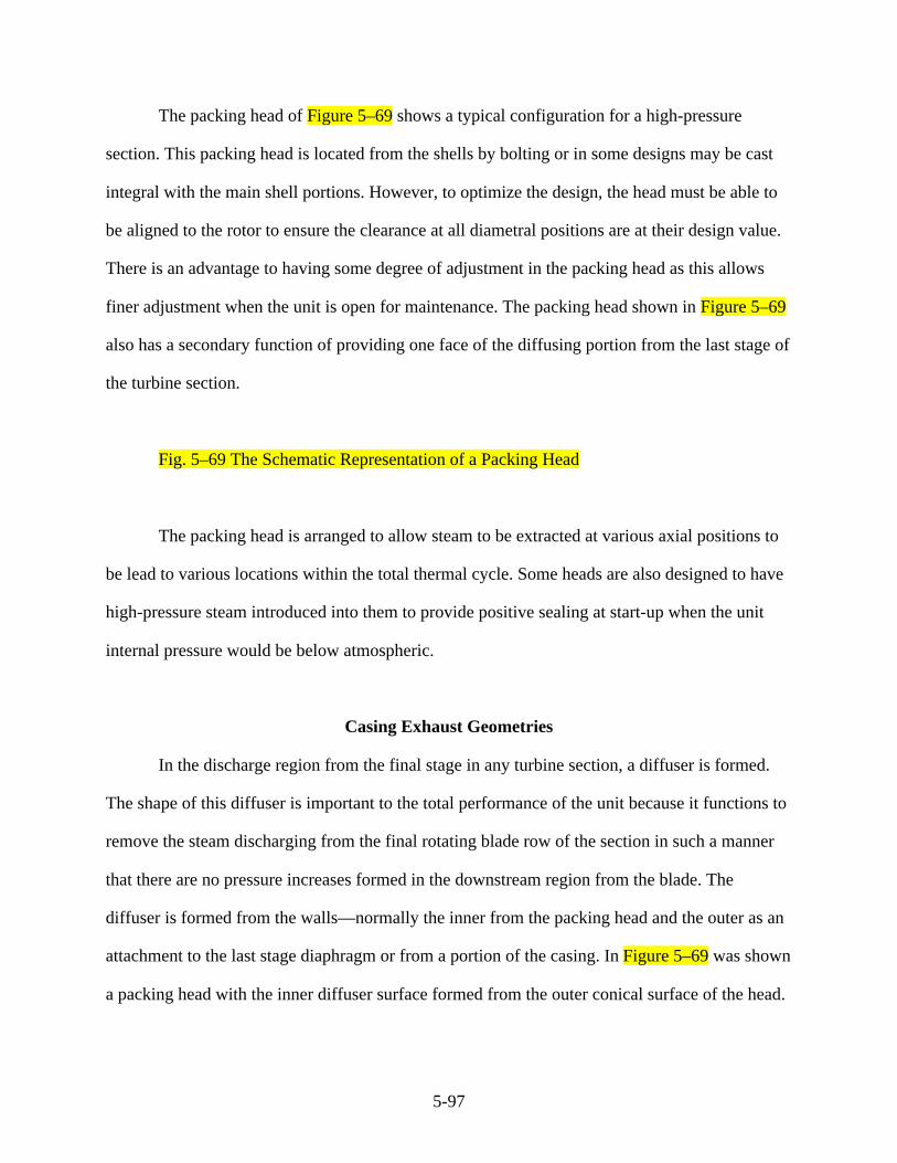
5-97
The packing head of Figure 5–69 shows a typical configuration for a high-pressure
section. This packing head is located from the shells by bolting or in some designs may be cast
integral with the main shell portions. However, to optimize the design, the head must be able to
be aligned to the rotor to ensure the clearance at all diametral positions are at their design value.
There is an advantage to having some degree of adjustment in the packing head as this allows
finer adjustment when the unit is open for maintenance. The packing head shown in Figure 5–69
also has a secondary function of providing one face of the diffusing portion from the last stage of
the turbine section.
Fig. 5–69 The Schematic Representation of a Packing Head
The packing head is arranged to allow steam to be extracted at various axial positions to
be lead to various locations within the total thermal cycle. Some heads are also designed to have
high-pressure steam introduced into them to provide positive sealing at start-up when the unit
internal pressure would be below atmospheric.
Casing Exhaust Geometries
In the discharge region from the final stage in any turbine section, a diffuser is formed.
The shape of this diffuser is important to the total performance of the unit because it functions to
remove the steam discharging from the final rotating blade row of the section in such a manner
that there are no pressure increases formed in the downstream region from the blade. The
diffuser is formed from the walls—normally the inner from the packing head and the outer as an
attachment to the last stage diaphragm or from a portion of the casing. In Figure 5–69 was shown
a packing head with the inner diffuser surface formed from the outer conical surface of the head.

5-98
The form of the diffuser is selected to allow the steam to expand through the passage
formed, without causing any pressure increase. In many designs, it is possible to produce a
pressure gradient through the diffuser that is decreasing from inlet to discharge. There are
significant gains to be made with correctly designed diffusers, and their form will reduce fuel
consumption by significant amounts. This is discussed in more detail in “CFD Puts New Spin on
Turbine Hoods,” in RI Fossil Plant News, Spring 1998.
Shown as Figure 5–70 is the diffuser portion from a typical reheat or low-pressure
section. Here the inner surface s-r is formed by the packing head and the outer surface t-u by
some surface provided from the major stationary components. It can be seen that there is a
gradual increase in flow area and that with a minimal or negligible increase in steam specific
volume will cause a reduction in steam velocity as it flows through the diffuser section of the
unit.
Fig. 5–70 A High-Pressure Section Diffuser, Showing the Variation of Flow Area Along
the Length of the Diffuser Portion
The steam energy expended in the low-pressure section represents a major portion of the
total energy available in the fluid, and in many unit designs, the last stage produces as much as
10% of the total power developed in the turbine. For this reason, the design parameters around
this last stage become critical to the total performance of the unit. The axial component of the
steam velocity leaving the last stage will normally be in the range of 500 to 1500 ft/sec and in
some designs may even be larger. Therefore, this indicates the criticality of the exit region of the
last stage where relatively minor changes in geometry can have a significant impact on
performance.
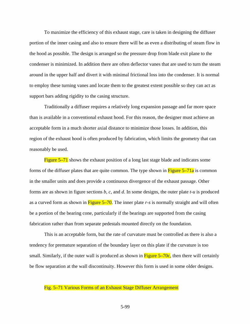
5-99
To maximize the efficiency of this exhaust stage, care is taken in designing the diffuser
portion of the inner casing and also to ensure there will be as even a distributing of steam flow in
the hood as possible. The design is arranged so the pressure drop from blade exit plane to the
condenser is minimized. In addition there are often deflector vanes that are used to turn the steam
around in the upper half and divert it with minimal frictional loss into the condenser. It is normal
to employ these turning vanes and locate them to the greatest extent possible so they can act as
support bars adding rigidity to the casing structure.
Traditionally a diffuser requires a relatively long expansion passage and far more space
than is available in a conventional exhaust hood. For this reason, the designer must achieve an
acceptable form in a much shorter axial distance to minimize those losses. In addition, this
region of the exhaust hood is often produced by fabrication, which limits the geometry that can
reasonably be used.
Figure 5–71 shows the exhaust position of a long last stage blade and indicates some
forms of the diffuser plates that are quite common. The type shown in Figure 5–71a is common
in the smaller units and does provide a continuous divergence of the exhaust passage. Other
forms are as shown in figure sections b, c, and d. In some designs, the outer plate t-u is produced
as a curved form as shown in Figure 5–70. The inner plate r-s is normally straight and will often
be a portion of the bearing cone, particularly if the bearings are supported from the casing
fabrication rather than from separate pedestals mounted directly on the foundation.
This is an acceptable form, but the rate of curvature must be controlled as there is also a
tendency for premature separation of the boundary layer on this plate if the curvature is too
small. Similarly, if the outer wall is produced as shown in Figure 5–70c, then there will certainly
be flow separation at the wall discontinuity. However this form is used in some older designs.
Fig. 5–71 Various Forms of an Exhaust Stage Diffuser Arrangement

5-100
5-101
References and Bibliography
ASME Specification A284-70a. “Low and Intermediate Tensile Strength Carbon Plate for
Machine Parts and General Construction.”
AWS, AWS Standard Welding Symbols A 2.0-68.
Blodgett, O.W. Design of Welded Structures. Cleveland, Ohio: The James F. Lincoln Arc
Welding Foundation, June 1956.
“CFD Puts New Spin on Turbine Hoods.” RI Fossil Plant News, Spring 1998, Issue 40.
Chapman, W.A.J. Workshop Technology Part III. London: Edward Arnold Ltd., 1958.
Clymer, F. “Quality Control as Applied to Steam Turbine Castings.” Intitution of Mechanical
Engineers (I. Mech. E.) Ontario Committee, 1968.
Curran, R.M. and D.P. Timo. “Heat Treated Steel for Elevated Temperature Service in Modern
Large Steam Turbines.” Presented at the Symposium on Heat Treated Steels for Elevated
Temperature Service, Mechanical Engineering Conference, Louisiana, 1964.
Fisher, J.W. Guide to Design Criteria for Bolted and Riveted Joints. 1974.
Hummer, J and J. Drahy. “The Skoda 200 MW Steam Turbine.” Czechoslovak Heavy Industry,
February 1964.
Jackson, R.L., S.A.B. Coulter, and R. Sheppard. “Importance of Matching Steam Temperatures
with Metal Temperatures During Starting of Large Steam Turbines.” Trans. American
Society of Mechanical Engineers (ASME), Vol. 79, 1957.
Kent, R.P. “Some Aspects of Metallurgical Research and Development Applied to Large Steam
Turbines.” C.A. Parsons Journal, General Electric Publication, Christmas, 1964.
Lincoln Electric Company, The Procedures Handbook of Arc Welding: Twelfth Edition, The
Lincoln Electric Company, June 1973.
Paolini, N.A. Practical Applications of Welding Technology. Canadian Welding Development
Institute.

5-102
Peterson, R.E. Stress Concentration Factors. Wiley-Interscience Publications, New York, 1973.
Rogers, J.A. and R.C. Brewer. “Faults in Cast Components for High-pressure, High-temperature
Service.” I. Mech. E. Proc. 1964–65, Vol. 179, Pt. 1, No. 2.
Rollason, E.C. Metallurgy for Engineers. London: Edward Arnold Limited, London, 1956.
Tavernelli, T.F. and L.F. Coffin. “Experimental Support for Generalised Equation Predicting
Low Cycle Fatigue.” ASME Paper No. 61-WA-199, 1961.
Timo. D.P. “Typical Fatigue Failure Problems and Fixes in Large Steam Turbines.” A.S.M.
Conference on Fatigue, Boston 1970.
Watson, H. “Factors in the Design of Large Steam Turbines for High Availability.” Institute of
Mechanical Engineers Convention on Steam Plant Availability. Proc. I. Mech., E. 1964–5.
“What’s Ailing That Weld?” Welding Journal, August 1997.