and driveways fences miscellaneous structures and archeological remains environmental considerations...
TRANSCRIPT
" .. ... . .... ..
Solomon Claybaugh Young Architects Inc .
I I ( 1 t
j
• ; 'J
'J

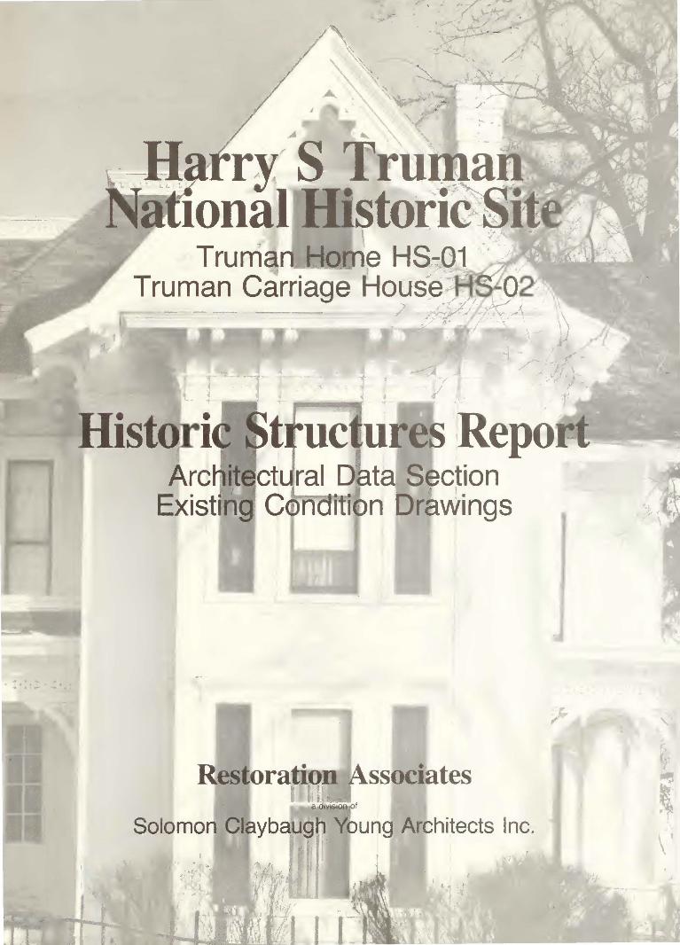
HARRY S TRUMAN NATIONAL HISTORIC SITE
INDEPENDENCE, MISSOURI
Historic Structures Report
by:
Restoration Associates a division of Solomon Claybaugh Young Architects Inc. 20 West 9th Street Kansas City, Missouri
for:
Office of Planning & Resource Preservation Division of Cultural Resources Management National Park Service United States Department of the Interior Omaha, Nebraska
Recommended:
Approved:
64105
'"f-).'7- '67 Date
Date ' I
I I
! l '
CREDITS
Report prepared by: Restoration Associates
Principal-in-Charge: Robert J. Claybaugh, AIA Architectural Historian and Writer: Cydney Millstein Historical Architect: Douglas R. Wasama, AIA Project Architect: E. Eugene Young, AIA
Site Survey: Tuttle-Ayres-Woodward Co.
Mechanical/Electrical Consultant: Associated Engineering Consultants
Project Engineer: Tony Hitchcock
Structural Consultant: Harper & Kerr
Project Engineer: Gary Harper
Photography (Primary Exterior Photos): Zoom Studios
ii

ACKNOWLEDGEMENTS
We would like to express our appreciation to the following people who helped in the development of this project.
Alan O'Bright Ron Cockrell Steve Harrison Lisa Houston Tom Richter Pauline Testerman Janet Bruce Pat Hininger Carol Simons
iii
CONTENTS
I.
II.
List of Illustrations Index of Drawings
BUILDING CHRONOLOGY -- TRUMAN HOME (HS-01) Notes Illustrations Building Chronology Drawings (Sheets 1-3)
EXISTING CONDITIONS -- TRUMAN HOME (HS-01) Introduction Architecture and Engineering Team Scope of National Park Service Work Building Description and Analysis Landscape Topography Vegetation Walkways and Driveways Fences Miscellaneous Structures and Archeological Remains Environmental Considerations Underground Utilities Foundation First Floor Framing and Condition First Floor General Condition Porches
Second Floor Sleeping Porch Second Floor Framing a!'d Condition Attic Floor Framing and Condition Roof Framing and Conditions
Attic Roof Attic Dormers Kitchen Wing Roof Roofing Materials
Wall System Framing Exterior and Interior Stair Systems Exterior Envelope Windows Doors Exterior Finishes Interior Finishes Plumbing Services and Systems Waste and Vent System
iv
viii x
1 11 13
27 27 27 28 29 31 31 31 32 33 33 34 35 35 37 43 46 49 so 53 S4 S4 SS S6 56 S7 S9 60 60 62 62 64 67 68

CONTENTS -- 2
Gas System Historic (c. 1885) System Existing System
Heating System Historic Ductwork
Gas Yard Lamp and Interior Gas Fixtures Ventilation System Air-Conditioning System
Historic Non-Historic
Electrical Service and Systems Lightning Protection System Security and Fire Detection Systems Communication Systems Notes Illustrations Existing Condition Drawings (Sheets 1-55)
III. EXISTING CONDITIONS -- TRUMAN CARRIAGE HOUSE (HS-02) Introduction and Description Topography Foundation Wall Foundation Sills Garage Floor Floor/Ceiling System Framing Roof System Framing Roofing Materials Wall System Framing Exterior Envelope and Finishes Windoli'S Doors Interior Finishes Electrical Service and Systems Security Systems
Historic Security System Notes Illustrations Existing Condition Drawings (Sheets 1-11)
v
68 68 69 69 69 70 71 72 72 72 73 73 75 76 77 79 83
97 97 97 98 99
100 100 101 102 103 104 106 108 108 109 110 110 111 113
CONTENTS -- 3
IV. DESIGN DEVELOPMENT AND RECOMMENDATIONS Truman Home (HS-01)
Introduction Recommendations for Restoration Work
Topography Vegetation Pavements Foundation Roof Floors Plaster Tile Temperature and Humidity Control Lincrusta Plumbing System Electrical System Heating and Cooling System
Evaluation of Visitor Impact Recommendations (Vistor Impact)
Evaluation of Energy Conservation Measures Evaluation of Handicapped Access
Permanent Ramp Portable Ramp Stair Trac Wheelchair Lift
Recommendations for Handicapped Access Stair Trac Portable Ramp Wheelchair Lift
Recommendations for Further Research Historical Research Floor/Ceiling System Framing Wall Structural Systems Wallpaper
Investigation of Structure of Stair to Second Floor Site Archeology at Foundation Walls
Cost Estimate
vi
119 119 120 120 121 121 121 121 122 122 124 124 124 124 125 126 126 127 128 128 128 129 129 130 130 130 131 131 132 132 132 132 133 134 134 135

CONTENTS -- 4
Truman Carriage House (HS-02) Introduction Recommendations for Restoration Work
Topography Vegetation Foundation and Structural Posts Wall System Framing Roof Systems Floor/Ceiling Structural Systems Building Envelope Exterior/Interior Finishes Security System
Recommendations for Further Research Cost Estimate Notes
APPENDICES
137 137 137 138 138 139 139 140 140 142 142 142 143 145
A. National Park Service Reports and Fabric Analysis 147 B. Chronological List of Work Completed by the National 149
Park Service C. Anticipated Work by the National Park Service 151 D. List of Site Structures 153 E. Maps 159 F. Wall Systems. Excerpts from "Physical Investigation
Report, Truman Home," July 24-26, 1984 171 G. Post Base Conditions. Excerpts from "Physical
Investigation Report and Treatment Proposal, Truman Carriage House," April, 1986 185
H. Munsell Color Chart 199
BIBLIOGRAPHY 201
vii
LIST OF ILLUSTRATIONS
Fig. Title
1.1 Bird's Eye View of Independence. A. Ruger, 1868. Detail. Credit: Jackson County Historical Soceity
1.2 Truman Home. Construction detail of connection between main house and kitchen wing. Credit: Doug Wasama
1.3 Residence of George P. Gates. Independence dence, Missouri, January 2, 1886. Credit: Library (HSTL)
Sentinel, IndepenHarry S Truman
1.4 Truman Home, c. 1900. West elevation (looking east). One of a series of the earliest extant photographs of the structure. Note the absence of the roof line decorative grillwork as shown in the 1886 Independence Sentinel. Credit: HSTL
1.5 Truman Home, southeast). balustrade.
c. 1905. Porch, northwest elevation (looking Bess Wallace Truman sitting on the original porch Credit: HSTL
1.6 Truman Home, c. 1900. Southeast elevation (looking northeast). Two unidentified men standing in front of the rear porch that was converted to a bathroom c. 1907-1910. Credit: HSTL
1.7 Truman Home, c. 1940. East elevation (looking west). The 1920's pergola is pictured to the right of the rear porch. Credit: HSTL
1.8 Truman Home, July 11, 1944, West elevation (looking east).
1.9
1.10
Before 1945 renovation. Credit: HSTL
Truman Home, July 22, 1944, Detail showing condition of Credit: HSTL
Truman Home, May 21, 1945, Workers begin renovation.
West elevation (looking southeast). home prior to 1945 renovation.
West elevation (looking southeast). Credit: HSTL
1.11 Truman Home, June 27, 1945, West elevation (looking east). After 1945 renovation. Credit: HSTL
viii
LIST OF ILLUSTRATIONS -- 2
Title
2.1 Truman Home, February-March 1986. West elevation (looking east). Credit: Zoom Studios
2.2 Truman Home, February-March 1986. North elevation (looking south). Credit: Zoom Studios
2.3 Truman Home, February-March 1986. East elevation (looking west). Credit: Zoom Studios
2.4 Truman Home, February-March 1986. South elevation (looking north). Credit: Zoom Studios
2.5 Topographical Survey Site Map, Harry S Truman National Historic Site. May 27, 1986, revised July 2, 1986. Credit: The Tuttle-Ayers-Woodward Company
2.6 Brick Nogging, Truman Home. North elevation, July, 1984. Credit: National Park Service, Midwest Region
3.1 Truman Carriage House, Fall 1985. North elevation (looking south). Credit: Zoom Studios
3.2 Truman Carriage House, Fall 1985. South elevation (looking north). Credit: Zoom Studios
3.3 Truman Carriage House, Fall 1985. East elevation (looking west). Credit: Zoom Studios
3.4 Truman Carriage House, Fall 1985. West elevation (looking east). Credit: Zoom Studios
3.5 Sill Beam at Post #17, Truman Carriage House. December 1985. West elevation. Credit: National Park Service, Midwest Region
ix
INDEX OF DRAWINGS
Building Chronology - Truman Home (HS-01)
No. Title
1. 1867 - 1885
2. 1885 - 1910
3. 1910 - 1982
Existing Conditions - Truman Home (HS-01)
No. Title
1. Title Sheet
2. General Information
3. Topographical Site Plan
4. Foundation/Basement Plan
5. First Floor Plan
6. Second Floor Plan
7. Attic Floor Plan
8. Roof Plan
9. First Floor Framing Plan
10. Second Floor Framing Plan
11. Attic Floor Framing Plan
12. Roof Framing Plan & Widows Walk Rafter Plan
13. Exterior Elevation - North
14. Exterior Elevation - West
x
I --~~~~~~~~~~~~~~~~~~~~~~~~~~~-·~
INDEX OF DRAWINGS -- 2
Existing Conditions - Truman Home (HS-01) (continued)
No. Title
15. Exterior Elevation - South
16. Exterior Elevaton - East
17. Building Section looking North through Living Room and Stairwell
18. Building Section looking West through Gates Bedroom and Dining Room
19. Building Section looking South through Kitchen, Library and Music Room
20. Building Section looking East through Music Room, Foyer and Living Room
21. Interior Elevation Basement
22. Interior Elevation First Floor
23. Interior Elevation First Floor
24. Interior Elevation First Floor
25. Interior Elevation Second Floor
26. Interior Elevation Second Floor
27. Interior Elevation Second Floor
28. Interior Elevation Attic
29. Detail Section through North Wall
30. Detail Section through South Wall
31. Framing Details
xi
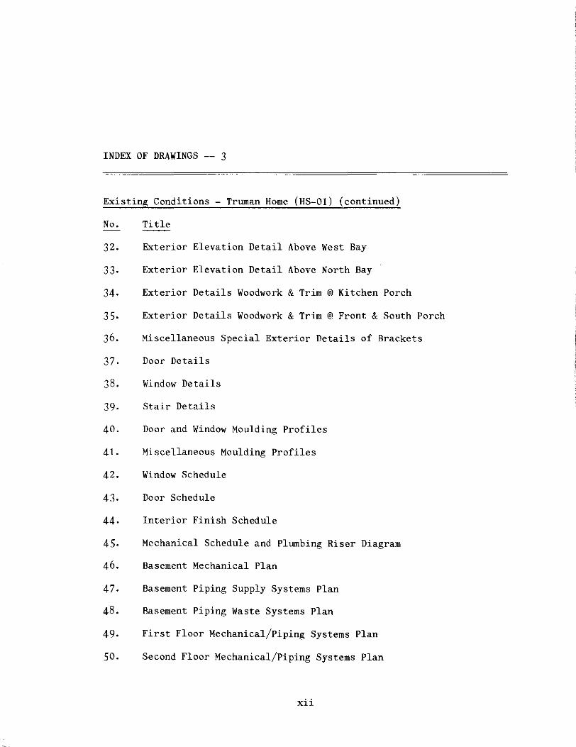
INDEX OF DRAWINGS -- 3
Existing Conditions - Truman Home (HS-01) (continued)
No. Title
32. Exterior Elevation Detail Above West Bay
33. Exterior Elevation Detail Above North Bay
34. Exterior Details Woodwork & Trim @ Kitchen Porch
35. Exterior Details Woodwork & Trim @ Front & South Porch
36. Miscellaneous Special Exterior Details of Brackets
37. Door Details
38. Window Details
39. Stair Details
40. Door and Window Moulding Profiles
41. Miscellaneous Moulding Profiles
42. Window Schedule
43. Door Schedule
44. Interior Finish Schedule
45. Mechanical Schedule and Plumbing Riser Diagram
46. Basement Mechanical Plan
47. Basement Piping Supply Systems Plan
48. Basement Piping Waste Systems Plan
49. First Floor Mechanical/Piping Systems Plan
50. Second Floor Mechanical/Piping Systems Plan
xii

INDEX OF DRAWINGS -- 4
Existing Conditions - Truman Home (HS-01) (continued)
No. Title
51. Attic Floor Mechanical/Piping Systems Plan
52. Basement Electrical Systems
53, First Floor Electrical Systems
54, Second Floor Electrical Systems
55, Attic Floor Electrical Systems
Existing Conditions - Truman Carriage House (HS-02)
No. Title
1. Footing/Foundation Plan, Ground Floor Plan & Loft Plan
2. Roof Plan
3. Loft Floor Framing & Roof Framing Plan
4. Exterior Elevation East & West
5. Exterior Elevation South
6. Exterior Elevation North
7. Longitudinal Section looking South
8. Transverse Section looking East
9. Interior Elevation Ground Floor
10. Interior Elevation Loft Floor
11. Framing & Exterior Details
xiii
I. Building Chronology -- Truman Home (HS-01)
The Truman Home (HS-01) and Truman Carriage House (HS-02), 219 North
Delaware Street, Independence, Missouri, are on lots 2 and 3 of James F.
Moore's Addition. Moore's Addition was platted on September 29, 1847.
Soon after the 1849 town incorporation, Moore's Addition was included in
1 Independence. (See Appendix E (e), Map of Independence, 1877.)
James F. Moore, an Independence merchant, purchased approximately forty
acres and a portion of Town Lot 38 from Cornelius Davy on August 3,
2 1839, for $5,000.00. A year prior to the 1849 incorporation of
Independence, Moore, through power of attorney, sold off his property,
lot by lot. 3
On August 28, 1848, lots 2 through 6, 8 and 16 through 18 of James F.
Moore's Addition were sold to William B. Hay. The nine lots were
purchased for $800.00.4
In August of 1850, shortly after Hay's business failed, Jackson County
Clerk Samuel A. Lucas "issued a writ of fieri facias against William Hay
to compensate Hay's creditors."5 The writ authorized Sheriff George W.
Buchanan to advertise Hay's property in advance of selling it at public
auction. On September 11, 1850, lots 2 and 3 of Moore's Addition were
sold to Independence Mayor Jonathan R. Palmer for $220.0o. 6
- 1 -
Like Hay, Jonathan Palmer suffered from debts. Three weeks after the
auction, on October 2, Palmer mortgaged all his property to John B.
Slaughter for a $6,000.00 bond. After Palmer defaulted on the bond,
Slaughter, a merchant and Palmer's successor as mayor, received legal
title to lots 2 through S of Moore's Addition. After the Slaughter
family moved to St. Louis, they sold their property to James T. Thorton
and Francis Hord for $500.00 on February 2, 1857. 7
Through public auctions and trustee's deeds, lots 2 and 3 changed hands
a number of times because of debt-plagued property owners.
James T. and Mary H. Thorton, on November 29, 1859, deeded lots 2 and 3
to Peter Gastel for $350.00. In debt, the Gastels were forced into a
three party trustee's deed, with William Chrisman as middleman.
Chrisman had paid the Gastels one dollar for lots 2 and 3 to hold in
trust for one year (until November 20, 1861). If the debt went unpaid,
Chrisman was authorized to sell lots 2 and 3 at public auction. 8
Interrupted by the events of the Civil War, William Chrisman was pre
vented from carrying out the provisions of the 1860s trustee's deed,
until September 26, 1866, when lots 2 and 3 were sold at auction to
James G. English for $425.00. 9
Then, through a series of complex and shrewd business transactions,
George P. Gates (the grandfather of Bess Wallace Truman), a recent
- 2 -

settler from Illinois, paid $700.00 for both lots (2 and 3), on June 20,
1867. 10 To accommodate his family, there is evidence that in the same
year, Gates built a two-story, rectangular structure with a small rear
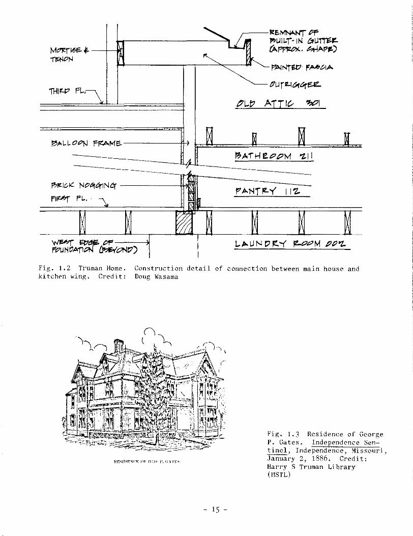
dd . . 11 a 1t1on. (See Fig. 1.1 and Building Chronology Drawings.)
Resembling the massing of a two-story American I-House, the 1867 struc-
ture is shown with a medium-hip roof. Recent investigation at the west
end of the old attic (301) revealed extant framing of a hip roof with
painted fascia board and remnants of a built-in sheet metal gutter.
Thus, the east wall of Truman dressing room (209) and hall (208) was
originally an exterior wall. The smaller kitchen wing (kitchen 113,
pantry 112, butler's pantry 111) is shown with a shallow-pitched, gable
roof. A September, 1986 physical investigation revealed that the
kitchen wing (113) was balloon framed at the floor joists, north wall.
In addition, there is evidence of an intermediate kitchen partition.
Presumably, the kitchen wing was constructed as a one-story or one-and-
one-half story addition with the roof altered to its existing height and
configuration in the remodeling of 1885. (See Fig. 1.2.)
As a prominent and successful Independence businessman who had made his
fortune from "Queen of the Pantry Flour," George P. Gates decided to
construct a sizable "addition" to his home at 219 North Delaware. (See
Fig. 1.3 and Appendix E (f), 1886 map.) Designed by builder and
architect James W. Adams for $8,000.00, the house was the most expensive
residence built in Independence in 1885. 12 (See Fig. 1.4.) Adams'
- 3 -
two-and-one-half story frame Victorian "addition" to the existing 1867
structure included at the first floor level: living room (104), bedroom
(105), vestibule (101), and portions of the central hall (103) and
dining room (110).
The second floor level included: master bedroom (204), Truman bedroom
(205), storage room (213), alcove (201), and portions of the central
hall (202) and bedroom (210).
The 1867 wing (which was damged by a fire that occurred after 1885)
remained a kitchen area (113) on the first floor. In all probability,
its second floor space (213) was converted into a sewing room/sitting
room during Bess Truman's childhood and early married life. It later
became a storage area sometime after Elizabeth Gates' death in 1924. 13
Porches included at the first floor elevation: 104B, 114A, B and C,
lOlA, and a porch which is now occupied by bathroom 106 and porch 107A.
(See Fig. 1.5.)
Recent findings that show physical evidence of the two different periods
of construction previously discussed (1867 and 1885) involve the inves
tigation of building materials and techniques, and conclusions drawn
from a paint analysis.
Based upon the most recent assumptions of the building's chronology,
- 4 -
several sections of exterior walls of the Truman home were removed and
studied. It was found that the east wall of the kitchen wing (113) is
constructed of brick nagging without sheathing and uses poplar siding.
Samplings from other wall portions, i.e. thin flat studs with sheathing
using pine siding, reveal a later period of construction. This sample
was taken from the 1885 section of the Truman home. (For further infor
mation, see Physical Investigation Report, Truman Home, July, 1984.)
Framing systems and stratigraphies of exterior paint layers also vary
with construction dates. While the 1867 portion of the home uses a
let-in system of framing, the 1885 portion does not. In addition, the
oldest extant siding appears to be on the 1867 structure. The strati
graphies found in samples from the 1867 portion show the greatest number
of paint layers -- approximately twenty-three. Paint samples extracted
from the 1885 section verify that date.
After marrying David Wallace on June 13, 1883, Margaret (Madge) Gates
(George Gates' oldest daughter), claimed 219 Delaware as their address
for an unknown period during the late 1880s. Then in 1904, one year
after David Wallace committed suicide, Madge and her four children
(Bess, Frank, George and Fred) permanently moved into the Gates'
mansion. 14
With this new arrangement, Madge could care for her aging parents.
George P. and Elizabeth moved to the first floor bedroom where the
- 5 -
southeast porch (106) was converted into a bathroom. (See Fig. 1.6.)
This occurred between 1907 and 1910. 15 In addition, a southeast section
of porch was added to kitchen porches 114A and 1148, and a sleeping
16 porch (206) was included at the second-story level.
For almost a century, the home at 219 North Delaware basically remained
the same. Only minor alterations were made to fit the needs of the
extended family that shared the home. After Bess Wallace and Harry
Truman were married in 1919, a year after the death of George Gates,
they, too, established their residence at 219 Delaware. 17
In 1924, after the birth of President and Mrs. Truman's daughter, Mary
Margaret, a passageway (206A) was built connecting the Truman's bedroom
(205) with the bedroom (210) of their new child. 18 A portion of the
second floor sleeping porch was used for the passageway. Also con
structed during the 1920s was a backyard pergola (HS-04). 19 (See Fig.
1. 7.)
For more than a decade---from the time that Harry Truman won the 1934
Democratic nomination for the United States Senate until 1945 when he
became the thirty-third President of the United States---the house at
219 North Delaware was neglected. Although minor in nature, there were
several household repairs accomplished, yet by the spring of 1945, the
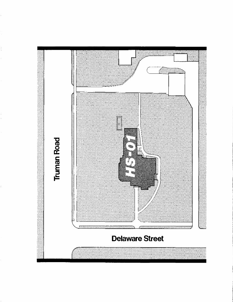
. d f . . 20 property was in nee o maJor renovation. (See Figs. 1.8 and 1.9.)
- 6 -

Concerned about the appearance of her family home, Bess Truman made
arrangements to begin exterior renovation of "The Summer White House" as
it was then called. (See Figs. 1.10 and 1.11.) Work at 219 North
Delaware included replacing rotted millwork and slate shingles, covering
the worn, grey exterior with white paint, and trim areas with Kentucky
green. 21 The second floor bath (211) was also remodeled with a new blue
porcelain tub, stool, and sink.
The only physical change to the Truman home during the presidential
years was the rear porch construction ( 114A and B). In April 1950, this
porch was refloored and extended to the east by six additional feet,
supported by brick piers, and screened-in (114C). 22 Based on evidence
from paint trim samples, it appears that the last porch extension may
have been partially constructed with reused materials from the earlier
rear east porch. 23
In January, 1953, one month after the death of Madge Gates Wallace,
Harry and Bess Truman left Washington D.C. as private citizens. The
former first family then returned to 219 North Delaware and purchased
the home in July. 24 That same year, the Trumans began to make repairs
and conduct interior changes to their home. This "modernization"
included: wallpapering first and second floor rooms; construction of
attic storage space; construction of cabinets in the east wall of
Mrs. Truman's dressing room; wall-to-wall carpeting throughout the first
floor (except the kitchen); and extensive interior painting. 25 In
- 7 -
addition, shelves were constructed in the library (109) sometime during
the 1950s.
In 1954, the old cement floor in the basement's utility area was exca-
vated. Originally, this area was elevated four inches from the re-
mainder of the basement. To permit an increase in headroom and to
repair plumbing, an additional four inches was excavated for the base of
26 the new concrete floor.
During the 1970s and 1980s, a few minor alterations were made to the
Truman home. The original slate roof was replaced with grey fiberglass
asphalt shingles in July, 1969. 27 The rotted front steps (non-original)
were replaced, and the rotted balusters on the north side were also
28 replaced, c. 1974. In addition, the damaged pergola which had been
reconstructed in 1944, was removed, c. 1970. 29 In December, 1981, the
main chimney was tuckpointed.30
On February 23, 1972, 219 North Delaware was designated a National
Historic Landmark by the United States Department of the Interior and
listed in the National Register of Historic Places. Following the death
of Mr. Truman, the City of Independence, with the full support of his
widow, established the Harry S. Truman Heritage District. (More
commonly known as the Harry S. Truman Historic District.)31
Following the death of Mrs. Bess Truman on October 18, 1982, the
- 8 -

dictates of her will left the property to "The United States of America
to be held and operated by it under the direction of the Archivist of
the United States, in conjunction with the Harry S. Truman Library. 11 32
Secretary of the Interior James G. Watt signed Designation Order No.
3088 declaring 219 North Delaware the Harry S Truman National Historic
Site. Under the auspices of the National Park Service, the property
became the Twenty-seventh Presidential Site in the National Park System,
on December 12, 1982.33
- 9 -

Notes to Chapter One
1. Ron Cockrell, Historic Structures Report: History and Significance. Harry S Truman National Historic Site, Independence, Missouri (Omaha: National Park Service, Midwest Regional Office, 1984), 11. Hereafter cited as "HSR."
2. Ibid., 10.
3. Ibid., 11.
4. Ibid.
s. Ibid., 12.
6. Ibid. It has been suggested that because of the increase in value of lots 2 and 3 (coupled with the fact that with his indebtedness, Hay also lost his home), a structure could have been present on the site as early as 1848. Although the theory speculates that the east wing (the kitchen wing) of the Truman home was built prior to 1850 (and later incorporated into the Gates' mansion), recent findings suggest otherwise. The following items have been observed and strongly indicate that the east wing was built concurrently or as an addition to the 1867 structure: 1) the sill beam of the 1867 main house is located to the east edge of the east foundation 2) the wall between the kitchen and dining room has brick nagging 3) the floor in the kitchen wing expands beyond the first joist. In addition, it was found that the earliest paint sample taken from the east wall of the kitchen wing dates 1867.
7. Ibid., 14.
8. Ron Cockrell, Historic Resource Study: The Trumans of Independence, Harry S Truman National Historic Site, Independence, Missouri (Omaha: National Park Service, Midwest Regional Office, 1985), 16. Hereafter cited as "HRS."
9. HSR., 16-17.
10. Ibid., 18.
11. HRS., 24. George P. and Elizabeth E. Gates probably came to Independence from Illinois in the spring of 1867, or according to a local historian, perhaps George P. Gates came alone to the area to investigate the property. His family (in 1866 in Illinois, Elizabeth had a baby, Myra) could have joined him at a later date. In addition, it is also known that Gates' father and mother were living in Independence in 1866, so it is possible that George P. Gates resided with his parents until their home was built.
It is also important to note that A. Ruger, the artist of Bird's Eye View of Independence came to the area in 1867. The date of publication was not more than one year after the artwork was finished. From this information, one can conclude that when Ruger came to Independence, the
- 11 -

1867 Gates' home was underway or already completed. For information on Ruger see: John\\'. Reps, Views and Viewmakers in Urbal' America 1825-195. Columbia: University of Missouri Press, 1984.
12. HSR., 30-31.
13. Ibid., 93.
14. Ibid., 47-48.
15. Ibid., 48.
16. Ibid., 152.
17. Ibid., 74.
18. Ibid., 76.
19. Ibid., 88.
20. Ibid., 115.
21. Ibid., 116.
22. Ibid., 132, 152.
23. Marie Carden, "Paint Analysis and Recommendations for the Harry S Truman Heme National Historic Site, Independer.ce, Missouri" (North Atlantic Historic Preservation Center, National Park Service, Bostor., MA, May, 1986, photocopied), 12. It is important to note that at the time cf this writing, the information in this reference concerning the kitcher wing and porch is in error.
24. HSR., 178.
25. Ibid., 185-88.
26. Ibid., 198.
27. Ibid., 266.
28. Ibid., 287.
29. Ibid., 258.
30. Ibid., 288.
31. Ibid., 292.
32. Ibid., 295.
33. Ibid.
- 12 -

Fig. 1.1 Bird's Eye View of Independence. A. Ruger, 1868. Detail. Credit: Jackson County Historical Society
iHIW fl..,
~--!tE.~PF 1"JU!l-T· 1N ~urn;~ tA~, hHAP!E-)
t1U f If.I C-t&f'r:£..
~L..!7 ATiit- ~I
f?"-IC-K Nt:>6f4"1Ntf ------#lt'::lltt
fl~ FL..
Fig. 1.2 Truman Home. kitchen wing. Credit:
Construction detail of connection between main house and Doug Wasama
- 15 -
Fig. 1.3 Residence of George P. Gates. Independence Sentinel, Independence, Missouri, January 2, 1886. Credit: Harry S Truman Library (HSTL)

Fig. 1.4 Truman Home, c. 1900. West elevation (looking east). One of a series of the earliest extant photographs of the structure. Note the absence of the roof line decorative grillwork as shown in the 1886 Independence Sentinel. Credit: HSTL
Fig. 1.5 Truman Home, c. 1905. Porch, northwest elevation (looking southeast). Bess Wallace Truman sitting on the original porch balustrade. Credit: HSTL
- 17 -
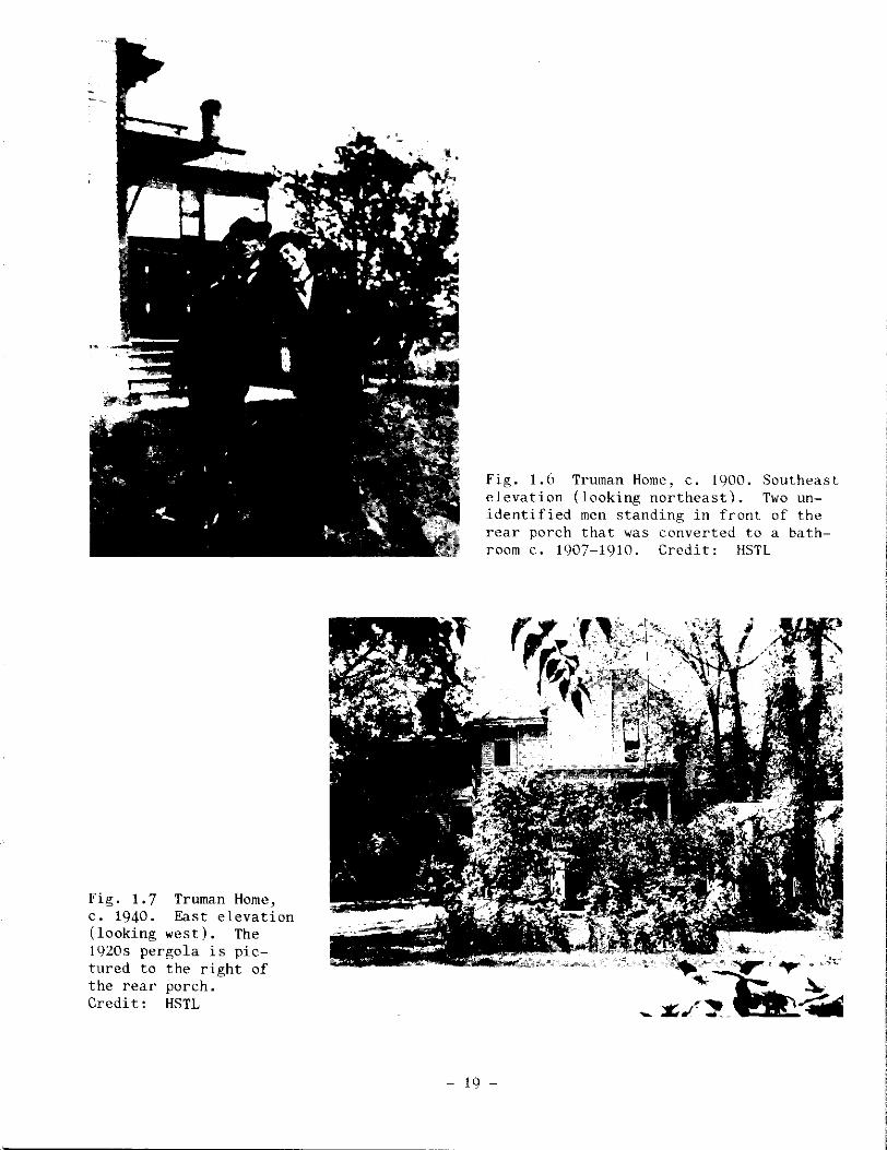
Fig. 1.7 Truman Home, c. 1940. East elevation (looking west). The 1920s pergola is pictured to the right of the rear porch. Credit: HSTL
Fig. 1.6 Truman Home, c. 1900. Southeast elevation (looking northeast). Two unidentified men standing in front of the rear porch that was converted to a bathroom c. 1907-1910. Credit: HSTL
- 19 -
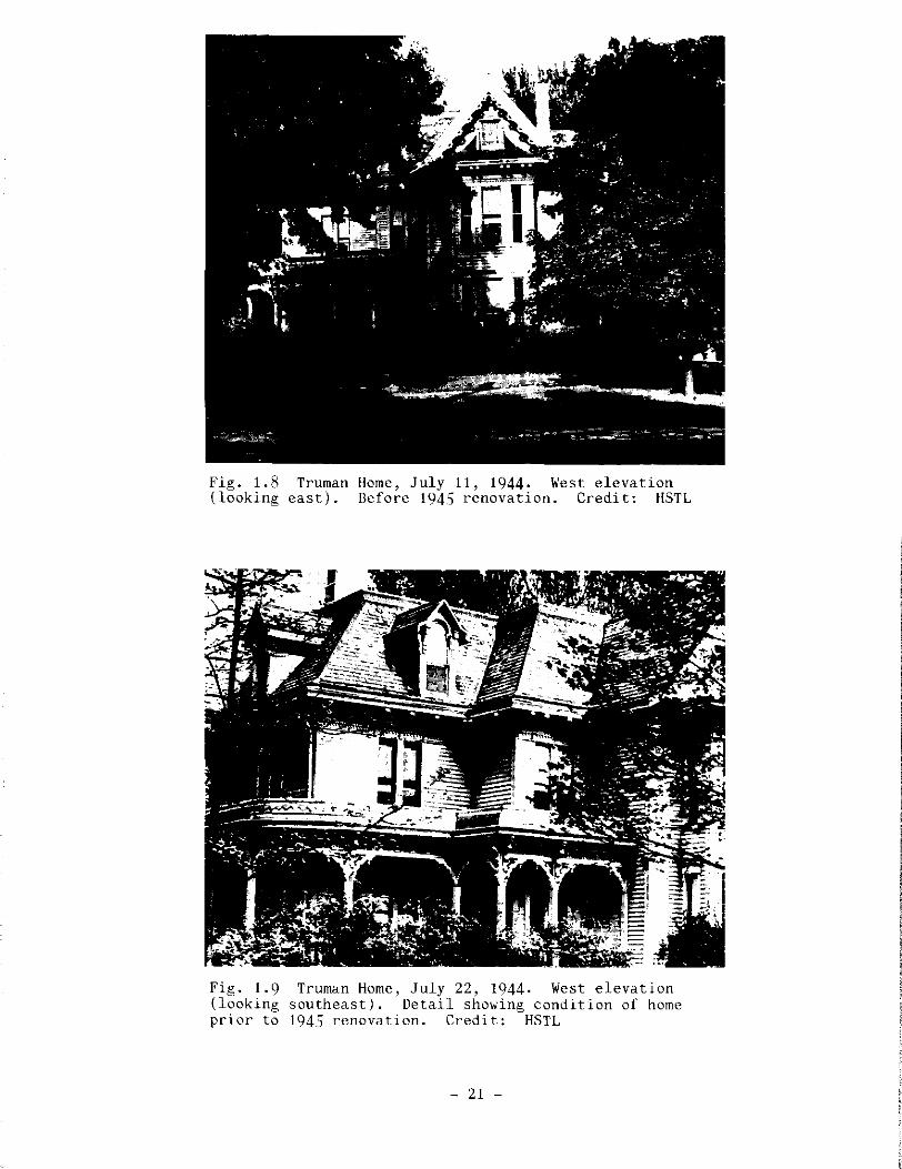
Fig. 1.8 Truman Home, July 11, 1944. West elevation (looking east). Before 1945 renovation. Credit: HSTL
Fig. 1.9 (looking prior to
Truman Home, July 22, 1944. West elevation southeast). Detail showing condition of home 1945 renovation. Credit: HSTL
- 21 -

Fig. 1.10 Truman Home, May 21, 1945. West elevation (looking southeast). Workers begin renovation. Credit: HSTL
Fig. 1.11 Truman Home, June 27, 1945. (looking east). After 1945 renovation.
- 23 -
West elevation Credit: HSTL
Delaware Street

II. Existing Conditions - Truman Home (HS-01)
Introduction
The Truman residence was constructed over a period of years with
numerous additions and revisions to the initial structure. This staged
construction is reflected in the various configurations of the struc-
tural system throughout the building. The residence is of wood frame
construction supported by a stone foundation with framing materials and
systems varying in size and detailing depending on the period of con-
struction. Variations in ceiling height due to the popular style at the
time of an addition created unusual detailing within the structure in
order to achieve a uniform exterior appearance. This is particularly
evident within the attic space, where roof and wall framing reflect such
d ·1· 1 etai ing.
Architecture and Engineering Team
Architectural investigation and analysis was performed by the staff of
Restoration Associates under the direction of E. Eugene Young, AIA.
Structural investigation and analysis were performed by the staff of
Harper and Kerr Consulting Structural Engineers, P.A., under the
direction of Gary Harper. Plumbing and heating, ventilating and cooling
system investigation and analys;s were performed by the staff of
Associated Engineering Consultants under the direction of Tony
Hitchcock.
- 27 -

The Architect/Engineer team conducted a detailed field investigation of
the Truman home in connection with the field measurement process. The
areas investigated included the structural systems, and the heating,
ventilating and cooling systems. Specifically excluded from the
investigation were site utilities, and the electrical and communication
systems.
Recording and analysis of the condition of architectural features are
not a part of this report but are noted on the Existing Condition
Drawings. This report analyzes the results of the field investigations,
describes the current capacities of each system, and identifies serious
deficiencies. Recommendations for structural reinforcement of the
porches were made at the site by Gary Harper (Harper and Kerr), Gene
Young (Restoration Associates) and members of the National Park
Service, 2 so that the work could be done prior to opening the house to
the general public on May 12, 1984. 3
Scope of National Park Service Work
During the investigation and analysis of the house, the National Park
Service performed various segments of repair work (from 1984-1986)
either with their staff or independent contractors. The contract
documents for this work were prepared by National Park Service staff.
The following is an outline of the scope of National Park Service work:
A. Replacement of the entire electrical system by an electrical
contractor. Most of the historic electrical system was left
- 28 -
in place and disconnected, for preservation purposes. Record
ing of the existing and new electrical system was done by the
National Park Service.
B. Replacement of the metal roofing, flashing, gutters and
downspouts by a sheet metal contractor.
C. Reinforcement of the wood porches and first floor structural
members from the basement was accomplished by National Park
Service staff utilizing recommendations of the
Architect/Engineer team.
D. Repair of deteriorated exterior wood trim and decorations was
completed by a single contractor in November, 1985.
E. Field investigation was completed in 1984 by National Park
Service staff in preparation for paint stripping and
repainting.4
Building Description and Analysis
The asymmetrical, two-and-one-half story, white clapboard structure is a
Victorian, Queen Anne landmark. It can be further classified as a
spindlework Queen Anne with hipped roof and lower cross gables.
The principal portion of the Truman home is topped by a metal-decked,
dentiled "widow's walk" and four gabled dormers fitted with jalousie
windows. The trim of the projecting eaves of the main roof features a
molded fascia and decorative frieze work adorned with heavily ornamented
wooden brackets set directly above the second floor window jamb trim and
- 29 -
corner trim. One-over-one, double-hung windows are predominant.
The prominent west facade is marked by a two-story bay window featuring
multipaned colored glass set in wood muntined double hung windows. The
bay window is capped by a bell cast sheet metal clad roof with projec
ting eaves. A multipaned colored glass casement window with a pedi
mented hood is set within wing walls formed from the bay window roof. A
gabled roof with decorative verge boards extends over and above the bay
roof. A similarly detailed gabled roof also exists at the south
elevation.
From the west bay window a veranda stretches north, then curves east and
continues to a two-story north bay window which is characterized by a
saw-toothed, horseshoe-shaped ornament set within the plain fascia of
the bay window's gable roof. This highly ornamented veranda features a
mansard parapet, jigsaw frieze boards, four types of brackets and
perpendicular lattice skirts. A second, two-bay porch of the same
characteristics, but without a parapet, protects the south entry into
the living room. (See Figs. 2.1-2.4.)
The main or west entry into the house is situated just north of the west
bay window of the 188.5 addition. The double-leaf, nine-foot tall doors
feature Eastlake style detailing with etched glass panes. The entry
leads to a small ceramic tile floored vestibule bay and finally to
another set of Eastlakian enriched doors. These doors open to a central
- 30 -

hall (103) which is adorned with Lincrusta-Walton wainscoting. The
primary double-landed, U-shaped stairway at the south wall of the
central hall features Lincrusta-Walton along its rake, a highly
ornamented wooden baluster, and a newel post capped by a feminine
luminiare.
Landscape (For site conditions, see Fig. 2.5.)
Topography
The site of the Truman home slopes gently eastward toward the rear of
the structure, from a relatively flat ground at the property's western
half. The site slopes approximately 5 percent, falling nine feet from
west to east.
Vegetation
The Truman home property contains several species of trees including
nine maple (west, north, south of structure); two oak (south of
structure); and three Siberian elm (south of structure).
The maple located at the southwest corner of the property, branching
over into the alley, is devoid of foliage and branches on the east side
except at the crown. Leaves on the west side exhibit small holes and
ragged edges. Leaves are wilted, i.e. edges of leaves curl down. The
maple directly south of the concrete walk to the main entrance of the
Truman home has only one lower branch with foliage remaining (west side
- 31 -
of trunk), in addition to a stub of a limb that has snapped off three to
four feet from the trunk. Foliage exhibits good color and appears
healthy.
The maple directly north of the walk has a lower branch on the east side
which has lost foliage and bark from outer three to five feet .. Other
wise, the tree has full shape and foliage exhibits gocd color and
appears healthy. Located south of the historical marker (HS-11),
another maple is not as tall or as fully shaped as the other maples
lining the west property line.
In addition, there is an a8sortment of informally planted shrubs and
bushes located along the south property line near the alley, along the
main elevation of the Truman home and to the north of the rear porch.
Peony beds, irises, roses and ornamental grasses appear throughout the
lawn with a high concentration of plantings at the eastern edge.
Walkways and Driveways
There are two concrete walks on the Truman property: one leading from
the Delaware Street sidewalk to the main entrance and one that leads
from the rear drive winding around the south elevation of the structure,
finally connecting back to the west walkway. Although the location of
the walks is historic, the sidewalk material is not, except for a rear
sidewalk extending from kitchen porch steps to the driveway.
- 32 -

An alley on the south end of the property line has been repaved a rrumber
of times because of the substandard base of the roadbed. In addition,
there is a second asphalt drive on the east end of the property off of
Truman Road. Both drives lead to the Carriage house and join at its
eastern elevation.
Fences
A five foot high, steel fence (HS-03), including a driveway gate at the
northeast corner, fully encloses three sides and partially encloses the
east edge of the Truman property. This black painted fence constructed
of stock steel tube and bar and set in concrete footings, was erected in
November 1949 at the insistence of the Secret Service to protect the
Truman property from potential intruders and souvenir hunters.5 In
addition, there is a portion of a chain link gate fence located at the
southwest corner of the Carriage house, probably a portion of a gate
which spanned the drive between the Carriage house and Wallace garage.
Four pedestrian gates exist at the Carriage house, the west entry, and
two at thEo Wallace home which is to the east of the Truman home, The
double-leafed driveway gate and pedestrian gate are inset from the
sidewalk with curved fence sections. Both the driveway and west main
entry gate locks can be operated electronically from inside the home.
Miscellaneous Structures and Archeological Remains
A thirty-four foot flagpole (HS-08) was installed June 26, 1945 near the
- 33 -
northwest corner of the site. 6 In addition, there are four concrete
slabs: two (used for a/c units) at the north end of the Truman home,
installed by the National Park Service in 1985, another at the northeast
driveway gate and a fourth located to the northeast of the Carriage
house. A gas lamp (HS-09); sundial (HS-07); a birdbath (HS-05); and a
historical marker (HS-11) are also located on the property.
The remains of historic structures include: the stone and brick
foundation of the pergola (HS-04) located at the northeast portion of
the property; the site of the Secret Service security booth (HS-06)
located west of the Carriage house. A concrete capped cistern (HS-10),
installed in 1885 (located under porch 113A), was sealed in 1926. A
triangular concrete foundation (HS-12) in the east yard is suspected to
have been a flagpole base.
Environmental Considerations
The following, obtained from the National Weather Center in Kansas City,
Missouri, are averages for the Kansas City Metropolitan area taken over
a 30-year period ( 1955-1985).
Heating Days (based on 65°)
Cooling Days (based on 65°)
5,283
1, 333
Average Yearly Rainfall= 35.16 inches
Average Snowfall = 20.4 inches
Humidity = high morning 80%
daytime 60%
- 34 -

Wind
late afternoon 60%
10.7 mph
Underground Utilities
On-site underground utilities include a buried electrical line for the
west gate latch (south of walkway to rain entrance); a buried South
western Bell telephone line running southeast from the south elevation
of the Truman home installed 1985; buried power and security lines
(east-southeast from the Truman home to the Carriage house, 1985); and a
buried Independence Power and Light line running due north from the
kitchen wing (113) 1985.
A 2 inch steel gas main is located on the south side of Truman Road,
running west from Delaware Street to the Secret Service booth site.
There are buried telephone cables, conduit and fiberoptic cables within
the Truman Road right of way. In addition, there are two 8 inch sani
tary sewers: one runs north within North Delaware Street to Truman Road
and another runs east and west within the alley. Storm sewer lines are
within the Truman Road right of way.
Foundation
The residence is supported by a random-course limestone foundation, the
limestone being similar in color and texture to that common to the area.
The foundation wall averages approximately eighteen inches in thickness,
and the stone and mortar of the foundation wall are basically sound.
- 35 -

However, the interior face of the foundation is powdery to the touch,
indicating deterioration due to rr:oisture penetration from the exterior
or rising dompness. The foundation walls show a minimum of differential
movement and are relatively crack free. Within th<· original stone work
the only major cracks noted were in the south basement roc·m ( 005), under
the living room (104) on both sides of the brick fireplace. One crack
west of the fireplace runs diagonally from the upper part of the wall,
extending downward approximately three feet following the mortar joints.
The crack averages approximately one-quarter inch in width. The widest
part of the crack is approximately one-half inch in width aPd is the
result of displaced mortar rather than wall movement.
The second crack in the south room is immediately below the window east
of the fireplace. This crack again is more the result of missing mortar
than wall moveme~t. The brick foundation under the main fireplace of
the living room (104) and master bedroom (204) is very soft, with the
surface crumbling to the touch. The mortar is powdery and the whole
assembly sho•s significant evidence of exfoliation. The brick does,
however, resist prcbing beyond the immediate surface.
Numerou' small cracks were noted in the plaster finish applied to the
stone wa11 within the remodeled utility area (002), below the kitchen.
These cracks were found on the south and east wall of the utility area,
generally running from the corners of the windows within this area. The
lower portion of the firebox on the east wall of the room has lost the
- 36 -

lower eighteen inches of plaster exposing the brick. This brick is
relatively soft to the touch and crumbles upon contact. 7
First Floor Framing and Condition
The kitchen (113) is thought to be within the original 1867 structure.
The basement area under the kitchen (002), having been remodeled as a
laundry room (002) in 1954 and also having been reconstructed at the
east end due to fire damage (occurring sometime between 1885-1900),
reveals a variety of structural detailing. During the remodeling of the
utility area, as noted previously, the perimeter walls were plastered.
This plaster continues up between the floor joists covering a layer of
brick laid on the original stone foundation between the joists. This
detail hides the connection betweer the floor joist and the perimeter
beam, so that the nature of this original connection can only be
speculated upon.
Based on the structural system found in the north basement room (003)
west of the laundry roo~ (002) and on information gained during recent
electrical modifications, it has been surmised that this area of the
basement is framed with a perimeter 5 x 8 oak beam directly on the etor'e
four.dation.
The oak floor joists of the kitchen (113) and pantry areas (111, 112) are
notched into pockets chiseled out of the south and north perimeter beaws.
- 37 -

At approximately the western limits of the stairway leading from the
kitchen to the basement, evidence of a fire can be noted by an original
floor joist that has been burned completely through at approximately
mid-span. This fire-damaged joist has been reinforced by the addition
of a newer joist installed adjacent to the east face of the charred
member. To the east of this reinforced joist, all floor joists appear
to have been replaced.
The floor of the kitchen and pantry areas is framed using 2 x 8 oak
floor joists, only a few of which are laterally braced by 1 x 3 diagonal
bridging at mid-span. The newer joists, previously mentioned, are
toenailed into a double 2 x 8 header at the stairwell. This header is
supported on the west end through a nailed connection by a single 2 x 8
joist spanning the room. Due to this connection and the bending stress
placed on the supporting floor joist, the kitchen floor is limited to an
estimated working load capacity of approximately 14 pounds per square
foot, considerably below the common building code requirements of 40
pounds per square foot for residential construction. A column at the
point of intersection of the header and floor joist now accepts the load
from the stairway header and increases the allowable live load of this
area of the kitchen to approximately 38 pounds per square foot, still
below most standard building code requirements. West of this stairwell,
the kitchen floor is capable of carrying a live load of approximately 52
pounds per square foot.
- 38 -
The floor of the dining area (110) has been strengthened with the
addition (c. 1940s-1950s) of a 6 inch steel 1-beam at approximately
mid-span of the floor joists. (See Existing Condition Drawings, No. 9,
First Floor Framing Plan.) This steel beam has helped the loading
capability within the southern section of the room; however, the
controlling factor for resisting loading is the reduced shear capacity
of the floor joists due to the notched bearing ends. They are set into
pockets cut into both sides of the central wood beam. (See Existing
Condition Drawings, No. 31, Framing Details, Detail 10.) Two square
wood posts at the western end and the recent installation {by the
National Park Service in 1984) of two steel pipe columns, 2-1/2 inch in
diameter, at the eastern end support the wood beam at intermediate
points. The resultant reduction in span compensates for the diminished
load capability of the double notched beam over its original longer
span. The dining room extends to the south (over basement room 007)
beyond the stone foundation wall which designates the southern limits of
the framing distinguished by the 5 x 8 wood beams. This portion of the
room is framed using a system similar in most of the southern section of
the basement which will be discussed later in this report. The critical
detail of this room, however, is not the typical detail but the con
nection of the floor joists supporting this portion of the dining room
to the perimeter 5 x 8 wood beam of the northern area. This connection
is made by notching the 2 x 8 floor joists to a three inch dimension and
setting this notched end into a pocket cut in a 2 x 6 member nailed to
the southern face of the perimeter 5 x 8 wood beam (See Existing
- 39 -

Condition Drawings, No. 31, Framing Details, Detail 5.) Several joists
have, over time and loading, begun to split at this connection. At some
point 1 x 6 tongue and groove boards of various lengths were attached
vertically to one or both sides of these joists supposedly to strengthen
the joists against the possibility of splitting. The reduced shear
capacity of this connection limits the floor in this area of the dining
room to a live loading of approximately 22 pounds per square foot, just
over half the commonly accepted residential code requirements. Modifi
cation of the connection detail would increase the loading capacity of
this area in excess of the capacity of the remainder of the dining room
(approximately 100 pounds per square foot depending upon exact mc·difi
cation).
The floor of the parlor/music room (108) has also been strengthened by
the addition of a 6 inch steel I-beam at approximately mid-span of the
original wood floor joists. The music room and the northern one-half of
the first floor central hall are connected by a wood beam having the
typical connection detail of the northern basement area (notched joists
sitting in pockets chiseled out of the original 5 x 8 wood beam). The
wood beam in this circumstance, however, has been strengthened by the
addition of a 2 x 8 member attached to the underside of the beam at one
span and by additional wood columns which have reduced the maximum clear
span to approximately four feet. Due to these modifications, the music
room is capable of carrying a maximum live load of approximately 107
pounds per square foot.
- 40 -
The central hall (103) of the residence, like the dining room east of
it, spans either side of the stone foundation wall separating the north
and south basement areas. Constructed at two different periods, the
framing system is not continuous, causing the junction of two systems of
framing details to be in effect. The south basement area has a peri
meter beam construction detail different from the north. The south room
perimeter framing is distinguished by 6 x 6 wood beams sitting on a
2 x 8 member which in turn sits on a 1 x 10 bearing directly on the
stone foundation. The bottoms of the floor joists are notched three
times to clear, respectively, the foundation, the 2 x 8, and then
interlocks into a pocket cut into the perimeter 6 x 6 beam. At the
point of juncture with the south wall of the northern basement area
where the 5 x 8 wood beam is located, this same notched joist detail is
in evidence, but the connection to the beam is through a system of
2 x 4's and 2 x 6 1 s nailed to the southern face of the 5 x 8 beam. The
central hall floor, due to the limited shear value of this connection of
the joist supporting the southern portion of this room and the original
5 x 8 beam, has a maximum live load capability of approximately 28
pounds per square foot. That part of the central hall (103) situated
over the northern basement area (004) has loading capabilities similar
to the music room -- approximately 110 pounds per square foot.
The floor of the living room (104) is another area of the residence that
has been modified with the addition of a 6 inch steel I-beam at approxi
mately mid-span of the floor joists. The maximum allowable live load of
- 41 -
this room is approximately 113 pounds per square foot. An additional
structural item, the •ood beam supporting the eastern wall of the living
room, has failed, which has minimal effect on the loading of the living
room but which has major consequences to the second floor's load sup-
porting capabilities. This beam exhibits extensive damage due to
splitting at the northern notched connection. This beam carries, via
transferal from the above wall, the load from the second floor central
hall and thus is of significant structural importance. The wood floor
joist immediately east of this beam has also split, most likely due to
the transference of load through the floor decking upon failure of the
beam. The split floor joist was temporarily shored by a wood column
wedged between the floor joist and stones stacked on the basement floor.
It is understood that this temporary support was placed by members of
the National Park Service to prevent additional damage just prior to the
on-site measuremer.ts and observations made for this report. In 1984
adjustable steel posts replaced the wooden post.
The floor of the downstairs bedroom, the Gates' bedroom (105) just east
of the living room, is structurally composed of wooden joists pocketed
into the perimeter wooden sill beams and was determined to have a live
load capability of approximately 51 pounds per square foot. The bath
adjacent to this bedroom (106) is of a newer construction and due to the
relatively short clear span, was found to have a live load of over twice
that of the bedroow., a load calculated to be approximately 120 pounds
8 per square foot.
- 42 -

First Floor General Condition
An investigation of portions of the first floor walls indicates that the
studs are approximately 16 inches on center, 9 although no physical
verification of this was made. Walls and ceilings of the first floor
area are generally in good shape showing little distress or movement.
The kitchen area (113) showed slight evidence of cracks over doors and
windows in the south and west walls. At these points the wallpaper has
separated, indicating a hairline crack. In numerous areas plaster seems
to have spalled under the wallpaper or the paper was originally applied
over loose areas. Some minor hairline cracking was noted at the
ceiling.
The dining room (110) had very few visible cracks, the most obvious of
which was one on the south wall just east of the bay window extension.
This crack runs vertically parallel to the face of the jog forming the
bay and approximately 1/2 inch from the impression of a panel of sheet
rock, applied prior to the installation of the last wallpaper project,
c. 1954, that has now pulled away from the wall. The north wall of the
dining room has a slight bulge, approximately the height of the doorway
opening into the library and approximately 2 feet east of that doorway.
The ceiling of this room shows some distress under the paper but no
evidence appears on the surface.
No major distress was noted within the library (109). The walls of this
- 43 -
room are virtually covered by bookshelves, thus making it difficult to
assess structural conditions behind the shelves. There is a discolor
ation in the paper on the ceiling with a small hairline crack running
the length of the discoloration. The limits of the stained area were
approximately 12 x 36 inches with the crack running lengthwise.
The parlor/music room (108) showed evidence of water damage in the
extreme upper northwest corner, extending approximately 12 inches each
way from the wall intersection. Several wallpaper seams had opened up
along the western wall, probably due to moisture or temperature
differential. There is a ceiling crack near the south corner of the
room. There is no sign of cracking under the major openings.
The living room (104) showed minor cracking on the north wall, being
most obvious at the eastern trim of the north win(ow of the front bay
assembly, then wrapping northerly around the corner. Three other cracks
in the same area extend from the baseboard diagonally upwards across the
wall at approximately 16 inch centers. The east wall of the living room
has two small horizontal hairline cracks, centered approximately between
the doorway into the central hall and the doorway to the Gates' bedroom.
The southern wall of the living room has a small crack that runs from
the upper western corner of the trim surrounding the doorway to the
south porch and arches across the wall to a point at the eastern face of
the fireplace, approximately level with the point of origin. The crack
then continues down the inside corner of the intersection of the fire-
- 44 -
place and the outer wall to the baseboard. A similar crack is found on
the western face of this fireplace, running up the inside face of the
intersection of the fireplace and the outside wall, crossing the south
wall at approximately the upper one-third point of the existing window
trim. Another small crack begins at the upper corner of this window
trim and runs to the ceiling. The plaster and paper in this area have
spalled indicating probable moisture penetration. A hairline crack was
noted on the west face of the wall just south of the bay window, running
up from the lower inside wall corner to a point approximately two-thirds
of the way up on adjacent window frame. This crack then continues
around the corner to said window frame. The ceiling of this room has a
small crack located in front of the fireplace running apFroximately
parallel to it. Some additional signs of stress show under the ceiling
paper.
The Gatee' bedroom (105) and bath (106) are in good condition with
virtually no evidence of cracks. The bath, however, does ha.ve con
siderable moisture damage in the southeast corner ard on the east wall
due to water previously leaking through the ceiling from the floor of
the sleeping porch (206) above. Storm windows were installed in 1985
behind the sleeping porch screens (206) to prevent water from infil
trating the porch deck anc'. bathroom ceiling.
The foyer (102) appears to be in good condition. This condition is
somewhat surprising considering the partial failure of the beam and
- 45 -
joist below this area. Some movement is evident in the wallpaper along
the east wall and evidence is found in the ceiling plaster of what
appears to ce old cracks that have been painted over. The vestibule
(101) just west of the central hall has ccnsiderable damage in the wall
and ceiling plaster, probably due to the wide variatiom, in temperature
in this essential1y unheated area. lO
Porches
Four wooden porches are -found at the five first floor doorways to the
residence. (See Existing Condition Drawings, No. 5, First Floor Plan.)
The kitchen, or rear porch, designated 114A, B, and C, was constructed
in phases. Porch ( 114-A) has a concrete capped stone cistern (HS-10)
under it and adjacent to the stairway. The wood joists of the porch
have been historically shored by 2 x 4 and 4 x 4 supports wedged between
these joists and the cistern, or in some cases between the joists and
the soil under the pore!:. These m2,ke-shift supports were not considered
as a permanent part of the framing system for the analysis of the load
carrying capability of these porches.
The southern portion of this porch (114A), being that pcrtion having
additior.al supForts as described above and lying along the south wall of
the kitchen, has surface deterioration due to salt and moisture decay.
The eastern portion of the same porch, lying east of the east wall of
the kitchen, appears to l:ave ceen constructed in at least two phases.
- 46 -
The initial phase, 114R, is approximately 6 feet in width and was
constructec using 2 x 8 timber members having an actual dimenEion of
1-7/8 inches by 7-3/4 inches. The eastern addition to this area of the
porch (114C) has 2 x 8 members with an actual dimension of 1-1/2 inches
by 7-1/4 inches. That portion of the porch east of the East kitchen
wall is supported on brick piers approximately 12 inches square. The
kitchen porch is constructed in such a manner that virtually all connec
tions are toenailed. The weaker section of the kitchen porch (114A),
that portion lying south of the kitchen, is weaker due to the inability
of these toenail connectionE to adequately tran,fer the shear loading of
the joists and an intermediate member to the foundation. This section
of the porch Ehould not be subjected to a live load of over approxi
mately 5 pounds per square foot. Modifications at the connection r,oints
of the joists an~ intermediate structural members that would allow each
structural member to carry a load equal to the full bending capability
of the member, would increase th<' allowable live load capa1'ility of this
porch to apFroximately 34 pounds per square foot. Additional streng
thening can be accomplished by modifying the temporary supports now in
place at joist mid--span to permanent stn·.ctural members. The other
sections of the porch have slightly different loading capacities.
Porch area 1148 is calculated at a live load limit of approximately 36
pounds per square foot and area 114C at approximately 42 pounds per
square foot.
- 47 -
The small porch (107A) servicing the eastern doorway to the first floor
central hall (107A) has a double floor comprised of 2-1/4 inch tongue
and groove decking laid on a 7/8 x S inch tongue and groove subfloor.
This doul:le floor is supported by four small built-up joists composed of
2 x 6 members with 1 x 4 ledgers vertically attached to eith<r side.
Fastened to the upper side of the ledgers is 15/16 x 3 inch tongue and
groo\e decking which is 1-7/8 inch below the under side of the subfloor
above. (See Drawings: Repainting and Repair of Truman Home 1/16,
United States Derartment of Interior, National Park Service, Midwest
Region, Omaha, Nebraska.) Although the span reached by these members is
only 4 feet, the live load capacity was determined to be only 30 pounds
per square foot. Due to the vertical members attached to either side of
what was assumed to be the original structural member, the exact method
of conrection at the northern end of the rr.ember was not determined. If
this porch is to be used extensively, modification of this connection
may be justified or at a minimum, slight destructive investigation may
be undertaken to determine the exact means of connection.
The south porch (1048) servicing the southern doorway from the living
room, is similar in ccnstruction to the rear porch. As with the kitchen
porch, the weakest point of the construction is the connections,
particularly at the intermEdiate span. Due to these connections, this
porch is capable of carrying approximately 15 pounds per square foot
live load. The existing joists and intermediate members are capable of
supporting approximately an 80 pound per square foot live load with
- 48 -
proper modifications to the end connections. The stairway of this
porch, which was in a severely deteriorated state due to moisture and
possible insect attack, has been replaced.
The front porch (101A) is similar in construction detailing to the south
and kitchen porches. Again due to connection details, the allowable
live load is limited to approximately 21 pounds per square foot. Joists
and intermediate members are capable of supporting approximately 100
pounds per square foot live load with proper modification of the
. d d ·1 11 connections an corner eta1 s.
Second Floor Sleeping Porch
Storm windows were added to the interior face of the sleeping porch
screens by the National Park Service, to prevent rain water from
infiltrating the porch deck. The deck was simply constructed over 2 x 4
sleepers which had been nailed through a sheet metal deck. Water infil-
tration caused the sheet metal to rust and decay badly, and some of the
sleepers to rot. Water then penetrated to the bathroom below causing
the wallpaper to severely stain. Rather than remove and replace the
entire sleeping porch deck and waterproof, storm windows were installed
to avoid the extensive damage to historic fabric in repairing the deck.
Only a small portion of decking material was replaced. (See Drawing
Detail 1 and 2, Sheet 6, from Repainting and Repair of Truman Home
(HS-01) Drawings, Truman Home NHS, Independence, Missouri.)
- 49 -

Second Floor Framing and Condition
The floor framing and wall framing systems of the second floor are
virtually unknown. An assumption has been made that the general pattern
of the first floor is repeated and to some extent this has been verified
by an area opened up in bedroom 210 during recent electrical medifi
cations and in an area of bedroom 107 where floor decking is spaced in
such a way that several joists are visible. Floor joists, where exposed
or otherwise measured, were found to be 2 x 8 members. Floor decking,
where exposed in closets and uncarpeted rooms, generally follows a
pattern that correlates to a framing system to that on the first floor.
The different time periods of construction and the deviations in room
ceiling height become evident at the second floor level. The various
rooms on this level vary in floor elevation and are connected by steps.
The ceiling of the second floor central hall (202) is distinguished by a
level change of approximately 2 feet.
The walls of the second floor seem to be in relatively good shape,
particularly surprising considering the partial failure of the beam and
joist previously discussed in the south basement room (005).
Within the northwest bedroom (207) a crack was noted on the ceiling
running parallel to the west wall and approximately 1/16 of an inch in
width at the south end, tapering to a hairline fracture at the north
wall. The south wall of this same bedroom has several randomly spaced
- ~ -
diagonal cracks at the extreme upper west corner. The most prominent of
these consists of a series of three cracks with plaster damage under the
wallpaper. The wallpaper is distressed at the northeast corner of the
room; however, paper has not separated.
The west wall of the second floor central hall (202) has minor stressing
in the wallpaper although no visible cracks are in evidence. The
plaster ceiling of this area adjacent to the stair (202-B) to the attic
has separated from the supporting lath and begun to drop down. National
Park Service personnel have stabilized this condition by supporting the
plaster with screws and large washers fastened into the ceiling joists.
Minor cracking was also evident over the stairway from the first floor
level over the upper landing. At the western edge of the central hall
(202), a small crack crosses the ceiling from the entrance door of the
northwest bedroom (207) diagonally across to the entrance of the master
bedroom ( 204).
The areas of distress in the master bedroom (204) were the south wall to
the west of the fireplace in that area between the fireplace and the
adjacent window and within the ceiling area of the room. A major crack
in the ceiling extends approximately from the middle of the fireplace to
the middle of the closet door (204-B). Three feet to either side of
this crack and parallel to it are cracks of less severity. Also, this
area of the ceiling exhibits a noticeable sag. Again, distress was
noted in the paper covering walls and ceiling with indications of
- 51 -
plaster separation behind the paper probably caused by moisture pene
tration from the outside. A water stain was noted on the north wall of
this room, approximately 2 feet west of the closet door at the ceiling,
with a corresponding drip pattern found on the wallpaper below.
In bedroom 205 also known as the Trumans 1 bedroom, all the walls are in
good condition and noted to be relatively crack free. Some minor
cracking was noted on the ceiling running diagonally from the northwest
corner to a point south of the east edge of the entrance of the central
hall. Three hairline cracks begin from this diagonal crack and run
east, parallel to the north wall of the room, diminishing as they con
tinue east.
Bedroom 210 and the passageway (206A) are both in good condition. These
walls show no evidence of cracking. Hairline cracks were found in the
ceiling of the small bedroom positioned above the area where the floor
decking changes direction, approximately 6 feet from the north wall of
this room (south of the closet).
Bath 211 has no evidence of cracking but an area of the ceiling adjacent
to and south of the bathtub, an area approximately 18 x 36 inches, has
sagged about 2 inches.
The Truman dressing room (209) has cracks in the two corners of the
fireplace flue chase from the music room (108) below. There is also a
-~-
small bulge in the wallpaper adjacent to the west edge of the doorway
(208D-1) in the south wall. At this point there is no evidence of
recent cracking and appearances present the possibility of the damage
having been there at the time the current layer of wallpaper was
applied.
The west wall has a diagonal crack in the upper north corner. The east
wall has small hairline cracks adjacent to the entrance doorway
(209D-l), one running north from the left corner of the upper doorway
trim to the adjacent wall and diagonally south up to the ceiling,
another running from the right corner of the upper doorway trim.
Room 213 was used for storage and shows little evidence of any movement
or cracking; however, it should be noted that three of the walls were
hidden by stored artifacts at the time of this inspection. A split in
the floor decking, approximately 26 inches west of the top riser of the
stairs going down to the kitchen is possibly part of the repair work
resulting from the fire damage found in this section of the residence. 12
Attic Floor Framing and Condition
The main attic area is divided into two levels, 302 and 303, and has
approximately 2 feet of elevation differential. This can be explained
by the joint which connects the earlier constructed 1867 structure to
the 1885 "addition." The lower level floor (302) is distinguished by
floor decking laid on 2 x 4 sleepers lying east-west over what appears
- 53 -
to be 2 x 6 ceiling joists running in a north-south direction.
There is evidence of a wood truss within the vertical area between the
lower and upper attic levels, noted when decking from the upper level
was removed during recent electrical work. Diagonal cords could be seen
lying east of the stairway connecting the two levels. The square heads
of two lag bolts were noted when the treads of the connecting stairway
were removed. The purpose of these bolts is unknown at this time,
although it is assumed that they connect to the lower cord of the truss.
The upper level (303) is structurally composed of 2 x 6 floor joists
that are notched at the ends to bear on 2 x 2 plates fastened at the
base of double 2 x 6 support members. These supporting members align
over the QOrth-south wall of the rooms of the second floor. 13
Roof Framing and Conditions
Attic Roof
Due to the installation of an insulation board and 1 x 8 sheet batten,
the exact rafter framing is not known. (See Roof Framing plan.) In the
areas that have been exposed, the structural members were found to be
2 x 6 rafters spaced approximately 24 inches on center. These rafters
support 1 x 10 roof decking. Various rafters are reinforced at the
lower limits by additional 2 x 6 or 1 x 6 members attached to one or
both sides of the rafter. A perimeter dogleg rafter assembly is
constructed by notching a 1 or 2 x 6 rafter to it over a 1 x 6 plate
- 54 -

sitting on the floor joist (upper level 303) or shot joist (lower level
302), as the case may be. The dogleg rafters gain additional support by
the decorative diagonal bracing noted on the exterior elevations.
To compensate for the elevation differential between the attic levels,
the lower level (302) has a perimeter short wall constructed of 2 x 4
members. This 2 foot high wall supports a 2 x 6 member approximately 2
feet in length sitting vertically on the short wall and perpendicular to
it, similar to a short joist. The free, interior end of this short
joist is capped by a continuous 1 x 6 header. This joist-like member is
topped by a 1 x 6 lying flat over which the 2 x 6 roof rafters are
notched in "bird-mouth" fashion. The assembly as constructed would be
unable to resist more than a minimal horizontal thrust from the rafters.
At some point additional bracing in the form of 1 x 6, tongue and groove
members was attached between the rafters and the floor (ceiling) joists.
The bracing is spaced at approximately 4 foot centers and is evident
along all three exterior walls of the lower level. These diagonal
braces, in conjunction with the stiffness developed by the nailed
connections in the short wall, offer the limited resistance to outward
thrust caused by the weight of the roof and rafter assembly and any
additional loading placed by snow and wind forces. 14
Attic Dormers
The four window dormers of the attic space reflect two different methods
of construction. The north and west window assemblies are of a more
- 55-

decorative nature and have a dogleg roof similar to the main structure.
These two gables are constructed of tapered 2 x 6 rafters supported on
2 x 4 frame walls. The dogleg is formed by a 2 x 4 positioned horizon
tally and attached to adjacent rafters on either side of the gable. The
two east window gables are constructed of 2 x 4 rafters lying flat
supported on 2 x 4 frame walls. These eastern gables have no roof
overhang. 1 5
Kitchen Wing Roof
The attic space (301) over the kitchen and storage area is a more
typical gable system of rafters and ceiling joists. This system is
composed of 2 x 6 and 1 x 6 members. This area has had extensive fire
damage and new rafters have been attached adjacent to the damaged units.
This reinforcement is true of virtually every structural member in this
area except for the four rafters and joists farthest east which were
completely replaced. This roof area is distinguished by a hip roof area
beginning at the level of the fascia of the main roof. The moderately
sloped area of this roof is constructed using 1 x 6 rafters. Most of
this framing appears to be of the same vintage as the replacement joist
and rafters, leading to speculation that the original 1 x 6 members were
totally destroyed by the fire16 which, as previously mentioned, occurred
sometime between 1885 and 1920. 17
Roofing Materials
In 1969, "as a result of winter ice damage and a severe July hail storm,
- 56 -
the eighty-year-old original slate roof was beyond repair. 1118 As a
replacement, the Trumans chose a new type of shingle on the market.
They selected royal grey, GAF fiberglass and asbestos 300 pound Fire
guard (two-tab) shingles with a number 9 granual. Since these shingles
have been in place for sixteen years, they are nearing the end of their
serviceable life. However, production of this type of shingle was
discontinued by GAF in 1984. No other shingle manufacturer currently
makes two-tab shingles. GAF can produce these shingles on custom order,
but requires a minimum quantity of 1,000 squares. About 34 squares are
needed to reroof the Truman home.
In March and April of 1984 the flat seam metal roofing, gutters and
downspouts were replaced. The old metal roofing was corroded and had
been coated with bitumen.
Wall System Framing (See Appendix F.)
Eight sections of exterior walls were investigated in 1984 by the
National Park Service. In general, three different wall systems were
encountered: walls with brick nogging but without sheathing; walls with
studs laid flat forming a 2 inch cavity and sheathing; and walls with
both brick nogging and sheathing. From the data collected in the
investigation, it was determined that most of the exterior walls are
balloon framed.
The sheathing and siding applied over the kitchen wing walls appear to
- 57 -
have been added after 1900. In addition, paint samples taken from this
section of the structure, match those from 1885 construction, indicating
residing was done. This may correlate with an extensive kitchen wing
fire around the same period. The brick nagging dates the construction
of the wing as the earliest portion of the structure, but wire nails,
rosin sized building paper, and the very clean surface of the sheathing
indicates these as replacement materials after the fire.
A similar type of construction exists in the 1867 portion of the
structure but without sheathing. To existing knowledge, poplar siding
occurs only in this portion of the house. The remainder of the struc-
ture's siding is white pine. (See Fig. 2.6.)
The walls of the portion of the house encompassing the living room
(104), Gates' bedroom (105), foyer (107), and the southern portion of
the dining room (110), are constructed of 2 x 2 studs laminated from
1 x 2 material or 2 x 3-1/2 (laid flat) balloon framed studs forming a 2
inch cavity. Seven-eighths inch tongue and groove sheathing is fastened
horizontally with cut nails. No nagging was encountered here.
All sheathing encountered is tongue and groove white pine in good
condition. All stud material encountered is oak, in good condition.
The brick nagging (laid in shiner course) and mortar joints encountered
. d d" . 19 are in goo con it1on.
- 58 -
Exterior and Interior Stair Systems
The exterior stair systems are in good condition having recently been
repaired or replaced and repainted.
The main interior stair (108A) is in basically sound condition although
some minor problems exist. There is no evidence of the framing pulling
away from the wall or excessive deflection in the outside stringer.
When walked upon, creaking of the stair is minimal except at one or two
isolated treads. The treads and risers, which are painted or stained
black are covered with a grey carpet runner. The newell posts and
balusters are stained a very deep mahogany whereas the railing is
stained brown. The lower ends of some balusters are loose where they
are mortised into the treads. Nosing at the side of the treads displays
varying degree of looseness, partially caused by Margaret Truman
climbing on them as a child. 20 The finish is worn in limited areas.
The base of the lower newell post is split vertically on the west side.
The attic stair (202B) is in fair-to-poor condition, having been damaged
at the lower end by water leaking through the roof above which has
eroded the finish and exposed the bare wood. This stair is comprised of
oak treads and risers stained brown, pine stringers which are grained to
resemble oak, walnut turned spindles stained nearly black and a brown
stained railing. The turned spindles are quite loose where they fit
into the rail or treads and can easily be pulled from their sockets.
Carpet rod holders on the treads indicate that these steps were carpeted
- 59 -
sometime in the past.
Exterior Envelope
The siding on the Truman home is clapboard with 4-1/2 inch average
exposure and is painted white. On the 1867 portion of the structure the
clapboard is poplar except on the kitchen wing which is white pine. The
clapboard on the 1885 portion is white pine. The difference in siding
materials on the 1867 portion and the kitchen wing may be attributed to
a fire that occurred after 1885 (date unknown) and resulted in the
original siding being replaced. All siding, millwork, brackets, porch
ceilings, and fascia are now in good condition having recently been
restored. Work included stripping of most paint finishes to bare wood,
woodwork repair, and painting of all exterior surfaces. (See Drawings:
Repainting/Repair of Truman Home 4/11/85.)
Windows
All foundation and main structure windows are wood sash and prior to
restoration, were in very poor condition with loose glazing, broken
glass and rotted sash. Window repair included reputtying, reglazing and
replacement of deteriorated window components. 21 Except for broken or
missing sash cords at windows 108:W-2 (A and B), llJ:W-1, 201:W-1 (A),
204 A:W-2, 205:W-3 and 211:2-1, all windows are now in good condition.
Windows are painted green on the exterior and stained and varnished or
painted on the interior depending on location. The bottom rails of some
- 60 -
lower sash exhibit minor water staining, worn fin1sh, or crazing of
paint on the interior. The paint of the upper and lower sash (211:W-1)
in bathroom 214 is crazed throughout.
Originally each window on the first and second floors except in the
kitchen (113), bathroom (211), and storage room (213) had an upper and
lower pair of interior shutters as evidenced by the four recesses on the
side of each window frame. Each lower and upper leaf would normally be
supported by two hinges. Cut-outs for such hinges and their associated
screw holes are still visible. Certain cut-outs have been filled in but
·11 "d 22 are st1 ev1 ent.
Wood storm sash are in place on the following windows: 104:W-1,
104A:W-l(B), 105:W-l(A and B), 108:W-l(A and B), 108:W-2(A and B),
109A:W-l(A and B), 109A:W-2, 109A:W-3, and 112:W-1. Storm windows are
in good condition and painted white. Storm windows are hung from two
metal sash hangers and secured at the sides with metal turn buttons.
Parts of the storm window hardware are extant on some other windows.
Prefinished bronze color aluminum storm windows were installed in 1985
on the interior side of the east and south elevations of sleeping porch
(260) to direct rain water away from the sleeping porch floor.
Wooden framed screens are stored in the Carriage house. The frames are
painted green and are in fair condition.
- 61 -
The attic jalousie windows which replaced wooden sash in 1953, are
fitted with interior screens.
Doors
The wood exterior entrance doors and wood storm doors are in good
operating condition. Both types of doors are painted white. The north
jamb of the basement door 002:D-l was rebuilt in 1985. Constant use had
loosened the wall blocking built into the stone f oundaton. The screen
door 002:D2 was rescreened in 1985.
The interior doors are generally in fair-to-good repair except for three
doors that bind and have chipped, nicked, and worn finishes. The west
pocket door, 103:D-l(A), at the parlor is jammed and the east pocket
door binds as it is opened. This condition is caused by insufficient
clearance above the carpet and a slight sag of the lintel over the door
opening. Closet door D-2 in master bedroom (204) binds at the bottom
and will not close completely. The finish on interior doors is stain
and varnish, paint, or pine grained to resemble oak, depending on
location.
Exterior Finishes
The Truman home was repainted between October, 1984 and November, 1985,
because of the poor condition of exterior finishes. "Examination of the
exterior paint finishes in areas directly exposed to the elements re
vealed severe paint film failure, including cross-grain cracking,
-~-

alligatoring, and peeling. Even in places shielded by porches and
cornices, moderate paint film failure had occurred. A number of exposed
areas, including soffits, fasciae, and siding experienced near total
paint failure due to recurrent moisture penetration from deteriorated
roofs and built in gutters. • • more than twenty coats of paint
concealed deteriorated woodwork and cladding from direct examination.
On much of the projecting millwork, the final layers of paint had been
applied so heavily that stalactites in excess of 1/4 inch were apparent
due to paint dripping. 112 3 The scope of the work included thermal
removal (heat gun) of most paint from exterior painted wood surfaces to
achieve a sound surface for painting; repair or replacement of any
deteriorated portions of cornices, brackets, fascia, soffits, siding,
barge boards, posts, railings, balusters, porch flooring, ceilings and
steps, skirting, lattice, windows and doors; application of caulk; and
repainting the exterior including metal roofs. All exterior woodwork,
windows and doors received one coat of Pratt & Lambert Permalize alkyd
primer and two coats of Pratt & Lambert Permalize alkyd house paint in a
gloss finish. Siding, millwork, doors, and storm windows are white.
Window sash is green. A grey Pratt & Lambert Effecto enamel was applied
to exterior porch floors. White Effecto enamel was used on all exterior
metal surfaces including flat seam metal roofs, gutters, downspouts, and
built-in gutters. 24
A paint analysis performed in May, 1986 revealed that the siding was
painted a rust-red in 1867 and light green in 1885. The 1867 trim color
- 63 -

was warm grey which was changed to dark green in 1885. 25
Interior Finishes
The interior building fabric is generally in fair-to-good condition
except for certain ceilings - foyer (102)/central hall (103), dining
room (110), master bedroom (204), central hall (202), and bathroom (211)
- and portions of walls that show major distress, peeling wallpaper, and
water stains. The walls are papered throughout whereas the ceilings are
either papered or painted. Wallpaper patterns range from simple geo
metric designs to large floral prints with contrasting border. Areas
where peeling wallpaper is a major problem are the Gates' bathroom (106)
and the third floor vestibule (304). Only two of the painted ceilings,
foyer (102)/central hall (103) and Margaret's childhood bedroom (210)
have paint applied directly to the plaster. On the other painted
ceilings, paint has been applied over wallpaper, a fabric liner or a
1/8 inch thick fiberboard panel.
The majority of the cracks in the walls and ceilings are minor and
should not change to any great extent in the absence of water pene
tration or structural settlement. (See Existing Condition Drawings,
No. 5, First Floor Plan.) Fluctuations of temperature and humidity will
cause slight changes in these cracks. Minor cracks should be left 11 as
is, 11 but monitored carefully for any changes that could result in
further deterioration. Complete repair of all cracks would necessitate
removing and installing new wallpaper throughout the house. Although it
- 64 -
may be possible to replicate the existing patterns, the historic
character of the existing fabric would be lost. The sagging ceilings
are a result of the failure of the plaster keys between the wood laths
with water damage a contributing factor. Stabilization of these
ceilings will be required soon.
Carpeting in the dining room (110), and foyer (102)/central hall (103)
is in good condition having been installed in the spring of 1984. The
new carpet matches the historic carpet in color and weave except for a
dark grey sewn-in runner that guides the visitors through the house.
The historic carpet was carefully removed and is in storage. The
existing carpet throughout the remainder of the house is in relatively
good condition, free of severe worn spots or snags.
Encaustic tile in the front vestibule (101) and the three fireplace
hearths are in good condition. The light blue, stippled glaze ceramic
tile tub surround and wainscoting in bath 211 is sound as is the white
ceramic backsplash above the kitchen sink. In the Gates' bathroom (106)
the mastic on the yellow ceramic tile and dark green border has begun to
fail causing tiles to fall off the wall. The failure of the tiles to
adhere to the wall was affected by water leaking through the ceiling
from the sleeping porch above. Leaking of water has been repaired. Due
to the poor condition of the mastic, tiles will continue to fall off
sporadically.
- 65 -
The base, window, and door moldings are in good condition except for
certain window sills which display water stains, exposed bare wood and
crazed paint. In addition some of these have split longitudinally.
The lincrusta in foyer (102)/central hall (103), foyer (107) and stair
(108A) shows some diagonal and horizontal cracks and localized pulling
away from the substrate. The section on the north wall of foyer has
been coated with a gloss finish, possibly shellac or varnish and there
is evidence of a previous repair; underneath the stair, which was poorly
executed. There are three small areas which are missing.
The historic ceiling finish in the basement was 16~1/2 inch x 30-1/4
inch x 1/2 inch tongue and groove Cel-0-Tex panels fastened to the
underside of 1 x 4 nailers laid perpendicular and secured to the lower
edge of the floor joists. The Cel-0-Tex panels were removed in 1983 to
permit investigation of electrical wiring above. The 1 x 4 nailers are
extant; the panels were too damaged to salvage.
The new attic (302, 303) and window bay (302-A) has a finished ceiling
of 4 foot x 8 foot x S/16 inch sheets of Cel-0-Tex with butt joints and
white finish surface. The sheets are full size or trimmed as required
and are nailed directly to the underside of the sloped roof rafters or
to 1 x 4 nailers fastened to the underside of the sheathing boards at
the flat roof. Numerous panels are missing for a variety of reasons;
nails used had insufficient head diameter for adequate support, panels
- 66 -

were removed for installation of electrical and security wiring, and the
panels in the east dormer (window 302:W-4) of the lower level were lost
due to a localized fire in 1985. Debris in the stud space on the north
side of the dormer was ignited by a heat gun during the process of
exterior paint removal. In anticipation of replacing the asphalt
shingle roof (originally scheduled for the fall of 1986, but delayed due
to the difficulty of obtaining material to match the historic asphalt
shingles), National Park Service personnel have hung visqueen for
protection in areas where the Cel-0-Tex panels are missing.
Plumbing Services and Systems
The main water service to the house is provided by a 3/4 inch galvanized
steel pipe which enters through the north wall of the basement in the
laundry room (002). At this location, a main cut-off valve is in
stalled. From the cut-off valve, the cold water piping, replaced in
April, 1985, is then distributed to the domestic hot water heater,
bathrooms, kitchen sink, lavatories, washin~ machine and wall hydrants.
All the cold water piping is exposed on the basement ceiling with the
exception of the vertical piping to the second floor bath and bedroom
lavatory. 26
The house has a non-historic electric domestic hot water heater located
in laundry room (002). This water heater was installed in 1984 for the
use of National Park Service personnel at a non-historic basement sink.
The historic gas-fired heater, installed in 1974, was drained, but not
- 67 -
disconnected. From the historic hot water heater, the hot water piping
is distributed to the bathrooms, kitchen sink, washing machine and lava
tories. All the hot water piping is exposed on the basement ceiling
with the exception of the vertical piping to the second floor bath and
bedroom lavatory. 27
Waste and Vent System
All the plumbing fixtures in the home have cast iron, lead or galvanized
waste piping until the piping penetrates the basement floor where all
waste piping becomes cast iron under the concrete slab.
The Gates' bedroom (106) on the first floor has a 4 inch cast iron vent
stack up through roof R-6. Bathroom (211) on the second floor has a 2
inch cast iron vent up through the old attic (301) roof.
The lavatory in Truman bedroom (205) on the second floor, the kitchen
sink unit in kitchen (113) on the first floor, and the water closet
(007) are not vented to the atmosphere. 28
Gas System
Historic (c. 1885) System
There is evidence of a gas system in the walls and ceilings which
supplied gas to fixtures. Known terminations include the dining room
(110) chandelier and the music room (108) gas fixture.
- 68 -
Existing System
The main gas service to the house is provided by a 1-1/4 inch black
steel pipe which enters through the west wall of the basement in furnace
room (004). The main gas service then passes through a main gas cock
and pressure reducing valve before entering the gas meter which is
located on the west wall of furnace room (004). From the gas meter the
gas piping is then distributed to the furnaces, domestic hot water
heater, space heater, ranges, and yard lamp through underground copper
pipe. All the gas piping is black steel with the exception of one
section of pipe which is copper. This copper pipe has been noted on the
basement plumbing drawings. All the gas piping is exposed on the
b · 1· . h f . 29 asement cei ing wit ew exceptions.
Heating System
Historic
The original heating system relied on the use of three extant fireplaces
(located in rooms 104, 204 and 108), in addition to "an undetermined
number of stoves." The exact date in which the central heating plant
was installed in the Gates' mansion is not known but it is probable that
it occurred between the years 1885-1910. Fuel was first wood, then coal
and finally gas.JO
There is physical evidence of an old gravity-type furnace. (See
Existing Condition Drawings, No. 4, Foundation/Basement Plan, Room
005/006.) This area, where the furnace was located, is about 6 inches
- 69 -

lower than the surrounding floor. In this location there is a concrete
area with a definite edge that is approximately circular in shape,
corresponding to a furnace. In addition, there are bricks that follow
the shape of the concrete and remains of asbestos paper that have been
nailed to the underside of the joists and flooring directly above the
floor area previously described. There is also an underfloor duct that
starts at the edge of the recessed area and runs several feet to the
east, ending with an opening in the floor.
Two individual gravity-type furnaces (Model 1135, each at 135,000 BTU/HR
input LAN-A-15) with a common supply and return plenum were installed
sometime during the mid 1950s. In 1959, a modification was made to the
furnaces by installing a belt-driven fan inside the return air plenum
which converted the heating from a gravity-type to a forced air system.
The house is presently heated by a pair of Carrier, induced-draft gas
fired furnaces located in furnace room (004) replacing the historic gas
furnace in 1985. (The metal casing from the historic furnace was
salvaged.)
Ductwork
The furnaces supply air to the first and second floors through round and
rectangular ductwork to floor and wall supply grilles. On the first
floor there are transfer grilles installed in the ceiling of the dining
room (110) and kitchen (113), which transfers heat from these areas
- 70 -

through floor grilles in bedroom (210) and storage room (213) on the
second floor.
Return air is transferred from the first floor through floor grilles and
ductwork to the filters in the furnace. The second floor has no ducted
return air system. All ductwork and grilles are historic except those
modified near the furnace to accommodate the new system.
A single Honeywell wall thermostat located in central hall (103)
historically controlled the space heating temperature for the house. A
new thermostat was installed in the music room (108) in 1985.
A small gas space heater is located in kitchen (113). This unit was
used for supplementary heat for that area with some heat passing to the
storage room above through the ceiling transfer grille.31
Gas Yard Lamp and Interior Gas Fixtures
In 1964, Hadco Products, Inc., of Littletown, Pennsylvania, presented
the Trumans with a 6 foot "Gettysburg" style gas lamp made of cast
aluminum and solid brass accents standing on a concrete pedestal. The
gas lamp stands to the east of the main entrance of the Truman home.
Much of the gas tubing to the original overhead lighting system remains
extant behind the walls and ceilings. The chandelier in the parlor/
music room (108) remains connected to the historic gas system.32
- 71 -
Locations of capped pipe of the historic gas system which extend through
the ceiling include the laundry room (002), vestibule (101), butler's
pantry (111) and hall (208).
Ventilation System
The house is ventilated by means of a single speed belt-driven fan
located in the lower level (302) of the attic. This fan is controlled
by a Honeywell timer located at the bottom of attic stair (2028). When
the fan is in operation, the air that is exhausted from the house is re
lieved from the attic space through attic dormer jalousie windows. If
the fan is not in operation, the inlet to the fan is covered by a pair
of hinged doors at the top of stair (2028).33
In addition, a four-bladed ceiling fan (no manufacturer identification)
is located on the kitchen porch (114C).
Air-Conditioning System
Historic
Some limited air-conditioning in the house was provided by spot cooling
from two window air-conditioning units on the first floor. One air
conditioning unit is located in the west window of the Gates' bedroom
(105), and the other is in the north window of the kitchen (113). Both
window air-conditioners are factory package units with all controls
located on the front of the unit.34 These units were removed and placed
in storage in 1985. The library (109) windows 109A Wl:B also had an air
- 72 -
conditioner which was seasonally installed. It was removed before
National Park Service acquisition during the fall of 1982.
Non-Historic
In October, 1985, two outdoor condensing units (Carrier, series 38) were
installed on new concrete pads, north side of kitchen (113) in an effort
to control summer interior humidity and temperature levels.
Electrical Service and Systems
The house currently is serviced by an electrical system installed in
1983-84. The original electrical equipment and wiring have been
disconnected and left in place. All original lighting fixtures have
been left in place and are operational. The house originally used gas
lighting, one fixture of which is still in place in the parlor/music
room (108). The house was converted to electric service sometime
between 1886 and 1907.
The house is presently utilizing a 200 Ampere, single phase, 110/220
volt, residential service which is fed underground from a power pole
located along the south edge of Truman Road. The meter housings,
historic and non-historic, are located on the north side of the house.
The original aerial service conductors and service entrance equipment
have been disconnected and left in place adjacent to the new service.
- 73 -

The in-place service switchgear consists of one main 200 Ampere
distribution panel and four sub-panels located on the north wall of
laundry room (002). The four sub-panels supply respectively: basement;
first floor; second floor; garage, gates and porchlights. Historic
service panels are located immediately west of the new equipment and
consist of a main 110 Ampere breaker panel and one sub-panel.
The original wiring is comprised of open type knob and tube and some
non-metallic sheathed cable. All exposed original wiring in basement
and attic areas have been disconnected and left in place. In-place
wiring was run in electrical metallic tubing and flexible metallic
tubing which was fished between existing wall spaces during 1983-1984
electrical renovation.
The majority of receptacles and wall switches are original 2-wire type.
Some receptacles and wall switches were replaced with U.L. listed types
in 1984, An electric hot water tank was also added at this time. The
original attic ventilating fan is functional and controlled by a
Honeywell timer located at the base of attic stairway. Bathrooms (106)
and (211) both utilize wall mounted 110 volt electric space heaters.
Lighting fixtures throughout the house are functional, original units,
except on the west wall of the kitchen where new switches were installed
to operate yard lamps since the switch boxes on the south wall were in
accessible. These are now disconnected. Two switches, one at the west
- 74 -
gate and one at the foyer (102) painted red, are unidentifiable.
Lighting is predominately incandescent with fluorescent wall strips in
the bathrooms and a single ceiling fixture in the kitchen. Bedrooms
(105, 201, 205, 207, 210), living room (104), music room (108), and
entryway (103) utilize incandescent wall sconces with supplemental table
and floor lamps. Exterior lighting is incandescent with one pendant
fixture on the east porch ana west porch ceiling, in addition to a lamp
at the southeast corner of the kitchen porch.35
Lightning Protection System
A lightning protection sy&tem was installed in August, 1985 on the
Truman home (HS-01), the Carriage hc0use (HS-02), and the specimen oak
southeast of the Gates' bathroom (106). It consists of 3/8 inch
diameter by either 15 inch or 48 inch long copper point, nickel plated
terminal rods connected by copper cable, leaded, to 1/2 inch diameter by
10 foot long copperclad steel ground rods. The shorter terminal rods
are located at the ridge of each gable - main roof and dormers - of the
Truman home as well as the ridge of each gable and the center of the
cupola of the Carriage house. The longer terminal rods are used on the
chimneys of the home and four 30 inch terminal rods - one primary at the
apex and three secondary - are located in the upper branches of the
specimen oak. The home is grounded at four exterior locations; the
northeast corner of the library (109), the northwest corner of front
porch (101-A), the southwest corner of living room (104) and the
southeast corner of the Gates' bathroom (106). The terminal rods
- 75 -

located in the specimen oak also connect to this ground rod as well as
to a ground rod approximately 25 feet southeast of the trunk of the
tree. The ground rods for the Carriage house are located at its
northeast and southwest corners and are interconnected with the
weathervane. The grounding cable on the house is painted white and is
interconnected with the metal roof.
The historic telephone service (abandoned) connects to the house on the
south elevation. Two overhead cables are secured to porcelain insu
lators on metal angles, one above the other. Approximately 8 inches to
the east of each insulator is a second porcelain insulator identical to
the first, but without any wire connection. The two cables drop
parallel with the east side of the Gates' bedroom (105) window. One
cable enters the house through a hole in the water table. The other
enters a metal conduit which extends from the water table to grade and
is anchored at the water table with a metal strap. The abandoned
service terminates in the east end of the basement (006). The two
overhead cables connect to a pole in the south alley, southeasterly from
the point of entry into the house.
In addition, a butler bell system could be activated from the Gates'
bedroom (105) to ring bells in the Truman bedroom (205) and in the
- 77 -

kitchen (113). Bess Truman could summon a nurse by pressing a button on
the end of a 15 to 20 foot cord.
-78-
Notes to Chapter Two
1. Restoration Associates, a division of Solomon Claybaugh Young Architects, Inc., "Analysis of Condition Report HS-1 Truman Home, Truman Home National Historic Site" (Kansas City, February 14, 1985, bound copy), 2.1. Hereafter cited as "ACR."
2. Members of the National Park Service staff include: Skip Brooks, Facility Manager; Alan O'Bright, Historical Architect; Michael Lee and Lee Jamison, Exhibit Specialists (Restoration).
3. ACR., 1.1; 1.2.
4. Ibid., 1.3.
5. Ron Cockrell, Historic Structures Report: History and Significance. Harry S Truman National Historic Site, Independence, Missouri (Omaha: National Park Service, Midwest Regional Office, 1984), 146. Hereafter cited as "HSR."
6. Ibid., 128.
7. ACR., 2.2.
8. Ibid., 2.3A.
9. Michael Lee and Alan O'Bright, "Physical Investigation Report Truman Home (HS-01) Harry S Truman National Historic Site" (United States Department of the Interior, National Park Service Midwest Region, Omaha, Nebraska, July 24-26, 1984, photocopy), 3. Hereafter cited as "PIR."
10. ACR., 2.3B.
11. Ibid., 2.4.
12. Ibid., 2.5.
13. Ibid., 2.6.
14. Ibid., 2.7A.
15. Ibid., 2.7B.
16. Ibid., 2.7c.
17. Existing physical evidence substantiating this theory is as follows: 1) The roof over the kitchen wing (113) was altered from a gable to a gambrel in 1885 [or thereafter but prior to 1907), to be consistent with the roof(s) on the other sections of the existing house. Although the upper portion of the gambrel had to be replaced as a result of the fire, the collar beams and companion vertical supports at the
- 79 -
western end are charred. These charred collar beams are not extant from the 1867 gable roof because they do not lap either side of the lower roof rafters, but are in line with them; a position only plausible with the gambrel configuration. Consequently, the fire could only have occurred after 1885. 2) Porcelain insulators for the knob and tube electric wiring have been nailed to the charred rafters. The insulators are in good condition and do not exhibit any cracking or blistering associated with intense heat or smoke damage -- indicating that the knob and the tube wiring was installed after the fire. Electricity generated by the city was available approximately in 1902. A private electric company may have furnished power prior to 1901 when its generating facility was destroyed by fire. However, 219 North Delaware was most likely outside the limits of its service. Knob and tube wiring was no longer used after 1915-1920.
18. HSR., 265.
19. PIR., 2-3·
20. Steve Harrison, interview with Doug Wasama at the Truman home, September, 1986.
21. Alan 0' Bright, "Exterior Woodwork Number 2, Preservation Tech Notes," (United States Department of the Interior, National Park Service Midwest Region, Omaha, Nebraska, June 18, 1986, photocopy), 2-3. Hereafter cited as "Preservation Tech Notes."
22. Recent National Park Service investigation found that two windows in the kitchen wing were removed for replacement and these had square weights made of cast-iron. The windows (112:Wl and 113:Wl) were on the first floor north side next to the basement stairs and pantry. Other windows replaced in the home were generally on the second floor and had round weights.
23. Preservation Tech Notes., 2-3.
24. National Park Service, "Exterior Painting and Repair of Truman Home (HS-01), Harry S Truman National Historic Site, Independence, Missouri." (nd, photocopy), 1-6.
25. Marie Carden., 14.
26. ACR., 4.2.
2 7. Ibid., 4.3.
28. Ibid., 4.4.
29. Ibid., 4.1.
30. HSR., 303-304.
- so -

31. ACR., 5.1.
32. HSR., 257-258.
33. ACR., 5.2.
34. Ibid., 5.3.
35. M. A. Panethiere, "Electrical Report, Harry S Truman House" (Kansas City: Associated Engineering Consultants, March 31, 1986, photocopy), 1-2.
36.
37.
Ibid., 2.
Ibid.
- 81 -
(f) w
Fig. 2.1 Truman Home, February-Maren 1986. West elevation (looking east). Credit: Zoom Studios
Fig. 2.2 Truman Home, February-March 1986. North elevation (looking south). Credit: Zoom Studios
~ ---------- --- ---------------------------------------~-
Fig.2.3 Truman Home, February-March 1986. East elevation (looking west). Credit: Zoom Studios

Fig. 2.4 Truman Home, February-March 1986. South elevation (looking north). Credit: Zoom Studios
Fig. 2.6 Brick Nogging, Truman Home. North elevation, July 1984. Credit: National Park Service, Midwest Region
- ---- _,,._,_
-a---- ---~~---------8
""- REGIONAL MAP
CITY MAP
DRJllNING INDEX
HS-1 Truman Home
''""'"•'
0 "'" ""''"'~·o....,mo••od>!"L"'""~ "''"""' '"'''"'"""· '""'''·J•••l.> , w.c '" ,.,, "'-"' •ooo, >om"'''-'""''" o
'"''"'''" '"""'''"
'"""'-•''" '--••11•.,•m~ol""'"
····~·'' ""'"' '",,_, ,. ''""'~"· '"'-"' •••« ""' .. ""' '""'"""''••b•o'o•l/rld•""" So• ,.,,1 ''""' "'-c.~m•l''"''"' Symo•, '1.m
"''" """'""o"""''Jrl""'""'"~>l•• ''"~"' ''"""-"' ,,. ... , ""'"""''-'"''""' """-
HS-2Tn.nwiGarage
'~ '"'""''/'oo,.C•C>o""'"•'''o"o<>,o<
HS-1 Truman Horne CIYonology Drawings ,,. 1''5-
4 MECHANICAL SYMBOLS 3 MATERIALS
<I>
__ , ~
"""'""" "'""'"""oucr"'cr*"""'"" SUPPLY AIR DUCT -R•CTA•<;ULAR
Sl.O'PlY ACR DOCT -•ouow
EXPOSEll "'"ZO•TAL PIPING
"IDDEN HORIZOIHAL PIPING
PIPING UP
= = ~
~ -= = = = E3 c=:=::J c::::::::I
c=J "'2J C---- I
E3
= -c:zz:I c:::::::;;::J
~
= = -= = = -"""" c:::::J
=
PRE·C.Sl CONCRETE
CONC"TE BLD"
""" FIREBRrc•
HONE
METAL IC.ROE SCALE)
METAL ''"'''"''" MET>L STUII
ROUGH WOOO CONSTRUCTION
WOOD STUD PARTITION
GLll.SS ilARGESCALEI
GLASS (SMALL SCALE)
""Al'" PLASTa OF
"'""""" ACOUSTICA. ""
BATT '"'"'"'"" RIGlD INSULATION
~~~~~~,;~~L SHEATHING
GLASS " "'"""" SHEET HElAC IN <1.E"A1LOH
A>"_,LT
'°'
2 SYMBOLS
MA•tHG
""' """'" '"'"'""
ROOM"'"
ooo• "'""
"'"""" "'"" '""'"" ...... HElO"T ELEVATlON
"""""""" ""'" "'"'
WA.LSECTlOH
BUILOlNGSECHON
WATER .JN[
GA' LCNE
'""'"" """ _.RKll•G LiG><T
'"'''"" M~NHOLE ••IH <Nv£Rl ELEVAflON
~~;r,:N~:·~R~;
"' "'"" co•1ou•
FJNlSH CONTOUR
"'"" METER ELOOTRICAL LINE
HUPHONE LI"'
MAJ't!! UNE
' Fl.OOR PLAN 114•. 1'-o" ~ -· -MM' --[;;;;] ~ ~~
-~· -~-e -· 0 Lh gi2n11f"l1'\11 HO
·-· @-- _,. ~ ~"· ~ -·--STs-
-s .... -
~-~
B
(i)
'Ci 0
<;:i -GR'O UN'<!!<<)<'"'
/
_,_ ___ a __
ABBREVIATIONS .... .. BREVIAllON
AlR COHOITIO"'NO
IJJ:.;~; .. OVE f!HCSHED FL.(IO'
··:;~~~~ AVERAGE
SLA~;~~~!~ ""'~::~
""'" <AST co~i~~~i CAST IRON
CAST IRON ""' CLRCUIT 8RE><<R
CE I UNG CLEANOUT
COLUMN CONCREH
""CRETE BLO<K
'°"'""'""' CUS!CF"T tu•IC YARDS
COLD •AHR DEMOLISH
DETAJL nl.lHETER
DIM'"""" ORAlN
OO•NS.OUT EACH
[LEVAT!ON ExTERIOR
FINISHED FLOOR FlxTU"E
FLOOR
'""""'""" ""'' "" .. LLON GALVANltEO IRON
"''""~,~; @VERNMEHT
GASP!P[ GYPSL,f'I .... ,,. .. , HE!GtlT
HfAHNt; OOT•UER
HOT ~AT" Ht>TER INSIOE DIAMETER
INSULATION
'"'"'"" JOl'ls
"""""~:;: MATER1'L
METAL
""'""" NOT IN CONT .. '1
"''""" NOT TO S<ALE ON C(NTER
'"'"'"' "'"""" OPENING 0~~;i:i PR"ERVE
PREFAilRlCATEO PAINTED
QLJANTITY RISER
"'""'°" ROUND R<CD"'TRL!CT
"'""" ...... ''""" .,,.,.
REV)SlON
"""" "" "'~~~~ '"""" R<'l>" IN <L•D S>LVAGf
>"i.ASH8l0<K SlLLCO<K
SUPPLYA!RGRILLE SHEET
SNf'T ME"L
'""""""""' "'"" "" '""""""" '""""' sTEEc TRA""'" GRIL!-E
TO•OUE AND GROOVE IHIC,
TOP C> JOIST
"""' TYPJCAL
""' WlTH
'"''"'"' '~

TOPOGRAPHICAL SURVEY Or
HARRY S TRUMAN NATIONAL HISTORIC SITE
SECTION 3, TOWNSHIP 49, RANGE 32 INDEPENDENCE, JACKSON COUNTY, MISSOllRI
•
--~-r-'-~Ti=li'l~.111,~'A,~W~- -~--!/ROAD
/
,._-,
~
-5~&~"/'..:X~'i,Z'f:,f;~;!:"' Sr,,,-.!¥,m. ""-",.;m.,.,,y__.., E~-/,:W~
~
,t/1Hf~
:!V'ef4,.-d G.,6,.,I'1~~/.4,.y
-~-&.>'~~
t=::.J " i1'""4< 4'c,..,~ ,r-1,.-1"
• - L-y,1! /,,,?,,.,
~ 5ur•~d f,kfi.,,. [,,,,._,
UT/LtrY NOTES !.T~,4--.-'L,,..I- ~,.-..'6,6:.~,f,,_,._,,,,,,,,,.
z ,j'CA:(-.)-<'<:'-F -~ .,,,U~'>(Tr__,R,,;,.-,,,,,,,"Y,o<"'p
~~~s;::._g,,;:; 2:,r.J,~rw.rw1? -;;::::/ ;(" ,f, -_.:;:: ;t 0.Ww""" Sim,/ ,.-""""!I ~,-. /,..,,.,
_s .s.,~,,g,.y1~ & - 4., .. ~ &,,.,,..,~....,,,,,,,,I"'""'
11,::'Zj;.::;:~~'::!!::·~,,%';::;,,'!'f o"':~hm .,,,,-,.,,7 ,;.,,~~ ,,, ~ <>'l"o/
46.jef.;;,.,<'ll"~ .,,~ ~Nhry ,.,,.._,,,,,~A/,...,~ a.;......, st A. m-.,,,,& ,s·s,_,,~,,_,,.,.,,,,,,, £¢'# ..,,...a>Jo/ S;7,-,..,.,.._ ,;,,,,,,. ,,,,,,,, ,.,,,;f,#~-·~-*~"'"'""
"*"-'~-... - .... ""-"'-_°"'_ .. .,. ..........
HAR!!Y I TRUMAN N.K.S
- PllEPAllEO OR ... NG NO
5-;?'.<-y. ~ ...
""' ~ -'!iiffi-7~ - SHEET []] ~ ~ __.,__

EXTERIOR ELEVATION - NORTH 11•· • 1"-G"
Restor.ttion Associates ;;:;;;;,;:O.~vtv>g.e..d'&loel,nc "'"'"""" $"'"' ....... O!y .....,,,., """'' ..... ,,..,
EXISTING CONDl110N 19-ITIUllANllDllll!
- 8 l1UlllAN N. H. 8. - P~El'AAEO
·-~ ~ -"'---· ~ - SHEET ~ ·~ ~ __.._
-------=--1
n - ,, 1-
e-1LILL:; lL--_-c.LIL' j-4~d.S'1l·~--!Li. -___lb:j l- H!I :~--
EXTERIOR ELEV A TION - WEST 8C.u..E' 1/4". 1'-0"
Restoration Associate$ ~~~-Inc. ""_,...,_ ::;'i:.,- .. 105
SCALE Of FEET
EXISTING cor«>moN
llAllRY S mJMAN N. H. $.
~ PllEPAllEO OR ... 11;6 NO.
~ -"'--FULTOK -~
~ S~EET !El ~ ~ __.._
~·------
' ' -+---
EXTERIOR ELEVATION - SOUTH SCALE: 1/4" • 1'-11'
Restoration Ass0<:iates
~ c"""""'~*"""' Amtviocto nc. "'"""°'"s'"" .......,,err,....,.,,-,..,.,, .,. .. ,,,.,
EXISTING CONDrllON Ha-11!UIANHQlll!
HARRI' • 1IUUJI H. H. •• - PREPA~EO
~ rnLTO• ~ --... "·" ~
·-~ ~ -
SHEET [j]J ~ --"--

-~.
~---
EXTERIOR 8..EVA T10N - EAST 9CAU ' 1/4' • 1-o"
Ratoration AMoc:iates s=~1111n1-toe. .. _ ... _ -°"·-n--
EXISTING CONDITION -1 'nl,MMllDllE
HARRI'S~ N.N.t. - PREPAllEO
~
'"""" ~ ~ ... U,"
~
DRAWJ..r;""' _...__ ·-· SHEET [j]] _.._
1 SOUTI<
2 LAUNDRY ROOM 002
r
~ ,, EJ 1~
,_
r\ ', ''llL-H k "'~/
"'A I '
L, I . ·~"
,__..,,
SOUTH WEST
3 FURNACE ROOM 004
,_! ).-1~1- .-·
'"',I.a'"" 80UTll WEST
4/ 005
SOUTH WEST NDllTH E ... ST
51 006
SOUTI< W!ST NDllTll EAST
6 CRAWLSPACE 006-A
[J:j []JJ' ' [] - ;... ".--. ./-· ,..,.,J, ' '
,1 '
SOUTH WEST NOllTll E"BT
71 007
·,_-
1 NOIJ:';...Jct;..p~ ~1<5 !'L.l\.Ll<V
I &Ya<. f'.A-<l"f.11"'N< "OINCkO'-'J~
I BY N.~"'- l'lt>~
ttfl JOORTH
'"' NOllTH
NOllTll
HOllTH
e: ... 11
~· ,_ .; j _:
------ ,f\·: -
WEST
8 KITCHEN PORCH 114-8
EXISTING CONDITION LEGEND
Rtstoration Associates =::~lbli>l;!-h:. 2G_,..,s,_ ..... c.r,.-.. ..... n~=
SCALI!: 114" • t'- O"
1.. 0 - t &iEOf Rn
EXISTING CONDITION HS-1 TllUIUdl llOlllE
llldlRTS1WMU JO.H.S.
REVISED PREPARED OR ... JNG NO
~ "' 80oOi ~ - SHEET [Ill
"-" ~ _..__ ~

IOUTH WEIT llORTH
2 CENTRAL HALL 103
•"4 ~--\ t- \--j '
~· "'
IOUTH Wl!:l'I NORTH
3 LIVING ROOM 104
r
BOUTH WEIT NORTH
4 GATES BEDROOM 105
BOUTH WEIT NORTH Et.BT SOUTH
5 GATES BATHROOM 106
Et.ST
Et.IT
Et.ST
WEIT NORTH Et.IT
6 CLOSET 106-A
EXISTING CONDITION LEGEND
~
l•l sro•o - POWDERY """«• 1112 !RIC. - POMDERY i .. FAOO 1•3 lOOSE .... $1)!<RY lw• "l•OI< <"•CK 1•5 MJOO C~•CK
r=~ ~~~~.~·.t.~~~:· 1W8 CHlPPEDP•lHT 1•9 •AT'" iTA!HED l•lOsoor l•U stORCHED P•lHT l•l2l00SEJO!•T 1•13 <HIPPED OR •liil•o TRI• 1•1• ••INKl•D ,..ll P•PER 1•15 lOOSE H•ll ..... lwl6 "I"'"" C"UHO PA.llElS l•l7wo••••••isH
- °""'-91 llMlg -- nc. ""-··--·""'""""" .. ,,. ... 9'11"'""
EXISTING CONDITION 118-1 TillM•ll llOfilE
-STIIUlll-Vlll.H.8.
R VISED PAUAAED DRAWING NO
~ ~ uri..,, .. ~ -- SHEH ~ "'dlt-'' ~ _.._

,~f~I ·'"'•' L i:
SOUTH HORTH
2 PARLOR/MUSIC ROOM 108
1'1)
WEST llORTH
3 LIBRARY 109
SOUTH WIST NORTH
4 DINING ROOM 110
SOUTH
5 FOYER 107 EAST
6 ST AIR 108-A
EAST
EAST
EAST
WEST NORTH EAST
7 CLOSET 110-A
EXISTING CONDITION LEGEND
=:a.,taql .... -~ 20_..,_ ""'-Cilr,-...,"""'" ~w= --SCALE; 114•. i.• o•
EXISTING CONDITION HS-1 TRUil..,. llOlllE
_,. S TIUilAN II. H. S.
REVISED PREPAREO
~ ""'1<.\DEH ~ --~
OF<AWll<G NO _...__ 80DOS
SHEET ~ ~ -'L
DI. 'I I j Ir
WEST MORTll
2 BUTLER'S PANTRY 111
SOUTll WEST NORTH
4 PANTRY 112
------------,_ ,~~ ,
~ I
SOUTH
SOUTll WEST MOR TH
6 STAIR HALL 113-A
WEST
EAST
EAST
JTI w EAST
5 KITCHEN 113
D SOUTH
MORTH
SOUTll
NORTH
3 VESTIBULE 10 1
EAST
WEST NORTH !A&T
7 ST AIR HALL 113-B
EXISTING CONDITION LEGEND
~
l•l STONE - Pl)lrD!RY SURF.CE
l~ ~ff!~ IBf[:~:. SURFACE
r=~ ~~;~;~; ~~:~·· lW~ W>TER SUINOII lwlO SOOT
i:ll ~~:1·5g1:; 1 "' lw)J OHl"ED OR ttl,,lNG TOIH )Wj~ WRINKLEO WALL P .. tR lwl5 LOO" WALL PAPfR IH16 "ISSINO CE<LI>O PANE<.S Jwll l!VRN vA"ISH
Restocation Associates ~~~At<:hltooctonc_ "'_' ... "''""' ""'-•City,......., ..... n~= ~R~
SCALI', 114" • i'-0"
EXISTING CONDITION lt$·1 TllllMAN HOME
HARRY S TRUMAN N.H.8.
AfVISED PRE>'AMEO OR .... ING NO
~ _..,__ 00005
~ -- SHEET [li] ... "·" " _..__ ~
SOUTll
SOUTll
SOUTll
m, ill
SOUTI!
WEST
e. ST AIR 202-B
~
WEST
ltOltTH EAST
2 CENTRAL HALL 202
3 MASTER BEDROOM 204
4 TRUMAN BEDROOM 205
SOUTH
1ri . jl, , ·r, ;A-'
WEST ltOltTH
6 CLOSET 202-C
ltOltTll
·f~ti JL-1
NOltTl'I
ltOltTH
SOUTH
l!AtT
___:n. ' ) - -
EAST
8 EAST
WEST ltOltTH IAST
7 CLOSET 204-B
EXISTING CONDITION LEGEND
sro•• - l'<IWCERY '""'"E ••IC< - POWOEOV SURFACE lOOSE ll"SO•RV ~1•0• °'"" M>,JQO O.AC< IUL<>E H PU.5t!R ~l'5IOG PU.STEO
;.::~'lta.,g-ft. ,,,_.,_ ...... °"-'""" """''""
EXISTING CONDITION 11$- l ~AN HOMr:
liANIYS~N.li.S.
ltl!VIHll PltOAltEO
""""" ~ -... "·" ~
DRAMNG""'-
.ilL
·~· SHEET (g§] ~ __..__
IOUTH WHT NORTH
2 SLEEPING PORCH 206
\-- fil SOUTH WEIT NOii.TH
4 BEDROOM 207
[J SOUTH WEIT NORTH EAST
5 HALL 208
SOUTH
7 ALCOVE 201 8 CLOSET 209-B/C
D [] IOUTlt WHT MORTH EAST
8 PASSAGEWAY 206-A
EAST
SOUTH WEST NOR.TH EAST
6 LINEN CLOSET 208-A
1 EXISTING
CONDITION LEGEND
SECONO R.OOll
t ...3 4 - ---! soU.£ rs --i
EXISTING CONDITION HS-1 TRO•ON HOME
HAllllYS1!11MMN.N,$.
REVISED PAE PAA ED DAOWING NO
-· ~ ......... 8000~
- ~
- - SHEET ~ - Fob ll,,,
•i,.,,.,,-,_"'··'-'-"""-'"'·------------------------------------------------------J'---'---"''-'--"':;;:i ~ JL ~ ,.,,...,.,
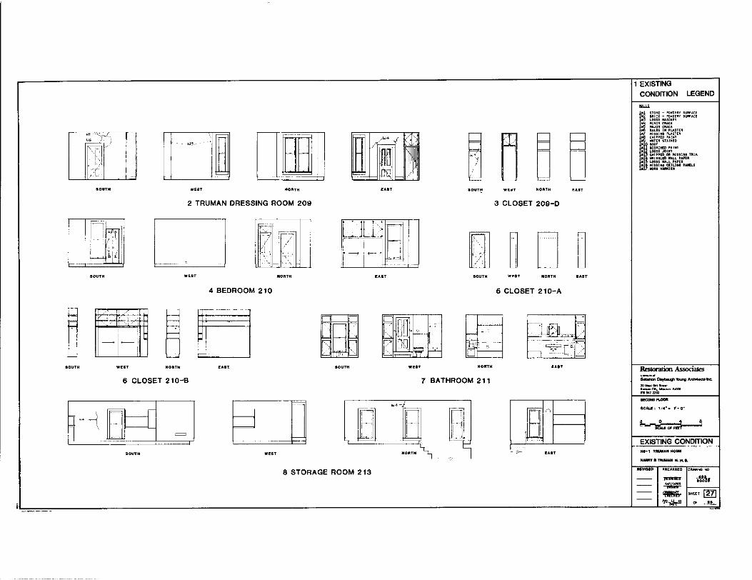
SOUTH
SOUTH
SOUTH Wl!IJT
[] lJD WEST HOllTH EAIT
2 TRUMAN DRESSING ROOM 209
om r= I!
I I-
~ -----" 'f--' I l ~ I
WEST NORTH l!AIT
4 BEDROOM 210
G ' . .
HORTH IOUTH
6 CLOSET 210-B
8 SOUTH WEST
8 STORAGE ROOM 213
1 EXISTING CONDITION LEGEND
3 CLOSET 209-D
LO SOUTH Wl!ST NORTH IAIT
5 CLOSET 210-A
WEST NORTH EAST Restoration Associates
7 BATHROOM 211
'FT'.' '' .--~ i-1
,'--' EXISTING CONDITION
'
l!AIT
1111\1111 ~REPARfD C""'"..cl M) ....... t.M. ~ - $1<HT [Ill -·.Ah" ~ _..._

2 LOWER LEVEL (NEW ATTIC) 302
=--- I
( ·~·
3 UPPER LEVEL (NEW ATTIC) 303
4 VESTIBULE 304
lj~
L..
wm
EAST
WEST
EAST
o= .
----
EXISTING
CONDITION LEGEND
I~ i~~~~ : ~,:g~~~ ~~:::~~ l•l LOOS! AASD•RY lw~ MINOR CO.C< lw> ••.10R <••" 1116 BULGE JN •LOOTER lw7 •I Sl,_r; >LA•TER lw8 <"IPPED "'"' )W9 WAT'" STAl•EO i•l0SOJT lwll SCD"HED .. INl IW12 1.00SEJ01"T lWB CHIPPED OR •ISll•G TRIH lwl~ WRIH•l.ED WALL •APER '"'! LDDSf WALL PA"'R lwl •JSSl•G Cflll•G PANEL• l•l •ORN VA•NISH
Rtstoratioo ft ssociates
s=;.°""*""'....,._h;. 20--.-c..-.. ..... ·-= scM.11!' ,,.. - f-o·
1 0 •
EXISTING CONDITION HS-1 'TMMAN HOME
tt.Ulll'f' $ YM*AN N. H.8,
REV18ED PREPARED 0RJ\W1..c; >fO
~ ... """ ~
'i!!!ill- SHEET ~ ~ ~ -"--

I I
'
' ' '
' ~~---y -·~/ ' -"-A-""- 0_ - "-
I LD -
rel • I"' ,' f--1
~-, I ~A m- -+- -~ -
,111- JII I
I ~y~a= ] 1 F-- - .. -- --I 31tl1~ !
7 ;- l I l\ =11 7 7 ' .l=I !~[" L _J
I ill ! I JlJ I. !
Restoration Associates ' I
! ~- -s=;~~....-..:i.n:. I! ,~11
~ llidl =.:'.~ .. .,, I 11:~
n~=
~ §
011 - --
SCALI!: 1"• 1'•0" JJ rn t\ ""' JI IL1r> ~ I 1c:& 5'1'1!1!'i ! '
lli
EXISTING CON>ITION .... ,.__ -ITMMIJIN.H.&. - PREP ... RED M-~
~ __..._ - -FULTO•
DETAIL SECTION THRU NORTH WALL 1 - ~
ICALI! : 1" • 1' • o• - 'il!li>- SHEET ~ - ~ • _.._
; . ·-~-' .
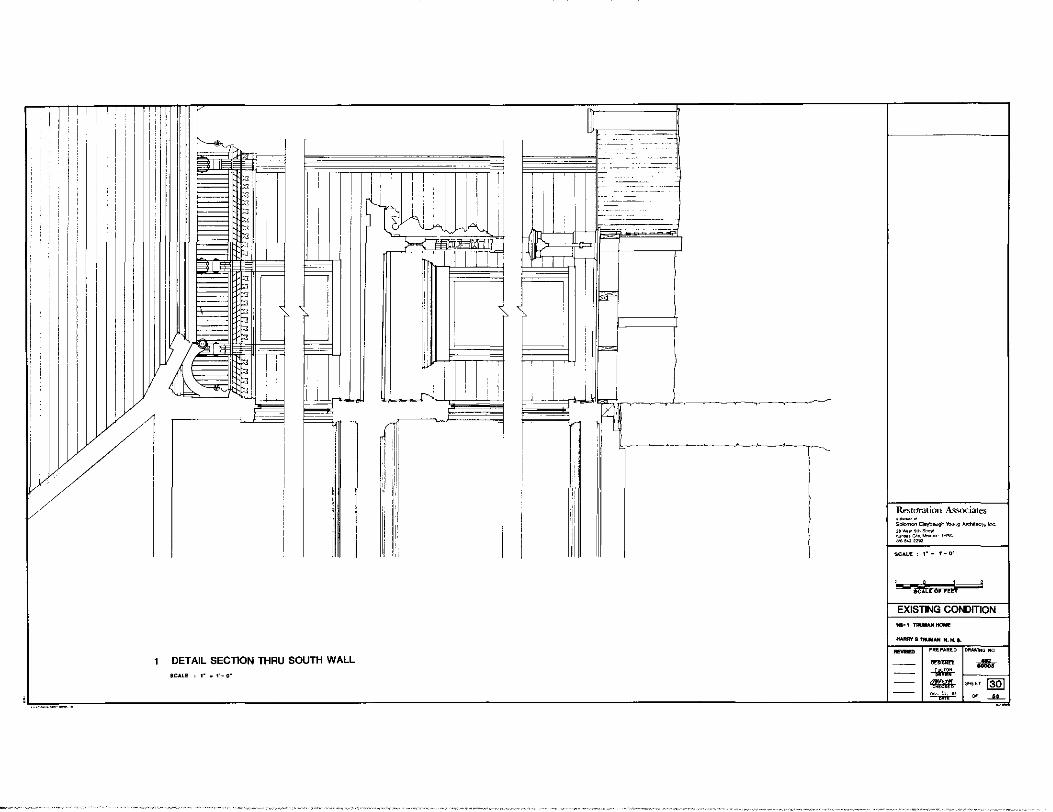
1ll''T 1
. I , !
i
I • ' : I 1, ' J
l]lL !!, T
)l~~l I f--
t; '
~ I
' l 1
ll I I I
l
. I , I I .
1 DETAIL SECTION THAU SOUTH WALL •CALE : r • 1'-0"
~ -- _:: ___ : :c_:_ - ::::
Restoration Associates S-..00~""'",g.o..d'vloc!>lnc
'""""""""""" ~":,~';',:;;,......,,..., "'"" SCALE: 1" • f'-0"
EXISTl'lG CONDITION
~ PREPARED DRA'lllNG NQ
- ~ -.lll!i-- -G:-- ~ SHEET ~ - '"'-"·" ~ _..__ ~ -
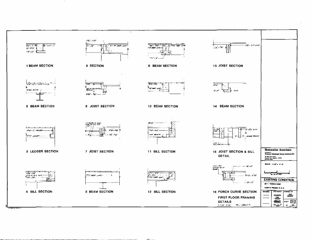
W<t'• ,, :,•, ,.•/+'
-:''J' .. i•--j==l
1 BEAM SECTION
b.,:;.;j ,i! J .. • ... T------.-+ ' . ~ ·~~·,,__, ,
2 BEAM SECTION
"T"ll''•t' -~----
~.,•·-1• -""""'"""'---
3 LEDGER SECTION
4 SILL SECTION
"''•Ii'>',
r_~cL-"-"='=i'.,_r
5 SECTION
•
6 JOIST SECTION
7 JOIST SECTION
8 BEAM SECTION
9 BEAM SECTION
10 BEAM SECTION
,i!o01.01<-------
11 SILL SECTION
~ ''I , ~~'1 ---i•, 1Y"- -1}'41 P!il'il' J.-1-Ff' ,
12 SILL SECTION
1;,i.',,~· - ,I'•' it=======i@n'i:-='===~1~ti', ,,,.,J"I"'
,!, \
13 JOIST SECTION
14 BEAM SECTION
15 JOIST SECTION & SILL
DETAIL
16 PORCH CURVE SECTION
FIRST FLOOR FRAMING DETAILS 1 112• 1·.o·
Rmora1ion Associates s:::.°"1b"'llll~-ft. ,._, ... ,,._. -00.-. ...... ~w~
11CALE,, v.r- T·o·
EXISTING CONDITION
HAlllrf8-N.H.S. - ~REPAREO """"l!IG NO
~ ... ·-· ~
'i!M!- SHEET ITil ~ ~ -"-
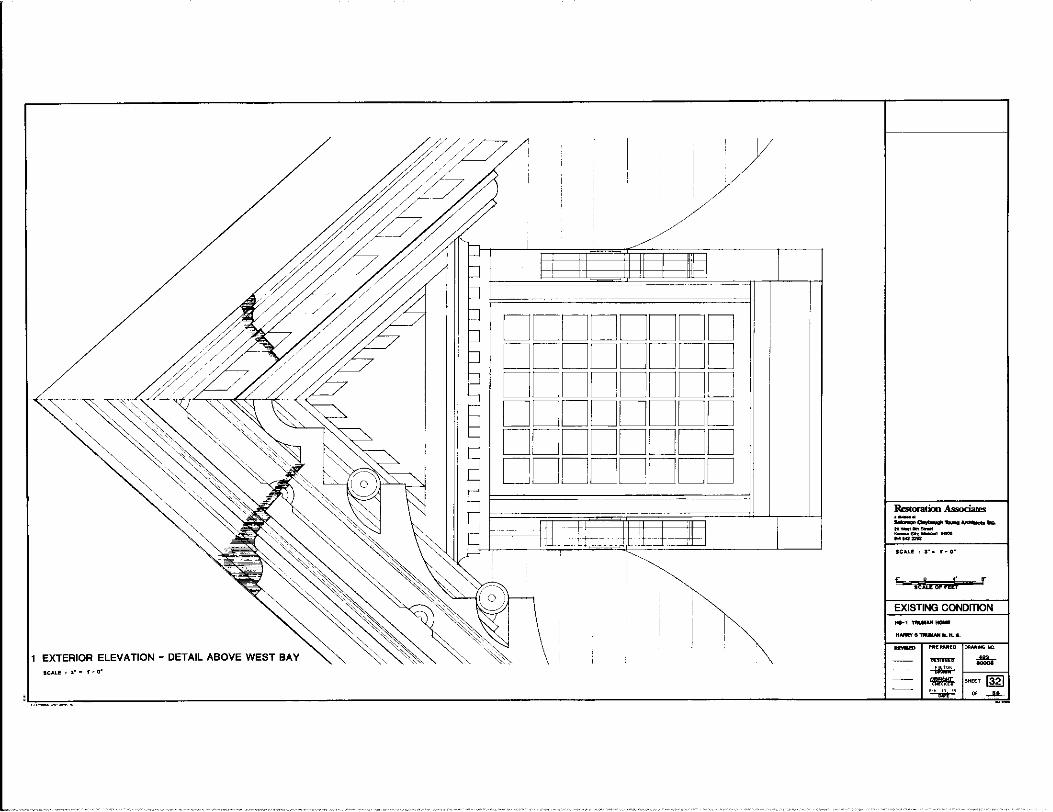
1 EXTERIOR ELEVATION - DETAIL ABOVE WEST BAY &CALE:~·- f~o•
DDDDDDDD DDDDDDDD DDDDDDDD DDDDDDDD DDDDDDDD DDDDDDDD
---~-.-loo. zo_...,_ -Clll<--"~-seA.L~, s·· r~o·
s .ch di' nli r
EXISTING CONDITION .... 1--~ illlM-~ f----1 ~ SHEU~ ~ Of ._l..L

--- _· .. ~ .. ~==I
EXTERIOR ELEVATION-DETAILS ABOVE NORTH BAY
f=-. 8CAU!: 3• - r-o·
$CALE: 3"· 1'·0"
0 J_ !I"
EXISTING CONDITION
REVISED PREPARED DRAWl"G !fO.
~SHEET~ ~ Of _u_
c::=- 0 c7
~----__j
f - ___ , --------! I
.. r\: I
... . 7
.? J
1 EXTERIOR DETAILS - WOODWORK & TRIM AT KITCHEN PORCH SCALE ' 3• - 1· - o•
-~'*""""-'""'" 10-.... --ca..---~-SCALE: 3"• 1·-0•
EXISTING CONDITION
llAflRY9~N.H.8.
~ ~ ~ 1---="1 ~SHEET~
~ OF __il_

w -----J -Will u uU
;:::: iJ
1 EXTERIOR DETAILS - WOODWORK & TRIM AT FRONT & SOUTH PORCHES SCALE: 3" • f·O'
:a:I
~ I \ \_
7 -~ I
2 FRONT PORCH BC ... LE : 3• • 1' ·0"
3 SOUTH PORCH SCALE: 3"• 1'-0"
Restoration Associates ·-· -~~--... .. _...,_ -""'-"'"'' n~-SCALE' 1·~ f·O"
EXISTING CONDITION 16-1 "TllUMANHOIE
H-S "TllUMAN N. II. S.
~ PftEPAllEO
~
~ ~ , .. "·" ~
DROllllNG NO
.:!1 SHEET ~ ~ --"--
- - J
1 MISC. SPECIAL EXT CNE HALF SCALE ERIOR DETAILS OF BRACKETS
{,, 0 ' SCALE OF FEET
EXISTING CONDI TION
HS - 1 11111NAN HOYE
HARRY S TIIUMAN N. H. 8.
REYISED PREPARED DRAWING NO

3 HEAD w' _,,,M--1'1"-'"'°'"ri: ;\O
4 JAMB
5 SILL
I
\ 6 HEAD
204:0-1 WEST
-n:,M Rt'. I+ Stll 'IO
W'
---r11:1M r~. ,~ .... -r . .ofo
l._____~t•· '~ I / I/~
7 JAMB I
8 SILL 002:D-112 SOUTH
10 HEAD
" hJI --- -- WI
'f!llM--- 1~1M re- I~ ~HT. 4"' IC~' 1-i~.rr.Ao
. 11 JAMB
FL1..;(F~f-4
12 SILL 109:D-1 WEST
w - ~'
13 HEAD
.JI-- -u-W' I
.
. .
14JAMi i r I 1"1.--~"-J/F'l
15 SILL 208:D-1 EAST
18 JAMB
19 SILL
--;RIM
20 HEAD
21 HEAD
105:D-1 SOUTH
~ n
wo----~l
22 JAMB
23 Sll.L 104:D-112 WEST
l-I 24 HEAD w·-H 25 JAMB
F"~; 26 SILL
113:D-112 WEST
"'
29 JAMB
f~1~/~ 30 SILL
103:D-2 $0UTtl
DOOR DETAILS 3":••-o·
1 SYSTEMS NOTES
"""" ~
.0 f!Nl!H ••!OT
f STOIN F~ v•RNl$H ~6 :::~~~.~~LLP•PU F7 ••L!-••••~ f8 PLASTIC T!LE
'~b t:~~~~A L< «•MIC TlLE
""""""" f[i ~~~:'-"'•••
~~ ~~~~:~i~r~~:" "•OD!OUD
~CY :g~: f: : ~: ~:~ :ggg Fee !R,CK
~
Bl HO !ASE 112 >CAIH l X "°OD
ff PlAIH IX •Oot> •1" ""UHD SHOE I ' WOOD •ITOP •l<llJLJ> QU.l"TEO ROUND'"'" CER""ICTICC
~
Wl ~:,:~~i~. •1"oon LATH
~ ~g=:~!J: l ! ~~HOOD ~ :1~~1' !O .... D YI E<POSED srou"u•E ve HOOD LM SIDIHG
U1 "" .... "'"I
Rtstoration Associates
SCAUh 3" ~ i·-o·
EXISTING CONDITION ttS-1 l'M*ANHOME
NMllYSTlllllU.>I N.H.I.
llEYltl!:D PREPARED OR•ING lfO
~ --"'-IOOOS
~ - SHEET !El ·~ ~ -"-
2 HEAD "' - -1
INTERIOR
5 HEAD
i I
6 JAMB
...ii---
7 SILL
EXTERIOR
002:W-3
"'""tJf ~f.e>~" . , 11 - I
BHEADM _ wo
::,"~~ ".
I '
10 SILL
INT!RIOll
i i
108:W-2
"''---..,,
i. 1
1 H:Elrl1AD-- _- --_ -' -
i ·: w' --
' i • I i 11 I
12 JAMe
13 SILL 106:W-2
I I
~~ HEAD~- lij _ -i}.'';!,-"11-~
- ' '
' -
15JAMB~ I
" -'{1 ~ 16 SILL
109A:W-2 •HTERIOll
w' -
!XTERIOR
17HEAD!l,' --'~ -_--_---"• I. .
,, WI -- /
I I i ',' i
" ,.~Jilt' 111
w• ~1 f 19 SILL
113:W-2
INTERIOR
w, ____ \
24 JAMB
~~~~C~I '~ 2 5 SILL
104:W- 1 EXTERIOR
- I ' -
I 1 i 'i·
201:w-1
WINDOW DETAILS a•,1·-0·
SYSTEMS NOTES
SCALl; a• i'•O'
HS·i TIIUMAN HOMe:
-·~M.H.S.
REVISED PREPARED DRAWi"° NO

0
STAIRWAY DETAILS $CALI!: a· - 1-o·
r"lr--1
p~
~ ~ _cf :
R Ill ~ I
,1
H il:1 Fl I= ' ~l~t
(
EXISTING CONDITION ltl•I TRUllAll HotllE
HAM'l'B~JC.11.8.
llEYlfl!I> PREPAllEO OR .... WG NO.
1 DOOR CORNER 101:0-1
2 CORNER BLOCK
3 CORNER BLOCK 105 20S
-'l,-4 CORNER
BASE
5 CORNER BLOCK •o•
6 CORNER BLOCK
9 CORNER BASE 100
11 CORNER BASE 101 102 103
107 108
10 CASING 201 2oa
7 CASING 1oa
8 CASING 10B
(
12 CORNER BLOCK 101 102 103 107 108
13 CASING 101102103 101
14 CASING 110 202 201
15 CASING 104
16 CASING 204
17 CASING 109
18 CORNER BLOCK 101 102 10, 107 108
DOOR & WINDOW
MOULDING PROFILES FULL SIZE
Restoratioo Associates b::.;;~'<blrog-\'>c. ,,,_...,_ ""'-C.,-..MU ~~=
FULL SIZE
EXISTING CONDITION H$-1 lllUOIAN HOlllE
IWIRVBTIUMNll.H.S.
REVISED PREPO.RED DRAWING NO
~ -""--'8000$
~ - SHEET ~ Fob 1'" 0, ---"-~
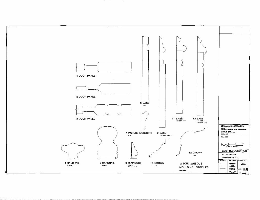
1 DOOR PANEL
2 DOOR PANEL
3 DOOR PANEL
4 HANDRAIL 5 HANDRAIL 202-B
6 BASE
"'
7 PICTURE MOULDING 9 BASE
11 BASE 105 201 20•
13 BASE 101 102 103 ,.,, 107 1011
"' 100 110 202 207
8 WAINSCOT CAP1u
10 CROWN
'"
12 CROWN '"
MISCELLANEOUS
MOULDING PROFILES FUl.L SIZE
-a.,bll'lllo .... -l'lc. il0-~-""'-•00.,-04100 ... 9411m
0
SC.0.LE OF INCHEs
EXISTING CONDITION HS-1 TRUMAN HOME
HAlllll'B~N.H.S.
R~ISEb PllEPAllEO DRAWING 'l<.l
~ _..,_ 80008
~ - SkEET ITil ... "·" --"--~
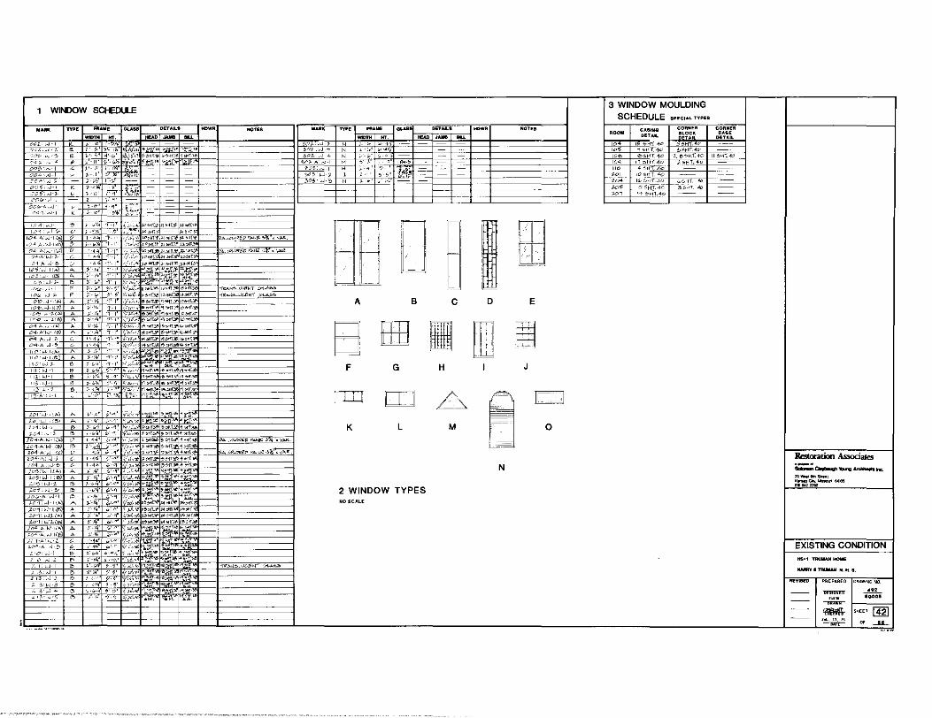
WINDOW SCl-EOULE
i<>"!AcJ /.
'''"'<-A "1-"' 110·>.J.1, .. ) 11<''>J•l.i!>)
ilO'L-.l .'-111: <-J-I 11i.w-1
1 13 LJ·I
<~ w 1 11"!:-A '.J
201..J-, ;..) h ~',<. (.'-'1 •0<1T·"'"""''"'_'jj[°-: ;_01·w ,,';) i'-4' iP''l' >""'-""~ ,~:.~0 n1.1-J-> !:> J'!.< i.>-"'l 1-·~T,...'l>Ol!T-"'+>tlf.3&
;:~~+;.~~~(>.) ~ ;~ :--~· \ :.-,! ::~::~~:': - "A-c<lOWP<'Mi~~}.i ,-y;._..~ ~~~-:-~- ~~ ~ ~-:·:~: ;' ~- -'.:::~:*;:n"~!~l';f"{~~·-,l-t---tM=M=-= __ = __ =,=.=.=,,=~~=,,=,=.".
•'=-'-;',===·=~=-='+-"'--1-;'-'-;';,i-c"''-'1' _;.,,<'b ,_..,,.-?',.~ .. "t-~ -~,:~."~-~~;:) ;. ~--¥- ~.-_:,'I ~~:~,.;.:;-~:~~ --U'5<W-l.e.) A i-4' -~"5'LJ·;I. B 1--0/~ ;:c,;_<-J-:!'> ~ :-~"I
,'D(,·A ..-.J·I /!> /-'•\>," ,cc1:e-1-1t;. A :1-·-1,,.· .Zo1·>J·1 ~) A 201: .-J1-i") A ;:01;..JJ..(e.j A
)<>'1""1-1(/. A
iP'-'1" ,_,.,_ "'"" ,,...,,., "''·9' !' "'· ~~ +•~T. <#'-'I' ,_,,.,. , • ...,..>C~-
0,'-9" .. . ,,, +_no. "''-4' ,,..,._ <ttn?- """"~ .;.-A "''*fl-"·M~t;;,,.rT -· 9 ..... lt',•><'11.>l>~~>Hl. (.;.' 'JOdlc >~M;rlf,l.O 5St1f."' :;.'"l '(,d,.., , .. ,...)F,6 "''"
b-'1 v ,~, o+ ,__.,,, '/.;',,,,
ii>'-'l' y,/,~ + ~ ... ,, ,,; ~'". 0.-9'1>' ',C.• f-5' "/"-'·'° ,,
r:r. ~: V"')' O« ".>'-"')' [L~· . .,,'
1------j
A
B F
TTlJ
K
G
'I IJ
B
DJ L
2 WINDOW TYPES NO SCALE
NOTU
=:t----::il====- -I
- ----I
c D E
H J
0 M [l -
~
N
3 WINDOW MOULDING SCHEDULE SHCIAL TYPES
CASING DETAIL
I SH 4" ., .. >+-r.'+c e>M-<T_ '!-.:?
11 'OH'l'. 4D
14 "'". 40 "'-'dT. .<o
CORNER BLOCK DETAIL
6H . c ~~H'T'.4<>
i. e"'M .+o )._C".HT.4o
CORNER 8ASE
DETAIL
--1 Iii> -;,,1T.AC b' HT "o
:~ ;~;~ !=-~·~;~~=· =~°::1·==~~~~=5
Restoration Assoc:iates &:::a.,i.v.'ltu>g -1-c. ""---· ==~- .....
EXISTING CONDITION
KNIRY 8 TRllllAN N. H. 8.
~SHEET~ ... "·" ~ ~ _.._

DOOR SCHEDULE
·- """ LEAF llATl!FllAL DETAILS
-- lfT. THK. DOOR FRAME HIW) JAMB $LL. ()()1,. '701 3' ~· ~-1C' J::1'., L-1~ ~, .. 1,.- 10~1'1 Miff.;-,
001,.-,,-;1. "" ""1- oOI ·-~· .;·,c ,;-..,• L-.P l,.J" ,,,_~1:-;,T;HT.,1,;"-11'1 OO"!J'P·I N 170'11 C>01 :l. r. ., . .,v~ -y.,• """ wt>
00-t:o-1 o: "'""' oo5"I£·o' "'-Y 1;., L-lr' -J~ _
10l'P·MS) (, IOI ,,,,_ .1- ... .,_., ~/. WO'-""'~ ·~...-r.Y11•••'-•" ii:r><l<P:.c ........ 1oi DI Po<<•T •OJ- 104 Wr' .JP N"N~LJNCTl"..J .. c,£,CEVLI,.;KNo~~
103·17.1, .. ) """""' 10!> @..i!: WV ,j, N?N~u""-11o""" fch'.cH~"i<'OC"1
1-e: ~;i~c·•ge: ~c"c' e~eOe~Cif-C: ~;,,;;.+o', 0,, g,,.,., .. "•""•"'"'c'7'C·rle~c'c;-f"~c"o:-ic,,c~c,+,c, ~~,+,,c,c,c,", f."N;>• ~UN~'"'~ Ac tcEv J>KNDW ol
10"1:?·1 F' 104 10•M~ J--1 !>'·•' IY< WO' l-.JO !¢>Hf,>' ""'""n~i:;~ fuf.6_).)<01'-Wf ..>'--"'6"' - -- -
lll~P·l ill 1•0 1-' o;.'·1' l'/t," WP'"°'" n ,._,,,., '1
11:<-D·I & 1-1~ ii'IA :t'·e>"r.'·1 I' L.JP WO+"''""'""'" ><t\1
11~'-D·J f' 11:'> 11'1-,o, J-'·1 .. -.~~J3> W" WO """l ~>«l'1 ,.,,,_,
::;:g:~ q ::~ :,'~.~ i'.:i~·~··~· :~1• ~~ ~~ ~ .. '11+...r.,,,,.;;;~
1-D~ :p·I ~
J-o .. . <' 2- A
J_D~; !7·1 !':' :J.D'l.O·I A ::t-:R_I.p-J- A
:>-00,P·I A JO'b:t:'-:t A ;..:>'! p-' i-10· i;>·I ~
i-10· P·J
i-10 "'-'
i-10: "'"' I<:.
Jot- J.d,1.-c. i'-1.' .;.·-s 1v.., w;:; w<' )._02- :Z"'""" P·" '°'°"'' I'•' 1.-· ._.iv
.
trtxt-f=t . ·. t . . - -t----t--j--+
-r=-::t::-::::t::::::t::=t:
·
-
··-
--
--
--
A B
J
N 0
2 DOOR TYPES NO SC4LE
~--
1
.1 1 i !
m 1 '
.
c D E F G H
[Lo - .·--1 .. 11- I [d .. ·./' ... ' O_D '/' I ;/,
K
p a
L
R s T
3 DOOR MOULDING SCHEDULE SPECIAL TYPES
CHING i~G~:R DETAIL DnAIL
IOI 1? '° 1. -4<1 <i 1e> "'" . !Ot- 13 51-!T. ,fa IJ, It> 6.-!-f. 10~ 1:0 ,,H"f, -'fO I;!. 1E> .5H'l.-!a I".. 1-S "'H1. /rtJ :::]'.<>K1,3 10 --i<>H1.-w ~~i-;r. ~
'l-<>S IO !>K-f. 40 z.o--i 1+ :'>'1f. 4"
CORNER B4SE
llET41L
11"4-1~ 11 srrr . .+0 11 "'H'f 40
M
Ri.ostoration Associates =.-;~ ..... --h:. i!Cl-"'s.""""'c.,.-..eo ... ~w
EXISTING CONDITION
HAllllYSTIUU.NM.H.8 .
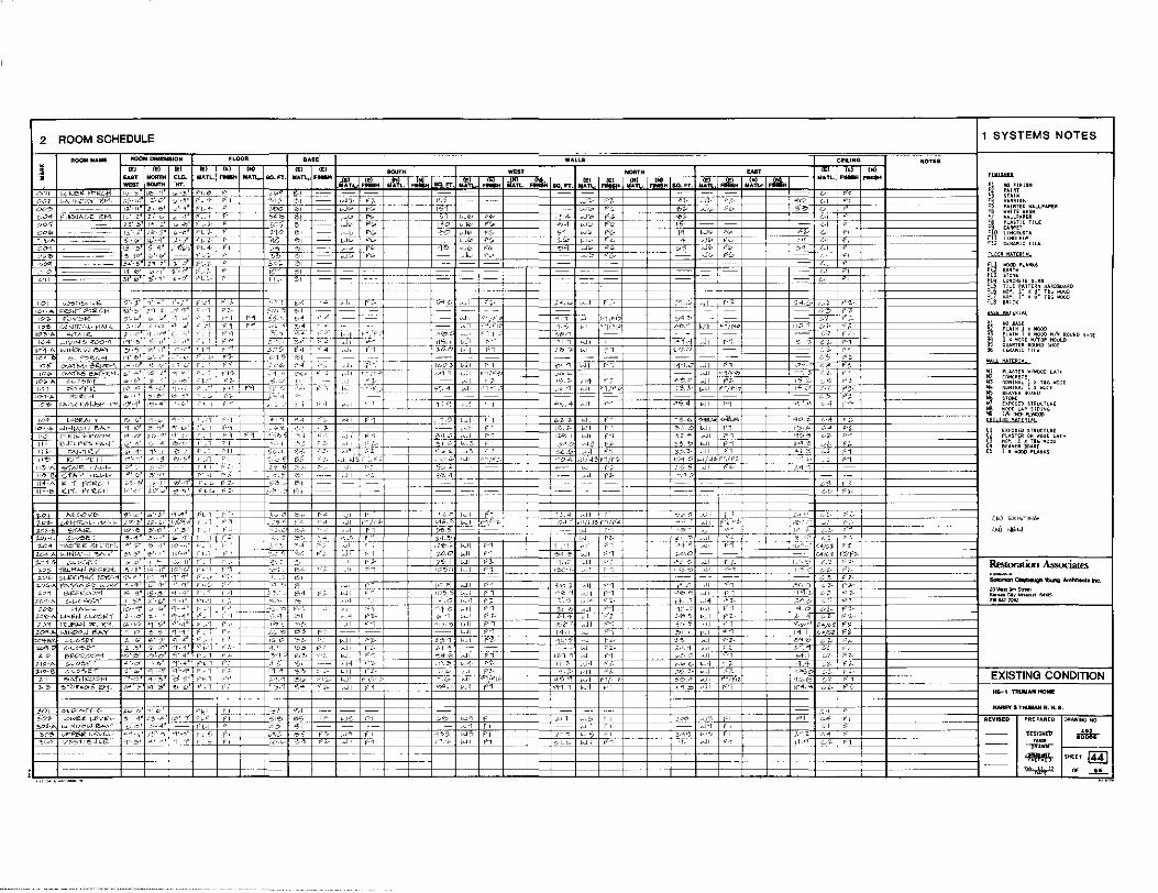
2 ROOM SOHEDULE
ROO.O NAlllE
! 001
10~ l-•BI'-"' y l<>'j-,0, ..Jl>JpOIJ t'.>/>..Y
I•'-" r"Hli-J'-"F?-°OH i 11 E-Jlt->'i'"- c,,;.t...j/ 1,1' r'At~1<'.'._Y
''~ K,_.,..,,~-li
11?>-A ?"\A'«' .<l;L-L--
11!>-IO> <;."!'A.· H:..L-<--114-A Kl-f. HR!-11 111·<0 l(J1. P<.:CC.11
., ., •• ~-= WEST llOl,ITH -HT.
FLOOR
!ti CE)
NATL.-
1-7 ·b'-•l ,- ,_ '-' F' 7-
BASE
H n'~ 'O·'.:'c'+~'c'""r'""'--+--+:2':~c'+'~+-+-~--+--+--+--+-
; •. CJ f·-1 '.JI
W,t,Ll.8 Cfll.ING
- --(..,. f l
--:.-~· Fl--y-
.!-4 ~J1
··-~ ~~--.:,c,·· C"- eJI
-.;. ~ ,.,,; '"' ~--+""' c' --r' Wc"",'""r''c~!e~c·~-+--~"c~c-'cf-''JI_ P:·i_'.'' ... ~/ ·1 ~:
~;:c
~og W•NDeo.-J ll\A,
!>C'"!> iJPP!'-1". l-<'Yf-l--
~I'~"!-!>'-/- 1£'_'._ f >L" O --o' "'-4 FL-I ''4-~, J-~· "-' 4'0 I l 0 ,,
,it;.~ kJI f'-"1
'/-0.0 WI f1 7'5.I WI F'J.-1,?':):: 1-JI (·_"}
& -1 .__,___, /_,-
f"
rT
" t--1
','i'O I- ~JI
"<?o '1 ~JI
'0 ,-i« 5C V ,ji i'L<j- -·,-
MECHANICAL SCHEDULE
ROD~ !!AM
•I
2 PLUMBING RISER DIAGRA MOBCAl..C M
'" ~~
lo«r '""'
LAUNDRV <OGM002
00, ..... !M""""" o.rES
!~~""""" GATES
!~~··-'"""'' ~ar-
~n""""" ~l"""°"
ttI"""""
COLOR }jHITE
COL.OR-GREEN
COL.OR-GREEN
COLOR-GREE•-
COLOR GR!<H
COlOR-llUE
COlO~ MSlfR ONE PCE~
___J
I
KB-1TlllJll ION AlllfOMI ---j
HARRY S TillmAJI N. H. IS.
REYllll.D PRE,..,REQ DRAWINGNO ...
80005

III. Existing Conditions -- Truman Carriage House (HS-02)
Introduction and Description
This white, 1-1/2 story, heavy timber framed structure with a shallow
limestone foundation, measures approximately 24 x 32 feet. Its date of
construction is unknown, but probably dates to the late 1860s or 1870s.
The barn was adapted as a garage before 1914 to house the Gates' auto
mobile.1 The gable roof is sheathed in dip stained wooden shingles and
crowned with a louvered square cupola at the center of the ridge. A
gablet is centered on each roof leaf at the eave line. The south gablet
features two loft doors. Loft doors also exist at the main gable ends.
Two siv-pane fixed windows and two shuttered openings mark the east and
west facades respectively at the ground floor. The structure has a
concrete slab floor. Overhead rolling garage doors enclose the two-car
bays. Vertical board and batten siding is the predominant sheathing
material. (See Figs. 3.1-3.4.)
Topography
Drainage around the structure is generally very poor. At the south
elevation adjacent to the alley, soil and gravel has been built up to
obtain positive drainage away from the Carriage house. Unfortunately,
the exterior grade now rises above the interior grade of the concrete
floor slab. This has led to severe deterioration of the siding,
foundation sill and structural post bases. It appears that the exterior
grade has been raised at least 20 inches along the south elevation with
- 97 -
layers of refuge waste, gravel and soil.
The west elevation shares some of the same problems as the south
elevation. The soil has been built-up 2 inches above the top of the
foundation wall. Tall, thick bushes along the west elevation have
compounded moisture problems by reducing ventilation and sun exposure.
The only downspout on the building drains rain water at the northwest
corner. Negative slope causes water to pond in this area.
The sub-structure at the north elevation is completely encased in
concrete slabs. There is good drainage from the structure here.
The grade along the east elevation is approximately 1 foot below the top
of the foundation wall. Moisture problems are not apparent; there is a
slight slope away from the building towards the driveway. 2
Foundation Wall (See Appendix G.)
During a 1985 physical investigation of the foundation, several pits
were excavated to determine the condition of the wall. The foundation
wall was found to be of rough cut limestone laid up in a soft lime and
sand mortar. The depth of the foundation wall is 24 inches in the
eastern half and 30 inches in the western half. The thickness of the
wall was not determined and no spread footings were found. It is
unknown whether a foundation wall supports the interior partition and
posts 3, 4, and 5 as a concrete slab was poured over the entire interior
- 98 -

floor surface in the mid 1950s.
The stone foundation is in good condition overall. However, there are a
couple of deteriorated areas which must be addressed. At the northwest
corner, there is practically no bearing beneath posts 1 and 2. The top
12 to 18 inches of the wall had been removed presumably in the repair of
the posts, but was never rebuilt. Post 1 is supported by a fragment of
concrete block and post 2 has no bearing at all.
A few top stones have been moved out of alignment at the east elevation.
The stones appear to have been pushed out prior to the concrete slab
installation.
The entire south and west foundation elevations are backfilled with
soil. However, the foundation wall is in good condition at the sample
pits. 3
Foundation Sills
The foundation sills throughout the Carriage house are severely
deteriorated. (See Fig. 3,5,) Two contributing factors for the
deterioration are poor grading and the interior concrete slab. The slab
had been poured over the sills using the interior surface of the siding
as a form. This construction method entombed the sills allowing no
escape route for moisture. Rotting is so extreme along the south
elevation that little could be found of the original sill. All of the
- 99 -
sills have lost any of their structural bearing capabilities.4
Garage Floor
The concrete floor is a later addition to the facility and appears to be
a 3 to 4 inch overlay covering the original floor. The ground floor of
the eastern portion is constructed of hand hewn heavy timber pests set
over a 4 x 6 inch foundation sill. The western addition is of dimen
sioned posts set over a 6 x 6 inch sill. The concrete floor was poured
around the vertical columns and external siding such that it covers the
original connections to the foundation~. 5 Because the bases of all the
posts are in poor condition, it is difficult to determine connective
systems. Along the north elevation, it is possible that the steel
garage door track channels are literally providing support for those
posts at the south and north elevations. Also, it is assumed that the
tongue and groove siding at the south elevation now plays a major
structural role in supporting posts 11 through 14. 6
Floor/Ceiling System Framing
As was evident in the Truman home, many of the joints were found to be
of mortise and tenon construction which, although considerably high in
craftsmanship, greatly restrict the ultimate strength of the' ccnnecting
members. Beams are found to be high in bending mcment capacity bvt weak
in connection shear values. It will be important to limit the loading
of the, loft floors. These areas should not be utilized as temvorary or
permanent storage for anything other than what is now present.
- 100 -
It should be noted that the loft floor on the east side of the garage is
approximately 1-1/2 feet lower than the loft floor of the west area.
Probably due to the addition of the west bay to the original east
structure, the additional vertical elevation required on the east side
to construct the roof at a uniform level causes a discontinuity in the
structural framework. This could be subjected to severe lateral
pressures. 7
The southeast corner of the western bay of the facility shows evidence
of a fire which has charred the floor joists of the loft area and
several of the vertical eastern and southern wall members of this area.
This burned area affects the first seven joists as counted from the
south end of this area. The charred areas effectively reduce the cross
sectional dimensions of these members from 2 x to 1 x material and
reduce the height of the joists by a minimum of 1 inch. This greatly
reduces the cross-sectional areas and section modulus of these members.
The lost decking in this area is also charred, thus reducing its
8 strength.
Roof System Framing
6 x 6 inch horizontal members cap columns and separate vertical 6 x 6
inch members and continue upward from the horizontal member to support
the plates upon which the various roof rafters are set. Probably due to
the addition of the west bay to the original east structure, the
additional vertical elevation required on the east side to construct the
- 101 -

roof at a uniform level causes a discontinuity in the structural
framework. This could be a serious concern should the structure be
subjected to severe lateral pressures. 9
Roofing Materials
The roof consists of a single layer of wood shingles, stained green.
The roofing is approaching the end of its life expectancy as evidenced
by lifted and curled shingles, missing shingles and water stains on the
underside of the roof sheathing. The ridge is covered with a sheet
metal hip roll. Where the gablets intersect the main roof the valleys
are the open type, uniform in width, and flashed with sheet metal.
The cupola is capped with a cross gable roof covered with wood shingles,
stained green with closed valleys. A bronze wind vane surmounted with a
figure of a horse in stride is located at the ridge of the north gable.
A continuous 5 inch K style galvanized metal gutter is located along the
full length of the cove at the north side but stops approximately 18
inches short of the west end which allows rain water to drip onto the
ground causing soil erosion and splashup. The gutter is fastened to the
fascia with spikes and ferrules and where it spans the gablet it is
supported on two simple metal brackets. The brackets exhibit some
oxidation resulting in rust stains on the siding below each one.
A 4 inch diameter downspout is located at the west end of the north
elevation and connects to a 6 inch long horizontal section which empties
- 102 -
directly onto the ground. The lack of a splash block, a loose con
nection between the downspout and the horizontal extension, and the
gutter stopping short of the west edge of the roof are causing soil
erosion and deterioration of the foundation wall at the northwest
corner.
No gutter exists on the south elevation. Lack of proper roof drainage
and site grading which is sloped towards the south wall instead of away
from it has caused the lower ends of the siding to decay. A gutter and
downspout should be installed on this elevation and the site regraded to
facilitate drainage away from the building.
Wall System Framing (See Appendix G.)
Vertical structural members consist of 6 x 6 or 8 x 8 wood members.10
The bases of all posts are generally in poor condition. (See Fig. 3.6;
A, B, C, and D.) Deterioration causes are the same as with the
foundation sills. In addition, there is evidence that termites have
also contributed to decay. 11
The vertical structural members of the eastern bay extend through the
floor of the loft approximately 2-1/2 feet. The column adjacent to the
west opening of the garage door within the western bay was found to be
suspended. The column is basically supported at the base by the garage
door track which is bearing on the concrete floor of the bay. The angle
brackets which originally supported the track are now supporting the
- 103 -
column and are showing bending stresses due to this loading. The column
adjacent to the west, although not having ideal foundation bearing, is
supported and appears to be carrying the vertical loads of this corner
of the building. The easterly wall of the Carriage house appears to
have pulled outward to the east from the existing slab by approximately
1-1/2 inches as may be evidenced by the voids in the concrete slab
previously filled by 2 x 4 vertical members. This movement may have
been caused in part by the fact that the entire garage assembly leans to
the east approximately 3 inches as measured from the upper plate of the
garage to the base at ground level. The stress in the east wall caused
by this movement has been partially relieved by the base of the wall
k . k" 12 ic ing out.
Exterior Envelope and Finishes
Some evidence of rot and/or termite damage within the lower areas of the
western and southern elevations of the structure was noted. The
exterior surfaces of these sides are relatively close or in direct
contact with the surrolinding soil causing severe problems with regard to
drainage and subsequent moisture and insect infestation. This is an
item that should be remedied as soon as possible as the ultimate damage
done could be severe. The exterior sheathing of this structure is the
main structural item resisting lateral stresses. As deterioration of
the lower portions of these boards takes place, the lower connections
lose effectiveness thus seriously eroding the structure's ability to
resist wind loading. 13
- 104 -
The Carriage house is sheathed in 3/4 x 11-3/4 to 12-3/4 inch board and
batten siding or 3/4 x 3-1/4 or 5-1/4 inch tongue and groove14 wood
siding painted white. The east and west elevations are sheathed en
tirely with board and batten. The siding on the west elevation is in
fair condition. The lower edge of the boards has decayed because it is
in contact with the soil, a few battens are split, and a portion of the
first board is missing at the southwest corner. Otherwise all boards
and battens are intact.
The siding on the east elevation exhibits numerous open joints and
missing or non-original battens. Relative to the west elevation, it is
in poor condition. The edge is not in direct contact with the soil and
is in sound condition.
North elevation wood siding either side of the overhead doors is 3/4 x
5-1/4 inch tongue and groove placed vertically, while the siding above
each door is 3/4 x 3-1/4 inch also placed vertically. The tongue and
groove siding extends approximately 9 feet above grade to a simple
square molding or wood drip. Siding above the cove is board and batten.
The siding on the south elevation is 3/4 x 5-1/4 inch vertical tongue
and groove extending to the same height as the north elevation capped by
a metal drip or simple square molding. It is sound except for the lower
6 to 10 inches which is in contact with the ground. Above the tongue
and groove is board and batten siding.
- 105 -
The cupola is clad on the east and west sides with 3/4 x 5-1/4 inch
tongue and groove wood siding placed horizontally. A horizontal louver
forms the north and south elevations.
All siding and louvers are painted white. The paint is peeling and
extensively alligatored and crazed. Paint should be hand stripped from
all exterior surfaces and new paint applied.
Windows
The west elevation has three shuttered windows, two placed symmetrically
approximately 3 feet above grade level and one centered in the gable.
The two-panel, louvered shutters are in the closed position. The
shutters on the two lower windows are painted green, whereas the
shutters on the upper window are painted white. Originally the louvers
rotated but because of the build up of paint layers at the pivot point,
the louvers are immobile. The condition of the shutters is poor. Round
pegs have worked loose from the mortise and tenon resulting in loose
joints where the lower stiles engage the bottom rails. Paint has peeled
from 30 to 40 percent of the shutters and the bare wood has weathered
grey and exhibits substantial checking. The hinges, two for each leaf,
are heavily encrusted with paint.
Window casing at the jambs on the west elevation is plain wood 1-1/8
inches thick x 4-1/2 inches wide. The casing at the head is an unbroken
pediment capped by a simple crown. The lower portion of the crown (cove
- 106 -
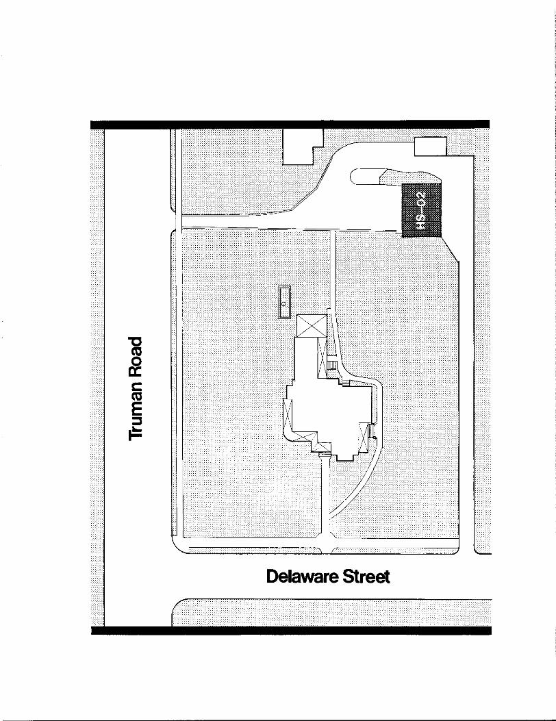
J c: ca E ::::J i=
Delaware Street
molding) is missing from the pediment of the north side of the north
window.
The sash at the loft window is double hung, six-over-six light, painted
white. The upper sash is boarded over on the interior with nominal 5
inch tongue and groove boards. Only the frame is extant on the lower
windows, the sash having been removed previously (date unknown). The
frames are boarded over on the inside with nominal 5 inch tongue and
groove siding.
The casing and sash at the lot window in the gable of the east elevation
is similar to the upper window on the west elevation except that the
upper sash is boarded over from the exterior with nominal 5 inch tongue
and groove boards. Although the east lot window is not presently fitted
with shutters, they were installed at one time as evidenced by remains
of a hinge that matches the hinges on the west elevation.
The two lower windows have no finish framing or casing. Openings were
cut into the board and batten siding. A single three-over-three light
sash, painted green, rests on a 3/4 inch wood sill and is held in place
with wood stops top and bottom fastened to the structural frame. The
sills of both windows are severely checked and slope inward. The bottom
rail and lower portions of the stiles are in poor condition.
- 107 -
Doors
The door at grade level on the east elevation consists of 3/4 x 5 inch
tongue and groove wood boards fastened to a wood "Z" frame, and has two
strap hinges secured to the siding boards at the south side of the
opening. Like the windows, the doorway is devoid of casing and a
finished frame. The top of the opening lacks any drip cap or flashing
to protect the top edge of the door. Three siding boards adjacent to
the door on the north side are loose and require refastening.
On the south elevation, two doors provide access to the loft. Both
doors are board and batten and appear to be cut from the wall siding.
The openings are without sills, casing, finished frame and drip cap or
flashing at the head. The doors are secured with strap hinges and open
toward each other. The west door is missing half of one board and one
batten. The lower ends of the boards on both doors are split, checked,
and require repair.
The two 7 foot x 13 foot 8 inch rolling overhead doors on the north
elevation are in good condition except for the lower roller guides and
pulleys which exhibit surface rust. The garage doors are paneled with
the top panel glazed and are painted white. The doors are binding due
to the shifting of the structure.
Interior Finishes
The interior is of severely peeling whitewash. The wood siding, both
- 108 -

board and batten and tongue and groove exhibits minor water stains at
the joints but is in sound condition.
The ceiling joists and boards are painted silver. This paint was
sprayed on, evidenced by thin coverage on boards not damaged by fire and
was done presumably to seal the wood charred by the fire.
The loft is unpainted except for the vertical siding at the change of
floor levels.
Electrical Service and Systems
Service to the Carriage house was run underground in 1985 from the
Truman home. The original aerial conductors from an alley pole have
been disconnected and left in place. The Carriage house utilizes wall
switched overhead porcelain incandescent fixtures.
The building appears to have had four electrical systems, the oldest
evidenced by four evenly spaced holes, inside and out, of a size
typically used for porcelain tubes and screw-in insulators. This is
located on the south wall. Wiring was probably knob and tube. Still
extant is a set of safety switches on the south wall with a cut-off
ground wire and an armored cable to an inside junction box near the
center of the west wall. This has been disconnected.
The third type of electrical service is the existing aerial line to the
- 109 -
porch corner. This service was disconnected in 1985 when the Carriage
house was rewired. Also extant, but disconnected, is an Independence
Power and Light temporary service line.
Security Systems
The Carriage house fire and security devices, installed in 1985, are
tied to the main house panel. An intrusion alarm utilizes infrared
motion detectors inside the Carriage house and at the southeast corner
to monitor access from the alley.
Fire detection is accomplished with heat detectors and two types of
smoke detectors: photo-electric and ionization.
Historic Security System
There is evidence of an historic electric-eye system across the driveway
evidenced by holes in the siding at the southeast corner and interior
shelf. There is also an exterior box at the northeast corner and aerial
wire from the northeast corner to the tree next to the Wallace house.
- 110 -
Notes to Chapter III
1. Ron Cockrell, Historic Structures Report: History and Significance, Harry S Truman National Historic Site, Independence, Missouri (Omaha: National Park Service, Midwest Regional Office, 1984), 341.
2. National Park Service, "Physical Investigation Report and Treatment Proposal, Truman Carriage House (HS-02) Foundation, Harry S Truman National Historic Site, Independence, Missouri" (Omaha, Cultural Resources Management Division, 1985, photocopy), 1-2. Hereafter cited as "PIR (HS-02). 11
3. Ibid. , 2.
4, Ibid., 2-3.
5, Lawrence S. Graham, P.E., (Kansas City, Harper and Kerr July 26, 1985, photocopy), 3,
6. PIR (HS-02), 3,
7, Truman Garage, 2.
8. Ibid., 3,
9, Ibid., 1-2.
10. Ibid., 1.
11. PIR (HS-02), 3,
12. Truman Garage, 1, 3,
13. Ibid., 2.
14. PIR (HS-02), 1.
"Truman Garage, Independence, Missouri" Consulting Structural Engineers, P.A., Hereafter cited as "Truman Garage."
- 111 -
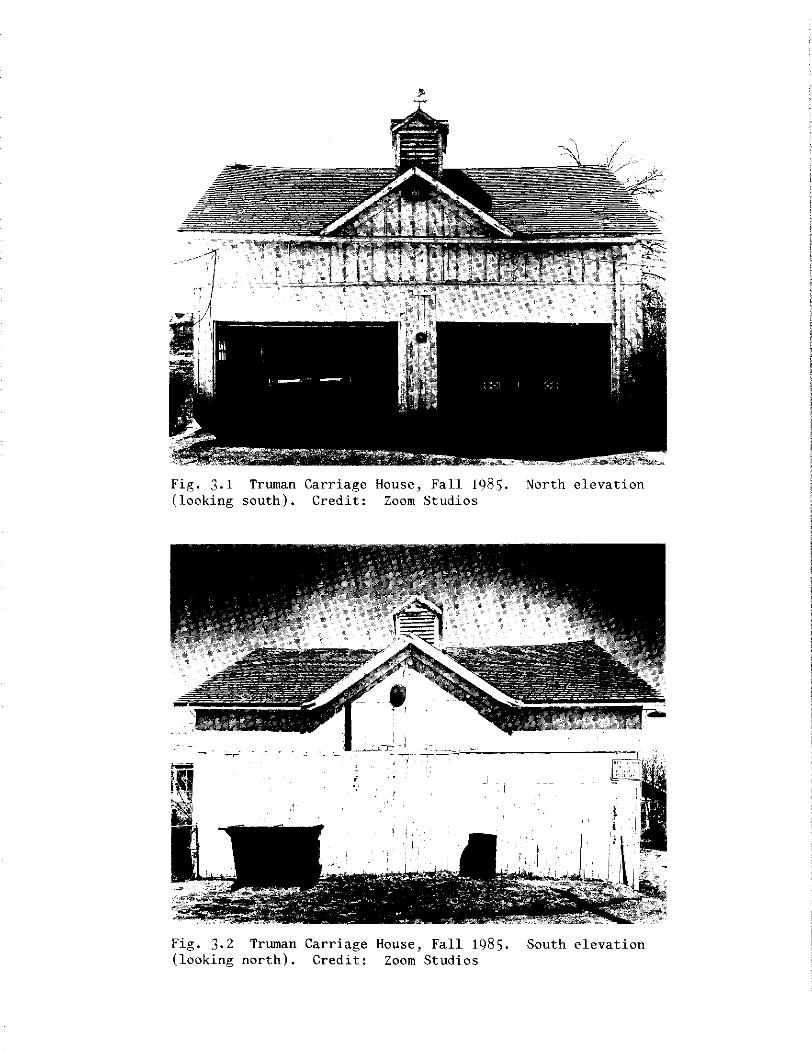
Fig. 3.1 Truman Carriage House, Fall 1985. North elevation (looking south). Credit: Zoom Studios
Fig. 3.2 Truman Carriage House, Fall 1985. South elevation (looking north). Credit: Zoom Studios
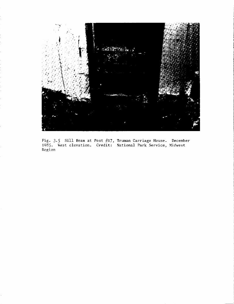
Fig. 3.5 Sill Beam at Post #17, Truman Carriage House. December 1985. West elevation. Credit: National Park Service, Midwest Region
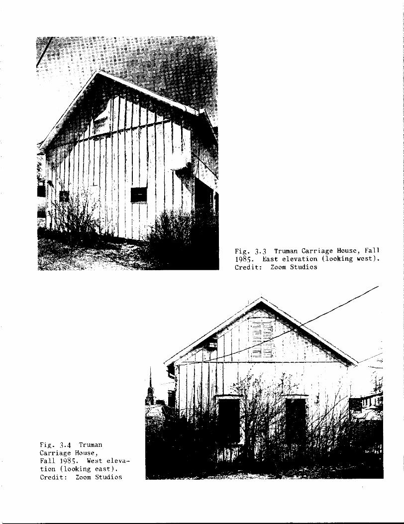
Fig. 3,4 Truman Carriage House, Fall 1985. West elevation (looking east). Credit: Zoom Studios
Fig. 3,3 Truman Carriage House, Fall 1985. East elevation (looking west). Credit: Zoom Studios
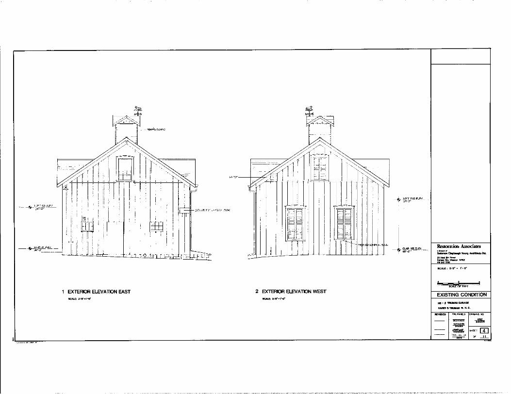
Rt-storatior1 Associaces ·-· -~brig-~
~-·-..... Clr)o.--~~-
?
SJli Of' FEET
EXTERIOR ELEVATION EAST 2 EXTERIOR ELEVATION WEST EXISTING CONDITION
REVISED PREPARED ORAW~G HO
~ ~ ~ - S><EET m ""-"·" ~ ~ -"--
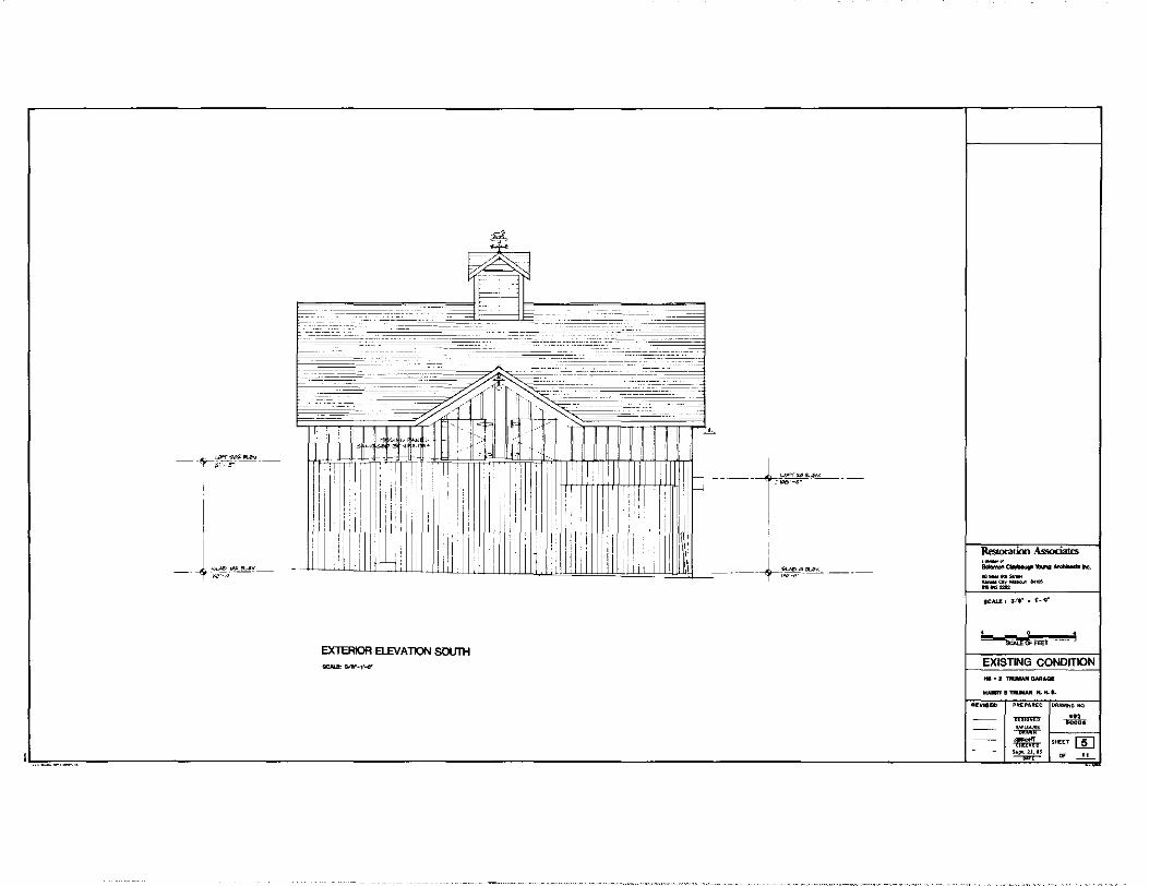
---· j""--Rt:stora1ion Associates ·-· -~ .... -no. 20-!l<h--or,-.<1$411)< -~=
SCALI'• 3,-.•. 1-o·
' - J
EX1ER10R ELEVA 1lON SOUTH EXISTING CONDITION
llil'vll!D PUPAREO DRAWING "'3.
""""' .::i. ~ ='I,- SHEET []] .. ,._,,,.,
~ _,_,_ ~
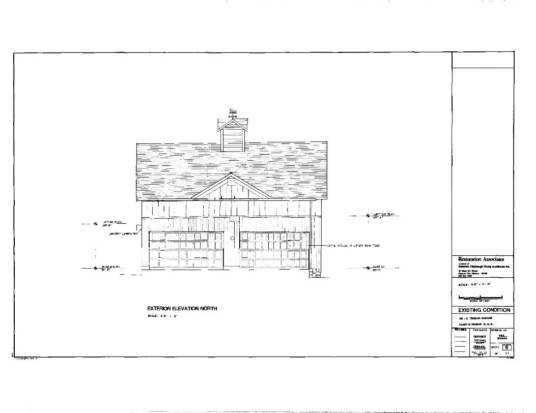
I
I I - _l
I!' ! ! !2=J~7DDDD LJ~[~DDDDDD =I- oo:=o_:_Ji_ IL I 0_[ L l r IOP,,_'-tt-tttt-~--, ''"'' "°'"' ' 0
""0
"
- r~----:11cJJ_JLJ I o::_LLoononn : 1
f:::J:=j=i ==·=~=-=~=='c=-=:"/ '=-='=-=ll=L=:="~:-=~'=c='=i=i~=, I=_ =l'=-=·=-[=J~L=--=,J=!J=·=i~ !
Rtstoratioo Associates ~~~-hi:. Ml_.., _ _ ,,..,-.,..,.. nw=
SCAU: 3/B"•-1'•0"
SCAii &FEET EXTERIOR ELEV A TION NORTH EXISTING CONDITION 8C4LE: 318' 1 o·
PRE .... RED Dl<AWI~ NO
"""""' _..,__
w•- eoooa ~ -- SHEET []] .... "·" ~ ____!,!--~

IOIJTH
I . . ......
tcJ0CJl2JLJLJ[l1JLJLJ I· p fT lr lllrlrll lrTlrTl
1,
' l:ll:l l:l Ll u l:l l:l l:l l:ll:l ![ 1]r-inn1 1011r 1n
2 GARAGE BAY 101 SCALE: air 1 Cl"
' ' I
" 0 '• ! ' " ILJ; ,,
' i
IOIJTH
3 GARAGE BAY 102 SCALE: 118" • 1'. o•
:J[ r::J[_ fl[
1 ',,' i,I I !' '' ! ' "
il' ! '[; I
I
,J '.ci. 0
:,1~f : ,,,, - I
• i ' :
...J. W!8T
OST
.ID[ ::J[ :::J[ ::J[ ::J[ :::nr ::J[ ::J[ ::J[ ::J[ ::J[ ::J[ :J[ :J( :J( :J(
I
l '
I '
r =r=',o',
i Ir~ WEST
'11
OST
EXISffiG CONOITlON LEGEND
·-· --.~ ...... ---.. ___ _ -°"'-"~-
SCAU: 318"• 1-o·
£...--.,...---- 0
EXISTING CONDITION H5 - 2 .,....,,.. Cll.RJO.GE
-"STRUlllMH.H,S.
l"Yl8EO PREPAREO DRAWING "° ~ -"'-·-~ - SHEET (]] ·~· ~ _,_,_

,[
-
2 NTERIOR ELEV A TIONS - LOFT SCALE: 318" • 1'- o•
EXISTING
CONDITION LEGEND
-~~-h';. 20_,.,_ ::-:,~-..< ~ ...
SCALE: 318'• 1'-o•
EXISTING CONDITION
HS-I ~OM"GI!
H_., S TllllmAN M. H. 8.
llEVIBEI> P~EP•R[O O~""lt;G "'°-
~ ... ......-
w~• ~
'i1ll'Mlf ~EEl [!QJ ~· ~ _,_,_

\.41":'" fl<=I" fl '
(>~~~"]_
LOFT FLOOR SECTION ~ 15-t:"'!>
v J
I
~l ~~'U>t. ,,,,~'-""-''~""
__ L_ -- ~
3 VALLEY RAFTER DETAIL ~ .'.2""''"' 4 LOFT & BEAM SECTION
2 RIDGE SECTION r"!'!' :Z.El-ff ~
~_j
<
5 POST & BEAM DETAIL
f'e' """'- "'
I
-a.,t&!gtl'*""'I -ft. ,.,_ ... _ _ <;<,-__ .....
"~~
8C::Al..E' I'. 1'•11'
0 E 1· !" sJ &OFioiEHES
EXISTING CONDITION
HS • 2 'fMM,UI 0ARA0E
llAllllY8~N.1LIL
~o PREPARED
"""""' ~ -"" "-" ~
D•-NO ... 80008
SHEET [TI] ~ "

IV. Design Development and Recommendations
A. TRUMAN HOME (HS-01)
Introduction
The intent of the recommendations is to adequately stabilize the
structure, make the building watertight, and preserve the building
fabric as it existed during the Truman occupancy in the retirement years
(post 1953) until Bess Truman's death in October, 1982. Cosmetically,
it is recommended the interior of the house should not be restored to
pristine condition. Cracks, bulges and water stains were present while
the Trumans occupied 219 North Delaware. The cosmetic imperfections are
a manifestation of certain events that occurred at the home, particu
larly the winter ice damage and severe July hail storm of 1969 as well
as the Trumans' informal approach to the decorative treatment of the
house and their sometimes limited financial resources. Thus the cracks,
bulges, and water stains are significant in the historical interpre
tation of the house.
There are certain deteriorated conditions that if left unchecked, will
eventually result in the loss of historic building fabric. Recommen
dations are provided for the treatment of these conditions by stabiliz
ing the existing materials rather than by replacement of new materials
that are made to look like the old. Minor cracks and bulges should be
left as is for the near future but carefully monitored to assess any
change in condition that would result in loss of building fabric.
- 119 -
Recommendations for Restoration Work
Outlined below are recommendations for treatment of the Truman house.
Topography
Regrade certain areas of the site adjacent to the house to promote
drainage of water away from the building:
a) underneath front porch (lOlA), south porch (104B), kitchen
porch (114A); and porch (1148-C).
b) at the north side of house particularly in vicinity of air
conditioning condenser units.
Install a surface drain between the air-conditioner condensing units and
north wall of house. Connect to a 3 inch diameter p.v.c. pipe lead
underground to the lower grade to the northwest.
Install a French drain parallel to face of front porch (lOlA) and lead
to lower plateaus of site to the northeast.
Reposition existing splashblock so that it is under downspout at north
side of front porch (101A).
Provide window wells at the basement windows (002:W4, 003:W-1, 004:W-1,
OOS:W-2) where soil is encroaching on the window frames.
There should be a termite examination on a regular basis.
- 120 -

Vegetation
A tree surgeon should be engaged to examine the maples and oak on the
site in order to determine the health of the trees, and whether they are
infested with pests or disease. Recommended treatment including pruning
if needed, could be suggested.
Pavements
Dismantle brick paving underneath kitchen porch (1148-C) and stockpile
for reuse. Approximately 20 percent of the bricks are severely spalled
or cracked and will require replacement. Regrade area so that it slopes
away from east foundation wall. Install a French drain at the east end
and connect to a three-inch p.v.c. pipe lead to the lower portion of the
site or driveway to the east. Relay brick to match existing pattern.
In addition, there is a problem with the downspout at the northeast
corner. Add leader to drain water from the structure.
Foundation
Repoint loose, cracked, or open mortar joints in exterior and interior
foundation wall to match existing width, texture, color, and tooling.
Replace damaged or missing stone.
Roof
Install cricket at back side of south chimney. Clean out leaves and
debris from gutters. Install additional scupper at flat spot of built
in gutter, southeast corner of upper roof. Scrape off peeling paint at
- 121 -

same location, prime and paint. When asphalt shingles are replaced,
consideration should be given to installing an elastomeric eave flashing
manufactured by w. R. Grace and Company underneath the new shingles. In
addition, install heat cables along the built-in gutter to minimize
back-up of water under shingles during ice storms or heavy snow fall.
Floors
Reinforce floors in dining room (110) and central hall (103) so that
squeaking of floors does not become more acute and public perceives
floors as structurally sound. Install 2 x 2 ledgers tight to underside
of floor on each side of floor joists. Fasten to joists with wood
screws but leave flooring unconnected to new ledger. Add support
blocking under seam at north side of storage room (213) where boards
exhibit considerable deflection when walked upon. Remove three or four
boards to gain access to joist space and renail in original position.
Reinforce floors in central hall (202) and attic (303) above master
bedroom (204) by installing new joists, full length, alongside the
existing joists.
Plaster
Reattach sagging ceilings in dining room (110), eastern portion of
bedroom (204); bathroom (211), and central hall (202) at opening to
stair (202B), by injecting specially formulated acrylic-resin-based
adhesives into the space between the lath and plaster. (Application of
this technique, materials used and formulations are documented in
- 122 -

"Adhesives for the Reattachment of Loose Plaster" by Morgan Phillips,
APT Journal Vol. XII No. 2, 1980, p. 37-63.) The flooring above the
dining room (110) and bedroom (204) will have to be temporarily removed
to gain access to the side of the plaster ceiling. Bathroom (211) is
accessible since an unfinished attic is above it. Stabilize cracking
plaster walls by injection into crack from room side of specially
formulated acrylic-resin-based adhesives as noted above. Precautions
should be taken to prevent adhesive from bleeding onto wallpaper.
Specific locations requiring treatment are as follows:
- east side of fireplace, living room (104);
- northwest corner of music room (108);
- northeast corner of bedroom (207);
- northwest and northeast corner of bedroom (209).
Stabilize bulges in walls at the following locations:
- south and southern portion of east walls, bedroom (207);
- south wall near upper left hand corner of window W-1,
bedroom ( 204);
- south wall of Truman dressing room (208) near west side
of door (D-1).
Repair peeling wallpaper and cracked plaster in Gates' bathroom (106).
Wallpaper should be carefully peeled back to point of adhesion; existing
adhesive residue removed, cracked plaster removed, and existing wall
paper reattached. (Another possible solution is replacement.)
- 123 -
Reattach loose wallpaper seams with water soluble paste (such as wheat
starch) injected behind paper with syringe.
Tile
Remove all ceramic tile in Gates' bathroom (106), remove mastic from
tile and walls, and reset with new mastic in original position. Total
removal and resetting is recommended rather than resetting only those
tiles that have fallen off to assure that falling tiles will not be a
continual problem.
Temperature and Humidity Control
Heat is needed in the vestibule to prevent further deterioration of
crazed paint on walls. Install a small non-obtrusive electric heater.
Maintain a constant relative humidity of 35 percent in the winter time,
if possible.
Lincrusta
Reattach either side of major cracks by injecting specially formulated
acrylic-resin-based adhesive into crack. Precautions should be taken to
prevent adhesive from bleeding onto lincrusta.
Plumbing Systems
A spring 1985 inspection of the non-historic domestic hot water heater,
indicated some rusting out on the top and bottom at the steel jacket.
- 124 -
It was also found that galvanized pipe, used in some sections of the hot
and cold water piping system had electrolytic build-up at the copper
pipe connections. A few isolated areas where the pipe was leaking were
also found. These items have since been replaced and updated. (See
Appendix B).
To date, there are some sections of the waste piping system that have
galvanized and lead piping installed. These sections of pipe should be
replaced with cast-iron pipe if the waste system is to be activated.
The exact routing of the underfloor waste piping could nnt be traced
without removing plumbing fixtures and possibly ~emoving part of the
basement floor slab.
The technical data for all of the major mechanical equipment items in
the house are shown in the mechanical schedule on the Existing Con
ditions Drawings. 1
Electrical System
During the 1983-84 electrical renovation, some of the historic two-wire
type plugs and switches were replaced. The remaining two-wire plugs and
switches should be replaced with U. L. listed types and should be
properly grounded.
The ceiling mounted lighting fixture located in storage room (213)
consists of a brass base with a turn switch socket suspended by a brass
- 125 -
chain. The wire connecting the socket to the base appears to be
brittle. This wire should be replaced with one of similar color and
texture for historic purposes.
There is one outlet located on the east wall of kitchen (113) that has
not functioned since the 1983-84 renovation. It should be determined
whether or not this was reconnected to the new system and repairs made
2 as necessary.
Overall condition of in-place electrical, fire, security and communi
cations systems is excellent. Routine maintenance should be performed
on attic ventilation fan motor and porch ceiling fan motor even though
these may not be in current use. The furnace blower and air con
ditioning condensing unit motors should be inspected and maintained
regularly.
Heating and Cooling System
These have been replaced and updated in 1985. (See Appendix B.)
Evaluation of Visitor Impact
The condition of the Harry S Truman home was found to be generally good.
The materials used in construction are for the most part as structurally
sound as they were when installed. The problems discovered during the
course of investigation and subsequent structural analysis were inherent
in the methods of construction detailing. Most of these would pass
- 126 -

unnoticed and cause no major difficulties if the residence were to con
tinue to be used as a private home; however, as an edifice of national
interest and being subjected to loads similar to those placed on struc
tures open to the public, it is recommended that those areas of the
structure noted to have significantly reduced live load capacities be
modified, It is felt that these modifications could be accomplished
with a minimal visual impact upon the Truman home, the majority of these
modifications being connection modifications or placement of additional
support members in the basement area, under the porches, or within the
attic spaces, areas that are unlikely to be open for general public
inspection,
Recommendations (Visitor Impact)
The front porch is being used as an area for holding those persons
waiting to join tour groups to view the residence during inclement
weather. It is therefore recommended that modifications be made to this
porch to increase the live load capabilities up to a uniform loading of
100 pounds per square foot. The other porches should be modified
through the "exit pathway" if they are in fact designated as exits.
With minor modifications to the several areas described in the report,
the first floor is capable of sustaining a live load in excess of the
residential 40 pounds per square foot, a loading which can be safe with
tour groups limited to eight people that are escorted through the home
and not allowed to accumulate in one area or by inviting the total
number of people in the home.
- 127 -

Evaluation of Energy Conservation Measures
The physical investigation of the Truman home has disclosed that it
would be very costly to remove exterior wall cladding for the purpose of
installing a vapor barrier for interior climate control. All siding,
sheathing, and brick nogging would need to be removed to install a
membrane. If the siding were to be removed, a majority of it would have
to be replaced due to splitting and damage caused by removal. There
would also be a problem with running a continuous membrane over existing
studs and bypassing porch roofs. The removal and replacement of the
above mentioned materials would also alter the historical integrity of
the structure.
Evaluation of Handicapped Access
Access for the handicapped visitor into the Truman home has yet to be
developed. The visitor will need to travel up a 6 inch high curb, over
an historic sidewalk constructed from large flat slabs of stone, and up
another 6 inch step leading to the home itself. The home sits anywhere
from 3 to 7 feet above grade with the front entrance being the least
distance at 2 feet 4 inches above the front sidewalk. Four alternatives
have been proposed by the National Park Service for making the home
accessible to the handicapped visitor. Briefly these are outlined
below.
Permanent Ramp
Uniform Federal Accessibility Standards require a ramp that is no
- 128 -
steeper than a 1:12 slope with handrails mandatory on lengths greater
than 6 feet. Space sufficient to construct a ramp of a length required
to meet a 1:12 slope is not available e>:cept at the west entrance on the
front porch (101). Although there is sufficient room here for a ramp 30
feet in length, the sidewalk would have to be widened and a permanent
ramp with handrails at this location would certainly have an adverse
impact on the historic and aesthetic character of the home. 3
Portable Ramp
Suspension of Uniform Federal Accessibility Standards would allow
consideration of a single 36 inch x 10 foot portable aluminum ramp at
the front entrance. However, the 1:4 slope may make it difficult for an
adult to push an occupied wheelchair up the ramp and the absence of
handrails - necessary to maintain portability - would require that a
second employee walk beside the ramp to ensure that the wheelchair does
not roll off the side. Advance notice is required for its operation. 4
Stair Trac
A stair trac is a portable, battery powered, stair climbing device. A
wheelchair and its occupant are strapped onto the frame of the device
and then operated by a National Park Service employee, it ascends or
descends stairs on steel belted rubber tracks. Its use can be
emotionally unsettling for the disabled person and it may require a
second employee to assist in case the device slips or slides. Advance
notice is required for its operation.5
- 129 -
Wheelchair Lift
A permanent wheelchair lift could be located at the south porch (104-B).
It would not require advance notice for its operation, but an employee
would be required to operate it at the beginning and end of the tour and
escort the wheelchair user through the living room (104) which is not
normally open to visitors. A disabled person would probably feel com
fortable using this device. It would create an intrusion into the
historic scene that possibly could be softened somewhat through design. 6
Recommendations for Handicapped Access
Stair Trac
The stair trac does not offer an advantage over a ramp or lift when its
many attendant negative aspects are taken into account. "It takes
considerable time to secure a wheelchair to the stair trac and access
the disabled visitor up or down the steps, thereby possibly delaying
tours and unnecessarily exposing the visitor to inclement weather. The
process of being "strapped in" in the presence of other visitors is very
embarrassing to the disabled person. It is extremely awkward for per-
sons wearing skirts or dresses. The ascending or descending of stairs
strapped to this device can be a very frightening experience for the
disabled person when he/she has no direct control over its operation.
It can be a safety hazard, particularly in winter conditions, and unlike
a ramp or lift, it does not accept all models of wheelchairs."?
Consideration should be given to suspending Uniform Federal Accessi-
- 130 -
bility Standards and using a portable ramp at the front porch (101-A) or
installing a permanent lift at the south porch (104-B) or preferably, at
the north side of porch (114-B).
Portable Ramp
With careful attention to detail, a two piece, portable, aluminum ramp
with integral curb at each side but without handrails, could be fabri
cated such that it would store under the porch and be accessed through a
hinged (SO ss invisible hinges) section of the lowEr tread and two
risers. The ramp could be held in place by two or three short pins that
would fit into unobtrusive bushings recessed into the wooden deck of the
porch. At a slope of 1:4 to 1:5, depending on its actual length, it
would be practical for an employee to push a wheelchair up or down the
ramp. Since the stair trac system requires two employees for its use,
the differences between the two systems are the problems for the
disabled user and the risk of liability inherent in the stair trac.
Wheelchair Lift
The wheelchair lift has the advantage of ease of use but at the expense
of greater intrusion on the historic character of the home. An alter
native to the south porch location is to place a lift at the north side
of kitchen porch (114-B). It could be accessed at door (114B-D.1) at
the porch and from the north side of the brick patio underneath. This
location would require a lift with a travel of about 7 feet. Its
presence, as viewed from the north and east, could be softened with the
- 131 -

addition of some landscaping. Installation would require cutting an
opening in the brick wall at the north side of lower porch (005) and may
impact adversely on the remains of the pergola. It is also recommended
to consider the possibility of installing a lift at the southwest corner
of kitchen porch (114A), but this would require modification of the
structure's fabric, thereby compromising its historic character.
Recommendations for Further Research
Historical Research
Current research and analysis, including the examination of land values
from the 1840s through the 1860s rejects the existence cf any pre-1867
structure as part of the Truman home. Additional research, however, ma.y
disclose information which may lead to the substantiation of a pre-1867
structure.
Floor/Ceiling System Framing
Further investigation is recommended in the configuration of framing
between the first and second floors, north and south elei;ation of
kitchen wing to determine if seccnd floor was built at a later date than
the first floor.
Wall Structural Systems
Further study is recommended in the areas of structural stability.
Other areas of investigation should include: the north facade of the
- 132 -
kitchen wing (113); the Gates' bathroom (106) addition; the foyer (102);
the cining room (110) bay window; and the bay windows of the living room
(104) and library (109).
It is also recommended that a better means of viewing the wall cavities
be employed. Dental mirrors and a flashlight were very clurr.sy and the
viewing depth limited when only a 2-1/2 inch view hole is used. A fiber
optics view scope, or equal means, may work satisfactorily. 8
In addition, a radiographic inspection should be made of the upper north
and south •alls of the kitchen wing to verify the theory that these
walls were extended upwards after their original date cf construction
and the roof rebuilt (probably 1885) at the height and configuration as
it exists today. A portable X-ray unit, used by veterinarians to
examine cows and horses in pastures has been successfully used to docu-
ment the structure of plank houses in Ithaca, New York. (Application of
X-ray radiography equipment and materials used are documented in
"Radiographic Inspection of Plank House Construction" by Mary Joan
Kevlin, APT Journal Vol. XVIII No. 3 1986, p. 40-47.) This diagnostic
technique is fast, non-destructive, and with proper precautions is safe.
A licensed radiologic technologist should be involved with the
operation.
Wallpaper
Throughout the home, a wallpaper study is recommerded in order to
- 133 -

determine existing layering and to research historic patterns.
Investigation of Structure of Stair to Second Floor
Determination of the stair load capacity is essential prior to al'y
future consideration of allowing public access to the second floor.
The stair structure is inaccessible, therefore the condition or load
capacity of the stairs cannot be determined. Radiographic inspectio~
could yield useful information about the stair structure, but we believe
that cutting out portions of the first floor floorboards from below to
allow direct access to the structure would yield mc,re accurate
information.
Site Archeology at Foundation Walls
If implemented, several recc,mn1endations made in this report would
involve grcund disturbance around the perimeter of the structure. If
the areas under the porches are regraded and a French drain installed,
it is recommended that archeological investigation precede these
actions.
- 134 -

Introduction to Cost Estimates
Since the restoration wc•rk requirec' for this project is specialized and
often unfamiliar to craftsmen, the cost estimates should be utilized as
a guide to establish work priorities and general cost range. The
following include General Contractor's overhead and profit as well as
that of the subcontractor's. The estimates are based on June 1, 1986
costs. Inflation factors should be applied as appropriate when the work
is contemplated.
Cost Estimate
TRUMAN HOME (HS-01)
Element Description
1.
2.
3.
4.
5.
Grading/ Sitework
Brick Paving Lower Porch 001
Stone Founda-tion
Roof Repair
Floor Board/ First Floor
Deficiency
Areas of negative drainage, includes under porch, tree condition.
Brick paving deteriorated and doesn't drajn.
Cracked and open mcrtar joints.
Peeling paint and detail deficiency.
Squeezing floor boards, Room 110, 103, and 213.
Recommendation
Regrading, drainage improvement, tree treatment and pruning (all trees).
Remove, grade relay brick. place damaged brick.
and Re-
Tuckpoint with matching mortar.
Add cricket and scupper and paint where required.
Reinforce from below.
- 135 -
Quantity
274 s. f.
300 s.f.
300 s. f.
Cost
$14,000
$ 5' 100
$ 2,500
$ 2,270
$ 3,381
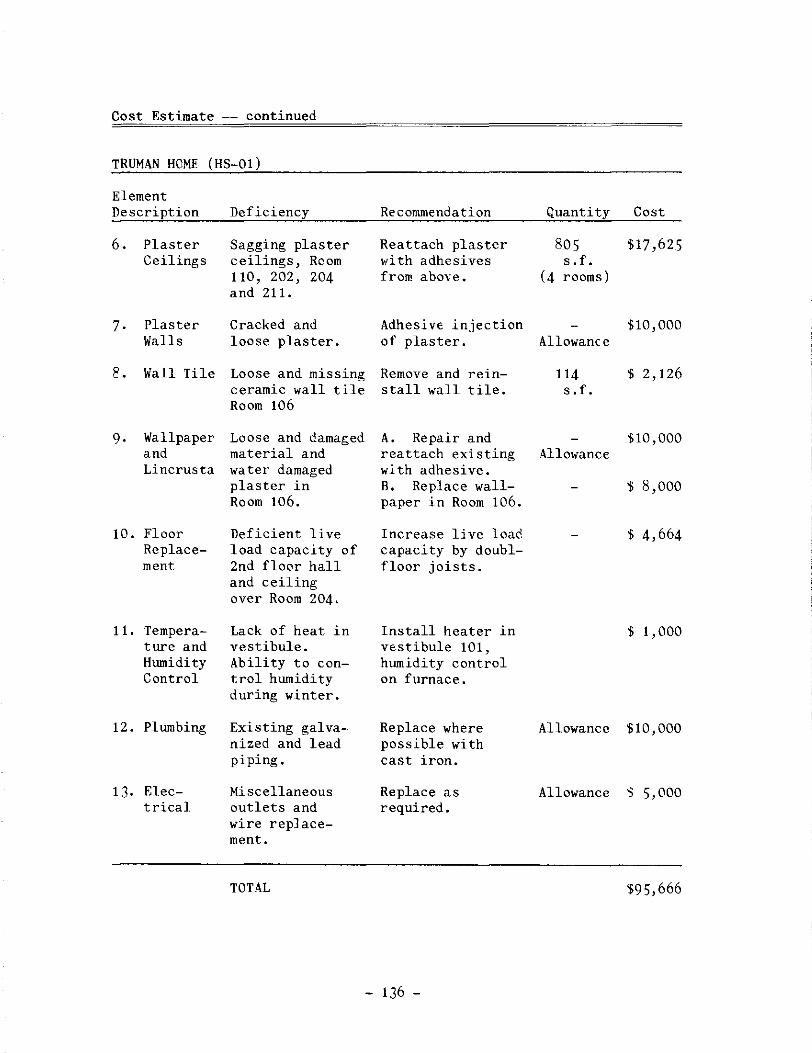
Cost Estimate -- continued
TRUMAN HOME (HS-01)
Element Description
6.
7.
E.
9.
Plaster Ceilings
Plaster Walls
Wall Tile
Wallpaper and Lincrusta
10. Floor Replacement
11. Temperature and Humidity Control
12. Plumbing
13. Electrical
Deficiency
Sagging plaster ceilings, Rcom 110, 202, 204 and 211.
Cracked and loose plaster.
Loose and missing ceramic wall tile Room 106
Loose and damaged material and water damaged plaster in Room 106.
Deficient live load capacity of 2nd floor hall and ceiling over Room 204.
Lack of heat in vestibule. Ability to control humidity during winter.
Existing galvanized and lead piping.
Miscellaneous outlets and wire replacement.
TOTAL
Recommendation
Reattach plaster with adhesives from above.
Adhesive injection of plaster.
Remove and reins tall wall tile.
A. Repair and reattach existing with adhesive. B. Replace wallpaper in Room 106.
Increase live load capacity by doublfloor joists.
Install heater in vestibule 101, humidity control on furnace.
Replace where possible with cast iron.
Replace as required.
- 136 -
Quantity
sos s .f.
(4 rooms)
Allowance
114 s .f.
Allowance
Cost
$17,625
$10,000
$ 2,126
$10' 000
$ 8,000
$ 4,664
$ 1, 000
Allowance $10,000
Allowance $ S,000
$95,666

IV. Design Development and Recommendations
B. TRUMAN CARRIAGE HOUSE (HS-02)
Introduction
Due to the structural configuration of this facility and the deter
mination that the existing structural members are showing only minor
above grade deterioration from various causes, it is the opinion that
the Carriage hovse is not in any immediate danger with respect to normal
day-in, day-out loading a.pplications. However, there are several areas
or items which could receive some immediate attention and add a sub-
stantial safety factor against possible damages which could be incurred
by the failure of this structure and subsequent damage to the materials
stored within. 9
Recommendations for Restoration
Outlined below are recommendations for treatment of the Carriage house.
Topography
A swale along the south elevation should be installed so that water
flows away from the face of the structure, eliminating direct contact of
the wooc siding with the soil. Likewise, the site of the east and west
elevations should be regraded to promote positive drainage away from the
face of the structure. There should be a termite examination on a
regular basis.
- 137 -
l

Vegetation
Leaves that have accumulated in the interior of the Carriage house
should be removed. Shrubbery facing the west elevation of the structure
should be trimmed back from the face of the building to prevent wet
leaves from resting against the siding and to promote drying of the
lower portion of the building and adjacent ground after rainfall.
Foundation and Structural Posts
The foundation of the Carriage house is in an extreme state of decay.
Action must soon be taken to abate the progressive rate of settlement
and the causes of deterioration before additional structural and
cosmetic problems develop. Although an aggressive, overall restoration
is not planned before the fiscal year 1987, it is recommended that
repairs be made to the foundation and primary structural posts.
It is recommended that a partial concrete sill be slipped beneath each
structural post in place of a wooden sill. In this way, the problem of
sill decay would net occur. Siding could be fastened to a treated 2 x 4
anchored to the finished surface of the interior concrete slab. Post
bases should be repaired using structural epoxy and fiberglass rods. In
order to complete these repairs, siding will have to be temporarily
removed and shallow holes excavated at each post. Portions of the
concrete slab would have to be removed around posts 3, 4, 5 and 20 only
to expose the base. The foundation wall should be stabilized at the
bearing point of each reconstructed post base. Salvaged siding and trim
- 138 -
should be fastened back into place as existed. 10
It is also recommended that the cracked concrete apron along the north
elevation be replaced and expansion joints installed where the apron
abuts the garage floor and driveway.
Wall System Framing
Assuming the hidden ccnnections in the structure are similar to those
visible, the garage has little ability to resist lateral forces such as
those experienced during wind loading and to some extent the horizontal
reaction produced by the gravity force and the eastward lean. It would
be highly beneficial to install X-bracing to the vertical members, both
in the garage and loft areas. In the upper area these should be 12
gauge by 3 inch wide metal bands attached to the existing columns using
bent 1/8 inch steel plates secured to the column by four 1/2 inch
diameter screw lags. In the lower garage area the connections would be
similar to the above but a 12 gauge by 4 inch wide metal brace should be
used. These braces should be installed on the perimeter columns of the
east, south and west walls. The diagonal X-bracings would also minimize
any further leaning of the structure to the east. 11
Roof Systems
It is recommended to securely fasten the downspout (located at the north
elevation) into the elbow. In addition, it is recommended to replace a
6 foot horizontal section with a 10 foot long section, and to install a
- 139 -

splashblock to minimize erosion where water empties onto the ground.
The roof is approaching the end of its life expectancy and should be
replaced. New shingles and flashing should be installed, and shingles
should be stained green. Replacements should match existing materials.
To assure that the new shingles can adequately breathe and new flashing
is properly seated, it is essential to remove existing wood shingles,
valley and hip flashing.
A new gutter, downspout and splashback should be installed at the south
elevation to remedy poor drainage. However, if a gutter and downspout
were not extant during the Truman era, and maintaining a gutterless
appearance is paramount, a French drain could be installed along the
south wall to mitigate the impact of rainwater falJing directly to the
ground below the cove.
Floor/Ceiling Structural Systems
It is recommended to install vertical support in the loft to support the
lower ends of the existing valley rafters on the north and south sides.
Loading of loft floors should be limited. 12
Building Envelope
Replace missing board, east side of cupola, or install lexan.
Replace all split battens with new wood to match existing. If replace-
- 140 -

ment is necessary where plain square battens occur, replace with in
kind.
Replace two lower window sills on the east elevation and set so that
sills slope outward. If maintaining material integrity is critical,
sills could be repaired with epoxy filler, epoxy consolidated where
required, and repositioned to slope outward. Consolidate the bottom
rail and lower portions of the stiles on the two lower windows.
Install a metal drip at top of the low windows and doors on the east
elevation and above the loft doors on the south elevation. Ccnsolidate
the lower ends of the boards on the loft doors and replace the missing
board.
Refasten the loose boards on the north side of the door at the east
elevation.
Replace the rr:issing cove molding at the pediment of the north window on
the west elevation.
Cover holes in board anc' batten for previous electric service with clear
polycarbonate glazings screwed into interior face of siding.
Consolidate decayed lower ends of wood siding.
- 141 -
Exterior/Interior Finishes
Strip paint from siding, trim, eaves, soffits, windows and shutters.
Caulk gaps in siding. Prime and paint using historically accurate
colors (See Appendix A, Marie Carden, Paint Analysis). Exterior and
interior paint chromochronolgy should be done to verify colors,
particularly on shutters.
Security System
Consideration should be given to locating an ad.ditional manual fire
pull.
Recommendations for Further Research
Exterior and interior paint chromochronology.
- 1'42 -

Introduction to Cost Estimate
Since the restoration work required for this project is specialized and
often unfamiliar to craftsmen, the cost estimates should be utilized as
a guide to establish work priorities and general cost range. The
following include General Contractor's overhead and profit as well as
that of the subcontractor's. The estimates are based on June 1, 1986
costs. Inflation factors should be applied aE appropriate when the work
is contemplated.
Cost Estimate
CARRIAGE HOUSE (HS-02)
Element Descriptior, Deficiency Recommendation Quantity Cost
1. Grading/ Grade in ccntact Regrade to below $ 4,575 Sitework with wood, nega- wcod and for
tive drainage, positive drain-vegetation in age, replace contact. vegetation, 6
bushes, and resod.
2. Founda- Wood sill and Consolidate in 20 Pests/ $ 5,000 ti on/ structure posts place with 114 ft. NFS Structure rotted. concrete and Sill Labor Posts epoxy.
3. X-Bracing Lack of lateral Install metal $ 3,500 stability. bands to stabi-
lize wood frame.
4. Roofin€;/ Wood shingles Replace with new 1,150 $11,000 Flashing and metal flash- wood shingles s. f.
ing deteriorated. dipped in green stain, and metal flashing, gutters and downspouts.
- 143 -
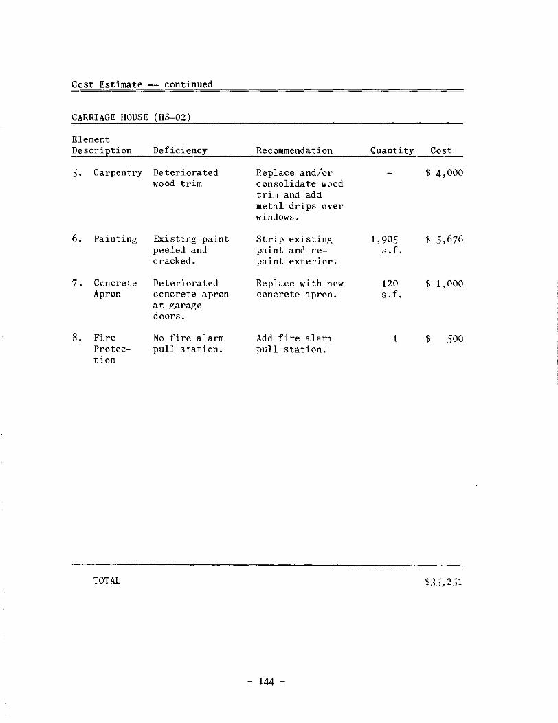
Cost Estimate -- continued
CARRIAGE HOUSE (HS-02)
Elemer.t Description Deficiency Recommendation Quantity Cost
5. Carpentry Deteriorated Replace and/or $ 4,000 wood trim consolidate wood
trim and add metal drips over windows.
6. Painting Existing paint Strip existing 1,905 $ 5,676 peeled and paint arn'. re- s. f. cracked. paint exterior.
7. Cc·ncrete Deteriorated Replace with new 120 $ 1,000 Apron ccncrete apron concrete apron. s. f.
at garage doors.
8. Fire No fire alarm Add fire alarn 1 $ 500 Protec- pull station. pull station. tion
TOTAL $35,251
- 144 -
Notes to Chapter IV
1. Restoration Associates, a division of Solomon Claybaugh Young Architects, Inc., "Analysis of Condition Report HS-1 Truman Home, Truman Home National Historic Site" (Kansas City, February 14, 1985, bound copy) , 4. 5.
2. M. A. Panethiere, "Electrical Rerort, Harry S Truman House" (Kansas City: Associated Engineering Ccnsultants, March 31, 1986, photocopy), 2-3.
3. United States Department of Interior. "Alternative to the StairTrac for the handicapped access of Harry S Truman Nationa.l Historic Site" (National Park Service, Orr:aha, Necraska, May 29, 1986 photocopy) 1.
4. Ibid.
5. United States Department of Interior. "Handicap Access Survey of Harry S Truman National Historic Site" (National Park Service, Denver, Colorado, March 22, 1985 photocopy) 5-7.
6. Ibid., 7-9.
7. Ibid., 5-8.
8. Michael Lee and Alan O'Bright, "Physical Investigation Report Truma.n Home (HS-01) Harry S Trurr.an National Historic Site" (United States Department of the Interior, National Park Service Midwest Region, Orr.aha, Nebraska, July 24-26, 1984, photocopy), 4.
9. Lawrence S. Graham, P.E., (Kansas City, Harper and Kerr July 26, 1985, photocopy), 4.
"Truman Garage, Independence, Missouri" Consulting Structural Engineers, P.A., Hereafter cites as "Harper and Kerr."
10. National Park Service, "Physical Investigation Report and Treatment Propc·sal, Truman Carriage House (HS-02) Foundation, Harry S Truman National Historic Site, Independence, Missc.uri" (Omaha, Cultural Resources Managerr.ent Division, 1985, photocopy), 4.
11. Harper and Kerr, July 26, 1985., 4.
12. Ibid., 5.
- 145 -
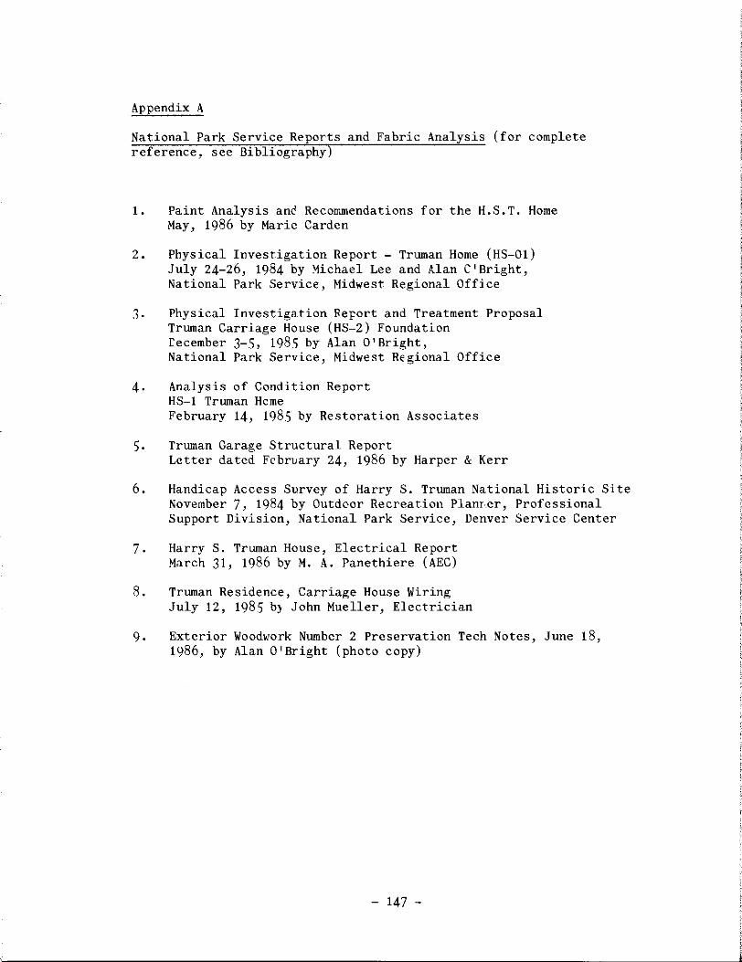
Appendix A
National Park Service Reports and Fabric Analysis (for complete reference, see Bibliography)
1. Paint Analysis anc Recommendations for the H.S.T. Home May, 1986 by Marie Carden
2. Physical Investigation Report - Truman Home (HS-01) July 24-26, 1984 by Michael Lee and Alan C'Bright, National Park Service, Midwest Regional Office
3. Physical Investigation Report and Treatment Proposal Truman Carriage House (HS-2) Foundation recember 3-5, 1985 by Alan O'Bright, National Park Service, Midwest Regional Office
4. Analysis of Condition Report HS-1 Truman Heme February 14, 1985 by Restoration Associates
5. Truman Garage Structural Report Letter dated February 24, 1986 by Harper & Kerr
6. Handicap Access Survey of Harry S. Truman National Historic Site November 7, 1984 by Outdoor Recreation Planr,er, Professional Support Division, National Park Service, Denver Service Center
7. Harry S. Truman House, Electrical Report March 31, 1986 by M. A. Panethiere (AEC)
8. Truman Residence, Carriage House Wiring July 12, 1985 by John Mueller, Electrician
9. Exterior Woodwork Number 2 Preservation Tech Notes, June 18, 1986, by Alan O'Bright (photo copy)
- 147 -

Appendix B
Chrorological List of Work Completed by the National Park Service
1. CX6000-4-0020, $44,900.00. Roof Repair, March-April 1984.
2.
Penn Perry Inc., Wexford, PA. Repair/replacement of flat seam metal roofing, built-in gutters and downspouts.
CX6000-4-0028, $12,655.00. home, Dec. 1983-April 1984. MO.
Rehabilitate Electrical System, Truma.n Watkins Electric Co., Independence,
3. CX6000-4-0062, $3,900.00. Sidewalk Repair, April 1984. Hamilton Concrete Construction, Indeperdence, MC:. Partial replacement of sidewalk inside of fence.
4. PXll00-4-115, 7, 716.07. Visitor use carpet, April 1984. Robert T. Baker, Kansas City, Missouri. Historic wall-to-wall carpeting was removed from spaces 102, 103, 107, and 110. Historic carpet was mcved to storage at Truman Library. New natural and grey colored nylon carpet from the floorcoverings division of Dan River Inc. was installed in the spaces listed above as well as a platform into space 109, a runner through 111 and 113. Grey indoor-outdoor carpet was installed on back porch (space 114E). The above purchase order was amendec later in April for an additional $1,113.21. Modifications to grey visitor path were made by PX 6460-4-0079, $180.00 in September, 1984 and PX 6460-5-0051, $135.00 in September, 1985.
5. PX6460-5-0030, $1,258.82. Plumbing, April 1985. Evans Plumbing & Heating, Independence, MO. Replaced existing water pipes in Truman home basement using type K hard drawn copper pipe; replaced inground hydrant near water meter; and repaired leaking 4" lead drain pipe.
6. PX6460-5-0018, $352.62. Hot Water Heater, May 1985. Evans Plumbing & Heating, Independence, MO. Installed Dayton 6 gallon, electric, 120 volt, 15 7/8 11 H x 15" diam. wo"ter heater; cabinet with double bowl stainless steel sink and faucet w/spray in basement of Truman home; and drained existing 40 ga.l. water heater bLt did not disconnect it.
7. PX6460-5-0033, $1, 180.00. Rewire Carriage hcuEe, June--July 1985. MDG Company, John Mueller owner, Independence, MO. Rewired Carriage house; disconnected existing aerial electrical service at the power pole; disconnected existing aerial branch circuits; installed underground conduit, 2-1/2" inside diameter PVC; galvanized electrical metal tubing; copper wire w/insulation rating of 600
- 149 -
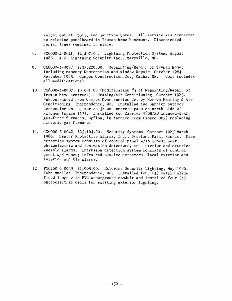
volts; outlet, pull, and junction boxes. All service •as ccnnected to existing panelboard in Truman home basement. Disconrected aerial lines remained in place.
8. PX6000-4-0641, $4,497.09. Lightning Protection System, August 1985. A.C. Lightning Security Inc., Maryville, MO.
9. CX6000-4-0097, $233,220.00. Repainting/Repair of Truman home, Including Masonry Restoration and Window Repair, October 1984-November 1985. Campos Ccnstruction Co., Omaha, NE. (Cost includes all modifications)
10. CX6000-4-0097, $9,031.00 (Modification #5 of Repainting/Repair of Truman heme contract). Heating/Air Conditioning, October 1985. Subcontracted from Campos Cc•nstruction Cc•. by Morton Heating & Air Conditioning, Independence, MO. Installed two Carrier outdoor condensing units, series 38 on concrete pads on north side of kitchen (space 113). Installed two Carrier S8DH/SS induced-draft gas-fired furnaces, upflow, in furnace rcom (space 003) replacing historic gas furnace.
11. CX6000-.5-0042, $2.5, 164. 00. Security Systems, October 198.S-March 1986. Sentry Protective Alarms, Inc., 0Yerland Park, Kansas. Fire detection system consists of control panel w/16 zones; hE,at, photoelectric and ionization detectors, and interior and exterior audible alarms. Intrusion detection system consists of control panel w/8 zones; infra-red passive detectors; local exterior and interior audible alarms.
12. PX6460-6-0039, $1,96.S.OO. Exterior Security Lighting, May 1986. John Mueller, Independence, MC. Installed four (4) metal halide flood lamps with PVC underground conduit and installed four (4) photoelectric cells for existing exterior lighting.
- 1.50 -

Appendix C
Anticipated Work by the National Park Service
1. Reroof Truman Home
Material - Match existing aephalt shingles. (NOTE: Historic shingles were installed in 1969. The shingles were discontinued by GAF in 1984. No shingle manufacturer currently makes two-tab shingles. A minimum of 1,000 squares is required for a GAF custom order. The Truman home require~ about 34 squares of asphalt shingles.
Cost Two-tab shingles $50,000 - $100,000 Three-tab shingles - $15,000 Slate shingles - $60,000
Date - Possibly in 1988.
2. Repair Rc,tted Posts in Carriage House ( HS-02)
Material - Epoxy consolidation as per "Physical Investigation Report and Treatment Proposal, Truman Carriage House (HS-2) Foundation" dated December 1985.
Cost - Work performed by National Park Service staff (Alan O'Bright and Michael Lee). Materials cost estim<.ted at $5, 000.
Date - Fall, 1986.
3. Paint Steel Picket Fence
Material - Repaint to match existing.
Cost $14, 000
Date - Fall, 1986.
- 151 -
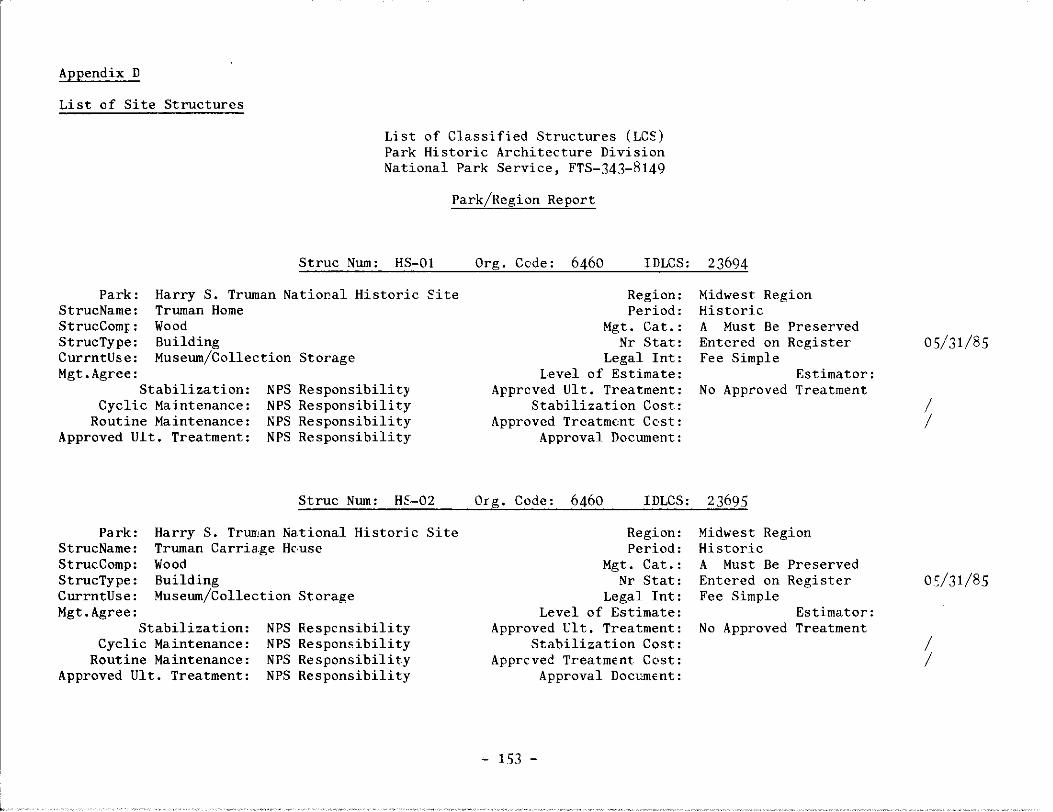
Appendix D
List of Site Structures
List of Classified Structures (LCS) Park Historic Architecture Division National Park Service, FTS-343-8149
Park/Region Report
Struc Num: HS-01 Org. Code: 6460 IDLCS: 2 3694
Park: StrucName: StrucComp: StrucType: CurrntUse: Hgt.Agree:
Harry S. Truman NatioP.al Historic Site Truman Home Wood Building Museum/Collection Storage
Stabilization: Cyclic Maintenance:
NPS NPS NPS NPS
Responsibility Responsibility Responsibility Responsibility
Routine Maintenance: Approved Ult. Treatment:
Struc Num: HE·-02
Park: StrucName:
Harry S. Truman Truman Carriage Wood
National Historic Site He.use
StrucComp: StrucType: CurrntUse:
Building Museum/Collection Storage
Hgt.Agree: Stabilization:
Cyclic Maintenance: Routine Maintenance:
Approved Ult. Treatment:
NPS NPS NPS NPS
Responsibility Responsibility Responsibility Responsibility
Region: Period:
Mgt. Cat.: Nr Stat:
Legal Int: Level of Estimate:
Approved Ult. Treatment: Stabilization Cost:
Approved Treatment Cc·st: Approval Document:
Midwest Region Historic A Must Be Preserved Entered on Register Fee Simple
Estimator: No Approved Treatment
Org. Code: 6460 IDLCS: 23695
Region: Period:
Mgt. Cat.: Nr Stat:
Legal Int: Level of Estimate:
Approved Ult. Treatment: Stabilization Cost:
Approved Treatment Cc•st: Approval Document:
~ 153 -
Midwest Region Historic A Must Be Preserved Entered on Register Fee Simple
Estimator: No Approved Treatment
05/31/85
I I
os/31/85
I I
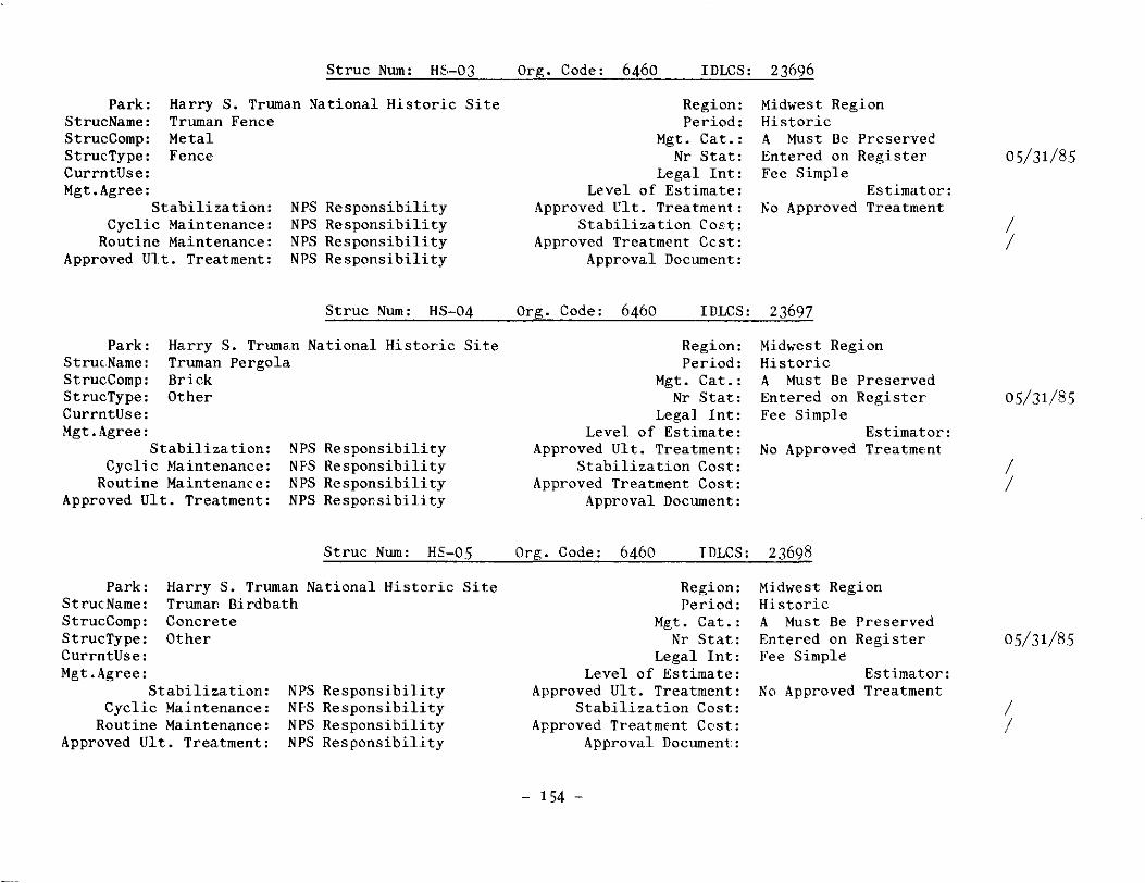
Struc Num: HS-03
Park: StrucName: StrucComp:
Harry S. Truman Truman Fence Metal
National Historic Site
StrucType: Fence CurrntUse: Mgt.Agree:
Stabilization: Cyclic Maintenance:
Routine Maintenance: Approved Ult. Treatment:
NPS NPS NPS NPS
Responsibility Responsibility Responsibility Responsibility
Struc Num: HS-04
Park: StrucName: StrucComp:
Harry S. Truma.n Truman Pergola Brick
National Historic Site
StrucType: Other CurrntUse: Mgt.Agree:
Stabilization: Cyclic Maintenance:
Routine Maintenance: Approved Ult. Treatment:
NPS NI'S NPS NPS
Responsibility Responsibility Responsibility Respor.sibility
Struc Num: HE-05
Park: Harry S. Truman National Historic Site StrucName: Truman Birdbath StrucComp: StrucType: CurrntUse: Mgt.Agree:
Concrete Other
Stabilization: Cyclic Maintenance:
Routine Maintenance: Approved Ult. Treatment:
NPS Responsibility NF·S Responsibility NPS Responsibility NPS Responsibility
Org. Code: 6460 IDLCS: 23696
Region: Period:
Mgt. Cat.: Nr Stat:
Legal Int: Level of Estimate:
Approved Ult. Treatment: Stabilization CoEt:
Approved Treatment Ccst: Approval Document:
Midwest Region Historic A Must Be Preserved Entered on Register Fee Simple
Estimator: No Approved Treatment
Org. Code: 6460 I DLCS: 2 3697
Region: Period:
Mgt. Cat.: Nr Stat:
Legal Int: Level of Estimate:
Approved Ult. Treatment: Stabilization Cost:
Approved Treatment Cost: Approval Document:
Midwest Region Historic A Must Be Preserved Entered on Register Fee Simple
Estimator: No Approved TreatmE,nt
Org. Code: 6460 IDLCS: 23698
Region: Period:
Mgt. Cat.: Nr Stat:
Legal Int: Level of Estimate:
Approved Ult. Treatment: Stabilization Cost:
Approved TreatmEnt Cost: Approval Document:
- 154 -
Midwest Region Historic A Must Be Preserved Entered on Register Fee Simple
Estimator: No Approved Treatment
05/31/85
I I
05/31/85
I I
05/31/85
I I

Struc Num: HE-06 Org. Code: 6460 I DLCS: 2 3699
Park: StrucName: StrucComp:
Harry S. Truman National Historic Site Truman Secret Service Security Booth Site Fabric
StrucType: Other CurrntUse: Mgt.Agree:
Stabilization: Cyclic Maintenance:
Routine Maintenance: Approved Ult. Treatment:
NPS NPS NPS NF·S
Responsibility Responsibility Responsibility Responsibility
Region: Period:
Mgt. Cat.: Nr Stat:
Legal Int: Level of Estimate:
Approved Ult. Treatment: Stabilization Cost:
Approved Treatment Cost: Approval Document:
Midwest Region Historic A Must Be Preserved
Fee Simple Estimator:
No Approved Treatment
Struc Num: HS-07 Org. Code: 6460 IDLCS: 23700
Park: StrucName:
Harry S. Truman National Historic Site Truman Sundial
StrucComp: StrucType: CurrntUse: Mgt.Agree:
Concrete Other
Stabilization: Cyclic Maintenance:
Routine Maintenance: Approved Ult. Treatment:
NPS NPS NPS NPS
Responsibility Responsibility Responsibility Responsibility
Struc Num: HS-08
Park: Harry S. Truman Truman Flagpole Metal
National Historic Site StrucName: StrucComp: StrucType: Other CurrntUse: Mgt.Agree:
Stabilization: Cyclic Maintenance:
Routine Maintenance: Approved Ult. Treatment:
NPS NPS NI'S NPS
Responsibility Responsibility Respcnsibility Responsibility
Region: Period:
Mgt. Cat.: Nr Stat:
Legal Int: Level of Estimate:
Approved Ult. Treatment: Stabilization Cost:
Approved Treatment Cost: Approval Document:
Midwest Region Historic A Must Be Preserved Entered on Register Fee Simple
Estimator: No Approved Treatment
Org. Code: 6460 IDLCS: 23701
Region: Period:
Mgt. Cat.: Nr Stat:
Legal Int: Level of Estimate:
Approved Ult. Treatment: Stabilization Cost:
Approved Treatment Cost: Approval Document:
- 155 -
Midwest Region Historic A Must Be Preserved Entered on Register Fee Simple
Estimator: No Approved Treatment
I I
05/31/85
I I
05/31/85
I I

Struc Nwn: HS-09
Park: Harry S. Trwnan Trwnan Gas Lamp Metal
National Historic Site StrucName: StrucComp: StrucType: Other CurrntUse: Mgt.Agree:
Stabilization: Cyclic Maintenance:
Routine Maintenance: Approved Ult. Treatment:
NPS NPS NPS NPS
Responsibility Responsibility Responsibility Responsibility
Struc Nwn: HS-10
Park: Harry S. Trwnan Trwnan Cistern Brick
National Historic Site StrucName: StrucComp: StrucType: Other CvrrntUse: Mgt.Agree:
Stabilization: Cyclic Maintenance:
Routine Maintenance: Appro>ed Ult. Treatment:
NPS NPS NPS NPS
Responsibility Responsibility Responsibility Responsibility
Struc Nwn: HE-11
Park: StrucName:
Ha,rry S. Trwnan National Historic Site Historical Marker
StrucComp: Metal StrucType: Other CurrntUse: Mgt.Agree:
Stabilization: Cyclic Maintenance:
Routine Maintenance: Approved Ult. Treatment:
NPS NPS NPS NPS
Responsibility Responsibility Responsibility Responsibility
Org. Code: 6460 IDLCS: 23702
Region: Period:
Mgt. Cat.: Nr Stat:
Legal Int: Level of Estimate:
Approved Ult. Treatment: Stabilization Cost:
Approved Treatment Cost: Apprcval Docwnent:
Midwest Region Historic A Must Be Preserved Entered on Register Fee Simple
Estimator: No Approved Treatment
Org. Cc•de: 6460 IDLCS: 23703
Region: Period:
Mgt. Cat.: Nr Stat:
Legal Int: Level of Estimate:
Approved Ult. Treatment: Stabilization Cost:
Approved Treatment Cost: Approval Docwnent:
Midwest Re,gion Historic A Must Be Preserved Entered on Register Fee Simple
Estimator: No Approved Treatment
Org. Code: 6460 IDLCS: 2 3704
Region: Period:
Mgt. Cat.: Nr Stat:
Legal Int: Level of Estimate:
Approved Ult. Treatment: Stabilization Cost:
Approved Treatment Cost: Approval Document:
- 156 -
Midwest R<gion Period
Undetermined NR Status Fee Simple
Estimator: Preservation
05/31/85
I I
05/31/85
I I
I I
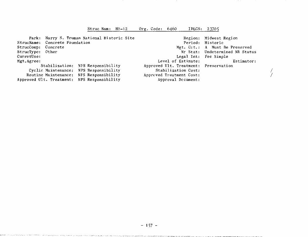
Struc Num: HE-12
Park: StrucName:
Harry S. Truman National Historic Site Concrete Foundation
StrucComp: StrucType: CurrntUse: Mgt.Agree:
Concrete Other
Stabilization: Cyclic Maintenance:
Routine Maintenance: Approved Ult. Treatment:
NF·S NPS NPS NPS
Responsibility Responsibility Responsibility Responsibility
Org. Code: 6460 IDLCS: 23705
Region: Period:
Mgt. C~t.:
Nr Stat: Legal Int:
Level of Estimate: Approved Ult. Treatment:
Stabilization Cost: Apprc·ved Treatment Cost:
Approval Dccument:
- 157 -
Midwest Region Historic A Must Be Preserved Undetermined NE Status Fee Simple
Estimator: Preservation
I I
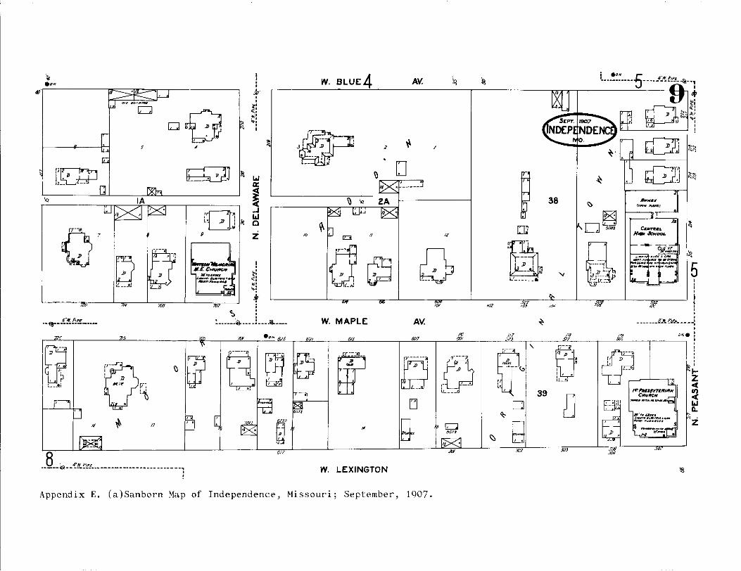
• ...
6-lt_ P1P~ ··'!"----------·-"'
0.,--••
11
. \\\
i;::;J
r/i
L~
n
.. 8 .. ~ -_ {~t'~! •.• ------- ---- - -- - -- - --- - - ... ' !
0 . .. ,
Qd" ~----· J _j
'GJ ' ' L• JJ I .. '
""
~
~
~
I : ' .l> ' , .
..:: ~: •: '
Loi a:
~ ;cc .J Loi 0
z
! t: <t:l ""! •: ~-
'
• •
'.:i : :------~ ___ .1 .... a __ _
··-
W. BLUE:4 AV.
2
W. MAPLE: AV.
0'21 "'
W. LEXINGTON
Appendix E. (a)Sanborn Map of Independence, Missouri; September, 1907.
"' ,,,
= tiO/J
'" .,.
D
38
,,,
'
39
' •.. 5 ·----------- - --- _4}'.. f!!l.~--,
,.
' " ~! :::--,1:::: . ~
'
~
~
5 I I ' I ' ' : .
_______ (i:Jt. !!II'.& -- - -:
(R -, lf'rl'Jtc•fYT~"'""' I CHUl/fCH
-""" ... -··
' IJll.. ~
' ' i . ' ' .... z <(
:l loJ D..
~z

17 W. VAN HORN <,f{
' 4 :· . (] ~:
rj ~
••• . ' 6 ~
~ "
[~ 0 . .
_,, ' .. .
,, ___ --__ .: ~ " ~7. '--~~~-L,,~~~~--,,w,--L~~-,,,,-~~-L~~~-,,,~,.--~~~.i_---..--~.!____::.::,;:;~~~
, . ~
•..
" ~
,_p .ill
W. MAPLE AV.
W. LEXINGTON
Appendix E. (b)Sanborn Map of Independence, Missouri; August, 1916.
1-z ~ ~ ..J 0.
i.
~
~
1--~~=r-~:J.=~~~--"='~~-----,1 J2 ~ ,iJ
Qff ~1
~ . ,_J _____ jJ
,. "" "'
,,,
~ ~ Q ~ . . . . "' g Jo (I~) E.( v
'(JJ ~ Q ;,; I i,c __ ,j ____ .,
•!·---~' • u
.,r~'r '~w: ,_ ..•
~.
,.
~ Q/,, •
fil ,,,
17
" z
°' 0. Ill
i.
~

~: ,, ,. ~:
~
j~, ~ .;1
J ... a: <(
~ <( " ..J
"" 0
z
' ' :::: <>.: .~:
': <:'' •
' . - -- - __ :.._ ___ ~-- _f:"! f''.P_~.
] o: nm ~----' __ •...: ·~---·...: ,!_ __ ~,
,. 5~
27 '" €0.'
''°
,,, _L
0 . ··-~
5<0 -----~=-
W. MAPLE AV.
tz <( '1l <( .... ..J a.
-··-~---
.51.5 ___ .<1~ __ 5'm._25e'!;;'_;-5,,,·~ .. ,__,.5''l_'-------\~----~·P·~ ~ ,,
,---. ~~' -~ ·u f---.,-,
/~T PRES l'1f CNUFICH
. .cl.,,. i;,;J ()
88~~ W. LEXI NG TON AV.<"l
Appendix E. (c)Sanborn Map of Independence, Missouri; August, 1926.
(18115!
, '
:·e' I" ~acn~<q •
'
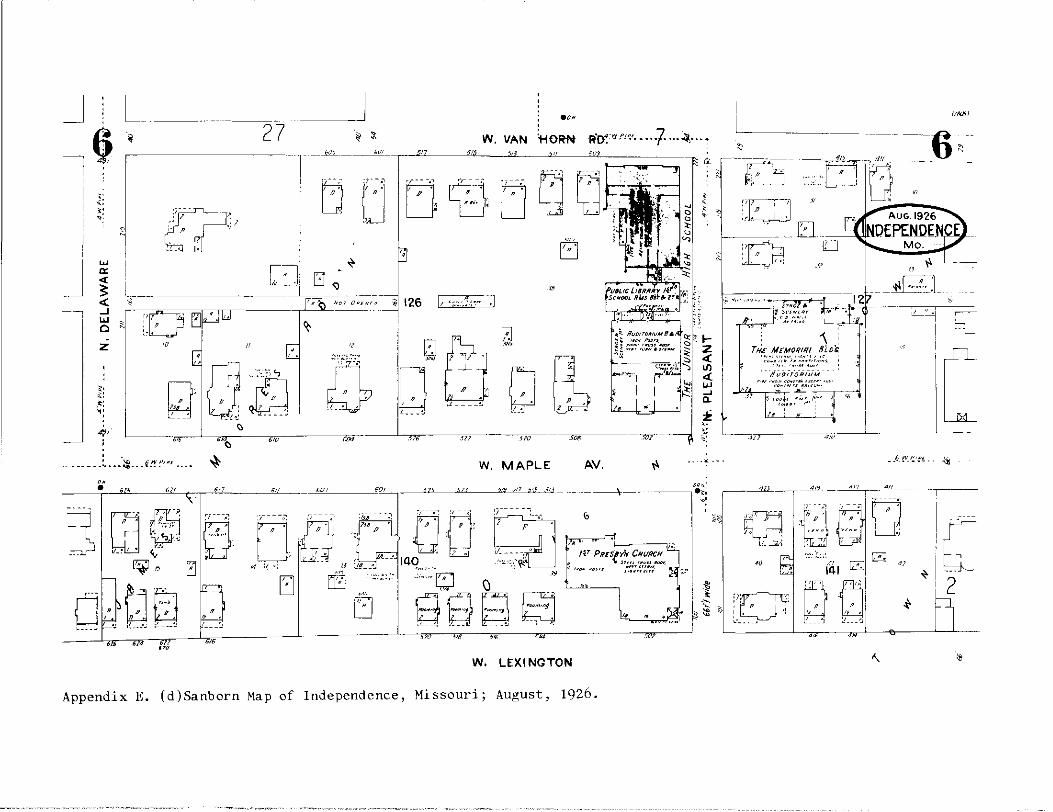
J L __ _ _J -~ 27
-- ·1- __ _s_11_1_ ___ _______i!!!__T~~-~""'----""'-' _ ___i'L___.£<'"~=:::::;;;:=:=,;,-1" ~
z •O . . .
tJ[j[J,g
RO~ l} ' -
·~·-----:..- .. ~ ___ {!~:"'"'. W. MAPLE
• 61-'
W. LEXINGTON
AV.
-- ------\.- -
Appendix E. (d)Sanborn Map of Independence, Missouri; August, 1926.
.;;:: . -
(i/lll'il
" II
- '111 ··-~·J_ -~
~
•. ILL
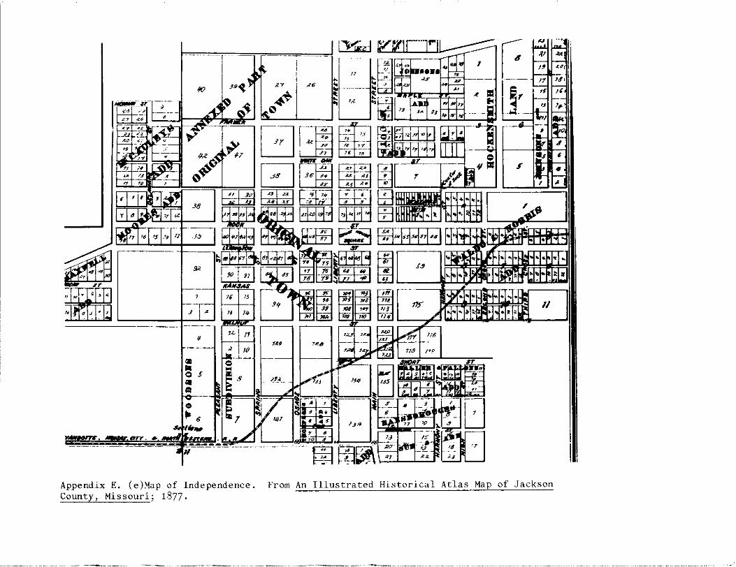
. ·---1
ii(} 39~
j I' " -------·
1Z I
" 10
-'-e ... s 6 '~ r -ie,
Appendix E. (e)Map of Independence. County, Missouri; 1877.
""' ~' ... ,,
" ~ 11 n ~6 .. ~~
.. '~
'"'
,,. :-~a
/1_(>
;_J_~--
••
' • >o , .,
·~
From An Illustrated Historical Atlas Map of Jackson

.,, ti.-- •
---B-L U- E- - ----~
J. ll.>'•rliis :1.1.'f11.
-I.Ill,, .
~ 2 ~ ff. f; • JI. f!#I/ II
! REE ~E'S
r I • ~ i
I !
.. ~ '--u;;~=;r==;;;n;: <:I r.. liq
...;
.IU...IUll/ .._...,.._
a
th WOODLAND COLLESE
-~:I 40 I .
0 9
8
i i
L. ~ --~-- -··----· --- --···-·--· --.-,· .. -:-- . 1' J.B. >'•rlis~
I 9' :/. g : '~} ,J - ! I' I :..J J ' - -~ . "- ,."{ ~)), il. :.Ht · ,,.,.,.,., . "" .1 · J.1 •. r-.,r .. 1• . . . . ,\' g ; ... ~ . ,, ~,.. ..i1Z:-.
. , ;:I
---.. · -~ IFA ~ : ,.,,_. 7.1.-:-· ...... ,,
__ --;C-r c::, ,- -- -a . -- ,CJ i- -J -- ' . - T • ~ • ~~~ .-,;.:;-·10-·...: ,.... ... ~. - - D , "' . \.I" "' .•.• ,_,..,.._ .....
_..----~. lu" ' Joi _ ... I I - I
,~-:;:- __,!ilJ I : --i~ • ' Q ~: ~ .(
- ·1 - I I - .! \•, ,, r --- u ...., -;'.~r i --~· . ! 1lt. i• , ,,..: . -)>t: J, K T«tX:
. ....... ..... i :.J
n~~~O- a f[a:~ ~: -_ 1•~ fc K I I I ! : •' i ; __ ~--J;.t f;·
~-
,\'Ur f:el ~f."'-foi -i-l:i _ E' 1liLi _ l I aP 1Cbi,,_.~JI1 .. ..,,,.-:,-..,.-.,,,,---,--,-:::---J---=::!1,. ~J
.-.~.r w WALNUT
~ -;;~r--.-.- -~ r- -- --- -- ----- --! '
Appendix E. (f)Map of Independence. From Atlas of the Environs of Kansas City in Jackson County, Missouri; 1886.
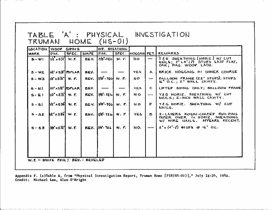
TABL~ TRUMAl\J
'A' : Pl-IYSICAL 1-tOM(;. (~S-01)
L0'11.TIOll WOOV SIPIN G WV. SHl<ATHll-IC.
SllA.rE. p IM. sri;:c . IJO<.GllJ~ I'&: T.
s-w1 ISC: V. 1/a"-1·(c. w. f'. ho - Ir~ er. .:.1.1~.r.. Trn~tc. ( 1-10"1z. .) w/ c.uT NAIL!ii.; Z' • -1" { i') ::)TUl'S Lf\111 FL.t\T, OAK; Plf\6. WOOV Ll>-T~-
.3 - W Z. 1/z' "'5)1.' l't>rLll.K 5E.V.
:s - W3 •/L"xs~· w. I'". l!.(;V, 7/&0 -T~<, W. r.
"-.1.u s - i;;. 1 1/z". sYz." w. r. ISC:V. 7/6"- T4 u 'N. I".
:!> - s 1. l/z" x5~ w. r. e,i;. v. 7/&" -nc. w. r.
s. - .s z ia• x s¥i w. r.
S-53 l!>C:V. 7/9"· T4 f. W. I".
w. r. ::. w111ri;: run:.;· isc;:.v. - ar::vi;;:LI0.17
A I!."' IC.K NO(,,G.IN<.. It I 5111N!;."' c.ou"'si;;.
c
f',/\LLOC>f.l F"'"MC: (ZZ.' ::.TUV~; !>TUVS fl." 0.C..; z.• Wll.LL C1'VITY.
LIFTl<.17 SIVING. ONL '(; ISJl.LLOOIJ FMMI:
NO - T~G HOKIZ. :SHGf\TlllN6 W/ C.UT NAIL5; Z.- INC'..ll Wf\.LL C.f\.'llTY.
"'o p .,. i!. G. 11or:.1z.. s-11;;,...nm1c, w/ cur N"I LS.
vi;.s 15 :Z-LA.Yk.KS f<.OSll.J-(.Of\.Tl<'.V l!>UILVllH. rAri;;.K O'IE'.K '"' llO"'IZ. srn;:1>..nflt.16 w/ Wll"E 1~1'1LS. .-.rri;;A.~S "'t;;C.!;;:NT.
"'o. :Z">< (4'-i') 6TUl'!o @ I(," O.C..
Appendix F. (a)Table A, from "Physical Investigation Report, Truman Home [PlR(llS-01 l I," July 24-26, 19R4. Credit: Michael Leo, Alan O'llright

; \ :J-+-----' _,. I./ " ,, • ·.__ iC31z·_--_sTvl7.s, 14~5-_o.c..
(BACK"G~OU~ 17)
~ -A:f.:--1-------1'517 f>F..IC.K (z. Y-1'" -4« 8"LLA1 V' It>.! !.A.}..;17 ~ L.IM;:. MOF..7Ai\., -S~11.J~1' C.OUF..S;:.
sec.
1°'R'OK, f:tc:=rnr~isoA.PCVS. l':;;.li'"- ~IC~-S;.fll>J~ e.:>u~:.,
::S:LU17 -(ls~N17)
f."'-;.;.J.---- WOOV' L.>-TM ! F'l-"51";::.Ft
AlfC U..VITY
~1...~=~· ... 11-o'e)WALL .Sb:.C.. 17£TA!L
Appendix F. (b)Wall Section Details. PIR(HS-01).
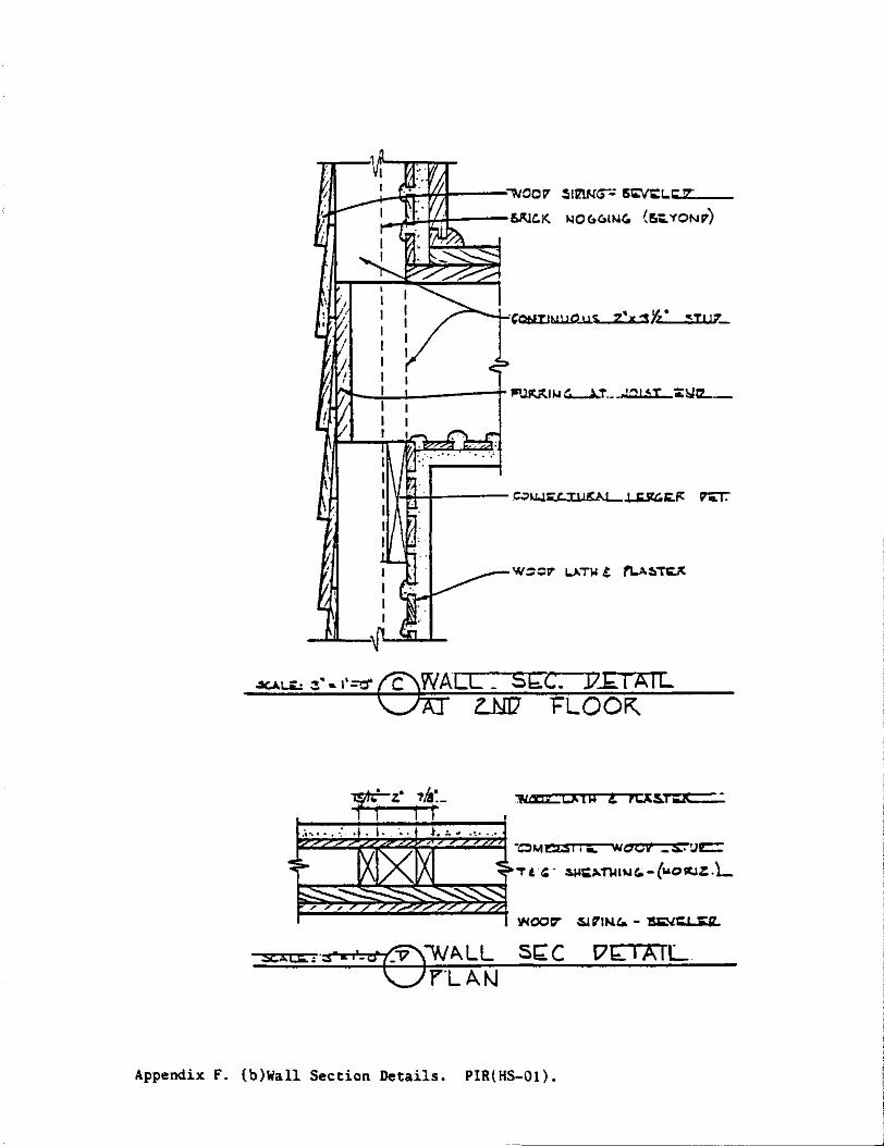
I
' '
SIM<;-.: 5~1..c;-.:<.IZ"-
:___.u~.,:i.----~C.K MOC.C.IM('. (!'.;::<ONV)
~c:xcu a: rcx~r;:c::::,:
~~Z:::::!;2::~22~~~·::,t•:::·t••Z:··~· •Qa,,tt:LSI 1 .._ WO'Cif' _£.!JC::
~,~, ~~ "Tt '· ~i;,,.nm.u.-(wcn~.1z.L
St;;: C C7b:IAIL
Appendix F. {b)Wall Section Details. PIR(HS-01).
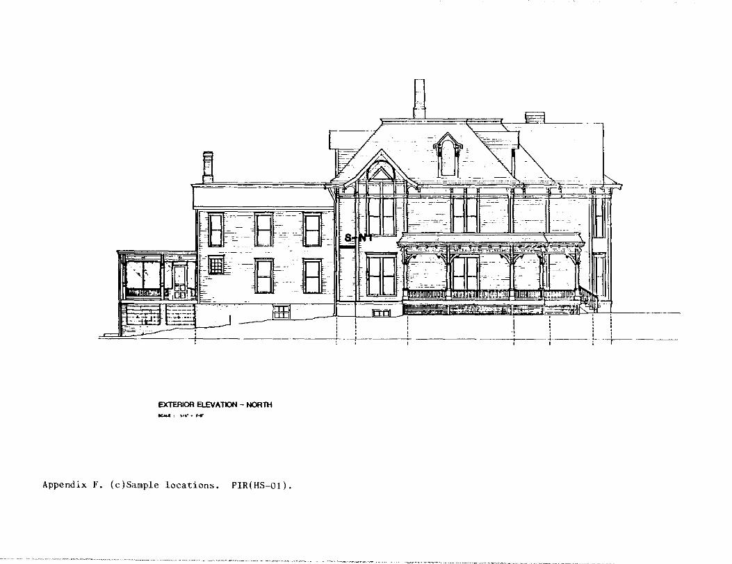
EXTERIOR EL£V A TION - NORTH
Appendix F. (c)Sample locations. PIR(HS-01).
··m, -- _-
' I '
1)-
-
-~-----~
' '
: I ------/------ - -------
' ' -~---·----
' ' '
' i ' : : . t- --+- ---·---

.~---
-----·---·-<---- ---- _ __, __ -~--+- ----+-- -+--- --<----· --·--
EXTERIOR ELEV A TION - WEST
Appendix F. (c)Sample locations. PIR(HS-01).
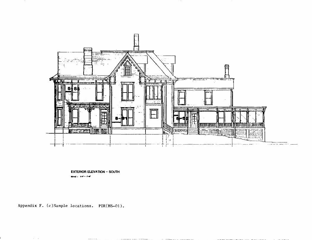
-~---------- -~ - -=-~--"'--~----~-=---=-~--=------
9...,IA"llHI
~i ~fil_~----------+-------- --'
' ' ' : : -+--+ -- ------------.-+---------~-1 l
t------ ------------- -
EXTERIOR ELEV A TION - SOUTH KAI.&' 114•. , ....
Appendix F. (c)Sample locations. PIR(HS-01).
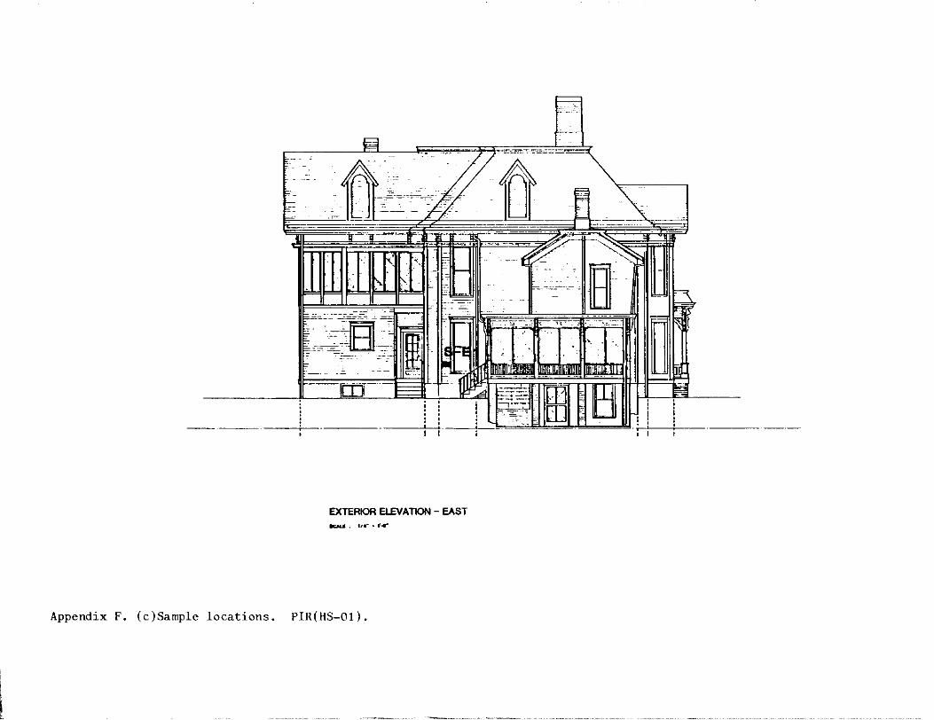
Q -=-=~= ~- . -- -
~- - ---;:-.,.;;-_-_ . ----- ~Jr=if ~ - - -=-- D-:::-
7 -- --- - - -
[I]I
-----·-
EXTERIOR El£V A T10N - EAST
Appendix F. (c)Sample locations. PIR(HS-01).

CARRIAGE HOUSE (HS-2) HARRY S TRUMAN NHS
POST BASE CONOITlON SCHEDULE
(/) BEARING CONDITION
z Q (/)
...I (/) ~ z 0 a: >CC < w w a: :::E 0 g; 0 a:O I- I-< 0 0 < 0 WO w 0 :::E Cl u. a. >a. 0 z
I (;-x (, • ~.~ 2. ~x/P • KFaN'm ~ 5112.lr '5 31~ • W;e., rz.or 4- ~)<~ ttli • ~p.or
5 5 lf2.l< '?~I+ • l'\~0-. ~ (p ., 1/2.)C '5 ?/4 • 5 N?i?.M" 1 q x~ 1-\H • ? ~.Pot" e; ~lfz.Jc e>vz HH • 4- ~.Ft/T,T
0 4x4 NE .. 10 ~llz.xfiltz. Hti • ~. !?Ur,T I I 2x ~ te IZ e> llz.it ~l{z.Ht\ • 2,; ~.IZOr I~ 71/u 15;1+ • 3 ~.!ZOt"
14 5"2.~ 7J14 • ~.fZOT
I? 5 "2.. )f 5 !/4 • I rzot",T I l- 4ic4 t'e:.. \1 i:i llz. ); is ~ '"" • I ~.~
I eo s llz..lC '5 ~/4 • I ~.~
'C) 4x4 ~ z.o ~ ll °> 1-1-tt • N";e(~) ' l'01"
1-SE.X
Appendix C. (a)Post Base Condition Schedule, from "Physical Investigation Report & Treatment Proposal, Truman Carriage House [ PIR(HS-02)]," April, 1986. Credit: National Park Service, Midwest Region.
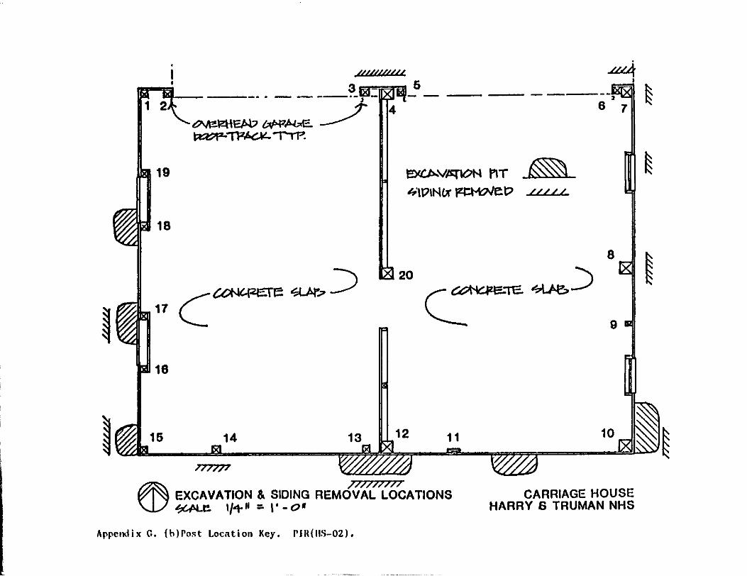
19
18
16
3=-=n 6 '-- ----·. - - ---·-, - - - --- ---
~\ZHEJ>.V W>f!,A.c.E.. __/ ~~"TTP.
14
/)//}}
4
~V,lltflON l'IT ~ .fi\DINIX ~D ///I/
12
--. 6 7
8
9
10
~EXCAVATION & SIDING REMdfAlt'{bcATIONS W ~e 1/+H =-I' -o•
CARRIAGE HOUSE HARRY 6 TRUMAN NHS
Appendix G. ( h) Post Locnt ion Key. I' lit ( llS-02).
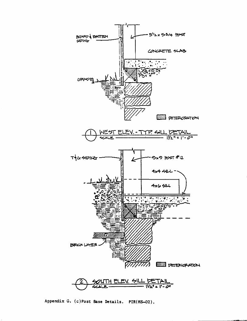
C9
Appendix G. (c)Post Base Details. PIR(HS-02).

If..___--_lL
Appendix G. (c)Post Base Details. PIR(HS-02).
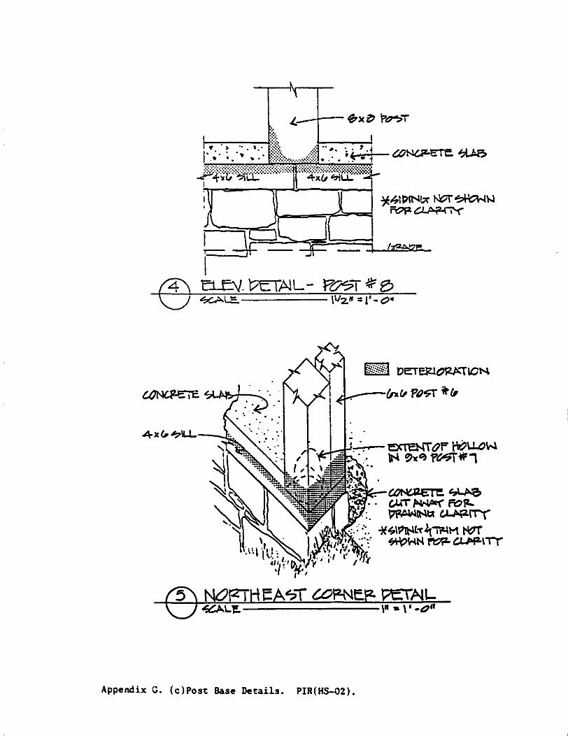
~41PINlA ~~\..I 1\--=--=~:!=o-..-:I FO!Z c1 "? l""i'{'"
,J /
_\ - =4:l..._...I........ _J( l ·~ I .JI
F1 BJ. 'VET~L- f707T ~ B
lifZ'if.{i,j OETElZ.IO'iZJ>.'"TICN
.1 ~--(p.r, P'1-s=f ft(I
Appendix C. (c)Post Base Details. PIR(HS-02).

12€M?Ye.. Ft>STTO ~ND~.
-
.. . . . . . ~.i ': 1· ~--·+ .. + .. . 1-eW ~ i?>~ • •• •
F'O?T ~rz.~L-""T'(P.~Tt~N ~~ 1ifi•.,. I' -o•
Appendix G. (c)Post Base Details. PIR(HS-02).
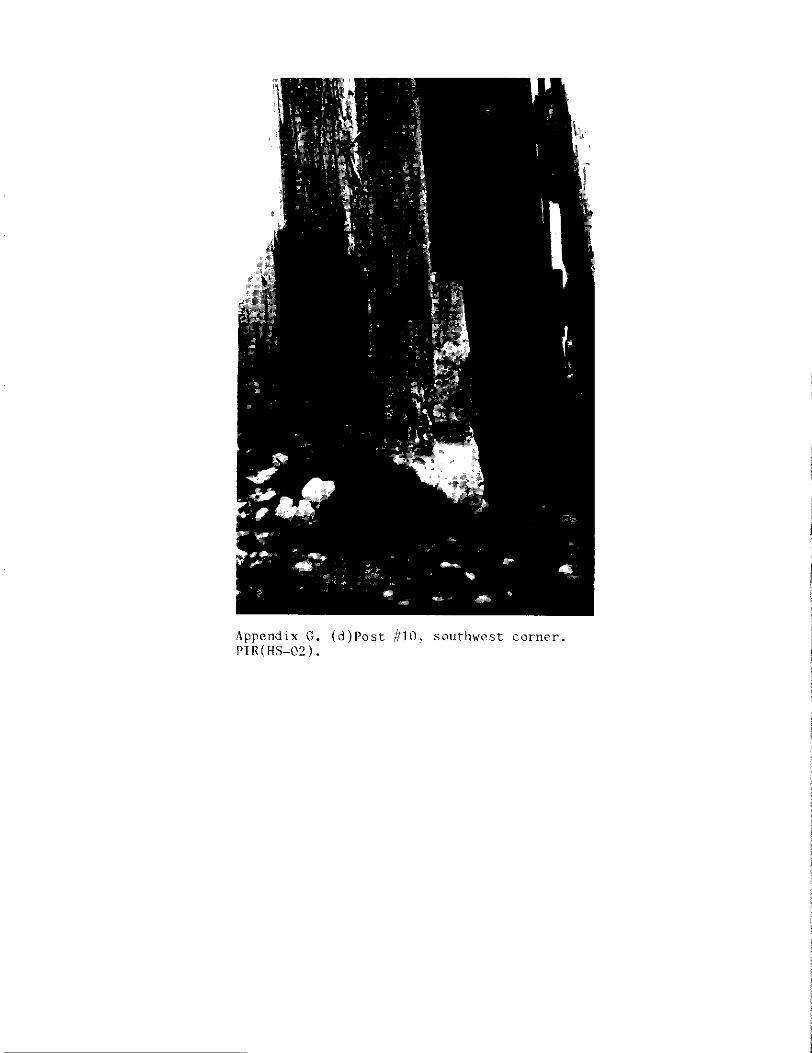
Appendix G. (d)Post #Ill, southwest corner. PTR ( HS-02) •

Bibliography
Carden, Marie. "Paint Analysis and Recommendations for the Harry S Truman Home National Historic Site, Independence, Missouri." Boston North Atlantic Historic Preservation Center, National Park Service, May 1986. Photocopy.
Cockrell, Ren. Historic Structures Report: History and Significance Harry S Truman National Historic Site, Indepenc'.er.ce, Missouri. Omaha: National Park Service Midwest Regional Office, 1984.
Historic Re: source Study: The Trumans of Independence, Harry S Truman National Historic Site, Inc'ependence, Missouri. Omaha: National Park Service Midwest Regional Office, 1985.
Fire Insurance Maps of Independence, Missouri. Sanborn Map Company, Pelha.m, New York, September, 1907; August, 1916; August, 1926, and August, 1926 Corrected to 1949.
Graham, Lawrence S. "Truman Garage, Independence, Missouri." Kansas City, Harper and Kerr Structural Engineers, P.A., July 26, 1985. Photocopy.
"Truman Garage, Independence, Missouri." Kansas City, Harper and Kerr Structural Engineers, P.A., February 26, 1986. Photocopy.
Lee, Michael and Alan 0 'Bright. "Physical Investigation Report Trurr.an Home (HS-01) Harry S Truman NHS." Orr.aha, National Park Service Cultural Resources Management Division, July 24-26, 1984. Photocopy.
Mueller, John M. Letter to National Park Service, Re: Truman Residence, Carriage house wiring, 12 July 1985.
National Park Service. "Physical Investigation Report & Treatment Proposal, Truman Carriage Hom:e (HS-2) Foundation Harry S Truman National Historic Site, Independence, Mi sscmr i. 11 Omaha, Cultural Resources Management Division, April, 1986. Photocopy.
O'Bright, Alan. Exterior Woodwork Number 2 Preservation Tech Notes. Orr.aha, Midwest Regional Office, National Park Service, June 18, 1986. Photocopy.
Panethiere, M.A. "Electrical Report, Harry S Truman House." Kansas City, Associated Engineering Consultants, March 31, 1986. Photocopy.
- 201 -
J
Restoration Associates, a division of Solomon Claybaugh Young Architects, Inc. "Analysis of Condition Report HS-1 Truman Home, Truman Home National Historic Site." Kansas City, February 14, 1985.
Ruger, A. Bird's Eye View of the City of Independence, Jackson County, Missouri. 1
United States Department of the Interior. "Handicap Access Survey of Harry S Truman National Historic Site. 11 A7615 (DSC-MPG). Denver, National Park Service, March 22, 1985. Photoccpy.
"Alternative to the Stair-Trac for the handicapped access of Harry S Trumai' National Historic Site." H,3015 (MWR-PC). Omaha National Park Service, May 29, 1986. Photcccpy.
- 202 - ~u.s. G.P.O. 1987-757-894