anchoring foot mechanisms for sampling and mobility in
TRANSCRIPT

Proceedings of the 2011 IEEE International Conference on Robotics and Automation
May 9·13, 2011, Shanghai, China ICRA Communications
Anchoring Foot Mechanisms for Sampling and Mobility in Microgravity
Aaron Parness
NASA Jet Propulsion Laboratory, California Institute of Technology, Pasadena, CA email: [email protected]
Abstract- An omni-directional anchoring mechanism is presented that can withstand forces greater than 100 N on natural rock surfaces. The anchor builds upon previous development of microspine toes for climbing robots. This work utilizes an opposed octagonal scissor configuration with rows of 30 toes on each lever arm, splayed around a central housing. This anchor design is being developed for the Lemur lIb mobile robot. The anchor can also be used to support a coring drill. The work enables both mobility and sampling in microgravity environments, like the surface of Near Earth Asteroids.
I. INTRODUCTION
Asteroids and comets have garnered increasing interest from space agencies as evidenced by the recent string of missions to these bodies including DAWN, Deep Impact, NEAR, Hayabusa, Rosetta and EPOXI, as well as extensive ground based observation programs. The composition and characteristics of these small bodies contain direct evidence of the formation of our solar system, and organic molecules identified on these bodies may hold secrets about the beginnings of life on our own planet [1], [2]. These bodies also pose a small, but catastrophic threat to our civilization should a collision with the Earth occur. To date, NASA missions have only observed these bodies remotely, but future science missions will strive to perform in-situ measurements through the use of landers, rovers, and sample acquisition technologies. The information gathered from these efforts will help answer fundamental science questions and collect the engineering data necessary to pave the way for human visitation.
After the cancellation of the Constellation program in 2010, President Obama prioritized a manned mission to a near-earth asteroid as a stepping stone to Mars exploration [3], echoing the recommendation of the Augustine Committee [4]. To make these missions safe for the astronauts, robotic analysis of the composition, physical properties, and toxicity of these bodies must be performed beforehand. NASA's human space flight program has been studying potential rover designs and landers for small bodies to deploy in 'Scout' missions. In preparation for these and future scientific missions, JPL is investing in the advancement of microspine anchor technology; preliminary results shown in Figure 1.
In order to sample from, maneuver on, or anchor to these bodies, current technology must be matured. This paper
Aaron Parness is a member of the Robotics the NASA Jet Propulsion Laboratory, Pasadena, [email protected]
Section at CA, USA.
Fig. I. This Inverted Hang Test for the omni·directional anchor prototype shows the 8 kg Lemur lIb robot [10] supported from the macroscopically Hat, but rough surface of a vesicular basalt rock. The gripping mechanism utilizes a total of 240 microspine toes distributed on eight levered arrays. A whippletree mechanism evenly distributes forces to each array despite differences in displacement. Each toe has an independent suspension that lets it conform locally to find the best spot on the rock to grip.
focuses on one of these technologies, a microspine based gripping mechanism that could be used as the end effector of a long robotic boom or as the foot of a mobile rover. Microspines were invented at the Biomimetics and Dexterous Manipulation Laboratory at Stanford University for use on climbing robots [5], [6]. Each microspine toe consists of a steel hook embedded in a rigid frame with a compliant suspension system. By arraying tens or hundreds of these microspine toes, large loads can be supported and shared between many attachment points. Since each spine has its own suspension structure, it can stretch and drag to find
978-1-61284-380-3/11/$26.00 © 2011 IEEE 6596
ICRA Communications
a suitable asperity to grip. The hooks can attach to both convex and concave asperities like pits, protrusions, or even sloped rock faces [7]. This allowed robots like RiSE [8] and Spinybot [9] to climb flat, rough, vertical surfaces such as exterior brick and stucco walls. Microspine toes support loads in one preferred direction, so the feet of these robots were designed as arrays of 20-40 toes in a line across the vertical wall to resist the forces of gravity. Expanding the capability of these systems to small bodies requires two advancements:
1) using array configurations that can resist forces in any
direction
2) transitioning the technology for use on natural rock
surfaces, where there is additional large-scale rough
ness and variation
This paper will first provide the motivation for the development of this technology from its current form to an omni-directional anchor for use in space. The design of the anchor and the results of testing with the initial prototype are then discussed, and the transition of the anchors to the 8 kg quadruped platform, Lemur lIb [10]. Finally, the current conclusions and development plan for the future are presented.
II. MOTIVATION
A. Microgravity Sampling and Mobility
Asteroids range in size from specs of dust to large spherical objects several hundred kilometers in diameter. On the largest asteroids, which reside primarily in the main asteroid belt, there is enough gravity to use traditional methods of mobility like wheeled driving or legged walking (although some argue that the reduced gravity makes a hopping/jumping rover a more capable choice). However, there are vastly fewer large asteroids than small, especially in near earth orbits [11]. A near-earth asteroid is favored for human missions (and robotic Scout missions) because of the reduced travel time to and from the body. On these smaller bodies, the escape velocity can be so small « 10 cm/s) that wheeled driving, walking, or jumping becomes infeasible due to the risk of the robot accidentally jettisoning itself into space. This risk would also force conventional rovers to move prohibitively slow. The technology described here allows for an alternative to these gravity-dependent mobility methods. Taking cues from climbing robots, future mobile asteroid rovers may use anchoring systems to stay attached to the surface, allowing faster and safer locomotion. Omnidirectional microspine anchors provide an easily controllable, reliable, mechanical mechanism for these rovers to utilize on consolidated natural rock surfaces.
The microgravity environment is similarly challenging for sample acquisition, particularly drilling. A crucial parameter for an extraterrestrial drill is the required weight on bit (WOB) [12]. The European Space Agency's RosettaiPhilae mission to Comet 67P/Churyumov-Gerasimenko carries a drill, SD2, with a required WOB of lOON [13]. On the 500 meter diameter asteroid Itokawa recently visited by the
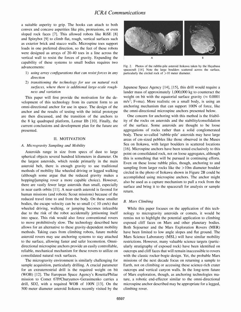
Fig. 2. Photos of the rubble-pile asteroid Itokawa taken by the Hayabusa spacecraft [14]. Note the large boulders scattered across the surface, particularly the circled rock of > 10 meter diameter.
Japanese Space Agency [14], [15], this drill would require a lander mass of approximately 1,000,000 kg to counteract the weight on bit with the equatorial surface gravity (::::: 0.0001 m/s2; F=ma). More realistic on a small body, is using an anchoring mechanism that can support lOON of force, like the omni-directional microspine anchors presented below.
One concern for anchoring with this method is the friability of the rocks on asteroids and the stability/consolidation of the surface. Some asteroids are thought to be loose aggregations of rocks rather than a solid conglomerated body. These so-called 'rubble-pile' asteroids may have large areas of cm-sized pebbles like those observed in the Muses Sea on Itokawa, with larger boulders in scattered locations [16]. Microspine anchors have been tested exclusively to this point on consolidated rock, not on loose aggregates, although this is something that will be pursued in continuing efforts. Even on these loose rubble piles, though, anchoring to and sampling from larger rocks like the > 10m diameter boulder circled in the photo of Itokawa shown in Figure 2B could be accomplished using microspine anchors. The anchor might also be used as a capture mechanism to pull a rock from the surface and bring it to the spacecraft for analysis or sample return.
B. Mars Climbing
While this paper focuses on the application of this technology to microgravity asteroids or comets, it would be remiss not to highlight the potential application to climbing exposed cliff faces on Mars and other planetary bodies. Both Sojourner and the Mars Exploration Rovers (MER) have been limited to low angle slopes and flat ground. The Mars Science Laboratory (MSL) will have similar mobility restrictions. However, many valuable science targets (particularly stratigraphy of exposed rock) have been identified on outcrops and cliff faces that will remain inaccessible to rovers with the classic rocker-bogie design. Yet, the probable Mars missions of the next decade focus on returning a sample to Earth, not on climbing or accessing these science-rich crater outcrops and vertical canyon walls. In the long-term future of Mars exploration, though, as anchoring technologies mature, a robotic end-effector similar to the omni-directional microspine anchor described may be appropriate for a legged, climbing rover.
6597

ICRA Communications
Fig. 3. A single microspine toe consists of a rigid frame. embedded steel hook. and elastic flexures that allow the spine to both translate and rotate relative to its neighbors in order to find a suitable asperity on the rock to grip. These toes were originally designed for vertical climbing of manmade rough surfaces at Stanford University [5] .
Fig. 4. This close up shot of a single 30-toe array shows the ability of the toes to conform to the rock in both the normal and transverse directions. Only about 10-20% of toes typically grip a surface. but this is sufficient to support appreciable loads. as shown in Figures I and 5.
III. RESULTS AND DISCUSSION
The core component of the gripper is the microspine toe, originally developed at Stanford university [6], [7]. A toe, pictured in Figure 3, is fabricated in a batch of 50-100 using the shape deposition manufacturing process (SDM). SDM uses sequential deposition and milling steps to create multi-material parts with embedded components [ l7]. Each of the toes shown here is comprised of a rigid frame, compliant flexures, and an embedded steel hook. Of these, the compliant flexures are the most important to the design. These flexures allow each hook to move relative to its neighbors on its own suspension system. This way, when an array of toes is dragged along a surface, individual hooks can grasp asperities in the rock at various points as they encounter good holding locations and share a small portion of the overall load. This independent stretching and force balancing can be seen in Figure 4, where neighboring toes have found various pits and bumps on the rock to grasp.
A line of these toes can support loads in only one direction.
To create an omni-directional anchor, eight rows of 30 toes each were attached to an octagonal center housing. Each row of toes was held in place by a leg that acts as a lever with the pivot point at the outer rim of the housing. Several lever dimensions were tried empirically to determine a good ratio of lengths. The center of the housing is hollow, providing an accessible location for mounting the anchor to the leg of a robot or placing a sampling tool like a coring drill. Both of these scenarios are being explored currently. Future versions of the anchor are being designed to include additional macroscale compliance elements between each row of toes and the central housing. A mechanism is also being developed to push each leg into contact with the surface during attachment. A whippletree mechanism has been implement to provide a passive, force balancing system for distributing forces evenly to the legs of the gripper regardless of where they grasp relative to one another.
Several tests were performed with the initial prototype. Figure 1 shows an Inverted Hang Test where the gripper was attached to the robot and hung upside down to demonstrate the resistive force of the anchor. In Figure I, the anchor is supporting an 80N inverted load from the macroscopically flat surface of a vesicular basalt rock. Rock Lift Tests were also performed, where the anchor was lowered onto a rock, and then used to lift the rock off the ground. Due to the lever mechanism of the leg, no preloading of the toes is necessary, only contact with the rock. The pivot action of the legs push the steel hooks into the surface and translates them slightly towards the center of the housing. Figure 5 shows the gripper lifting a 103 N rock from a convex surface of a rock. In this configuration, approximately 10-30% of the toes successfully gripped asperities on the rock (small pits, ledges, and other topography). Future iterations of the design should increase this percentage. The gripper was placed on the rock and lifted successfully without applied preload ten consecutive times in various locations. After gripping and lifting the rock, the rock could be kicked, bounced, and shaken without causing detachment, demonstrating the gripper's resistance to perturbation forces. This also indicates a higher maximum gripping capability is likely possible. However, current testing methods require a human leaning out over the rock to lift the weight, thus heavier rocks have not been tested at this time due to limitations of strength and the risk of back injury. An automated test setup is under design for weights up to 1000 N that will also accommodate lateral loading tests. A movie showing a Rock Lift Test and subsequent kicking and bouncing of the rock is available at [18]. Tests have been run on vesicular basalts and A' a lava rocks.
To test the omni-directional behavior of the anchor, the gripper was also placed on vertical rock faces and loaded in a downward shear direction, a Vertical Shear Test. In this configuration, the upper half of the gripper acts similarly to the feet of the climbing robots from which the technology originated, while the lower half of the gripper does not contribute. However, because the microspine toes are stronger in shear than adhesion, the overall load that was resisted was
6598

ICRA Communications
Fig. S. This Rock Lift Test shows the prototype anchor supporting more than 107 N from the convex surface of a rock. This demonstration does not require that the anchor be preloaded or specially configured. Simply placing the anchor into contact with the rock, then pulling up from the center is sufficient to engage a sufficient percentage of the steel hooks. This test was repeated ten times in various locations on the rock without failure.
roughly uniform regardless of the direction of application. Future work will replicate this style of gripper with a
robotic actuator for attachment to the Lemur lIb climbing robot platform shown in Figure 6 [10]. With omni-directional anchors on each of its four feet, the robot will be able to climb both vertical and inverted rock surfaces, like the walls of canyons and the interiors of caves.
IV. CONCLUSIONS
An omni-directional anchoring mechanism was presented that can withstand over 100 N of force in all loading directions on natural rock surfaces. This holding force is sufficient for a legged rover like Lemur lIb to climb vertical and inverted rock surfaces, or to support the necessary weight on bit of an extraterrestrial drill like the European Space Agency's SD2. This technology is limited to consolidated rocks that are large enough for the gripper to engage, but even rubble-pile asteroids like Itokawa are known to have many boulders of sufficient size in addition to the regolith and pebble-sized rocks.
V. ACKNOWLEDGMENTS
The research was carried out at the Jet Propulsion Laboratory, California Institute of Technology, under a contract with the National Aeronautics and Space Administration. Copyright 2011 California Institute of Technology. Government sponsorship acknowledged. The author additionally thanks the Jet Propulsion Laboratory Office of the Chief Scientist and Chief Technologist for their support of this work.
REFERENCES
[I ] D. Des-Marais, 1. Nuth et aI., The NASA Astrobiology Roadmap, Astrobiology, vol 8, no 4. 2008.
Fig. 6. The Lemur lIb platform was originally developed in 2005 for climbing walls using human rock-climbing tools and strategies. New research funding is resurrecting this platform for use with the omnidirectional anchors discussed in this paper. The robot weighs 8 kg on Earth and can be supported statically by a single anchor in good contact with a vesicular rock surface. Future work will equip the robot with four anchors to enable both vertical and inverted climbing tests in the field at local cliff and cave locations in the Mojave desert.
[2J D. Lauretta. Astrobiology Priorities for Primitive Asteroids, posted on NAI website 2009.
[3J B. Obama. Speech at Johnson Space Center, April 16, 2010. [4J N. Augustine et al .. Seeking a Human Spaceflight Program Worthy of
a Great Nation. NASA. Washington. DC. 2009. [5J bdml.stanford.edu [6J A. Asbeck. S. Kim. M. Cutkosky. W Provancher, M. Lanzetta. Scaling
Hard Vertical Surfaces with Compliant Microspine Arrays. The International Journal of Robotics Research vol 25. no 12. 2006. 1165-]]79.
[7J A. Asbeck, S. Kim, A. McClung, A. Parness. M. Cutkosky. Climbing Walls with Microspines, IEEE ICRA, Orlando. FL, 2006.
[8J M. Spenko et al .• Biologically Inspired Climbing with a Hexapod Robot. J. of Field Robotics. vol 25. no 4-5. 2008. 223-242.
[9J S. Kim, A. Asbeck, M. Cutkosky, W Provancher, Spinybotll: Climbing Hard Walls with Compliant Microspines. 12th International Conference on Advanced Robotics. Seattle, 2005.
[lOJ B. Kennedy et al. Lemur lib: a Robotic System for Steep Terrain Access. Climbing and Walking Robots. , Springer Berlin Heidelberg. 2006.
[II J R. Landis. D. Korsmeyer, P Abell. D. Adamo. A Piloted Orion Flight to a Near-Earth Object: A Feasibility Study, AIAA Space Ops. 2009.
[l2J K Zacny et al., Drilling Systems for Extraterrestrial Subsutface Exploration Astrobiology, vol 8. no 3, 2008.
[l3J A. Finzi et al.. SD2 - How to Sample a Comet. Space Science Reviews, vol 128, 2007. 281-299.
[14 J A. Fujiwara. et al .. The Rubble-Pile Asteroid ltokawa as Observed by
Hayabusa, Science. vol 312. no 5778. 2006. 1330 - 1334. [15 J S. Abe, et al.. Mass and Local Topography Measurements of ltokawa
by Hayabusa. Science. vol 312. no 5778. 2006. 1344 - 1347. [16J H. Yano. et al.. Touchdown of the Hayabusa Spacecraft at the Muses
Sea on ltokawa. Science, vol 312, no 5778, 2006 , 1350-1353.
[17J R. Men F. Prinz, K. Ramaswami, M. Terk. and L. Weiss. Shape Deposition Manufacturing Proceedings of the 1994 Solid Freeform
Fabrication Symposium, 1994. [18J http://www.youtube.comlwatch?v=8v4QRRP5rjE
http://www-robotics.jpl. nasa.govlvideoslpeople VideoList.cfm
6599