analytical considerations for reducing the emittance with ... · analytical considerations for...
TRANSCRIPT

Analytical considerations for reducing the emittance with longitudinally variable bends
Stefania Papadopoulou* +, Yannis Papaphilippou* *CERN, +University of Crete
ESLS 2014 Workshop, Grenoble

Contents
• TME cell
• Longitudinally variable bends
• Dipole profiles • Analytical parameterization of a variable bend TME cell -Parameterization with the drift lengths -Parameterization with the emittance • Conclusions and next steps
2

TME cell
The balance between radiation damping and quantum excitation results in the equilibrium betatron emittance. Using a theoretical minimum emittance, TME cell, low emittance values can be achieved. The horizontal emittance of the beam can be generally expressed as:
3

Longitudinally variable bends
Considering only the half dipole for simplicity (from 0 till L/2) as the other is symmetric and then dividing the dipole into two parts of different bending radii can be expressed as:
Approaching the evolution of the uniform dipole’s dispersion invariant assists in approaching its emittance behaviour in order to reduce it. The evolution of the dispersion invariant along the dipole guides the dipole profile choice for the emittance reduction.
Bending angle of half dipole: 4
References: J. Guo and T. Raubenheimer, (EPAC02), Y.Papaphilippou, P. Elleaume, PAC'05, R. Nagaoka, A.F. Wrulich, (NIM A575, 2007), C.-x Wang (PRST-AB, 2009)

Dipole profiles
Fixing the dipole’s characteristics in accordance to the design’s constraints leads to the dependence of FTME either on r or l . In this way the highest FTME value for a specific design can be found.
Emittance reduction factor
FTME depends only on r and l
as the bending radii of the uniform and of the chosen profile are the same (as well as their length) and thus are simplified .
Bending radii ratio Lengths ratio
If the dipole’s characteristics are not fixed FTME is a function of r and l.
Bending angle of the dipole q
Dipole’s length L
Minimum bending radius r1
(maximum magnetic field 1.8T)
2p/100 0.6 m 5.4 m
5
Step profile Trapezium profile
CLI
C

The parameterization of the emittance reduction factor FTME with the bending radii ratio r and the lengths ratio l,
always for l>0.1 so that the lengths L1, L2 are comparable. The black contour lines correspond to different values of horizontal phase advances (for the uniform dipole it is mx,TME=284.5o).
6
Step profile Trapezium profile
The maximum possible emittance reduction for the step with negative bend is insignificant compared to the one achieved for the step profile.
Comparison of the non-uniform dipole profiles’ reduction factors when l=0.1 (there the highest reductions are localized)
The trapezium profile gives the highest emittance reduction

7
Comparison of non-uniform dipole profiles when fixing the dipole’s characteristics (bending angle, length and minimum bending radius)
L=0.6m, Nd=100, r1=5.4m
L=1.5m, Nd=100, r1=5.4m
FTME(r) or FTME(l) l(r) or r(l) FTME(r,l)

Analytical parameterization of a variable bend TME cell (only for the trapezium profile)
Knowing the dipole’s characteristics it is important to fix some more parameters in order to produce the numerical results for the CLIC DR lattice design: • The quadrupoles’ length is set to lq = 0.2m. • The maximum dipole field is set to 1.8T (minimum bending radius = 5.4m) • The maximum pole tip field of the quadrupoles and the sextupoles is Bmaxq = 1.1T and
Bmaxs = 0.8T respectively. • The required output normalized emittance for Nd = 100 dipoles is 500nm and the operational
energy of the CLIC Damping Rings complex of 2.86 GeV.
Fixing those parameters the free parameters left are the drift space lengths s1, s2, s3 and the emittance. The stability criterion is governing every result and is included in the feasibility constraints:
8
Reference: F. Antoniou and Y. Papaphilippou, PRSTAB, 17, 064002 , 23 June 2014
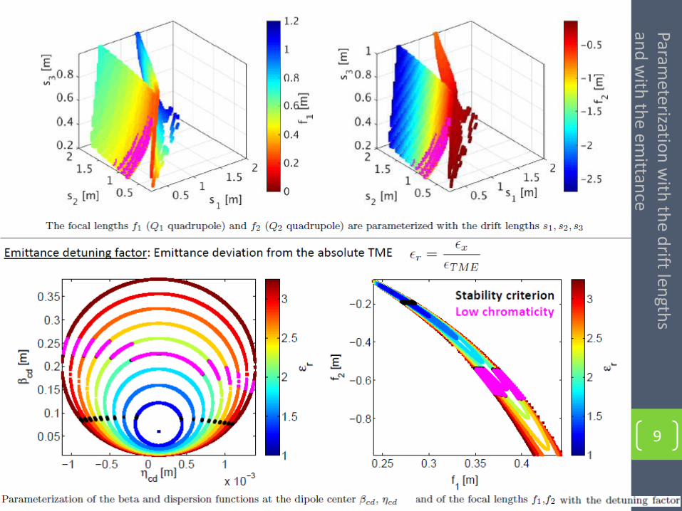
9
Parameterizatio
n w
ith th
e drift len
gths
and
with
the em
ittance

Conclusions and next steps
Dipole profiles Total cell’s length Lcell [m] FTMEmax (CLIC design) l(FTMEmax) (CLIC design)
Step 2.6 3.13 0.25
Trapezium 2.6 5.75 0.1
• The highest emittance reduction is given by the trapezium profile, concurrently it provides feasible-low
chromaticity solutions for low detuning factors .
• The agreement with the simulation code MADX validates the analytical solutions for both profiles, specially for the thin lens approximation.
• Studies on the fringe fields created by the individual parts of the non-uniform dipoles will provide a better understanding of their behaviour.
• A further improvement of the final emittance values can be achieved when taking into consideration the
collective effects, such as the Intrabeam scattering IBS that in the regime of ultralow emittances with high bunch charge has a significant impact on the emittance limits.
10

Thank you!
Special thanks to F. Antoniou for her valuable help.
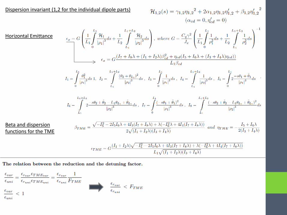
Horizontal Emittance
Dispersion invariant (1,2 for the individual dipole parts)
Beta and dispersion functions for the TME
Co
mp
arison
with
MA
DX
cod
e for th
e trap
ezium
pro
file
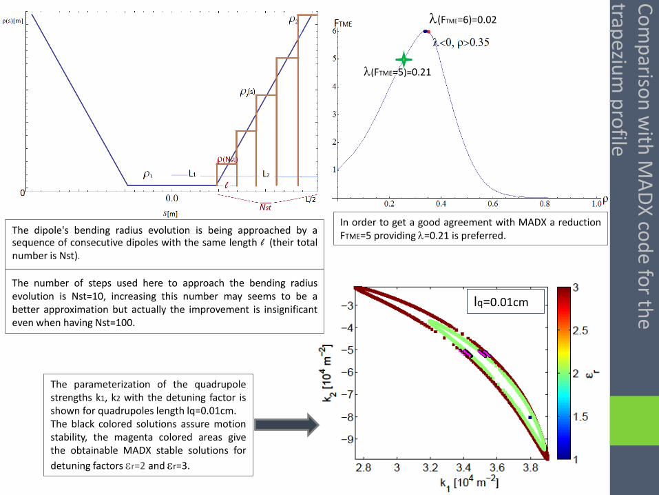
l(FTME=5)=0.21
l(FTME=6)=0.02
lq=0.01cm
The dipole's bending radius evolution is being approached by a sequence of consecutive dipoles with the same length l (their total number is Nst).
The number of steps used here to approach the bending radius evolution is Nst=10, increasing this number may seems to be a better approximation but actually the improvement is insignificant even when having Nst=100.
The parameterization of the quadrupole strengths k1, k2 with the detuning factor is shown for quadrupoles length lq=0.01cm. The black colored solutions assure motion stability, the magenta colored areas give the obtainable MADX stable solutions for
detuning factors er=2 and er=3.
In order to get a good agreement with MADX a reduction FTME=5 providing l=0.21 is preferred.