analysis the speed control of bldc motor drive using - ijera.com
TRANSCRIPT

MS. JULI SINGH / International Journal of Engineering Research and Applications
(IJERA) ISSN: 2248-9622 www.ijera.com
Vol. 2, Issue 3, May-Jun 2012, pp.2868-2884
2868 | P a g e
ANALYSIS THE SPEED CONTROL OF BLDC MOTOR DRIVE
USING SENSORS
MS. JULI SINGH Institution: Rungta college of Engg. & Technology
Department: Electrical Engg.
______________________________________________________________________________
ABSTRACT Brushless DC Motor (BLDC) is one of the best electrical drives that have increasing popularity, due to their
high efficiency, reliability, good dynamic response and very low maintenance.Due to the increasing demand for
compact & reliable motors and the evolution of low cost power semiconductor switches and permanent magnet
(PM) materials, brushless DC motors become popular in every application from home appliances to aerospace
industry. The conventional techniques for controlling the stator phase current in a brushless DC drive are practically
effective in low speed and cannot reduce the commutation torque ripple in high speed range.
This paper presents the PI controller for speed control of BLDC motor. The output of the PI controllers is
summed and is given as the input to the current controller. The mathematical modeling of BLDC motor is also
presented. The BLDC motor is fed from the inverter where the rotor position and current controller is the input.
The complete mathematical model of the proposed drive system is developed and simulated using
MATLAB/Simulink software. The operation principle of using component is analysed and the simulation results are
presented in this to verify the theoretical analysis.
Keywords:BLDCM- BRUSHLESS DIRECT CURRENT MOTOR, PM- PERMANENT MAGNET, PI-
Proportional Integrated controller, VR- Variable Reluctance.
1. INTRODUCTION OF BLDCM The increase in energy prices spurs higher demands of variable speed PM motor drives. Also, recent rapid
proliferation of motor drives into the automobile industry, based on hybrid drives, generates a serious demand for
high efficient PM motor drives, and this was the beginning of interest in BLDC motors.
BLDC motors, also called Permanent Magnet DC Synchronous motors, are one of the motor type that have
more rapidly gained popularity, mainly because of their better characteristics an performance [2]. These motors
are used in a great amount of industrial sectors because their architecture is suitable for any safety critical
applications.
In general, the overall system consists of three parts: (1) power conversion three phase inverters, (2) BLDC
motor and load, (3) speed, torque, and current controllers and (4) Position Control by using sensors. Therefore,
exact understanding of each part is a prerequisite for analysis and prediction of the overall system operation.
Several simulation models have been proposed for the analysis of BLDC motor drives. These models are
based on state-space equations, Fourier series, and the d-q axis model [9–12].The brushless DC motor is a
synchronous electric motor that, from a modeling perspective, looks exactly like a DC motor, having a linear
relationship between current and torque, voltage and speed (rad/sec). It is an electronically controlled commutation
system, instead of having a mechanical commutation, which is typical of brushed motors. Additionally, the
electromagnets do not move, the permanent magnets rotate and the armature remains static. This gets around the
problem of how to transfer current to a moving armature. In order to do this, the brush-system/commutator assembly
is replaced by an intelligent electronic controller, which performs the same power distribution as a brushed DC
motor [3]. BLDC motors have many advantages over brushed DC motors and induction motors, such as a better
speed versus torque characteristics, high dynamic response, high efficiency and reliability, long operating life (no
brush erosion), noiseless operation, higher speed ranges, and reduction of electromagnetic interference (EMI).
The control of BLDC motors can be done in sensor or sensorless mode, but to reduce overall cost of
actuating devices, sensorless control techniques are normally used. The advantage of sensorless BLDC motor
control is that the sensing part can be omitted, and thus overall costs can be considerably reduced.
The disadvantages of sensorless control are higher requirements for control algorithms and more
complicated electronics [3]. All of the electrical motors that do not require an electrical connection (made with
brushes) between stationary and rotating parts can be considered as brushless permanent magnet (PM) machines [4],

MS. JULI SINGH / International Journal of Engineering Research and Applications
(IJERA) ISSN: 2248-9622 www.ijera.com
Vol. 2, Issue 3, May-Jun 2012, pp.2868-2884
2869 | P a g e
which can be categorized based on the PMs mounting and the back-EMF shape. The PMs can be surface mounted
on the rotor (SMPM) or installed inside of the rotor (IPM) [5], and the back-EMF shape can either be sinusoidal or
trapezoidal.
A PMAC motor is typically excited by a three-phase sinusoidal current, and a BLDC motor is usually
powered by a set of currents having a quasi-square waveform [6,7].
Brushless DC motors were developed from conventional brushed DC motors with the availability of solid
state power semiconductors. Brushless DC motors are similar to AC synchronous motors. The major difference is
that synchronous motors develop a sinusoidal back EMF, as compared to a rectangular, or trapezoidal, back EMF
for brushless DC motors. Both have stator created rotating magnetic fields producing torque in a magnetic rotor.
The remainder of the paper is arranged as follows. Section -2 discussAnalysis of BLDC motor drive
system. Next, section -3 explains the problem identification in bldc motor drive, in this section we discuss problem
related to position and speed control of BLDC motors drive using sensors and also describeproblems occur in
selecting the value of PI controller gain Section -4 , discuss methodology of BLDC motor drive. Finally in section -5
shows the results analysis of BLDC motor drive and conclusion.
2. Analysis of BLDC Motor Drive System
Figure 1 shows the overall system configuration of the three-phase BLDC motor drive. The three phase inverter
topology is a six-switch voltage-source configuration with constant dc-link voltage (Vdc), which is identical with the
induction motor drives and the permanent magnet ac motor drives. The analysis is based on the following
assumption for simplification [12]:
1. The motor is not saturated.
2. Stator resistances of all the windings are equal, and self- and mutual inductances are constant.
3. Power semiconductor devices in the inverter are ideal.
4. Iron losses are negligible.
Fig 1 Brushless D.C. Motor drive
3. PROBLEM IDENTIFICATION IN BLDC MOTOR DRIVE

MS. JULI SINGH / International Journal of Engineering Research and Applications
(IJERA) ISSN: 2248-9622 www.ijera.com
Vol. 2, Issue 3, May-Jun 2012, pp.2868-2884
2870 | P a g e
PROBLEM RELATED TO SPEED CONTROL OF BRUSHLESS D.C. MOTOR DRIVE USING SENSORS
1. Low-cost Hall-effect sensors are usually used.
2. Electromagnetic variable reluctance (VR) sensors
3. Accelerometers have been extensively applied to measure motor position and speed.
Hall-effect sensors
These kinds of devices are based on Hall-effect theory, which states that if an electric current- carrying conductor is
kept in a magnetic field, the magnetic field exerts a transverse force on the moving charge carriers that tends to push
them to one side of the conductor. A build-up of charge at the sides of the conductors will balance this magnetic
influence producing a measurable voltage between the two sides of the conductor.
To rotate the BLDC motor the stator windings should be energized in a sequence. It is important to know
the rotor position in order to understand which winding will be energized following the energizing sequence. Rotor
position is sensed using Hall-effect sensors embedded into the stator
The connecting principle between the brushless motor and this sensor is reminiscent of the miniaturized
magnetic angular encoder based on 3-D Hall sensors. A permanent magnet is fixed at the end of a rotary shaft and
the magnetic sensor is placed below, and the magnet creates a magnetic field parallel to the sensor surface. This
surface corresponds to the sensitive directions of the magnetic sensor. Three-phase brushless motors need three
signals with a phase shift of 120° for control, so a closed-loop regulation may be used to improve the motor
performance.
PROBLEMS OCCUR IN SELECTING THE VALUE OF PI CONTROLLER GAIN
SPEED CONTROLLER The rotor rotation of the BLDC motor, while the motor speed depends only on the amplitude of the applied voltage.
The required speed is controlled using a speed controller. The speed controller is implemented as a conventional PI
controller.
Proportional Integral Controller Design
The model of PI speed controller is given by,
G(s) =Kp+(Ki / s)
Where G(S) is the controller transfer function which is torque to error ratio in s-domain, Kp is the proportional gain
and Ki is the integral gain. The tuning of these parameters is done using Ziegler Nichols method using the phase and
gain Margin specifications. The specifications of the drive application are usually available in terms of percentage
overshoot and settling time. The PI parameters are chosen so as to place the poles at appropriate locations to get the
desired response.
These parameters are obtained using Ziegler Nichols method which ensures stability. From the dynamic
response obtained by simulation, the percentages overshoot Mp and settling time ts which are the measures of
Transient behaviors are obtained. The speed loop of the typical BLDC motor under no load condition.
The closed loop transfer function of the system is given by
T(s) = (Kp S + Ki)/ [J (s2 + (B + Kp/J) S + (Ki /J )]
Where T(S) is the closed loop transfer function and Kp, Ki Are the PI controller parameters, J is the moment of
inertia And B is the coefficient of friction.
Kp = 2ζ. Ѡn J.B
Ki = J.Ѡn
ζ = Damping Ratio, Risetime=tr=(𝝅 –𝜱)
𝝎𝒏 𝟏−𝜻𝟐 ,
Phase Angle = Φ = 𝐭𝐚𝐧−𝟏( 𝟏−𝜻𝟐
𝜻) Maximum Overshoot = Mp = 𝐞
𝟏−𝛇𝟐
−𝛇 𝛑

MS. JULI SINGH / International Journal of Engineering Research and Applications
(IJERA) ISSN: 2248-9622 www.ijera.com
Vol. 2, Issue 3, May-Jun 2012, pp.2868-2884
2871 | P a g e
Fig. 2 Speed loop showing the PI controller and BLDC
S2+ 2ζωn + ωn
2 = 0 (second order system characteristics equation)
T(s) = (Kp S + Ki ) /[J(s2 + (B + Kp/J)S + Ki /J)]
T(s) = G(s).H(s) = ( 𝒌𝒑 𝑺+𝒌𝒊
𝑺). (
𝟏
𝑱𝑺+𝑩)
= 𝐊𝐩 𝐒+𝐊𝐢
𝐒 ( 𝐉𝐒+𝐁 ) =
𝐊𝐩 𝐒+𝐊𝐢
𝐉 𝐒𝟐+ 𝐁+𝐊𝐩
𝐉 𝐒+(
𝐊𝐢
𝐉)
ωn= 𝐊𝐢
𝐉
2ζωn = 𝐁+𝐊𝐩
𝐉
ζ = 𝐁+𝐊𝐩
𝟐 𝐉
𝐉
𝐊𝐢 = (
𝐁+𝐊𝐩
𝟐)
𝟏
𝐉.𝐊𝐢
Here,
J = Rotor Inertia of BLDC Motor = 0.087 kg.m2
B = Viscous Friction of BLDC Motor = 0.005 N.m.s
S. N. Ki Kp ζ ωn Φ Rise Time tr Peak Overshoot Mp
1. 0 0 0 0 0 0 0
2. 10 5 0.085 0.339 85.12 280.71 0.765
3. 10 15 0.254 0.339 75.28 319.38 0.438
4 10 20 0.339 0.339 70.18 344.34 0.323
5. 10 30 0.509 0.339 50.40 444.14 0.159
6. 10 50 0.848 0.339 32.01 823.68 0.0066
7. 10 80 0.356 0.339 0 0 0
8. 30 50 0.489 0.587 60.73 232.14 0.172
9. 50 50 0.379 0.758 67.73 160.05 0.276
Table.1 Compare chart for selecting Ki and Kpvalue.
Note: Proportional control will reduce the steady state error, but at the cost of large overshoot. Furthermore, Kp
(Proportional Gain) will never completely eliminate the steady state error. For we need to try integral control. Let
implement PI controller and start with a small Ki.
To reduce the settling time, we can increase Ki but by doing this transient response will get worse (i.e. large
overshoot).
The effects of increasing each of the controller parameters Kp, KD and Ki can be summarized as following table2.
S.N Response Rise Time Settling Time Overshoot Steady State Error
1. Kp Decrease NT Increase Decrease
2. Ki Decrease Increase Increase Eliminate

MS. JULI SINGH / International Journal of Engineering Research and Applications
(IJERA) ISSN: 2248-9622 www.ijera.com
Vol. 2, Issue 3, May-Jun 2012, pp.2868-2884
2872 | P a g e
3. KD NT Decrease Decrease NT
Table 2 Controlling parameters Kp, KD and Ki can be summarized NT = Not definite trend (i.e Minor Change)
4. METHODOLOGY
MATHEMATICAL MODELING OF THE AC MACHINE The electrical system dynamics may be described by two voltage equation:
ν1 = r1 i1 + pλ1 ----------------------- (5)
ν2 = r2 i2 + pλ2 ----------------------------------- (6)
Where p is the Heaviside notation for the time differentiation operator d/dt. Assume that the stator flux linkages are
linearly related to the currents, the flux linkage λ1 and λ2 may be expressed:
λ1 = L11 i1 + L12 i2 + λpm1 ------------------------ (7)
λ2 = L21 i1 + L22 i2 + λpm2 ----------------------------------- (8)
The stator windings are symmetric, i.e. they have the same total self-inductance, resistance, and number of turns.
Since the self –inductance is the same for windings, L11 and L22 in (7) and (8) will denote as Lss. Since the stator
windings are tightly wound on highly permeable stator steel, the numerical value of the mutual inductance is nearly
equal to the total self-inductance. However, since the magnetic axes are in opposite directions for positive current in
each winding, the mutual inductance is negative. A minus sign and the symbol Lm will replace L12 and L21 in
equation no. (7) and (8). The symmetry and configuration of the windings indicate that both have the same
permanent–magnet component of flux linkage but with opposite signs. The symbol λm will be used for the
permanent-magnet flux linkage term.
ν1 = rsi1 + Lss p i1 -Lm p i2 + pλm ---------------------- (9)
ν2 = rsi2 - Lss p i1 + Lm p i2 - pλm ------------------------------ (10)
In equation (9) and (10), pλmcan be expressed as ωr(dλm/dθr) and represents the no-load or back emf of the
motor. The induced voltage due to armature reaction are related to the terms containing Lss and Lm which, when
added to the back emf , establish the total induced voltages in the stator windings.
For the mechanical system, the torque developed by the electromagnetic system counters the inertial
acceleration torque, the torques due to windage and friction ( modeled as being proportional to rotor velocity), and
the load torque , i.e.
Te=Jpωr + B ωr +TL --------------------- (11)
The interaction of currents in the stator electrical system with the magnetic field of the rotor permanent magnets
creates an electromagnetic torque, Te. The electromagnetic torque may be established by expressing the partial
derivative of the co energy w.r.t. position. The resulting expression for the electromagnetic torque is:
Te = (i1 –i2) 𝑑𝜆𝑚
𝑑𝜃𝑟 -
𝑑𝑊𝑝𝑚
𝑑𝜃𝑟 --------------------- (12)
Where Wpm represented the coupling field energy due to the permanent magnets. Total derivatives because λm and
Wpm are functions only of θr. The first term on the right-hand side of equation (12) represents the electromagnetic
torque produced by the interaction of electric current in the stator windings with the magnetic field of the rotor
permanent magnets. The second term represents a torque due to the attraction between the rotor permanent magnet
and the stator steel and acts to drive the rotor to a position having the lowest permanent magnet component of
coupling field energy.
This torque hereafter referred to as the cogging torque Tec, ensures that the rotor position of the unexcited
motor is such that an electromagnetic torque sufficient for starting is developed when the stator windings are
suddenly energized.
The cogging torque does not depend upon the stator currents and is a function only of θr. It is incorporated
in the state model as a position dependent load torque. The cogging torque is assumed to very sinusoidalw.r.t. Rotor
position. The peak value of the cogging torque and the rotor position at which the cogging torque is maximum were
measured experimentally for the given four-pole motor. The variation of cogging torque w.r.t. rotor position is not
exactly sinusoidal; the only time that the cogging torque is important is during start-up.
In practically, the cogging torques acts to drive the rotor of an unexcited machine to a position such that
when the source voltage is suddenly applied, the resulting electromagnetic torque accelerates the rotor in the proper
direction. After some algebraic manipulation, (9), (10) and (11) may be expressed in state-model from as:
pi1 =
1
Lss (1−k2) [(ν1 -rs ) + k( ν2 - rs i2) – (1-k) ωr
dλm
dθr ] -------------(13)

MS. JULI SINGH / International Journal of Engineering Research and Applications
(IJERA) ISSN: 2248-9622 www.ijera.com
Vol. 2, Issue 3, May-Jun 2012, pp.2868-2884
2873 | P a g e
pi2 = 1
Lss (1−k2) [k (ν1 -rsi1 ) + ( ν2 - rs i2) + (1-k) ωr
dλm
dθr ] --------------(14)
pωr= 1
𝐽 (Te – B ωr - TL) ------------- (15)
pθr = ωr --------------- (16)
Where k =𝐿𝑚 𝐿𝑠𝑠 denotes a coefficient of coupling. In equation (13), (14) and (15), the applied stator voltages ν1
and ν2 and the load torque TL represent inputs variables.
θr = electrical rotor position and ωr= electrical rotor velocity .. i.e.θr= (4/2) θrm=2 θrm for the 4-pole motor, or θr =
(P/2) θrmfor a P-pole device. However, the right-hand side of equation (12) must be multiplied by the number of pole
pairs. In subsequent computer studies, the electrical rotor velocity ωr is plotted rather than the actual rotor velocity
ωrm.
PERFORMANCE OF BLDC MOTOR
The actual shaft output torque is:
Tload = Tem – Tlosses
Where Tlosses is the total losses due to friction, windage, and iron losses. Dropping the amplitude signs, we have
Tem = 𝑚𝑝
2 m Iג
Speed-torque curve:- The voltage equation can be simplified as
V = E + IR
Substituting the relations of E -ωr and T-I, we obtain.
ν = 𝑃
2ωrλm+
2𝑅
𝑚𝑝𝜆𝑚 Tem
ωr = 2𝜈
𝑝𝜆𝑚 -
4𝑅
𝑚 𝑝𝜆𝑚 2 Tem
Ѡr
Ѡo P
O Tload + Tlosses Tem
Fig. 3 Torque-Speed curve is drawn for a constant voltage
Mechanical input Allows you to select either the load torque or the motor speed as mechanical input. Note that if you select and apply
a load torque, you will obtain as output the motor speed according to the following differential equation that
describes the mechanical system dynamics:
Te= J𝑑
𝑑𝑡ωr + F ωr +Tm
This mechanical system is included in the motor model.
However if you select the motor speed as mechanical input then you will get the electromagnetic torque as output,
allowing you to represent externally the mechanical system dynamics. Note that the internal mechanical system is
not used with this mechanical input selection and the inertia and viscous friction parameters are not displayed.
Block diagram of BLDC Motor Drive:
This circuit uses the AC7 block of SimPower System library. It models a brushless DC motor drive with a
braking chopper for a 3HP motor.
The permanent magnet synchronous motor (with trapezoidal back-EMF) is fed by a three phase inverter, which is
built using a Universal Bridge Block.
The speed control loop uses a PI regulator to produce the torque reference for the current control block.
Brushless D.C. Motor Drive (SIMULINK)
Implement brushless DC motor drive using Permanent Magnet Synchronous Motor (PMSM) with
trapezoidal back electromotive force (BEMF)

MS. JULI SINGH / International Journal of Engineering Research and Applications
(IJERA) ISSN: 2248-9622 www.ijera.com
Vol. 2, Issue 3, May-Jun 2012, pp.2868-2884
2874 | P a g e
Description:
The high-level schematic shown below is built from six main blocks. The PMSM, the three-phase inverter, and the
three-phase diode rectifier models are provided with the SimPowerSystems library.
The speed controller, the braking chopper, and the current controller models are specific to the Electric
Drives library. It is possible to use a simplified version of the drive containing an average-value model of the
inverter for faster simulation.
The speed controller, the braking chopper, and the current controller models are specific to the Electric Drives
library. It is possible to use a simplified version of the drive containing an average-value model of the inverter for
faster simulation.
Fig.4Modelling analysis of Brushless Direct Current Motor Drive with
MATLAB/SIMULINK.
Here SC - Stator Current
RS – Rotor Speed
ET – Electromagnetic Torque
DCBV – D.C. Bus Voltage
MS. JULI SINGH / International Journal of Engineering Research and Applications
(IJERA) ISSN: 2248-9622 www.ijera.com
Vol. 2, Issue 3, May-Jun 2012, pp.2868-2884
2875 | P a g e
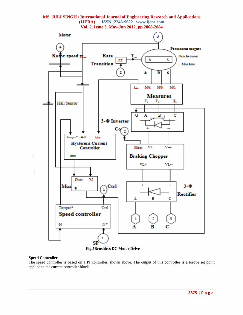
Fig.5Brushless DC Motor Drive
Speed Controller
The speed controller is based on a PI controller, shown above. The output of this controller is a torque set point
applied to the current controller block.

MS. JULI SINGH / International Journal of Engineering Research and Applications
(IJERA) ISSN: 2248-9622 www.ijera.com
Vol. 2, Issue 3, May-Jun 2012, pp.2868-2884
2876 | P a g e
Fig 6 Speed Controller
Current Controllers
In the BLDC motor drive, duty cycle controlled voltage PWM technique and hysteresis current control technique
can be regarded as the main current control strategies.
In this thesis bipolar hysteresis current control is used for obtaining the fast dynamic responses during transient
states.

MS. JULI SINGH / International Journal of Engineering Research and Applications
(IJERA) ISSN: 2248-9622 www.ijera.com
Vol. 2, Issue 3, May-Jun 2012, pp.2868-2884
2877 | P a g e
Fig.7 Current Controller
5. RESULTS and CONCLUSION
Case: I For without Torque load Condition (Speed and Torque)
Torque Parameters: Time (sec.) 0 1 2
Torque (Nm) 0 0 0
Speed Parameters Speed (rad/sec) 50 78.5 50
0 0.5 1 1.5 2 2.5
x 106
-6
-4
-2
0
2
4
6
8
Time(Sec.)
Sta
tor C
urren
t (A
mp
.)
Stator Current (Amp.) V/S Time(Sec.)

MS. JULI SINGH / International Journal of Engineering Research and Applications
(IJERA) ISSN: 2248-9622 www.ijera.com
Vol. 2, Issue 3, May-Jun 2012, pp.2868-2884
2878 | P a g e
Fig 8 Wave forn analysis for Without Torque Condition (Speed and Torque)
0 0.5 1 1.5 2 2.5
x 106
-20
0
20
40
60
80
Time (Sec.)
Ro
tor S
peed
(ra
d/s
ec.)
Rotor Speed(rad/sec.) V/S Time (Sec.)
0 0.5 1 1.5 2 2.5
x 106
-10
-5
0
5
10
Time(Sec.)
Ele
ctr
om
ag
neti
c T
orq
ue(N
m)
Electromagnetic Torque(Nm) V/S Time(Sec.)
0 0.5 1 1.5 2 2.5
x 106
0
100
200
300
400
500
600
Time(Sec.)
DC
Bu
s V
olt
ag
e (
Vo
lt)
DC Bus Voltage (Volt) V/s Time(Sec.)

MS. JULI SINGH / International Journal of Engineering Research and Applications
(IJERA) ISSN: 2248-9622 www.ijera.com
Vol. 2, Issue 3, May-Jun 2012, pp.2868-2884
2879 | P a g e
Stator Current of BLDC Motor
This graph represents the stator current ( ia in Amp) vs time (in sec.) of Brushless Dc Motor. Stator current
waveform is not smooth because some harmonics are present in input.
Rotor Speed of BLDC Motor
This graph represents the rotor speed (in rpm) vs time (in sec) of BLDC motor.
Speed of themotor is varied in between Rated Speed 78.5 rad/sec. at 0 sec but without Torque. BLDC Motor is
8poles Motor and frequency is 50 Hz, then
Speed(N) = (120*frequency) / Numbers of poles.
Ѡm = 2π* N
Electromagnetic Torque of BLDC motor
As shown in the following figure, the speed precisely follows the acceleration ramp. At t = 0.2 s, the nominal load
torque is applied 1.4 Nm to the motor. At t = 1 s, the speed set point is changed to 0 rpm. The speed increases to 0
rpm. At t = 1.2 s., the mechanical load passes from 0 N.m.
DC Bus voltage of BLDC Motor
This graph represents the variation of dc bus voltage (in volts) with respect to time (in sec.). This D.C. bus voltage is
obtained from Three- phase rectifier circuits.
Case: II For Transient load Condition (Speed and Torque)
Torque Parameters: Time (sec.) 0 1 2
Torque (Nm) 0.7 1.4 0.7
Speed Parameters Speed (rad/sec) 50 78.5 50
0 0.5 1 1.5 2 2.5
x 106
-8
-6
-4
-2
0
2
4
6
8
Time(sec.)
Sta
tor C
urren
t(A
mp
.)
Stator Current (Amp.) V/S Time(sec.)
0 0.5 1 1.5 2 2.5
x 106
-20
0
20
40
60
80
Time (Sec.)
Ro
tor S
peed
(ra
d/s
ec.)
Rotor Speed (rad/sec.) V/S Time (Sec.)

MS. JULI SINGH / International Journal of Engineering Research and Applications
(IJERA) ISSN: 2248-9622 www.ijera.com
Vol. 2, Issue 3, May-Jun 2012, pp.2868-2884
2880 | P a g e
Fig 9 Waveform for Transient load Condition (Speed and Torque)
Case: IIIKi=0 and Kp=0,
For Transient load Condition (Speed and Torque)
Torque Parameters: Time (sec.) 0 1 2
Torque (Nm) 0.7 1.4 0.7
Speed Parameters Speed (rad/sec) 78.5 78.5 78.5
When proportional controller gain or Integral controller gain is zero (absence of PI controller) at transient load
conditions following waveforms are obtained.
0 0.5 1 1.5 2 2.5
x 106
-10
-5
0
5
10
15
Time(Sec.)
Ele
ctr
om
ag
neti
c T
orq
ue (
Nm
)
Electromagnetic Torque (Nm) V/S Time(Sec.)
0 0.5 1 1.5 2 2.5
x 106
0
100
200
300
400
500
600
Time(sec.)
DC
Bu
s V
olt
ag
e (
Vo
lt)
DC Bus Voltage (Volt) V/S Time(sec.)
0 0.5 1 1.5 2 2.5
x 105
-2
-1
0
1
2
Time(sec)
Sta
to
r C
urren
t(A
mp
)
Stator Current(Amp) V/s Time(Sec)

MS. JULI SINGH / International Journal of Engineering Research and Applications
(IJERA) ISSN: 2248-9622 www.ijera.com
Vol. 2, Issue 3, May-Jun 2012, pp.2868-2884
2881 | P a g e
Fig 10 Waveform for analysis for PI controller gain at Ki&Kp zero
0 0.5 1 1.5 2 2.5
x 105
-300
-200
-100
0
100
Time(sec)
Ro
to
r S
peed
(ra
d/sec)
Rotor Speed(rad/sec) V/s Time(sec)
0 0.5 1 1.5 2 2.5
x 105
-2
0
2
4
Time(sec)
Electro
ma
gn
etic T
orq
ue(N
m)
Electromagnetic Torque(Nm) V/s Time(Sec)
0 0.5 1 1.5 2 2.5
x 105
0
200
400
600
Time(sec)
DC
B
us V
olta
ge (V
olt)
DC Bus Voltage (Volt) V/s Time(sec)

MS. JULI SINGH / International Journal of Engineering Research and Applications
(IJERA) ISSN: 2248-9622 www.ijera.com
Vol. 2, Issue 3, May-Jun 2012, pp.2868-2884
2882 | P a g e
Case: IV Ki=10 and Kp=50,
For Transient load Condition (Speed and Torque)
Torque Parameters: Time (sec.) 0 1 2
Torque (Nm) 0.7 1.4 0.7
Speed Parameters Speed (rad/sec) 78.5 78.5 78.5
0 0.2 0.4 0.6 0.8 1 1.2 1.4 1.6 1.8 2 2.2
x 105
-10
-5
0
5
10
Time(sec)
Sta
to
r C
urren
t(A
mp
)
Stator Current(Amp) V/s Time(sec)
0 0.2 0.4 0.6 0.8 1 1.2 1.4 1.6 1.8 2 2.2
x 105
-20
0
20
40
60
80Rotor Speed (rad/sec) V/s Time(sec)
Time(Sec)
Ro
to
r S
peed
(ra
d/s
ec)
0 0.2 0.4 0.6 0.8 1 1.2 1.4 1.6 1.8 2 2.2
x 105
-10
0
10
20Electromagnetic Torque(Nm) V/s Time(sec)
Time(sec)
Ele
ctro
ma
gn
etic
To
rq
ue(N
m)

MS. JULI SINGH / International Journal of Engineering Research and Applications
(IJERA) ISSN: 2248-9622 www.ijera.com
Vol. 2, Issue 3, May-Jun 2012, pp.2868-2884
2883 | P a g e
Fig. 11 Waveform for analysis PI controller gain for Transient load Condition (Speed &Torque)
From varies values of Ki and Kp minimum peak overshoot and maximum rise time is obtained at a value of
Ki=10 and Kp=50.
Hence we obtained following waveform at transient condition.
Therefore, we can conclude that in presence of Ki and Kp or PI controller, we obtained a better and stable
stator current vs time, rotor speed vs time, electromagnetic torque vs time and DC bus voltage vs time curve.
CONCLUSION In this thesis, a mathematical model of brushless DC motor is developed. The simulation of the brushless
DC motor was done using the software package MATLAB/SIMULINK.
In this thesis a review of position control using Hall sensor methods for BLDC motors has been presented.
It is obvious that the control for BLDC motors using position sensors, such as shaft encoders, resolvers or Hall-
effect probes, can be improved by means of the elimination of these sensors to further reduce cost and increase
reliability.
In this thesis we have done result analysis and found results in different load conditions. We have also analyzed the
steady state condition and transient condition. The steady state condition was found to be very close to the transient
condition.
6. REFRENCES
[1] Bose, B. K., Modern Power Electronics and AC Drives, Prentice-Hall, N.J., 2002.
[2] Becerra, R.C.; Ehsani, M. High-Speed Torque Control of Brushless Permanent Magnet Motors.
IEEE Trans. Ind. Electron. 1988, 35, 402-406.
[3] Hubik, V.; Sveda, M.; Singule, V. On the Development of BLDC Motor Control Run-Up Algorithms for
Aerospace Application. In Proceedings of the 13th Power Electronics and Motion Control Conference (EPE-
PEMC 2008), Poznan, Poland, September 2008; pp. 1620-1624.
[4] T.J.E. Miller, "Brushless permanent magnet and reluctance motor drive", Oxford, 1989.
[5] Bianchi, N.; Bolognani, S.; Jang, J.H.; Sul, S.K. Comparison of PM Motor Structures and Sensorless Control
Techniques for Zero-Speed Rotor Position Detection. IEEE Trans. Power Electron. 2007, 22, 2466-2475. .
[6] Su, G.J.; McKeever, J.W. Low-Cost Sensorless Control of Brushless DC Motors with Improved
Speed Range.IEEE Trans. Power Electron. 2004, 19, 296-302.
[7] Damodharan, P.; Vasudevan, K. Indirect Back-EMF Zero Crossing Detection for SensorlessBLDC Motor
Operation. In Proceedings of the International Conference on Power Electronics and Drives Systems (PEDS
2005), Kuala Lumpur, Malaysia, November 2008; pp. 1107-1111.
0 0.2 0.4 0.6 0.8 1 1.2 1.4 1.6 1.8 2 2.2
x 105
0
200
400
600DC Bus Voltage(Volt) V/s Time(sec)
Time(sec)
DC
B
us V
oltage(V
olt)

MS. JULI SINGH / International Journal of Engineering Research and Applications
(IJERA) ISSN: 2248-9622 www.ijera.com
Vol. 2, Issue 3, May-Jun 2012, pp.2868-2884
2884 | P a g e
[8]. J.S. Mayer, student or O. Wasynezuk, senior member. Analysis and modelling of a single-phase brushless
D.C. motor drive system , IEEE Transactions on Energy Conversion, vol. 4, No. 3, September 1989.
[9] P. Pillay and R. Krishnan, “Modeling, simulation, and analysis of permanent-magnet motor drives, part II: the
brushless DC motor drive,” IEEE Trans. on Industry Applications, vol. 25, no. 2, pp. 274–279, March/April
1989.
[10] R. Carlson, M. Lajoie-Mazenc, and C. dos S. Fagundes, “Analysis of torque ripple due to phase commutation
in brushless DC machines,” IEEE Trans. on Industry Applications, vol. 28, no. 3, pp. 632–638, May/June
1992.
[11] P. D. Evans and D. Brown, “Simulation of brushless DC drives,” Proc. of the IEEE, vol. 137, no. 5, pp. 299–
308, September 1990.
[12] S. K. Safi, P. P. Acarnley, and A. G. Jack, “Analysis and simulation of the high-speed torque performance of
brushless DC motor drives,” Proc. of the IEE, vol. 142, no. 3, pp. 191–200, May 1995.
FIRST AUTHOR BIOGRAPHIES
Miss Juli Singh is working as an Assistant Professor (EEE department) of Bhilai Institute of technology,
Raipur. She obtained B.E. (Electrical Engg.) from MPCCET, Bhilai (2008). M.E. (Specialization - Power
Electronics) in CSVT university (Only project submission remaining).