analysis on the structural systems for drift … on the structural systems for drift control of tall...
TRANSCRIPT


1
Analysis on the Structural Systems for Drift Control of Tall Buildings
due to Wind Load: Critical Investigation on Building Heights
Shafiqul Islam1 and Md. Mashfiqul Islam2
ABSTRACT
The great metropolises of the world share common dilemmas. Increased
population densities due to the migration of people from the countryside to the
cities, combined with the rising price of developable land and the environmental
politics of the day provide the urban planners with no better solution than to build
higher. In Bangladesh this scenario is getting familiar from past few decades. As a
result, constructions of tall buildings of more than 20 stories become necessary
and already practiced especially for Dhaka city to support the current demands.
As building increases in height, the lateral displacement of the building due to
wind loads becomes one of the primary concerns. An excessive lateral
displacement or inter-story drift causes the failure of both structural and non-
structural elements. In design specifications, the calculated displacement at the
top of a high-rise building and inter-story drifts at the final stage of the structural
design process must be checked not to exceed specified limits with respect to
building height as well as individual story height. To this end, this paper
investigates the performance and efficiency of special structural systems in drift
control of 20, 30, 40 and 50 stories high tall buildings due to wind load. Large
Scale Bracing system, Shear wall with Bracing system, shear wall frame system
and Tube in Tube with Shear wall systems are critically analyzed to investigate the
drift control for those heights. The Shear wall with Bracing system showed the
most acceptable results in drift control for all heights.
Keywords: Structural systems, tall buildings, drift control, inter-story drift, wind
load.
1. INTRODUCTION
Drift control of tall building refers to maintain the lateral deflection of tall building at
sufficiently low level to allow the proper functioning of nonstructural components
1 Lecturer, Department of Civil Engineering, AUST. 2 Assistant Professor, Department of Civil Engineering, AUST.

2
(elevators, escalators etc.) and to avoid distress in the structure, to prevent excessive
cracking due to deflection and consequent loss of stiffness. The adopted structural system
should be sufficiently stiff to prevent dynamic motions (due to wind and seismic loading)
becoming large enough to cause discomfort to occupants, prevent delicate work being
undertaken, affect sensitive equipment and to avoid any redistribution of load to non-load
bearing portions or infills. For buildings having small number of story, lateral loads
rarely affect the design. But when the height of the building increases, the increase in size
of structural members and the possible rearrangements of the structure to account for
loads incurs a cost premium (Sazzad and Kamruzzaman, 2002).
From a structural engineers point of view, a tall building may be defined as one that,
because of its height, is affected by lateral forces due to wind or earthquake actions to an
extent that they play an important role in the structural design as well as deciding
appropriate structural system to withstand those forces. One simple parameter to estimate
the lateral stiffness of a building is the drift index, defined as the ratio of maximum
deflection at the top of the building to the height due to lateral forces (Smith & Coull,
1991). Drifts (lateral deflections) of concern in serviceability checking arise primarily
from the effects of wind. As per ASCE/SEI 7-05 (2006), the limit for drift index is below
1/600 (0.001667) to 1/400 (0.0025). These limits generally are sufficient to minimize the
damage to cladding and nonstructural walls and partitions. Smaller drift limits may be
appropriate if the cladding is brittle. Another important parameter to evaluate the stiffness
of tall building is inter-story drift values. An absolute limit on inter-story drift may also
need to be imposed in light of evidence that damage to non-structural partitions, cladding
and glazing may occur if the inter-story drift exceeds about 10 mm (3/8in i.e. 0.375in)
unless special detailing practices are made to tolerate movement (ASCE/SEI 7-05, 2006).
Many components can accept deformations that are significantly larger. For conventional
structures the preferred acceptable range is 0.0015 to 0.003 and sufficient stiffness must
be provided to ensure that the top deflection does not exceed the value under extreme
loading condition (Smith & Coull 1991, Islam et. al. 2011, Islam et. al. 2012).
Wind load presents the most critical lateral loading for modern tall buildings, which have
lightweight skeletons that cause uncomfortable horizontal movements for occupants.
Also, wind is not constant either with height or with time and is not uniform over the
sides of a building. So, windy weather creates a variety of problems in tall buildings,
causing concern for buildings owner and engineers alike. Where, excessive vibration due

3
to this load is a major obstacle in design and construction of a modern tall building. It
should be limited to prevent both structural and nonstructural damage (El-Leithy et. al.,
2011).
Concrete shear walls are widely used in tall buildings to provide lateral rigidity and to
perform satisfactory in resisting loads due to wind without incurring structural or
architectural damage (Park and Park, 1997). Shear walls are often parts of the elevator
and service cores, while the frames are arranged in plan, and they are linked by floor
slabs such that the building will deflect as a structure with rigid section. When a wall-
frame structure is loaded laterally, the wall deflects in a flexural mode with concavity
downward and a maximum slope at the top, and the frame deflects in a shear mode with
concavity upward and a maximum slope at the base. Accordingly, the deflected shape of
the whole structure has a flexural profile in the lower part and a shear profile in the upper
part. The interacting forces cause the wall to restrain the frame near the base and the
frames to support the wall at the top, and thus reduce the lateral drift of the structure. The
major advantages of a wall-frame structure depend on the amount of horizontal
interaction, which is governed by the relative stiffness of the walls and frames, and the
height of the structure. Since the elastic capacity of the structure is limited by the material
strength, suvival generally relies on the ductility of structural system to dissipate energy
(Pall and Marsh, 1981). The key idea in limiting the wind drift in a tall building is by
changing the structural form of the building into something more rigid and stable to
confine the deformation and increase stability. The stiffness (rigidity) and stability
requirements become more important as the height of the structure increases, and they are
often the dominant factors in the design (El-Leithy et. al. 2011). An important problem
associated with wind induced motion of buildings is concerned with human response to
vibration and perception of motion. At this point it will suffice to note that humans are
surprisingly sensitive to vibration to the extent that motions may feel uncomfortable even
if they correspond to relatively low levels of stress and strain. Therefore, for most tall
buildings serviceability considerations govern the design and not strength issues (Mendis
et. al. 2007). The major factors that has to be taken into account in selecting the
appropriate structural system includes the internal planning, the material and method of
construction, the external architectural treatment, the planned location and routing of the
service systems, the nature and magnitude of horizontal loading and the height and
proportions of the building. Common structural systems are framed system, braced-frame
system, rigid-frame system, infilled-frame system, flat-plate and flat-slab system, shear

4
wall and coupled-shear wall system, shear wall-frame system, framed-tube (tubular)
system, tube-in-tube and bundled-tube system, braced-tube system, outrigger-braced
system, suspended structure system, core structure system, space structure system, hybrid
structure system etc. In this paper, some special structural systems are critically analyzed
to identify the sustainable option to control the drift of tall buildings. This research puts
light on the performance, efficiency and compatibility of those structural systems for tall
buildings to be built in the skyline of Bangladesh.
2. PROBLEM STATEMENT
Four structural systems are selected to investigate the drift pattern due to lateral loading;
they are large scale braced-frame system, shear wall with bracing system, shear wall-
frame system and tube in tube system which showed lower drift index values in the
analyses done in Islam et. al. 2012. The prototype models considering reinforced cement
concrete (RCC) structures are created for 20, 30, 40 and 50 storied tall building for these
four systems.
RCC tall buildings of different structural system are modeled considering 20, 30, 40 and
50 storeys with story height 10ft using ETABS 9.2, which is a renouned structural
analysis software. The sizes of the beams are 12in x 15in, 12in x 18in, 12in x 21in and
12in x 24in and the sizes of the columns are 24in x 24in, 27in x 27in, 30in x 30in and
33in x 33in for 20, 30, 40 and 50 storied buildings repectively. The thickness of the shear
walls are considered 12in, 14in, 16in and 18in and the cross sections of the bracings are
considered 12in x 12in, 15in x 15in, 18in x 18in and 21in x 21in for 20, 30, 40 and 50
storied buildings repectively. The thickness of the slab for all structural system are
maintained 6in. The wind load is applied as per UBC 1994 (Uniform Building Code)
which is equivalent to BNBC 1993 considering exposure condition A and wind velocity
210 km/hr. Load combinations are applied as per BNBC 1993 specifications. The dead
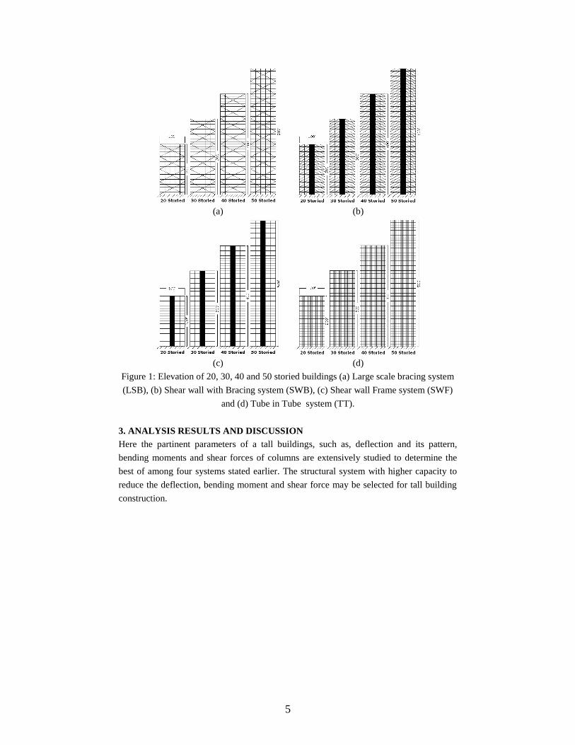
load is considered 40 psf and live load 60 psf. Figure 1 shows elevations of different
structural systems investigated in this study and Figure 2 shows typical floor plans.
5
(a) (b)
(c) (d)
Figure 1: Elevation of 20, 30, 40 and 50 storied buildings (a) Large scale bracing system
(LSB), (b) Shear wall with Bracing system (SWB), (c) Shear wall Frame system (SWF)
and (d) Tube in Tube system (TT).
3. ANALYSIS RESULTS AND DISCUSSION
Here the partinent parameters of a tall buildings, such as, deflection and its pattern,
bending moments and shear forces of columns are extensively studied to determine the
best of among four systems stated earlier. The structural system with higher capacity to
reduce the deflection, bending moment and shear force may be selected for tall building
construction.

6
3.1 Building Height Effect
The effect of height of tall buildings are clearly visible in Figures 3, 4, 5 and 6. The drift
of Large Scale Bracing system (Figure 3) increases significantly with heights and also
this is found for it’s inter-story drift. The inter-story drift of Large Scale Bracing system
shows a zigzag pattern which is definitely due to the bracing-beam-column connections.
It is also found from the inter story drift results that the first story drift is significantly
higher which may become desastarous as it happens for a soft story. This is due to the
absence of shear wall. Again after 40 stories the wind speed is high enough that makes a
abrupt variation of the inter-story drift patten. The top lateral deflection for 20. 30, 40 and
50 stories are 1.61in, 3.65in, 6.91in and 11.5in respectively and maximum inter story
drifts are 0.12in, 0.18in, 0.25in and 0.32in respectively .
Figure 2: Typical floor plan of Shear wall-frame and Tube in Tube system.
For the Shear wall with Bracing system (Figure 4) the lateral deflection is found less
increament with heights and the inter-story drift is found to become almost constant after
midheight which is a indication of stable control of the drift due to lateral loading. The
top lateral deflection for 20. 30, 40 and 50 stories are 0.65in, 2.16in, 5.35in and 10.23in
respectively and maximum inter-story drifts are 0.03in, 0.07in, 0.14in and 0.24in
respectively.
The Shear wall Frame system (Figure 5) less control on lateral deflection compared to
above systems and the inter story drifts show a extensively large drift at the mid height
with a decreasing pattern to the upper stories. This system provides information on the

7
less control on the inter-drifts. The top lateral deflection for 20. 30, 40 and 50 stories are
1.64in, 4.57in, 9.41in and 15.96in respectively and maximum inter-story drifts are 0.1in,
0.2in, 0.29in and 0.38in respectively.
Tube in Tube system shows similar pattern of lateral deflection like Large Scale Bracing
system (Figure 6). The inter-story drift of this system shows a inceasing tendency in
lower stories and a gradual decreasing tendency towards the upper stories. Tube in Tube
system shows a significant drift control for 50 storied building compared to lower
storieds. The top lateral deflection for 20. 30, 40 and 50 stories are 3.19in, 6.39in,
10.08in and 10.49in respectively and maximum inter-story drifts are 0.26in, 0.286in,
0.37in and 0.286in respectively.
Figure 3: Lateral deflection and Inter-story drift of Large Scale Bracing system
Figure 4: Lateral deflection and Inter-story drift of Shear wall with Bracing system
0
5
10
15
20
25
30
35
40
45
50
0 5 10 15 20
No
. o
f s
tori
es
Lateral deflection (inch)
SWB, 20 St.
30 St.
40 St.
50 St.
0
5
10
15
20
25
30
35
40
45
50
0 0.5 1
No
. o
f s
tori
es
Inter-story drift (inch)
SWB 20 St.
30 St.
40 St.
50 St.

8
Figure 5: Lateral deflection and Inter-story drift of Shear wall-frame system
Figure 6: Lateral deflection and Inter-story drift of Tube in Tube system.
3.2 Bending Moment Effect
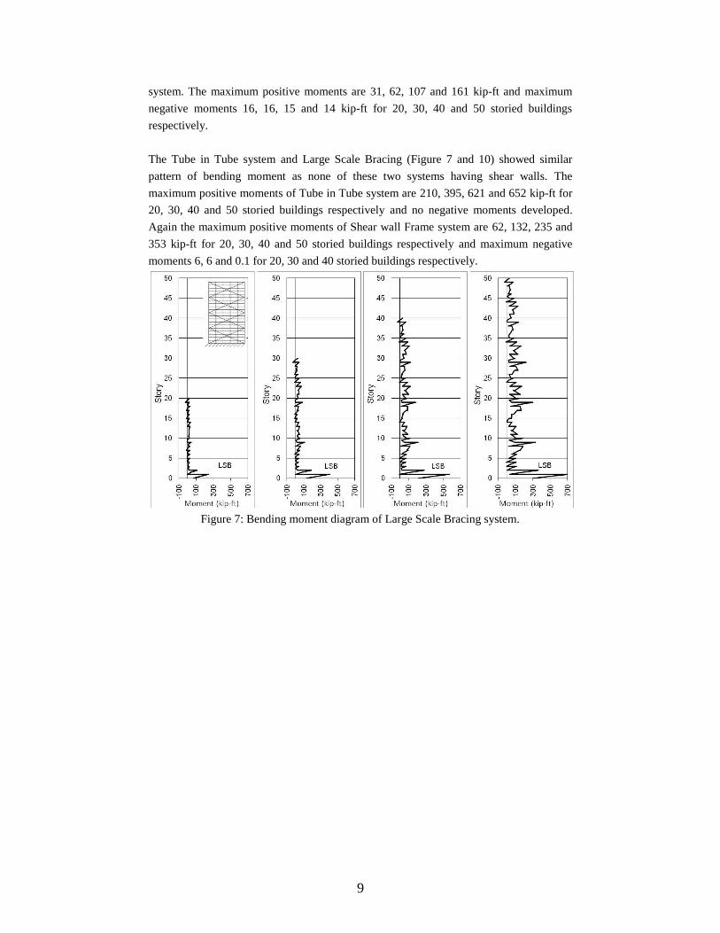
The bending moment diagrams of the column A6 (Figure 2) of the tall buildings are
shown in Figures 7, 8, 9 and 10. The bending moment diagram of Large Scale Bracing
system (Figure 7) shows a different pattern with heights. The bending moments of
columns have found lower in the story where the bracings are connected and larger in
other stories. The maximum positive moments are 241, 406, 572 and 510 kip-ft and
maximum negative moments 22, 25, 25 and 25 kip-ft for 20, 30, 40 and 50 storied
buildings respectively.
The Shear wall with Bracing system shows a uniform decreasing pattern of bending
moment with height and also highest moment resisting capacity compared to other
0
5
10
15
20
25
30
35
40
45
50
0 5 10 15 20
No
. o
f s
tori
es
Lateral deflection (inch)
SWF, 20 St.30 St.40 St.50 St.
0
5
10
15
20
25
30
35
40
45
50
0 0.5 1
No
. o
f s
tori
es
Inter-story drift (inch)
SWF, 20 St.30 St.40 St.50 St.
0
5
10
15
20
25
30
35
40
45
50
0 5 10 15 20
No
. o
f s
tori
es
Lateral deflection (inch)
TT 20 St.
30 St.
40 St.
50 St.0
5
10
15
20
25
30
35
40
45
50
0 0.5 1
No
. o
f s
tori
es
Inter-story drift (inch)
TT 20 St.
30 St.
40 St.
50 St.
9
system. The maximum positive moments are 31, 62, 107 and 161 kip-ft and maximum
negative moments 16, 16, 15 and 14 kip-ft for 20, 30, 40 and 50 storied buildings
respectively.
The Tube in Tube system and Large Scale Bracing (Figure 7 and 10) showed similar
pattern of bending moment as none of these two systems having shear walls. The
maximum positive moments of Tube in Tube system are 210, 395, 621 and 652 kip-ft for
20, 30, 40 and 50 storied buildings respectively and no negative moments developed.
Again the maximum positive moments of Shear wall Frame system are 62, 132, 235 and
353 kip-ft for 20, 30, 40 and 50 storied buildings respectively and maximum negative
moments 6, 6 and 0.1 for 20, 30 and 40 storied buildings respectively.
Figure 7: Bending moment diagram of Large Scale Bracing system.

10
Figure 8: Bending moment diagram of column of Shear wall with Bracing systems.
Figure 9: Bending moment diagram of column of Shear wall-Frame systems.

11
Figure 10: Bending moment diagram of column of Tube in Tube systems
3.3 Shear Force Effect
The shear forces in the columns of different structural systems are showed in Figures 11,
12, 13 and 14. The Large Scale Bracing system (Figure 11) shows a gradual decreasing
pattern of shear force in columns with heights. Shear wall with Bracing system (Figure
12) shows a more or less stable value of shear force for all heights even also for top story.
Shear wall Frame system (Figure 13) shows a significant increase of shear force with
increasing height in parabolic pattern also for top stories. On the other hand the Tube in
Tube system (Figure 14) shows a completely different patterns. Comparing all the
structural systems, the Shear wall with Bracing system is found the most efficient in
controlling shear force in the building columns. The values of maximum shear forces are
for Large Scale Bracing system 29kips 52kips 80kips & 107kips for 20. 30. 40 and 50
storied buildings respectively. These values for Shear wall Bracing systems are 0.5, 3, 7
& 13 kips, for Shear wall Frame structures are 1, 5, 14 & 24 kips and for Tube in Tube
systems are 13, 23, 35 & 36 kips respectively.

12
Figure 11: Shear force of Large Scale Bracing system
Figure 12: Shear force of Shear wall with Bracing system

13
Figure 13: Shear force of Shear wall-Frame system
Figure 14: Shear force of Tube in Tube system.
4. COMPARISON OF STRUCTURAL SYSTEMS
The comparative representations of lateral deflection and inter-story drift results for 20,
30, 40 and 50 storied buildings are shown in Figures 15, 16, 17 and 18 respectively. It is
found from Figure 15 that the Shear wall with Bracing system efficiently minimizes the
drift and also the inter story drift is minimum up to 20 stories. Moreover the two systems
(SWB and SWF) with shear walls deflect in a flexure fashion but Large Scale Bracing
and Tube in Tube system deflects in a shear fashion and the inter-story drift of Large
Scale Bracing shows a zigzag pattern.

14
Figure 15: Lateral deflection and inter-story drift of different structural systems of 20
stories.
Figure 16: Lateral deflection and inter-story drift of different structural systems of 30
stories.
0
5
10
15
20
0 1 2 3 4
No
. o
f s
tori
es
Lateral deflection (inch)
SWBLSBSWFTT
0
5
10
15
20
0 0.1 0.2 0.3
No
. o
f s
tori
es
Inter-story drift (inch)
SWBLSBSeries3TT
0
5
10
15
20
25
30
0 2 4 6 8
No
. o
f s
tori
es
Lateral deflection (inch)
SWBLSBSWFTT
0
5
10
15
20
25
30
0 0.1 0.2 0.3 0.4 0.5
No
. o
f s
tori
es
Inter-story drift (inch)
SWBLSBSWFTT

15
Figure 17: Lateral deflection and inter-story drift of different structural systems of 40
stories.
Figure 18: Lateral deflection and inter-story drift of different structural systems of 50
stories.
4.1 Drift Index Effect
Drift index is defined as the ratio of maximum deflection at the top of the building to the
height due to lateral forces which represents the lateral stability of a structural system.
Sound engineering judgment is required when deciding on the drift index limit to be
imposed. The Drift Index values along with descriptions of the tall buildings made of
different structural system analyzed in this research are showed in Table 1 and Figure 19.
According to ASCE/SEI 7-05 (2006) requirement (drift index limit 0.0025), the drift
index of all the systems remain within this limit except 50 storied building of SWF. The
Shear wall with Bracing system is found the most efficient structural system for drift
control.
0
5
10
15
20
25
30
35
40
0 2 4 6 8 10 12 14 16
No
. o
f s
tori
es
Lateral deflection (inch)
SWBLSBSWFTT
0
5
10
15
20
25
30
35
40
0 0.1 0.2 0.3 0.4 0.5
No
. o
f s
tori
es
Inter-story drift (inch)
SWBLSBSWFTT
0
5
10
15
20
25
30
35
40
45
50
0 5 10 15 20
No
. o
f s
tori
es
Lateral deflection (inch)
SWB
LSB
SWF
TT
0
5
10
15
20
25
30
35
40
45
50
0 0.2 0.4 0.6 0.8 1
No
. o
f s
tori
es
Inter-story drift (inch)

16
Table 1: Description of structural systems
Building I.D. No. of Stories Height (ft) Drift Index Structural system
SWB 20 20 200 0.00027 Shear wall with
Bracing system
(SWB)
SWB 30 30 300 0.00060
SWB 40 40 400 0.00110
SWB 50 50 500 0.00171
LSB 20 20 200 0.00067 Large Scale
Bracing system
(LSB)
LSB 30 30 300 0.00101
LSB 40 40 400 0.00144
LSB 50 50 500 0.00192
SWF 20 20 200 0.00068
Shear wall-Frame
system (SWF)
SWF 30 30 300 0.00127
SWF 40 40 400 0.00196
SWF 50 50 500 0.00266
TT 20 20 200 0.00133
Tube in Tube system (TT)
TT 30 30 300 0.00178
TT 40 40 400 0.00210
TT 50 50 500 0.00175
Figure 19: Drift index of structural systems (Building I.D. as in Table 1)
4.2 Material Cost Effect
An approximate cost analysis is done based on the materials quantity, material lifting
cost, formwork & stuttering charges for structural construction and also considering the
foundation cost is constant for all the systems in context of Bangladesh (Figure 20). The
0.0
0027
0.0
0060 0.0
0110 0.0
0171
0.0
0067
0.0
0101
0.0
0144
0.0
0192
0.0
0068 0
.00127
0.0
0196 0.0
0266
0.0
0133
0.0
0178
0.0
0210
0.0
0175
0.00000
0.00050
0.00100
0.00150
0.00200
0.00250
0.00300
0.00350
0.00400
SW
B 2
0
SW
B 3
0
SW
B 4
0
SW
B 5
0
LS
B 2
0
LS
B 3
0
LS
B 4
0
LS
B 5
0
SW
F 2
0
SW
F 3
0
SW
F 4
0
SW
F 5
0
TT
20
TT
30
TT
40
TT
50
Structural systems
Dri
ft In
de
x
Smith & Couil, 1991 (0.0015)ASCE/SEI 7-05, 2006 (0.0025)Smith & Couil, 1991 (0.0030)

17
construction cost for LSB, SWB, SWF and TT systems are considered 1080, 1170, 1000
and 1190 Tk./sft respectively excluding the finishing work. Again the increment of the
cost for every 5 stories are considered cumulatively 12.5%, 7.5%, 5% and 15%
respectively for mentioned structural systems evaluating the amount of material
consumption, material lifting cost and variation in formwork with heights. This
investigation shows that (Figure 20), although TT system for 50 and above stories
satisfactorily controls the drift, it is found most costly system as the material consumption
for inner and outer tube is higher and also huge quantity of material lifting increase the
construction cost. SWF system shows the least cost but the drift control capability is
lower compares to LSB and SWB systems. For LSB system, there is a variation of
formwork for bracing in each floor which makes it costlier compared to SWB which
requires repetitive formworks for bracing in each floor. This evaluation clearly shows
that in case of costing, SWB system efficiently controls the drift.
Figure 20: Construction cost analysis of the structural systems.
5. CONCLUSION
The findings of this research are summarized as follows:
1. The drift control of Shear wall with Bracing (SWB) system is found to be most
effective for tall buildings compared to other systems analyzed in this research.
0
1000
2000
3000
4000
5000
1 5 10 15 20 25 30 35 40 45 50
Co
ns
tru
cti
on
co
st
(T
k./s
ft)
Story
LSB
SWB
SWF
TT

18
2. The Shear wall with Bracing system shows a uniform decreasing pattern of bending
moment with height and also highest moment resisting capacity compared to other
systems.
3. The inter-story drift of Large Scale Bracing (LSB) system is found to be abruptly
higher at the lower stories compared to other systems which is due to the absence of
shear wall. In that case there may occur as catastrophic damage due to excessive
lateral deflection. It is recommended to provide adequate shear wall in the structural
system to countermeasure this phenomenon.
4. Shear wall with Bracing (SWB) system shows almost stable value of shear force for all
heights which is an indication of better control on the lateral forces on building by the
structural system.
5. Construction cost analysis of the systems clearly shows that the for tall building Shear
wall with Bracing (SWB) systems is also the economic choice to control the drift due
to lateral loading. All of above, the SWB system is found to be a sustainable solution
to control the drift of tall building in context of economy as well as structural
perspective.
REFERENCES
ASCE/SEI 7-05 (2006), “Minimum Design Loads for Buildings and Other Structures,” ASCE Standard,
Structural Engineering Institute of American Society of Civil Engineers.
BNBC 1993, Bangladesh National Building Code, Housing and Building Research Institute and Bangladesh
Standards and Testing Institutions, 1993.
El-Leithy, N. F., Hussein, M. M. and Attia, W. A. (2011), “Comparative Study of Structural Systems for Tall
Buildings”, Journal of American Science, Vol: 7(4).
Islam, M.M., Siddique, A. and Murshed, A. (2011), “Sustainable Development in Drift Control of Tall
Buildings: Study of the Structural Parameters”, 4th Annual Paper Meet and 1st Civil Engineering Congress,
Civil Engineering Division, Institution of Engineers, Bangladesh (IEB).
Islam, M.M., Siddique, A. and Murshed, A. (2012), Sustainable development in drift control of tall buildings
due to wind load: Critical analyses of the structural systems, 1st International Conference on Civil Engineering
for Sustainable Development (ICCESD-2012), KUET, Khulna, Bangladesh, ISBN: 978-984-33-4247-8, 23~24
March 2012.
Mendis, P. N., T. Hariots, N. H., A. Samali, B. C. J., (2007). “Wind Loading on Tall Building”, EJSE Special
Issue: Loading on Structures, pp 41-54.

19
Park, H. S. and Park, C. L. (1997), Drift Control of High-Rise Buildings with Unit Load Method, The Structural
Design of Tall Buildings, Vol. 6, pp 23–35, John Wiley & Sons, Ltd.
Pall, A.S. and Marsh, C. (1981), Friction-Damped Concrete Shearwalls, ACI Journal, Title no. 78-16, May-June
1981.
Sazzad, M. M. and Kamruzzaman, M., (2002), Characterization and drift minimization of tall building frames,
Journal of Civil Engineering, The Institution of Engineers, Bangladesh, Vol. CE 30, No. 1.
Smith, B.S. & Coull, A. (1991). “Tall Building Structures: Analysis and Design”, Singapore: John Wiley &
Sons, Inc.