analysis of steel frames with bracings for seismic … · pushover analysis, equivalent static...
TRANSCRIPT

http://www.iaeme.com/IJCIET/index.asp 316 [email protected]
International Journal of Civil Engineering and Technology (IJCIET)
Volume 10, Issue 03, March 2019, pp. 316–329, Article ID: IJCIET_10_03_033
Available online at http://www.iaeme.com/ijmet/issues.asp?JType=IJCIET&VType=10&IType=3
ISSN Print: 0976-6308 and ISSN Online: 0976-6316
© IAEME Publication Scopus Indexed
ANALYSIS OF STEEL FRAMES WITH
BRACINGS FOR SEISMIC LOADS
Shaik Mohammad
B. Tech Student, Department of Civil Engineering, Pace Institute of Technology and
Sciences, Ongole. 523001, India.
N. Raja Nikhil Reddy
B. Tech Student, Department of Civil Engineering, Pace Institute of Technology and
Sciences, Ongole. 523001, India
Ch. Saipraveen
Professor Department of Civil Engineering , Pace Institute of Technology and Sciences,
Ongole. 523001, India.
Vankayalapati Raghu
Professor Department of Civil Engineering , Pace Institute of Technology and Sciences,
Ongole. 523001, India
ABSTRACT
In recent decants steel structure had played an important role in construction
industry. Providing strength, stability, ductility for buildings designed for seismic
loads. It is necessary to design a structure that can withstand under seismic loads.
Providing steel knee braces is one of the structural systems used to resist earthquake
forces on structures. Steel bracing is economical, easy to erect and occupies less
space which is flexible to design to meet the required strength and stiffness. There are
various types of steel bracing (X, knee bracing). In knee brace frame system (KBFS)
the non-buckling diagonal bracing provide most of the lateral stiffness, the flexural
yielding of knee element. In our project a 6 storey steel frame building with knee
bracing system with floor plan of 9 m x 9m is considered. We studied the performance
of a 6 storied steel frame building with knee bracing system and compared with bare
frame. Pushover analysis, equivalent static analysis, Response Spectrum analysis,
Time history analysis is performed in ETABS based on IS 1893:2002 (part 1)
guidelines. The manual calculation was done on the basis of Equivalent static analysis
and Response spectrum analysis to find out base shear for foundation and lateral
force for each storey deck slab and compared the values with bare frame. Depending
on the complexity in the problem for bracing models, we had used Etabs software in
order to analysis the Base shear and lateral shear. The results were plotted in the
form of graphs and tables for their inter storey drift and inter storey displacement.
Analysis of Steel Frames with Bracings for Seismic Loads
http://www.iaeme.com/IJCIET/index.asp 317 [email protected]
Key words: Equivalent static analysis, response spectrum analysis, storey drift, storey
displacement, lateral force, base shear.
Cite this Article: Shaik Mohammad, N. Raja Nikhil Reddy, Ch. Saipraveen,
Vankayalapati Raghu, Analysis of Steel Frames with Bracings for Seismic Loads,
International Journal of Civil Engineering and Technology 10(3), 2019, pp. 316–329.
http://www.iaeme.com/IJCIET/issues.asp?JType=IJCIET&VType=10&IType=3
1. INTRODUCTION
The planet greatest hazards are earthquake, which will vary along the magnitude on the
Richter scale. The demolition of existing structures and reconstruction as per the code
description is impractical, uneconomical and time consuming so that, the major disasters are
avoided. For this, the deficient buildings should be identified first and detailed evaluation is to
be carried out to check their strength and performances. The earthquake load which is acting
on the base foundation called base shear. And the load which was acting on slab of each and
every storey high is known as lateral load. Knee bracings are used to resist lateral load in steel
structures. Which will be used for steel structure as retrofitting. In case of knee elements,
since the damage is concentrated in a secondary member, it can be easily repaired or replaced
at minimum cost. So, in this study, different knee elements are used in structures and
analyzing their resistance against seismic forces. As far as Knee braced frames are concerned
that can be utilized as nonlinear bulking diagonal member, that can provide the maximum
lateral stiffness. The yielding shear or flexural member that can provide ductility under
heavier seismic effects. However, the higher seismic impact can be greatly minimizing the
length of various bracing configurations. As it is even less cost in case retrofitting the knee
elements.
2. OBJECTIVES OF THE STUDY
To study the seismic behavior in steel braced frames.
The comparison of knee braced frame with normal storey like bare frame.
To arrive at a configuration of knee braced frame by varying the length of knee element.
Under different loads and load combinations based on those seismic loads.
To investigate the displacement of a multi-story steel frame building for seismic loads.
3. LITERATURE REVIEW
Choudhari V.A, Dr. T. K. Nagaraj, et. al (2015).
From this journal want I had extract was the major concept of seismic resisting building
frames of X braced, Chevron, inverted V, and Knee braced frames in steel structures. Here the
SAP2000 software has been used which would help me to identify the ETABS for my project.
The G+4 steel bare frame was considered and compared in different bases. As the plotted
results were taken from the following computer software. The pushover analysis has done in
order to identify the base shear and performance point.
Ratnesh Kumar, Prof. K. C. Biswal, et.al (2014).
The study of braced steel frame response is widely studied in many branches of Structural
engineering. Many researchers have been deeply studying these structures, over the years,
mainly for their greater capacity of carrying external loads. Model 1 is a Steel Moment
Resisting Frame (SMRFs) with concentric bracing as per IS 800-2007. Cross bracing,
diagonal bracing and an unbraced frame is considered for study. Model 2 consist of two Steel

Shaik Mohammad, N. Raja Nikhil Reddy, Ch. Saipraveen, Vankayalapati Raghu
http://www.iaeme.com/IJCIET/index.asp 318 [email protected]
Moment Resisting Frame with similar V type bracing and Inverted V (Chevron bracing)
configuration, but with varying height. Performance of each frame is studied through
Equivalent static analysis, Response Spectrum analysis, and linear Time History analysis.
Anitha M, Divya K.K. et. al (2015)
The knee bracing frames could be in farther classified by Finite element method. In order to
determine the exact determination in approximate methodology. In this journal the 2D frame
has been taken into consideration and as we generally consider it in a piece of paper to write
down it considers as single frame structure to calculation external force. A single diagonal
frame is considered and the double knee bracing has taken. Due to strength to weight ratio the
properties of material, ductility, quality of structure is adopted. The main aim is to compare
Knee braced frame with eccentricity. Which Nonlinear static analysis and nonlinear time
history analysis is determined by using computer software Ansys in order to identify the
means of EI centro earthquake data from recorded data. By this the ultimate load and stiffness
were calculated.
Arathi Thamarakshan, Prof. Arunima .S et. al (2017)
Steel braced frame is one of the structural systems used to resist earthquake loads in
structures. Steel bracing is economical, easy to erect, occupies less space and has flexibility to
design for meeting the required strength and stiffness. Bracing can be used as retrofit as well.
There are various types of steel bracings are available. In the present study, steel frame with
various configurations are analyzed by ETABS software. The results of time history analysis
were then compared with the results of the pushover analysis. The study also involving the
analysis for suggesting the best configurations.
Sara Raphael, Prof. Soni Syed, et. al (2016)
In this paper a comparative study of different knee bracing system is presented. Pushover
analysis performed, steel frames with double knee bracings showed very good behavior
during a seismic activity with less directional deformation and stress. 4 knee braced steel
frames with varying angles are modeled and analyzed for an angle study of knee member.
From the nonlinear analysis the total deformation for corresponding ultimate load are
obtained and compared. From the results obtained it can be concluded that, steel frames with
double knee bracings showed very good behavior during a seismic activity and the degree of
inclination of the knee member with 350 shows maximum stiffness.
J. Sankar, E.V. Raghava Rao, N. Chennakesavulu. Et. al (2016)
A major purpose of the project being commented upon is to determine forces on components
of a building or a structure as required for design purposes. For buildings, Earthquake force is
required in order to design with supporting elements, from which the forces get transferred to
the framework. This project provides values of bending moments, shear forces, storey drifts
for a variety of cases covered. Storey drift was considered, storey drift increase from bottom
to top. We have observed that storey drift will be increased from zone II to zone V in both the
directions X and Z. Amount of storey drift depends up on the amount of earthquake effect and
also on the displacement of the storey. Bending moment and shear force values vary from one
zone to another zone; these will be increased from zone II to zone V. Maximum bending
moment occurred in 336th
beam in the first storey and 167h column in ground floor in zone –
V.
Viswanath K.G, Prof. Prakash K.B, Anant Desai. et. al (2016).
The concept of using steel bracing is one of the advantageous concepts which can be used to
strengthen or retrofit the existing structures. Steel bracings can be used as an alternative to the
other strengthening or retrofitting techniques available as the total weight on the existing
building will not change significantly. Steel bracings reduce flexure and shear demands on

Analysis of Steel Frames with Bracings for Seismic Loads
http://www.iaeme.com/IJCIET/index.asp 319 [email protected]
beams and columns and transfer the lateral loads through axial load mechanism. The lateral
displacements of the building studied are reduced by the use of X. Comparing the results
obtained for maximum lateral displacement in X and Z direction for G+4, G+8, G+12 and
G+16 storied buildings, it can be found that the X type bracing reduce the lateral displacement
considerably.
Luigi DI Sarno, Amr S. Elnashai. et. al (2004)
The present study assesses the seismic performance of steel moment resisting frames (MRFs)
retrofitted with different bracing systems. Three brace configurations were utilized: special
concentrically braces (SCBFs), buckling-restrained braces (BRBFs) and mega-braces
(MBFs). A 9-storey steel perimeter MRF was designed with lateral stiffness insufficient to
satisfy code drift limitations in zones with high seismic hazards. It is shown that MBFs are the
most cost-effective bracing systems. Maximum storey drifts of MBFs are 70% lower than
MRFs and about 50% lower than SCBFs. Configurations with buckling-restrained mega-
braces possess seismic performance marginally superior to MBFs despite their greater weight.
The amount of steel for structural elements and their connections in configurations with
mega-braces is 20% lower than in SCBFs. This reduces the cost of construction and renders
MBFs attractive for seismic retrofitting applications.
Mahnoud Miri, Abdolreza Zare, Hossein Abbas Zadeh. et. al (2009).
Frames with similar dimensions but various heights in both systems are designed according to
Iranian code of practice for seismic resistant design of building, and then based on a non-
linear push over static analysis; the seismic parameters such as behavior factor and
performance levels are compared. By studying tables related to seismic parameters it is
proved that whatever the stages increased the overstrength factor reduced and also the
ductility factor are increased. The amount of dissipating and energy absorption in chevron
knee braces system is more than ordinary knee braces system which indicates high ductility of
chevron knee braces system against stiffness of ordinary knee braces system.
Jinkoo Kim, Junhee Park, Prof. Sang-Dae Kim. et. al (2009).
The seismic behavior of a framed structure with chevron-type buckling restrained braces was
investigated and their behavior factors, such as overstrength, ductility, and response
modification factors, were evaluated. Two types of structures, building frame systems and
dual systems, with 4, 8, 12, and 16 stories were designed per the IBC 2003, the AISC LRFD
and the AISC Seismic Provisions. Nonlinear static pushover analyses using two different
loading patterns and incremental dynamic analysis using 20 earthquake records were carried
out to compute behavior factors. Time history analyses were also conducted with another 20
earthquakes to obtain dynamic responses. The dual systems, even though designed with
smaller seismic load, showed superior static and dynamic performances.
Leelataviwat.S, Doung.P, Prof. Junda. E, Chan-anan.W. et. al (2017).
This paper presents the behavior and design concept of efficient structural steel systems based
on innovative applications of knee braces. Advantages of knee-braced frames (KBF) include
relatively simple connections for ease of construction and reparability after an earthquake and
less obstruction as compared to conventional bracing systems. Various configurations of
KBFs can be designed and detailed for different levels of strength, stiffness, and ductility.
KBFs are designed so that all inelastic activities are confined to the knee braces and
designated yielding elements only. Key design concepts to ensure ductile behavior of KBFs
are first summarized. Finally, results from experimental and analytical studies into the
behavior of KBFs are briefly presented. The results show that KBFs can provide viable
alternatives to conventional structural systems.

Shaik Mohammad, N. Raja Nikhil Reddy, Ch. Saipraveen, Vankayalapati Raghu
http://www.iaeme.com/IJCIET/index.asp 320 [email protected]
3. EQUIVALENT STATIC ANALYSIS
In the solving of seismic loads on the structure can be associated with number of methods. In
that following methods we had two simple methods in which one is going to do manually and
another use to do by computer calculations. The Equivalent static analysis (ESA) is the
simplest method to solve and identify the load carry capacity for the structure. As it is a
fundamental concept involve in it by using IS 1893:2002 (PART 1). Initially, the base shear is
calculated, and then the load has been uniformly distributed over the entire height of building
it was calculated, it is taken from the code. The base shear and lateral shear were plotted by
code provided in distribution of mass means seismic weight of body. Zones of the country
was provided in each and every individual by explaining the terms and logistics of importance
factor, zone factor, response reduction factor.
Base shear or total lateral shear were determined by the Criteria for the Earthquake
Resistant Design of structures.
From IS 1893:2002 (PART 1), Clause 7.5.3.
VB = Ah * W
Where,
A = Seismic coefficient for a structural building.
W = Seismic weight of structural building.
The design horizontal seismic coefficient for a structure A is given by from 1893:2002,
Clause 6.4.2
A =
Z = The zone factor from the Table 2 of IS 1893:2002 (part 1).
I = The importance factor.
R = The response reduction factor.
Sa / g = The coefficient of response acceleration for rock and soil sites as given in fig 2 of
IS 1893:2002 (part 1). The values show 5% damping of the structure are given.
T = the fundamental natural period for buildings calculated as per clause 7.6 of IS
1893:2002 (part1).
Ta = 0.075h0.75
for resisting structures RC frame building.
Ta = 0.085h0.75
for resisting steel frame building.
Ta = 0.09
√ for the other building of moment resisting frames and structures.
h = The height of the building from the base foundation to top roof in m.
3.1. Lateral distribution of base shear
The base shear has distributed along the height of steel structure. The base shear at any storey
is dependent on the height of the storey and the mass at which it is concentrated, and the
shape of building. Seismic loads are tend to move and displace the foundation could done
with extreme levels. The degree of freedom which was denoted by nodal points on which the
load due to deflection is zero. As a result, the number of stories is equal to number floors.
The lateral force magnitude at floor node is determined by:
1) Mass of that floor.
2) Distribution of stiffness over the height of the structure.
3) Nodal displacement in given mode.
Analysis of Steel Frames with Bracings for Seismic Loads
http://www.iaeme.com/IJCIET/index.asp 321 [email protected]
IS 1893:2002 (part 1) uses a lateral force along the parabolic distribution of the height of
the building. The base shear was distributed with the vertical direction of the building.
As per IS 1893:2002 (part 1), Clause 7.7.1.
Qi = VB
∑
Where,
Qi = design lateral force at floor i.
Wi = seismic weight at floor i
hi = height of storey from foundation and to the top roof.
n = number of stories in a structure.
4. STRUCTURE MODELLING
Three bay frame 3D four storied moment resisting frame is selected for analysis. The length
and width of building is 9m. Height of typical storey is 3m. Building is symmetrical to X and
Y axis. The non-structural element and components that do not significantly influence the
building behavior were not modelled. The joints between Beams and Columns are rigid. At
the foundation the moment rotation and displacement of columns are assumed to be fixed at
the ground level. Following are the Description of a building.
4.1. Structural Configuration
Following two types of structural configurations is studied.
1) G+5 steel moment resisting bare framed structure.
2) G+5 moment resisting steel bare frame with different bracing patterns such as Knee
bracing frame.
Following were the rolled steel sections. Which are used for beams, columns and
bracings.
Beam: ISLB 200
Column: ISWB 250-2
Bracing: ISMB 175.
5. BASE SHEAR CALCULATION
5.1. Equivalent Static Analysis for Calculating the Base Shear and Lateral Shear
Plan and elevation of a six-storey steel residential building as shown in figure, the building
are as follows.
Given data,
Number of stories = 6
Zone = III
Live load = 3kN/m2
Columns = ISHB250-2
Beams = ISLB200
Bracing = ISMB175
Thickness of Deck = 110mm
Thickness of wall = 120mm
Importance factor = 1.0
Shaik Mohammad, N. Raja Nikhil Reddy, Ch. Saipraveen, Vankayalapati Raghu
http://www.iaeme.com/IJCIET/index.asp 322 [email protected]
Structure type = Steel structure without bracings.
5.2. Compution of Seismic Weights
(Assuming unit weight of concrete as 25kN/m3 and 20 kN/m
3 for masonry)
1) SLAB: Dead load to self-weight of Deck = Volume of Deck * unit weight of concrete.
= (9*9*0.11) * 25
= 222.75kN.
2) COLUMNS: from steel tables TABLE-1
ISHB250-2 = 54.7kg/m = 547N/m
Dead load due to self-weight (16 no’s) = No. of columns * self-weight * length of column.
= 16 * 0.547 * 3 = 26.26kN.
3) BEAMS
ISLB200 = 19.8kg/m = 198N/m
Dead load to self-weight (18 no’s) = 0.198 * 18 * 3 = 10.7kN
4) WALL
Self-weight of wall per unit length = 0.12 * 3 * 20
Dead load due to weight = (9+9+9+9) * 7.2
= 259.2kN.
5) Live Load (Imposed Load) (25%)
= unit weight * area of deck
= (0.25*3) * (9*9)
= 60.75kN.
Load on all Floors
W1 = W2 = W3 = W4 = W5 = DECK + COLUMNS + BEAMS + WALLS + LIVE LOAD
= 222.75 + 26.26 + 10.7 + 259.2 + 60.75
= 579.66kN 580kN
Load on Roof Slab (L.L on Slab is Zero)
W6 = DECK +
+ BEAMS +
= 222.75 + (26.26/2) + 10.7 + (259.2/2)
= 376.18kN 380kN
Total Seismic Weight
WS = WS1 + WS2 + WS3 + WS4 + WS5 + WS6
= (6 * 580) + 380
= 3860kN
Fundamental Period
Natural period, Ta = 0.09 *
√
= 0.09 *
√
= 0.54 s
Moment Resisting Frame with in-Fill Walls
Type of soil = Medium soil
For Ta = 0.54 s
Analysis of Steel Frames with Bracings for Seismic Loads
http://www.iaeme.com/IJCIET/index.asp 323 [email protected]
Sa/g = 2.5
Zone factor: for Zone III, Z = 0.16
Importance factor, I = 1.0
Response Reduction factor,R = 3.0
Horizontal acceleration coefficient (Ah)
Ah =
*
*
=
* *
Ah = 0.0667
Base Shear (VB)
VB = Ah * W
= 0.0667 * 3860
VB = 257.47kN
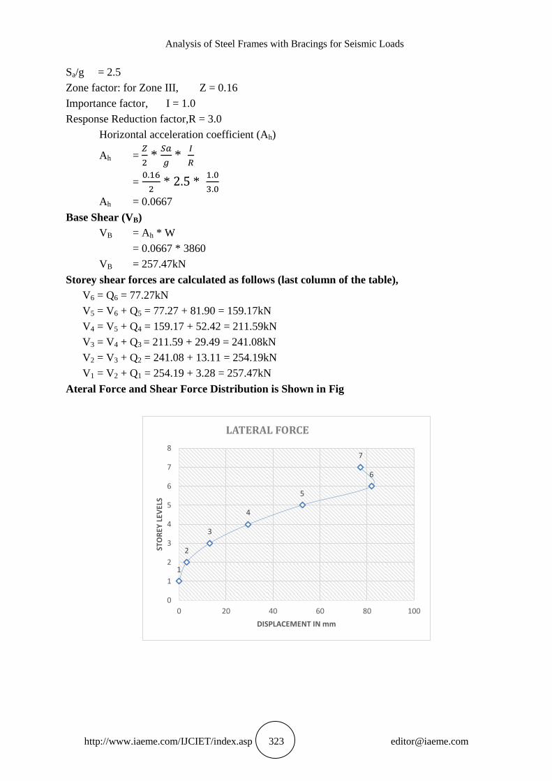
Storey shear forces are calculated as follows (last column of the table),
V6 = Q6 = 77.27kN
V5 = V6 + Q5 = 77.27 + 81.90 = 159.17kN
V4 = V5 + Q4 = 159.17 + 52.42 = 211.59kN
V3 = V4 + Q3 = 211.59 + 29.49 = 241.08kN
V2 = V3 + Q2 = 241.08 + 13.11 = 254.19kN
V1 = V2 + Q1 = 254.19 + 3.28 = 257.47kN
Ateral Force and Shear Force Distribution is Shown in Fig
1
2
3
4
5
6
7
0
1
2
3
4
5
6
7
8
0 20 40 60 80 100
STO
REY
LEV
ELS
DISPLACEMENT IN mm
LATERAL FORCE

Shaik Mohammad, N. Raja Nikhil Reddy, Ch. Saipraveen, Vankayalapati Raghu
http://www.iaeme.com/IJCIET/index.asp 324 [email protected]
Lateral Force and Shear Force Distribution
6. PRELIMINARY DIMENSIONS
Base Shear in X Direction by ESA and RSA for Different Buildings
Base Shear in Y Direction by ESA and RSA for Different Buildings
Time in X Direction by ESA and RSA for Different Models
Type of Models
Equivalent Lateral
Force Analysis in X-
direction
Response Spectrum
Analysis in X-direction
Time Period(s) Time Period (s)
Bare Frame 0.647 1.19
Frame with Knee Bracing 0.647 0.321
Time Period in Y Direction by ESA and RSA for Different Models
Type of Models
Equivalent Lateral
Force Analysis in Y-
direction
Response Spectrum
Analysis in Y-direction
Time Period (s) Time Period (s)
Bare Frame 0.647 1.4
Frame with Knee
Bracing
0.647 0.38
FLOOR LEVEL Wi (kN) hi (m) Wihi2
(kN-m2)
Storey forces
Qi = VB
∑
Storey shear
force (vi)
(kN)
6 380 18 123,120 77.27 77.27
5 580 15 130,500 81.90 159.17
4 580 12 83,520 52.42 211.59
3 580 9 46,980 29.49 241.08
2 580 6 20,880 13.11 254.19
1 580 3 5,220 3.28 257.47
∑
= 410,220
Type of Models
Equivalent Lateral Force
Analysis in X-direction
Response Spectrum
Analysis in X-direction
Base Shear (KN) Base Shear (KN)
Bare Frame 193.635 86.5
Frame with Knee Bracing 219.813 216.265
Type of Models
Equivalent Lateral
Force Analysis in Y-
direction
Response Spectrum
Analysis in Y-direction
Base Shear (KN) Base Shear (KN)
Bare Frame 193.635 71.91
Frame with Knee
Bracing
219.813 238.055
Analysis of Steel Frames with Bracings for Seismic Loads
http://www.iaeme.com/IJCIET/index.asp 325 [email protected]
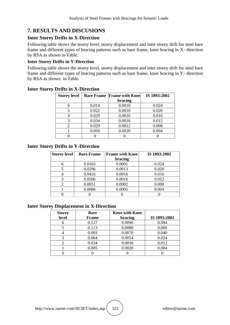
7. RESULTS AND DISCUSIONS
Inter Storey Drifts in X-Direction
Following table shows the storey level, storey displacement and inter storey drift for steel bare
frame and different types of bracing patterns such as bare frame, knee bracing in X- direction
by RSA as shown in Table.
Inter Storey Drifts in Y-Direction
Following table shows the storey level, storey displacement and inter storey drift for steel bare
frame and different types of bracing patterns such as bare frame, knee bracing in Y- direction
by RSA as shown in Table.
Inter Storey Drifts in X-Direction
Storey level Bare Frame Frame with Knee
bracing
IS 1893:2002
6 0.014 0.0010 0.024
5 0.022 0.0010 0.020
4 0.029 0.0016 0.016
3 0.034 0.0016 0.012
2 0.029 0.0012 0.008
1 0.050 0.0020 0.004
0 0 0 0
Inter Storey Drifts in Y-Direction
Inter Storey Displacement in X-Direction
Storey
level
Bare
Frame
Knee with Knee
bracing
IS 1893:2002
6 0.127 0.0090 0.084
5 0.113 0.0080 0.060
4 0.093 0.0070 0.040
3 0.064 0.0054 0.024
2 0.034 0.0036 0.012
1 0.005 0.0020 0.004
0 0 0 0
Storey level Bare Frame Frame with Knee
bracing
IS 1893:2002
6 0.0163 0.0001 0.024
5 0.0296 0.0013 0.020
4 0.0416 0.0016 0.016
3 0.0506 0.0016 0.012
2 0.0051 0.0002 0.008
1 0.0086 0.0005 0.004
0 0 0 0
Shaik Mohammad, N. Raja Nikhil Reddy, Ch. Saipraveen, Vankayalapati Raghu
http://www.iaeme.com/IJCIET/index.asp 326 [email protected]
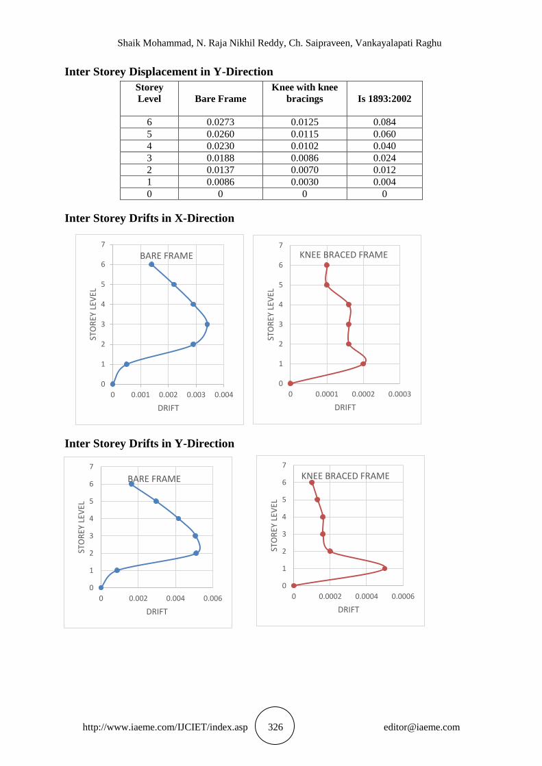
Inter Storey Displacement in Y-Direction
Storey
Level
Bare Frame
Knee with knee
bracings
Is 1893:2002
6 0.0273 0.0125 0.084
5 0.0260 0.0115 0.060
4 0.0230 0.0102 0.040
3 0.0188 0.0086 0.024
2 0.0137 0.0070 0.012
1 0.0086 0.0030 0.004
0 0 0 0
Inter Storey Drifts in X-Direction
Inter Storey Drifts in Y-Direction
0
1
2
3
4
5
6
7
0 0.0001 0.0002 0.0003
STO
REY
LEV
EL
DRIFT
KNEE BRACED FRAME
0
1
2
3
4
5
6
7
0 0.0002 0.0004 0.0006
STO
REY
LEV
EL
DRIFT
KNEE BRACED FRAME
0
1
2
3
4
5
6
7
0 0.002 0.004 0.006
STO
REY
LEV
EL
DRIFT
BARE FRAME
0
1
2
3
4
5
6
7
0 0.001 0.002 0.003 0.004
STO
REY
LEV
EL
DRIFT
BARE FRAME

Analysis of Steel Frames with Bracings for Seismic Loads
http://www.iaeme.com/IJCIET/index.asp 327 [email protected]
Inter Storey Displacement in X-Direction
Inter Storey Displacement in Y-Direction
8. SUMMARY
The model of G+5 storey building was analyzed by equivalent static and Response Spectrum
analysis. The bare frame and knee braced frame are analyzed in order to check out the
permissible storey drift as per IS 1893:2002 (part 1). The model of base length 9m and width
9m for typical storey height of 3m of each storey in building. The joints between beams and
columns are assumed as fixed. The column at ground level is fixed support with zero
orientation and displacement. The Beam ISLB200, Column ISHB 250-2 and Bracings
ISMB175. As the equivalent static analysis is done by manually for base shear and lateral
displacement. The software used in this project was ETABS, the first modelled and then
pushover analysis and response spectrum analysis has done. Therefore, the output of their
storey drift, and storey displacement are plotted either of bare frame and knee braced frame.
0
0.005
0.01
0.015
0.02
0.025
0.03
0 2 4 6 8
DIS
PLA
CEM
ENT
STOREY BARE KNEE
0
0.002
0.004
0.006
0.008
0.01
0.012
0.014
0 2 4 6 8
DIS
PLA
CEM
ENT
STOREY bare knee

Shaik Mohammad, N. Raja Nikhil Reddy, Ch. Saipraveen, Vankayalapati Raghu
http://www.iaeme.com/IJCIET/index.asp 328 [email protected]
9. CONCLUSIONS
From the above experimental study, the following conclusions were made
The seismic behavior on G+5 structural model with different bracing arrangements for
investigation.
The internal storey drift in X-direction is far compared to permissible drift ratio as per IS
1893:2002 (part 1).
Hence the knee braced frame system is significant to reduce the effect on lateral displacement
by spectral acceleration (Sa).
The internal storey drift in Y-direction is far compared to permissible drift ratio as per IS
1893:2002 (part-1).
Therefore, the knee bracing frame structural internal storey drift is acceptable by IS 1893:2002
(part 1).
FUTURE SCOPE OF WORK
The present study was conducted to find out comparison between seismic parameters such as
base shear, roof displacement, time period, storey drift, storey displacement for steel bare
frame with knee braced patterns are studied.
In this study moment resisting steel bare frame with knee bracing patterns are analyzed using
pushover analysis, equivalent static analysis, response spectrum analysis.
ACKNOWLEDGEMENTS
Thanks to the EL SHADDAI for giving this life for me as YOU praising as holy holy holy by
the Cherubim and Seraphim.
I express my grateful for my project guide Mr. Ch. Saipraveen Assistant Professor,
Department of civil Engineering, Pace Institute of Technology and sciences, Ongole. For
giving his valuable suggestions and time you spend with me for speeding up my project and
completing on time.
I thankful to my senior professor Ch. Vankayalapati Raghu Assistant Professor,
Department of civil Engineering, Pace Institute of Technology and sciences, Ongole. For your
inspirational and encouragement in the process of doing my thesis successfully.
I also express my sincere thanks to G. Ganesh Naidu Associate Professor, Head of
Department, Department of civil Engineering, Pace Institute of Technology and sciences,
Ongole. For accepting my project topic for the continuation of my project to complete it
successfully.
Last and the most of all, I offer a special word of thanks to my beloved parents and friends
who have encouraged me with good spirit. Which helped me on completing my work
successfully.
REFERENCES
[1] Mr. Choudhari V.A. CE Department of S.B.Patil College of Engineering, Indupur,
Maharashtra, India. International journal of innovations in engineering research and
technology [ijiert] issues no.: 2394-3696 volume 2, issue 6, june-2015.
[2] Arathi Thamarakshan, Arunima, Scholar, Dept. of Civil Engineering, SVNCE. “Analysis
of knee braced frame with different bracing configurations using ansys”. International

Analysis of Steel Frames with Bracings for Seismic Loads
http://www.iaeme.com/IJCIET/index.asp 329 [email protected]
Research Journal of Engineering and Technology (IRJET). e-ISSN: 2395 -0056. Volume:
04 Issue: 04. Apr -2017 www.irjet.net.
[3] Ratnesh Kumar, Prof. K. C. Biswal. “Seismic analysis of braced steel frames”. National
Institute Of Technology Rourkela Orissa, India. May 2014.
[4] Anitha M, Divya K.K, “Comparative Study On Seismic Behavior Of Steel Knee Braced
Frame With Eccentric Braced Frame”. IOSR Journal of Mechanical and Civil Engineering
e-ISSN: 2278-1684,p-ISSN: 2320-334X, PP 01-07.
[5] D. Kawai, Osaka Institute of Technology, Osaka, Japan, K. Suita Kyoto University , Y.
Koetaka &, Tokyo, Japan, K. Inoue General Building Research Corporation of Japan
(RCJ), Osaka, Japan, N. Uno & Y. Fukuchi Nippon Steel & Sumaiken Metal Products
Corporation, Ltd., Tokyo, Japan. “Mechanical behavior and design method of weld-free
steel structure with knee brace damper using square tube column”. 2012.
[6] Leelataviwat, S. & Doung, P. CE Department, King Mongkut’s University of Technology
Thonburi, Thailand. “Ductile Knee-Braced Frames for Seismic Applications”.
International Conference on Earthquake engineering and Structural Dynamics. June-2017.
[7] Viswanath.K.G, Prakash K.B, Anant Desai, Director/Principal, Ashokrao Mane Group of
Institutions, Vathar Tarf Vadgaon, Kolhapur.Seismic Analysis of Steel Braced Reinforced
Concrete Frames”.
[8] HUANG Zhen, LI Qing-song, CHEN Long-zhu, (2005), “Elastoplastic analysis of knee
bracing frame,” Journal of Zhejiang University Science.
[9] MehrdadLotfollahi, MassoodMofid (2006), “On the design of new ductile knee bracing,
Journal of Constructional Steel Research 62, pp 282–294
[10] Mahmoud Miri, Abdolreza Zare, Hossein Abbas zadeh,(2009),“Seismic behavior of steel
frames investigation with knee brace based on pushover analysis,” World Academy of
Science, Engineering and Technology 50
[11] Mina Naeemi, Majid Bozorg,(2009),“Seismic performance of knee braced frame,” World
Academy of Science, Engineering and Technology 50.