analysis of pipe-roof in tunnel exiting portal by the...
TRANSCRIPT

Research ArticleAnalysis of Pipe-Roof in Tunnel Exiting Portal bythe Foundation Elastic Model
Yanbin Luo1 Jianxun Chen1 Bao Liu2 Lijun Chen1 and Jiangtao Xie1
1School of Highway Changrsquoan University Middle-Section of Nanrsquoer Huan Road Xirsquoan Shaanxi Province China2China Construction Seventh Engineering Division Corp Ltd Zhongjian Building Chengdong Road No 108Zhengzhou Henan China
Correspondence should be addressed to Jianxun Chen chenjx1969163com and Lijun Chen chenlijun2004126com
Received 21 April 2017 Revised 1 August 2017 Accepted 17 August 2017 Published 18 October 2017
Academic Editor Francesco Marotti de Sciarra
Copyright copy 2017 Yanbin Luo et al This is an open access article distributed under the Creative Commons Attribution Licensewhich permits unrestricted use distribution and reproduction in any medium provided the original work is properly cited
The Pasternak double-parameter elastic foundation model of pipe-roof during the construction of tunnel exits is first establishedBased on the portal project of Hanjiashan highway tunnel an inclinometer is adopted to measure the settlement deformation of apipe-roof and demonstrates the deformation law in tunnel exiting portals The formulas for calculating the deflection and internalforces are derived to analyze the deformation of the pipe-roof in each excavation stage and the results are compared with fieldmonitoring data Finally the influences of excavation height excavation footage and stiffness of the pipe-roof on the support effectare investigated Analysis indicates that the longitudinal settlement curve shows a groove distribution which can be divided intofive stages micro rapid continuous resilience and stable deformation Moreover the subsidence rate reaches its maximum at thetunnel faceThe influence of tunnel excavation on the deformation mainly has a range of 15 times the excavation height To controlthe deflection of the pipe-roof excavation height should be controlled in the range of 35m excavation footage should be controlledin the range of 1ndash14m and the diameter and thickness of the selected pipe-roof should be in the ranges of 89ndash159mm and 5ndash8mmrespectively
1 Introduction
The rock mass of a tunnel portal is often broken looseand weathering and has generally poor geological conditionsPortal excavation can destroy the original balance of a moun-tain thus easily generating bedding slipping collapse and soon [1ndash3] Adopting pipe-roofs is an effective measure exten-sively applied to overcome the poor stability and slope slidingof heading [4ndash7] Many scholars have conducted extensiveresearch on the support mechanism of pipe-roofs includinganalytical studies [8ndash11] field tests [8 12ndash14] numericalsimulations [15ndash18] andmodel tests [19ndash22] Existing work ismainly aimed at studying the mechanical behaviors of pipe-roofs in tunnel entry portals Pipe-roofs are adopted not onlyin tunnel entry portals but also in tunnel exiting portalswhich have unsatisfactory conditions of eluvium coveringand landsides and are adjacent to bridges The differencein boundary conditions between tunnel entrances and exits
leads to differences in the mechanical behaviors of pipe-roofs Therefore it is necessary to take further research onthe effects andmechanical behaviors of pipe-roofs during theconstruction of tunnel exits
In this paper the Pasternak double-parameter elasticfoundation model of pipe-roof during the construction oftunnel exits is first established and then with the HanjiashanTunnel of Tongxun Highway as basis the inclinometer isfirst adopted to measure the deformation of the pipe-roofin the tunnel exiting portal and the deformation law ofthe pipe-roof is obtained Deformation of the pipe-roof ineach excavation stage is analyzed and compared with fieldmonitoring data The accuracy of the calculated model andthe theoretical derivation is verified Finally the supporteffect of the pipe-roof in different tunnel excavation heightsexcavation footages and pipe stiffness is investigated Theresults can provide a basis for selecting reasonable parametersof pipe-roofs in tunnel exiting portals
HindawiMathematical Problems in EngineeringVolume 2017 Article ID 9387628 12 pageshttpsdoiorg10115520179387628
2 Mathematical Problems in Engineering
Excavated Excavatedunsupported
sectionsupported
sectionUnexcavated section
Guiding wall Pipe-roof Primary support
Excavation direction Steel frame
TunnelfaceFracture plane
AB
y
O
ℎ
d1d2 q(x)
x
CD
45∘ minus 2
Figure 1 Force of pipe-roof in the process of tunnel construction at the exit portal section
2 Mechanical Analysis ofthe Pipe-Roof Deformation
21 Building the Analytical Model The self-bearing capacityof the rock mass is poor when the tunnel construction is inshallow buried strata The force of the pipe-roof is definiteand the action between the upper soil and the pipe-roof is notconsidered It assumes that the pipe-roof is the straight beamacting on the Pasternak elastic foundation and the uniformload 119902(119909) of the covering soil acts on the pipe-roof in theexcavation section [23] Owing to the deformation of the rockmass which begins with the range in front of the tunnel facethe maximum relaxation range of the rock mass is within therange of the fracture plane in front of the tunnel face
According to the theory of rock mass pressure the actingrange of the longitudinal load of the pipe-roof in front of thetunnel face is ℎ sdot (tan 45∘ minus 1205932) Considering the state of thepipe-roof and the rock mass during excavation the pipe-roofcan be divided into four segments in the excavation cycle asshown in Figure 1 (1)The support section (119874119860) this sectioncan be assumed as an elastic fixed endwith an initial displace-ment 1199100 and an initial angle 1205790 The initial displacement 1199100 ofthe pipe-roof can be valued as the measured settlement of thecrown (2)The section (119860119861) without support the pipe-roofcompletely bears the pressure 119902(119909) of the upper rockmass (3)The section (119861119862) in the disturbance the pipe-roof is affectednot only by the rock mass pressure of 119902(119909) but also by thesubgrade reaction 119901(119909) (4) Undisturbed section (119862119863) thissection only bears the subgrade reaction 119901(119909) between thepipe-roof and the rock mass
The subgrade reaction can be calculated using the double-parameter Pasternak model Based on elastic foundationbeam theory the subgrade reaction and the deflection differ-ential equation of the pipe-roof can be deduced as follows
119901 (119909) = 119896119910 minus 119866119901 11988921199101198891199092 (1a)
1198641198681198891199104 (119909)1198891199094 minus 119866119901119887lowast 1198891199102 (119909)1198891199092 + 119896119887lowast119910 (119909) = 119887119902 (119909) (1b)
In the equation 119864 is the elastic modulus 119866119901 is the shearmodulus of the foundation 119868 is the inertia moment of the
pipe-roof 119887lowast is the equivalent width of the beam consideringthe foundation continuity 119887lowast = 119887[1 + (119866119901119896)12119887] 119887 is thewidth of the elastic foundation beam (which is equal to thediagram of the pipe-roof) 119896 is the coefficient of the subgradereaction and 119910(119909) is the deflection of the pipe-roof
The elastic foundation beam model of the pipe-roof isdivided into two types [24] based on the position of the tunnelface and the pipe-roof (1) When the tunnel face is far awayfrom the front end of the pipe-roof the affected area of tunnelexcavation does not reach the front end of the pipe-roofwhich is considered an infinite elastic foundation beam asshown in Figure 2(a) (2) When the tunnel face is close to thefront end of the pipe-roof the affected area of tunnel excava-tion reaches the front end of the pipe-roof which is consid-ered a finite elastic foundation beam as shown in Figure 2(b)
In contrast to tunnel exit guiding wall is installed in thesame tunnel entrance and pipe-roof is guided through thereserved hole in the guidingwall but the excavation directionis converse The pipe-roofs in tunnel exit and entrance havethe same effort in protecting the safety of the tunnel portalconstruction but the displayed mechanic effort of them isdifferent At tunnel exit the tunnel face starts from inside tooutside of the tunnel the far end of pipe-roof is restrainedby the guiding wall and the corresponding constrainedcondition at the far end of pipe-roof can be idealized as afixed support as shown at the point119862 in Figure 2(b) At tunnelentrance the tunnel face starts from outside to inside of thetunnel and the constrained condition at the point119862 is usuallyidealized as a hinged support [23]
In addition it is worth mentioning that the abovecompared analysis of tunnel exit and entrance have the sameprecondition of which the guiding wall is made first and thepipe-roof is constructed from the outside to inside in thetunnel portal In some instances the pipe-roof is constructedfrom the inside to outside and the guiding wall does not needto be set In this situation the tunnel exit will bemore danger-ous than the tunnel entrance However this situation is onlysuitable for the good geological conditions in tunnel portaland is very dangerous for the poor geological conditions Inpractice the pipe-roof is usually constructed after finishingthe guiding wall in the tunnel portal with weak rock massand is guided by the reserved hole in the guiding wall This
Mathematical Problems in Engineering 3
45∘ minus 2
AB
y
d1
d3
d2
q(x)
xC
D
y0
p(x)0
(a) Model A
45∘ minus 2
AB
y
d1
q(x)
xC y0
d3 le d2
p(x)
0
(b) Model B
Figure 2 Mechanical model of pipe-roof in the process of tunnel construction at the exit portal section
situation exists in theory and will not be considered in thispaper
22 Solution of Deflection Differential Equation Accordingto the mechanical calculation model of the pipe-roof thedeflection differential equation in the sections of the pipe-roof and the corresponding solutions can be calculateddepending on elastic foundation beam theory
221 Model A The deflection differential equations in thesections of the pipe-roof are as follows
(1) Section 119860119861 The deflection differential equation in thesection of 119860119861 is
1198641198681198894119910 (119909)1198891199094 = 1198871199020 (2)
The corresponding solution can be expressed as1199101 (119909) = 11986211199093 + 11986221199092 + 1198623119909 + 1198624 + 1199101lowast (3)
1199101lowast (119909) = 1199020241198641198681199094 (4)
1198621 1198622 1198623 and 1198624 are the undetermined coefficients
(2) Section 119861119862 The deflection differential equation in thesection of BC is
1198641198681198894119910 (119909)1198891199094 minus 119866119901119887lowast 1198892119910 (119909)1198891199092 + 119896119910 (119909) 119887lowast = 1198871199020 (5)
The corresponding solution can be expressed as1199102 (119909)= 119890120572119909 (1198625 cos120573119909 + 1198626 sin120573119909)+ 119890minus120572119909 (1198627 cos120573119909 + 1198628 sin120573119909) + 1199102lowast(6)
119910lowast2 (119909)= 119902119896119887lowast [1 minus cosh120573 (119909 minus 1198891 minus 1198892) cos120573 (119909 minus 1198891 minus 1198892)] (7)119862511986261198627 and1198628 are the undetermined coefficients 1205824 =119896119887(4119864119868) 120572 = 120582radic1 + 1198661199011205822119896 120573 = 120582radic1 minus 1198661199011205822119896
(3) Section 119862119863 The deflection differential equation in thesection of 119861119862 is
1198641198681198894119910 (119909)1198891199094 minus 119866119901119887lowast 1198892119910 (119909)1198891199092 + 119896119910 (119909) 119887lowast = 0 (8)
The corresponding solution can be expressed as
1199103 (119909) = 119890120572119909 (1198625 cos120573119909 + 1198626 sin120573119909)+ 119890minus120572119909 (1198627 cos120573119909 + 1198628 sin120573119909) (9)
Accordingly the boundary conditions of model A are asfollows 11991011003816100381610038161003816119909=0 = 119910012057911003816100381610038161003816119909=0 = 119910(1)1 10038161003816100381610038161003816119909=0 = 120579011991011003816100381610038161003816119909=119889
1
= 11991021003816100381610038161003816119909=1198891
119910(2)1 10038161003816100381610038161003816119909=119889
1
= 119910(2)2 10038161003816100381610038161003816119909=1198891
119910(1)1 10038161003816100381610038161003816119909=119889
1
= 119910(1)2 10038161003816100381610038161003816119909=1198891
119910(3)1 10038161003816100381610038161003816119909=119889
1
= 119910(3)2 10038161003816100381610038161003816119909=1198891
11991031003816100381610038161003816119909rarrinfin = 012057931003816100381610038161003816119909rarrinfin = 0
(10)
The calculation result is1198625 = 1198626 = 0 When formulas (3)(6) (7) and (9) and the boundary conditions are used thefollowing coefficient matrix can be obtained
((((((
0 0 0 1 0 00 0 1 0 0 011988931 11988921 1198891 1 11987535 11987536311988921 21198891 1 0 11987545 1198754661198891 2 0 0 11987555 119875566 0 0 0 11987565 11987566
))))))
119862111986221198623119862411986271198628
=
119910012057901205953120595412059551205956
(11)
4 Mathematical Problems in Engineering
In this matrix
11987535 = minus119890minus1205721198891 cos (120573119889) 11987536 = minus119890minus1205721198891 sin (120573119889) 11987545 = 119890minus1205721198891 [120572 cos (120573119889) + 120573 sin (120573119889)] 11987546 = 119890minus1205721198891 [120572 sin (120573119889) minus 120573 cos (120573119889)] 11987555 = 119890minus1205721198891 [minus2120572120573 sin (120573119889) minus (1205722 minus 1205732) cos (120573119889)] 11987556 = 119890minus1205721198891 [2120572120573 cos (120573119889) minus (1205722 minus 1205732) sin (120573119889)] 11987565 = 119890minus1205721198891 [minus (1205733 minus 31205722120573) sin (120573119889)+ (1205723 minus 31205721205732) cos (120573119889)] 11987566 = 119890minus1205721198891 [(1205733 minus 31205722120573) cos (120573119889)+ (1205723 minus 31205721205732) sin (120573119889)] 1205953 = minus 1199021198894124119864119868 + 119902119896119887lowast [1 minus cos (1205731198892) cosh (1205731198892)] 1205954 = minus119902119889316119864119868 + 120573 119902119896119887lowast [cos (1205731198892) sinh (1205731198892)minus cosh (1205731198892) sin (1205731198892)] 1205955 = minus119902119889212119864119868 + 21205732 119902119896119887lowast sin (1205731198892) sinh (1205731198892) 1205956 = minus1199021198891119864119868 minus 21205733 119902119896119887lowast [cosh (1205731198892) sin (1205731198892)+ cos (1205731198892) sinh (1205731198892)]
(12)
After the preceding process to calculate the undeterminedcoefficients 1198621ndash1198628 of the deflection equation the result isintroduced in formulas (3) (6) and (9) and the deflectionexpression of the pipe-roof sections in model A is deter-mined The moment shear force and rotation angle of thepipe-roof can be obtained based on Bernoulli-Euler theoryThe equation is as follows
119872(119909) = minus11986411986812059721199101205971199092 119873 (119909) = 119889119872119889119909 = minus11986411986812059731199101205971199093 120579 (119909) = 119889119910119889119909
(13)
222 Model B The deflection differential equation of sec-tions119860119861 and119862119863 in model B is similar to the one in model ATherefore the solution of the differential equation consists offormulas (3) and (6)
The boundary conditions of model B are as follows
11991011003816100381610038161003816119909=0 = 119910012057911003816100381610038161003816119909=0 = 119910(1)1 10038161003816100381610038161003816119909=0 = 120579011991011003816100381610038161003816119909=1198891
= 11991021003816100381610038161003816119909=1198891
119910(1)1 10038161003816100381610038161003816119909=119889
1
= 119910(1)2 10038161003816100381610038161003816119909=1198891
119910(2)1 10038161003816100381610038161003816119909=119889
1
= 119910(2)2 10038161003816100381610038161003816119909=1198891
119910(3)1 10038161003816100381610038161003816119909=119889
1
= 119910(3)2 10038161003816100381610038161003816119909=1198891
11991021003816100381610038161003816119909=119889
1+119889
2
= 0119910(1)2 10038161003816100381610038161003816119909=119889
1+119889
2
= 12057921003816100381610038161003816119909=1198891+119889
2
= 0
(14)
With formulas (3) and (6) and the boundary conditionsthe following coefficient matrix can be obtained
((((((((((((
0 0 0 1 0 0 0 00 0 1 0 0 0 0 011988931 11988921 1198891 1 11987535 11987536 11987537 11987538311988921 21198891 1 0 11987545 11987546 11987547 1198754861198891 2 0 0 11987555 11987556 11987557 119875586 0 0 0 11987565 11987566 11987567 119875680 0 0 0 11987575 11987576 11987577 119875780 0 0 0 11987585 11987586 11987587 11987588
))))))))))))
((((((((((((
11986211198622119862311986241198625119862611986271198628
))))))))))))
=((((((((((((
11991001205790120595312059541205955120595600
))))))))))))
(15)
In this matrix
11987535 = minus1198901205721198891 cos (1205731198891) 11987536 = minus1198901205721198891 sin (1205731198891) 11987537 = minus119890minus1205721198891 cos (1205731198891) 11987538 = minus119890minus1205721198891 sin (1205731198891) 11987545 = 1198901205721198891 [120573 sin (1205731198891) minus 120572 cos (1205731198891)] 11987546 = minus1198901205721198891 [120572 sin (1205731198891) + 120573 cos (1205731198891)]
Mathematical Problems in Engineering 5
11987547 = 119890minus1205721198891 [120572 cos (1205731198891) + 120573 sin (1205731198891)] 11987548 = 119890minus1205721198891 [120572 sin (1205731198891) minus 120573 cos (1205731198891)] 11987555 = 1198901205721198891 [2120572120573 sin (1205731198891) + (1205732 minus 1205722) cos (1205731198891)] 11987556 = 1198901205721198891 [(1205732 minus 1205722) sin (1205731198891) minus 2120572120573 cos (1205731198891)] 11987557 = 119890minus1205721198891 [minus2120572120573 sin (1205731198891) + (1205732 minus 1205722) cos (1205731198891)] 11987558 = 119890minus1205721198891 [(1205732 minus 1205722) sin (1205731198891) + 2120572120573 cos (1205731198891)] 11987565 = 1198901205721198891 [(minus1205733 + 31205722120573) sin (1205731198891)+ (31205721205732 minus 1205723) cos (1205731198891)] 11987566 = 1198901205721198891 [(1205733 minus 31205722120573) cos (1205731198891)+ (31205721205732 minus 1205723) sin (1205731198891)] 11987567 = 119890minus1205721198891 [(minus1205733 + 31205722120573) sin (1205731198891)+ (1205723 minus 31205721205732) cos (1205731198891)] 11987568 = 119890minus1205721198891 [(1205733 minus 31205722120573) cos (1205731198891)+ (1205723 minus 31205721205732) sin (1205731198891)] 11987575 = 119890120572(1198891+1198892) cos [120573 (1198891 + 1198892)] 11987576 = 119890120572(1198891+1198892) sin [120573 (1198891 + 1198892)] 11987577 = 119890minus120572(1198891+1198892) cos [120573 (1198891 + 1198892)] 11987578 = 119890minus120572(1198891+1198892) sin [120573 (1198891 + 1198892)] 11987585 = 119890120572(1198891+1198892) 120572 cos [120573 (1198891 + 1198892)]minus 120573 sin [120573 (1198891 + 1198892)] 11987586 = 119890120572(1198891+1198892) 120572 sin120573 [120573 (1198891 + 1198892)]+ 120573 cos [120573 (1198891 + 1198892)] 11987587 = 119890minus120572(1198891+1198892) minus120572 cos [120573 (1198891 + 1198892)]minus 120573 sin [120573 (1198891 + 1198892)] 11987588 = 119890minus120572(1198891+1198892) minus120572 sin [120573 (1198891 + 1198892)]+ 120573 cos120573 [120573 (1198891 + 1198892)] 1205953 = minus 1199021198894124119864119868 + 119902119896119887lowast [1 minus cos (1205731198892) cosh (1205731198892)] 1205954 = minus119902119889316119864119868 + 120573 119902119896119887lowast [sinh (1205731198892) cos (1205731198892)minus cosh (1205731198892) sin (1205731198892)]
1205955 = minus119902119889212119864119868 + 21205732 119902119896119887lowast sinh (1205731198892) sin (1205731198892) 1205956 = minus1199021198891119864119868 minus 21205733 119902119896119887lowast [cosh (1205731198892) sin (1205731198892)+ sinh (1205731198892) cos (1205731198892)]
(16)
After the preceding process to calculate the undeterminedcoefficients 1198621ndash1198628 of the deflection equation the resultis introduced in formulas (3) and (6) and the deflectionexpression of the pipe-roof sections inmodel B is determinedThen themoment shear force and rotation angle of the pipe-roof can be obtained
3 Engineering Case Analysis
31 General Situation of Construction Hanjiashan tunnel ofthe TongchuanndashXunyi expressway is located in the northwestof Tuqiao Yaoshang village in Xunyi county extending fromthe northeast to the southeast The tunnel has a design speedof 80 kmh and is bidirectional in four lanes The left lineis 885m with a maximum buried depth of 123m and theright line is 865m with a maximum buried depth of 142mThe entrance and exit of the tunnel are located in the slopezone the exit in particular lies on a steep terrain The slopeof the left exit reaches 25∘ndash40∘ andmainly comprises residualsilty clay fully weathered sandstone conglomerate andmud-stoneThe entrance and exit of the tunnel easily collapse withthe occurrence of strong rainfall or construction disturbance
Road construction was difficult because of the geologicaland topographic conditions of the tunnel exit In addition thetunnel exit is adjacent to the bridge making it inconvenientto adopt big machines and equipment Therefore a one-way construction plan was adopted wherein the tunnel wasexcavated to transfixion from a substantial pile number toa small one The advanced pipe-roof was to be constructedstarting from the inside to outside In thisway the topographyobstacle of the tunnel exit was overcome while avoidingdestruction of the ecological environment caused by theroad construction in a steep slope However compared withthe entrance project the pipe-roof method employed in thetunnel exiting portal was more conducive for maintaining asafe and steady slope The original design was also optimizedto ensure construction progress and safety The specificsupport parameters are shown in Figure 3 In order toensure construction safety during the tunnel exit the threebenches and seven steps excavationmethodwas adoptedTheexcavation span is 1278mand the excavation height is 928mThe excavation footage is 05m which is in accord with thelongitudinal space of steel frame
32 Field Measurement of the Pipe-Roof
321 Measurement Arrangement The tunnel exit was chosenas the test section for measuring the deformation of thepipe-roof in the tunnel exiting portal because of its poortopographic conditions A CX-4C inclinometer was usedto measure the deformation of the pipe-roof in the tunnel
6 Mathematical Problems in Engineering
50 mG times 4 mm leading ductuleCircumferential interval 40 cmL = 450 cm
222 mm early strengthMortar feet-lock bolts
L = 350 cm 8 mG times 20 cG times 20 cmMesh reinforcement
= 50 cmI20a steel
Yas semicircumference drainpipe50 cm C30 reinforced concrete lining12 mm EVAECB waterproof board26 cm C20 shotcrete350 gG2 geotextile
(a) Transversal lining design
Open-cuttunnel lining
127 mG times 45 mm steel pipe 40 mmL = 3000 cm = 2∘
55 cm model building concrete arch
C15 concrete foundation(b) Transversal pipe-roof design
Figure 3 Design of tunnel exiting portal
exiting portalThis inclinometer has high precision good sta-bility high repeatability and small drift It is also convenientto operate and its monitoring data are reliable
An inclinometer was buried in the crown of the number16 and number 6 holes of the pipe-roof The effective mea-surement range of each inclinometer is 20m The settlementdatum was set in each orifice of the inclinometer measuringone point per 05m The longitudinal and lateral arrange-ments of the inclinometer tube are shown in Figures 4 and 5
The inclinometer was buried after pipe-roof installationand before grouting The burying steps were as follows (1)The pole was cleaned to put the inclinometer in the pipes(2) The inclinometer was placed in the pipes by using aplumb to control the direction and vertically adjusting aset of guide The grouting tube and the inclinometer wereput together to successfully put the grouting tube in thepipes While connecting the inclinometers muck should beavoided from blocking the guide The pipes were fixed usingscrews and gluing them down to prevent the slurry fromblocking the inclinometer and the guide (3) The orifice was
temporarily sealed and the pipe ends were warped using wetgeotextile to avoid burning the inclinometer while weldingThe guide tube was extended to ensure the precise positionof the inclinometer orifice and for easy sealing (4) The pipe-roof was grouted (5) The guide tube was cut off after theinitial setting while ensuring that the inclinometer was notdamaged The inclinometer end was smoothened
The initial value should usually be measured twice orthree times with the steady one chosen as the referencevalue The coordinate of the inclinometer orifice is taken asthe datum When every measurement was carried out theinstrument probe was put in the inclinometer with a PVCtube measuring one point per 05m to the bottom of thehole The difference of the measured value subtracted fromthe initial one was the measured displacement Δ119884 = 119884119898 minus 119884119894322 Analysis of Measured Results The measurement lastedfrom January 2015 toMarch 2015 Two holes were arranged tomeasure the deformation of the pipe-roof on the basis of theplan As the number 6 hole was damaged only themeasuring
Mathematical Problems in Engineering 7
127 mm pipe-roofPipe-roof
Excavation direction
Guiding wall
Inclinometer
Tunnel face
A
A25 mm PE grouting pipe M30 cement mortar
70 mm inclinometer
Figure 4 The longitudinal arrangement of inclinometer tube
127 mG times 45 mm steel pipe 40 mmL = 3000 cm = 2∘
Number 16 pipe-roof
Number 6 pipe-roof
Figure 5 The lateral arrangement of inclinometer tube
data of the number 16 hole was analyzed for regular changeThe specific measured results and analyses are as in Figures6ndash8
Figure 6 shows that the settlement of the pipe-roofincreases along with the excavation First the deformationdramatically increases and then gradually stabilizes with theconstruction of the initial support The vertical displacementof the umbrella arch in the range of 1-2m of the tunnel ispositive The pipe-roof appears to trace upward in this rangeThis result shows that the umbrella plays an important role asan end constraint in the tunnel exiting portal Therefore theumbrella arch is vital for setting up the pipe-roof advancedsupport system because it stabilizes the slope and controlsthe entire settlement of the pipe-roof The cumulative curveof the pipe-roof settlement is concave where both endsare small and the middle part is large This outcome isattributed to the tunnel face moving toward the portal andthe settlement of the pipe-roof accumulating in space andtime The main reason is that on one hand one end of thepipe-roof is constrained by the umbrella arch the other endis put on the stable support and the force model of thepipe-roof is approximated as the restrained beam with twoends The measurement result shows the deformation of thetunnel initial support Meanwhile when monitoring of thedeformation of the pipe-roof began the vault settlement ofthe pipe-roof end put on the initial support was stable Onthe other hand the tunnel was excavated in the pile number
2015126201513020153112015324
201518201519
20151112015110
2015113
2015115
2015112
2015114 2015118
20151162015117
2015119
minus70
minus60
minus50
minus40
minus30
minus20
minus10
0
10
Disp
lace
men
t (m
m)
2 4 6 8 10 12 14 16 18 200
Depth (m)
Figure 6 Cumulative curve of pipe-roof settlement
of the 14m measured point when monitoring began Thisresulted in the partial displacement of the measured point at14ndash20m depth leading to the loss of measured displacementand causing the settlement of the measured point at 10ndash20mdepth to be less than the one at 0ndash10m depth
Figure 7 shows that the settlement time curve of the pipe-roof settlement can be divided into five stages (1) MicroDeformation When the tunnel face is near the measuredpoint the settlement of the pipe-roof is small (2) RapidDeformation When the upper bench is excavated the set-tlement of the pipe-roof rapidly increases the tunnel face isnear the section of the measured point and the settlementrate reaches a maximum (3) Continuous DeformationWhenthe middle bench is excavated the settlement of the pipe-roof continually increases and then slows with the initialsupport of the tunnel and the pipe-roof bearing the rockmass pressure together (4) Resilience DeformationWhen theinvert is backfilled the tunnel face passes through a length of
8 Mathematical Problems in Engineering
SettlementSettlement rate
0
10
20
30
40
50
60
70
Settl
emen
t (m
m)
settl
emen
t rat
e (m
md
)
27 39118 128 227 32918 217 319date
Figure 7 The settlement time curve of pipe-roof measuring pointat the depth of 7m
a section of the measured point and the deformation of thepipe-roof rebound emerges with micro resilience This effectis attributed to the support structure which is in a state ofelasticity with the protection of the pipe-roof Furthermorethis phenomenon shows the well-advanced support actionof the pipe-roof (5) Stable Deformation When the initialsupport encloses for a while the settlement of the pipe-rooftends to stabilized At this time the stability of the rock massis a result of the combined work of the pipe-roof and theinitial support The advanced support action of the pipe-roofis basically completed
Figure 8 shows that the ratio of the accumulated settle-ment accounting for the total settlement gradually decreaseswith the increase of depth of the inclinometer measuredpoint which is farther from the portal When the tunnel faceis close to the shallow measured point near the portal thepipe-roof appears to trace upward This is attributed to themeasured points which are close to the umbrella arch inwhich the umbrella arch plays an important role as an endconstraint The settlement of the pipe-roof in the tunnel faceis large therefore elastic deformation appears in the pipe-roofThe excavation range that influences the deformation ofthe pipe-roof in front of the tunnel face is 15 times that ofthe excavation height (2m) With the increase in measureddepth the end constraint effect of the pipe-roof graduallyweakens Meanwhile the increase in buried depth enlargesthe range in which the excavation influences the deformationof the pipe-roof in front of the tunnel face However theinfluence range is still 3m in front of the tunnel face whichis 15 times that of the excavation height
33 Model Validation According to the engineering char-acteristics of the Hanjiashan Tunnel the parameters of therock mass are as follows coefficient of the subgrade reaction119896 = 40000 kNm3 shear modulus of the foundation 119866119901 =10000 kNm bulk density = 20 kNm3 internal friction angle120593 = 22∘ single pipe combined modulus 119864119901 = 4726GPa
single pipe combined inertial moment 119868119901 = 1277times106mm4and tunnel excavation height ℎ = 2m Two steel framesare supported in each cycle with a 50 cm spacing betweenframes Therefore the excavation footage 1198891 is 12m
331 Model A When the pile of the tunnel excavation is 9maway from the orifice the vertical rock mass pressure of thepipe-roof is 119902 = 140 kPa The initial vertical displacementof the pipe-roof and the initial support connecting end 1199100 =10mmThe initial angle of the pipe-roof is 1205790 = 15∘ becausethe pipe-roof is far away from the umbrella arch The deflec-tion curves of the pipe-roof are calculated by MATLAB andcompared with the measured values as shown in Figure 9
The comparison between the calculated results and themeasured data shows the following
(1)The deflection curve of the pipe-roof is in good agree-ment with the measured one which shows the correctnessof the theoretical calculation The differences between thetheoretical calculations and the measured results are mainlyattributed to the hypothesis that the soil is a uniformlycontinuous elastomer in theoretical calculation Moreoverthe soil is anisotropic and heterogeneous in construction
(2) The range in which the excavation influences thedeformation of the pipe-roof in front of the tunnel face is 3mwhich is 15 times that of the height of the tunnel excavationand is in good agreement with the measured results
(3)The maximum deflection of the pipe-roof is 256mmwhich occurred near the tunnel face The reason is that thearea was excavated without support and thus the pipe-roofbears all the rock mass pressure and the deformation reachesthe maximum This area is also the most critical in tunnelexcavation resulting from the largest deformation
332 Model B The distance between the tunnel face and thefracture plane is almost 1198892 = ℎ sdot tan(45∘ minus 1205932) = 135min which model B is adopted when the distance between thetunnel face and the umbrella arch is less than 135m Whenthe tunnel face is 135m away from the umbrella arch thevertical uniform rock mass pressure of the pipe-roof is 119902 =50 kPa The initial vertical displacement of the pipe-roof andthe initial support connecting end is 1199100 = 10mmThe initialangle of the pipe-roof is 1205790 = 1∘ because the pipe-roof is closeto the umbrella arch The deflection curves of the pipe-roofare calculated byMATLAB and compared with themeasuredvalues as shown in Figure 10
The comparison between the calculated results and themeasured data shows the following
(1) The deflection curve of the pipe-roof is in goodagreement with the measured one which shows the accuracyof the theoretical calculation
(2) The range in which the excavation influences thedeformation of the pipe-roof in front of the tunnel face is 3m
(3) The maximum deflection of the pipe-roof is 215mmwhich occurred near the tunnel face
From the preceding analysis the deformation of the pipe-roof relates to the mechanical parameters of the rock massand the pipe-roof as well as the excavation position thefootage and the excavation height
Mathematical Problems in Engineering 9
0
10
20
30
40
50uu
0(
)
minus10 minus9 minus8 minus7 minus6 minus5 minus4 minus3 minus2 minus1 0 1minus11
Distance to tunnel face (m)
(a) At 4m depth
0
10
20
30
40
50
60
70
uu
0(
)
minus6 minus4 minus2 0 2minus8
Distance to tunnel face (m)
(b) At 6m depth
Figure 8 The settlement space curves of pipe-roof measuring point at the different depth
1 2 3 4 5 60
Longitudinal position (m)
0
5
10
15
20
25
30
Defl
ectio
n (m
)
Theoretical calculationField test
Figure 9 Comparison of calculated values and measured one ofpipe-roof deflection in model A
34 Parameters Analysis
341 ExcavationHeight Theexcavation height values are ℎ =2 25 3 35 4 and 45m The deflection curves of differentexcavation heights in model A are shown in Figure 11(a)The variation curve of the maximum deflection of differentexcavation heights is shown in Figure 11(b)
Figure 11 shows the following(1) The deflection of the pipe-roof increases with the
increase in excavation height of the tunnel face When ℎ isbetween 2 and 35m the excavation height has a slight effecton the deformation of the pipe-roof when ℎ is larger than35m the deformation of the pipe-roof sharply increases with
Theoretical calculationField test
0
5
10
15
20
25
Defl
ectio
n (m
m)
Longitudinal position (m)30252015100500
Figure 10 Comparison of calculated values and measured one ofpipe-roof deflection in model B
the increase in excavation height Therefore the excavationheight should be controlled in the range of 35m
(2) The maximum deflection of the pipe-roof appearsnear the tunnel face
(3) The range in which excavation influences the defor-mation of the pipe-roof in front of the tunnel face increaseswith the increase in excavation height and the range is 15times that of the excavation height
342 Excavation Footage The excavation footage values are1198891 = 06 08 10 12 14 and 16m The deflection curvesof different excavation footages in model A are shown in
10 Mathematical Problems in Engineering
0
10
20
30
40
50
60
Defl
ectio
n (m
m)
1 2 3 4 5 60
Longitudinal position (m)
ℎ = 2 mℎ = 25 mℎ = 3 m
ℎ = 35 mℎ = 4 mℎ = 45 m
(a) Deflection with different excavation height
Excavation height (m)302520 50454035
20
25
30
35
40
45
50
55
Defl
ectio
n (m
m)
(b) The maximum deflection with excavation height
Figure 11 Variation curve of pipe-roof deflection with tunnel excavation height
0
10
20
30
40
Defl
ectio
n (m
m)
1 2 3 4 5 60
Longitudinal position (m)
Footage 06 mFootage 08mFootage 10 m
Footage 12 mFootage 14 mFootage 16m
(a) Deflection with different excavation
15
20
25
30
35
40
Defl
ectio
n (m
m)
20151005
Excavation footage (m)
(b) The maximum deflection with excavation
Figure 12 Variation curve of pipe-roof deflection with tunnel excavation footage
Figure 12(a) The variation curve of the maximum deflectionof different excavation footages is shown in Figure 12(b)
Figure 12 shows the following(1) The deflection of the pipe-roof increases with the
increase in excavation footage of the tunnel faceThe increaserate also rises Therefore the excavation footage should becontrolled in the range of 1ndash14m
(2) The maximum deflection of the pipe-roof appearsnear the tunnel face
(3) The range in which the excavation influences thedeformation of the pipe-roof in front of the tunnel face
increases with the increase in excavation footage and therange is 15 times that of the excavation height
343 Pipe Diameter According to the common size of thepipe-roof (as shown in Table 1) the deflection curves of thedifferent pipe diameters in model A are shown in Figure13(a) The variation curve of the maximum deflection of thedifferent pipe diameters is shown in Figure 13(b)
Figure 13 shows the following(1) When the pipe diameter is less than 108mm the
deflection of the pipe-roof significantly increases with the
Mathematical Problems in Engineering 11
0
10
20
30
40
50
60D
eflec
tion
(mm
)
1 2 3 4 5 60
Longitudinal position (m)
76
70
89
108
127
159
180
219
245
273
(a) Pipe-roof deflection with diameters
20
25
30
35
40
45
50
55
Defl
ectio
n (m
m)
Pipes diameter (mm)30025020015010050
(b) The maximum deflection with diameters
Figure 13 Variation curve of pipe-roof deflection with the diameters
Table 1 Common sizes of steel pipe for pipe-roof
Pipe-roofdiameter (mm) Thickness (mm) Single pipe combined stiffness
(Nm2)70 45 78 times 10476 5 11 times 10589 5 19 times 105108 6 40 times 105127 7 77 times 105159 8 18 times 106180 8 27 times 106219 10 57 times 106245 10 90 times 106273 10 13 times 107
decreasing pipe diameter when the pipe diameter is morethan 108mm the pipe diameter of the pipe-roof has a slighteffect on deflection which may explain why the 120593108 times 6mmpipe is extensively used in engineering This finding alsoshows that the diameter range of 89ndash159mm and thicknessrange of 5ndash8mm for the steel pipes usually selected arereasonable
(2) The maximum deflection of the pipe-roof appearsnear the tunnel face
(3) The influencing area of the tunnel excavation on thepipe-roof in front of the tunnel face first decreases and thenincreases with the increase in pipe diameter When the pipediameter is less than 245mm the range in which the excava-tion influences the deformation of the pipe-roof in front ofthe tunnel face is less than two times that of the excavationheight When the pipe diameter is more than 245mm therange in which the excavation influences the deformation of
the pipe-roof in front of the tunnel face is more than twotimes that of the excavation height
4 Conclusion
Through the theoretical analysis of the pipe-roof deformationand the field test in the tunnel exiting portal the followingconclusions can be drawn
(1) The measurement result shows that adopting anincliinclinometernometer to measure the deformation of thepipe-roof is feasible The longitudinal settlement curve of thepipe-roof shows a groove distribution The ratio of the accu-mulated settlement accounting for the total settlement grad-ually decreases with the increase in depth of the measuredpoint The time curve of the settlement can be divided intofive stages micro deformation rapid deformation continu-ous deformation resilience deformation and stable deforma-tion The subsidence rate of the pipe-roof reaches the maxi-mum near the tunnel faceThe influence of tunnel excavationon the deformation of the pipe-roof mainly focuses on therange of 15 times that of the tunnel excavation height
(2)The comparison of the theoretical analysis and the filetest data shows that adopting the double-parameter Pasternakelastic foundation beam model to calculate the deformationof the pipe-roof in the tunnel exiting portal is feasible Themaximum settlement of the pipe-roof appears near the tunnelface and in different positionswith the variation of excavationheight footage and stiffness of the pipes The deflection ofthe pipe-roof increases with the increase in excavation heighttherefore the tunnel excavation height should be controlledin the range of 35mThe deflection of the pipe-roof increaseswith the increase in excavation footage hence the footageshould be controlled in the range of 1ndash14mThe enlargementeffect on the stiffness of the pipes to reduce deflection islimited therefore diameter and thickness of the selected
12 Mathematical Problems in Engineering
pipes should be in the range of 89ndash159mm and 5ndash8mmrespectively
Conflicts of Interest
The authors declare that they have no conflicts of interest
Acknowledgments
The authors would like to acknowledge the financial supportprovided by the National Natural Science Fund Projectof China (Grants nos 51108034 51408054 and 51678063)the China Postdoctoral Science Foundation (Grant no2016M602738) the Natural Science Basic Research Plan ofShaanxi Province (Grant no 2017JM5051) the Science andTechnology Coordinating Innovative Engineering Project ofShaanxi Province (Grant no 2014KTCG01-02) the Key Sci-ence and Technology Innovation Team Program of ShaanxiProvince (Grant no 2014KCT-29) and the Chang JiangScholars Program (Grant no T2014214)
References
[1] J Lai S Mao J Qiu et al ldquoInvestigation progresses and appli-cations of fractional derivative model in geotechnical engineer-ingrdquo Mathematical Problems in Engineering vol 2016 ArticleID 9183296 15 pages 2016
[2] L P Li T Lei S C Li Z H Xu Y G Xue and S S ShildquoDynamic risk assessment of water inrush in tunnelling andsoftware developmentrdquo Geomechanics and Engineering vol 9no 1 pp 57ndash81 2015
[3] Y Luo J Chen W Xi et al ldquoAnalysis of tunnel displacementaccuracy with total stationrdquo Measurement vol 83 pp 29ndash372016
[4] C Z Ji G K Zhai and W Zhu ldquoApplication of Tube Frame inTunnel Construction in SoftWall Rocksrdquo Journal of XIANHigh-way University vol 19 no S1 pp 39-40 1999
[5] H J Xing and Z X Xu ldquoApplication of big pipe roof in large-span shallow buried tunnel engineeringrdquo Chinese Journal ofRock Mechanics and Engineering vol 18 pp 1059ndash1061 1999
[6] B S Guan ldquoDeformation of Tunnels with Soft Rock masss andits Controlrdquo Tunnel Construction vol 31 no 1 p 17 2011
[7] R W Chen J S Yao and Z C Dong ldquoApplication of pipe roofin highway tunnel portalrdquo China Water Transport vol 12 no10 pp 224-225 2012
[8] D Gou J Yang and G Zhang ldquoDeformation monitoring andmechanical behaviors of pipe-roof in shallow tunnelsrdquo ChineseJournal of Rock Mechanics and Engineering vol 26 no 6 pp1258ndash1264 2007
[9] J J Zheng R J Zhang andQN Yang ldquoMechanicalmechanismof pipe roofs with variable coefficient of subgrade reaction inshallow tunnelsrdquo Chinese Journal of Geotechnical Engineeringvol 31 no 8 pp 1165ndash1171 2009
[10] H TWang J Q Jia and S Yu ldquoMechanical behavior and para-meter optimization of pipe roof reinforcement applied in tun-nelrdquo China Journal of Highway and Transport vol 23 no 4 pp78ndash83 2010
[11] Z Zhang H Li H Liu G Li and X Shi ldquoLoad transferringmechanism of pipe umbrella support in shallow-buried tun-nelsrdquoTunnelling andUnderground Space Technology vol 43 pp213ndash221 2014
[12] S D Chang Research on Pre-brace Mechanism of Pipe UmbrellaMethod [PhD thesis] Southwest Jiaotong University ChengduChina 1999
[13] H Wang and J Jia ldquoAnalytical Method for Mechanical Behav-iors of Pipe Roof Reinforcementrdquo in Proceedings of the 2008International Conference on Information Management Innova-tion Management and Industrial Engineering (ICIII) pp 352ndash357 Taipei Taiwan December 2008
[14] J Li Z Tan Y Yu and L Ni ldquoAnalysis of deformation mon-itoring and mechanical behaviors of big pipe-roof for shallow-buried large-span tunnel to underpass highwayrdquo Journal of RockMechanics and Engineering vol 30 no 1 pp 3002ndash3008 2011
[15] C Yoo and H-K Shin ldquoDeformation behaviour of tunnel facereinforced with longitudinal pipes-laboratory and numericalinvestigationrdquo Tunnelling and Underground Space Technologyvol 18 no 4 pp 303ndash319 2003
[16] ldquoNumerical analysis for umbrella arch method in shallow largescale excavation in weak rockrdquo Tunnelling and UndergroundSpace Technology vol 19 no 4-5 p 500 2004
[17] C Ng H Huang and G Liu Geotechnical Aspects of Under-ground Construction in Soft Ground CRC Press 2008
[18] V Gunther and S Wulf ldquoOptimization of excavation and sup-port in pipe roof supported tunnel sectionsrdquo Tunnelling andUnderground Space Technology vol 21 no 3-4 2006
[19] S-H Zhou ldquoPrinciples of pipe roof applied to shallow-buriedtunnels in soft groundrdquo Yanshilixue Yu Gongcheng XuebaoChinese Journal of Rock Mechanics and Engineering vol 24 no14 pp 2565ndash2570 2005
[20] M Hisatake and S Ohno ldquoEffects of pipe roof supports and theexcavation method on the displacements above a tunnel facerdquoTunnelling andUnderground Space Technology vol 23 no 2 pp120ndash127 2008
[21] J-H Shin Y-K ChoiO-Y Kwon and S-D Lee ldquoModel testingfor pipe-reinforced tunnel heading in a granular soilrdquo Tun-nelling and Underground Space Technology vol 23 no 3 pp241ndash250 2008
[22] A R Shahani M M Shodja and A Shahhosseini ldquoExperi-mental investigation and finite element analysis of fatigue crackgrowth in pipes containing a circumferential semi-ellipticalcrack subjected to bendingrdquo Experimental Mechanics vol 50no 5 pp 563ndash573 2010
[23] Y Luo J Chen P Huang M Tang X Qiao and Q Liu ldquoDefor-mation and mechanical model of temporary support side-wall in tunnel cutting partial sectionrdquo Tunnelling and Under-ground Space Technology vol 61 pp 40ndash49 2017
[24] D M GouDeformation Test andWorking Mechanism Researchof pipe-roof in Double-arch Tunnel under the Existing Highway[MS thesis] Changsha University of Science and TechnologyChangsha China 2007
Submit your manuscripts athttpswwwhindawicom
Hindawi Publishing Corporationhttpwwwhindawicom Volume 2014
MathematicsJournal of
Hindawi Publishing Corporationhttpwwwhindawicom Volume 2014
Mathematical Problems in Engineering
Hindawi Publishing Corporationhttpwwwhindawicom
Differential EquationsInternational Journal of
Volume 2014
Applied MathematicsJournal of
Hindawi Publishing Corporationhttpwwwhindawicom Volume 2014
Probability and StatisticsHindawi Publishing Corporationhttpwwwhindawicom Volume 2014
Journal of
Hindawi Publishing Corporationhttpwwwhindawicom Volume 2014
Mathematical PhysicsAdvances in
Complex AnalysisJournal of
Hindawi Publishing Corporationhttpwwwhindawicom Volume 2014
OptimizationJournal of
Hindawi Publishing Corporationhttpwwwhindawicom Volume 2014
CombinatoricsHindawi Publishing Corporationhttpwwwhindawicom Volume 2014
International Journal of
Hindawi Publishing Corporationhttpwwwhindawicom Volume 2014
Operations ResearchAdvances in
Journal of
Hindawi Publishing Corporationhttpwwwhindawicom Volume 2014
Function Spaces
Abstract and Applied AnalysisHindawi Publishing Corporationhttpwwwhindawicom Volume 2014
International Journal of Mathematics and Mathematical Sciences
Hindawi Publishing Corporationhttpwwwhindawicom Volume 201
The Scientific World JournalHindawi Publishing Corporation httpwwwhindawicom Volume 2014
Hindawi Publishing Corporationhttpwwwhindawicom Volume 2014
Algebra
Discrete Dynamics in Nature and Society
Hindawi Publishing Corporationhttpwwwhindawicom Volume 2014
Hindawi Publishing Corporationhttpwwwhindawicom Volume 2014
Decision SciencesAdvances in
Journal of
Hindawi Publishing Corporationhttpwwwhindawicom
Volume 2014 Hindawi Publishing Corporationhttpwwwhindawicom Volume 2014
Stochastic AnalysisInternational Journal of
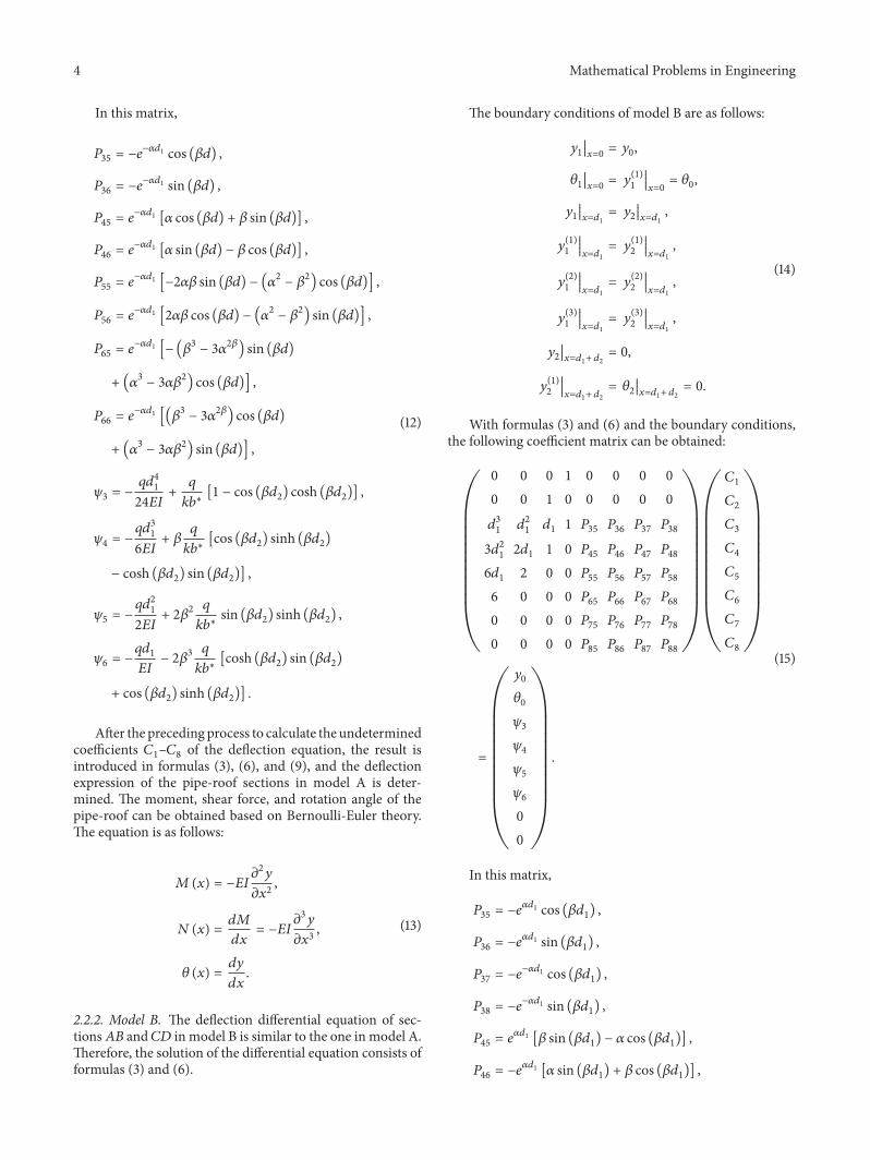
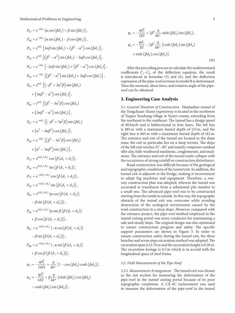
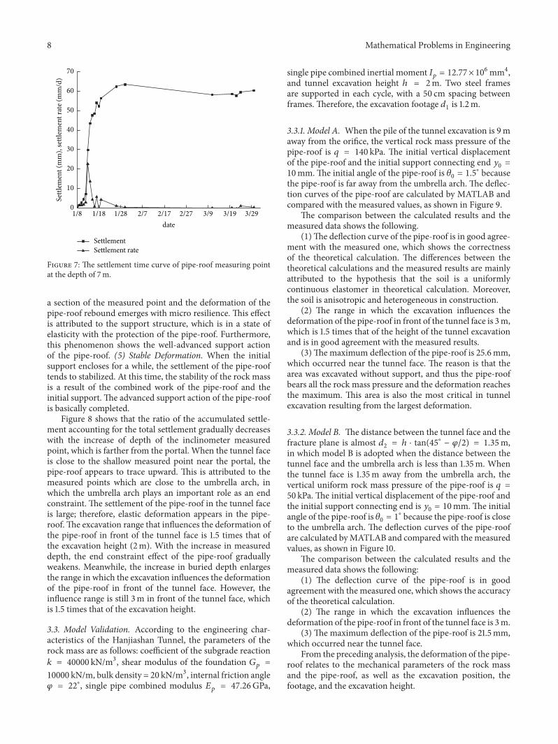
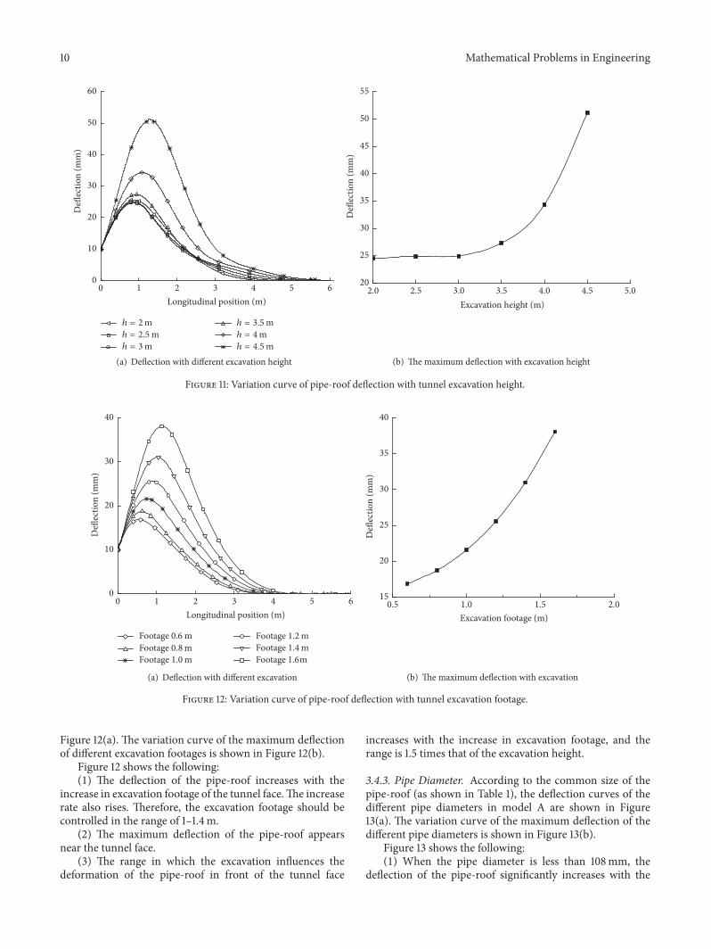