analysis of fracture on turbo expander blade tip to ... · compressor blade of high speed turbo...
TRANSCRIPT
August 2017, Volume 4, Issue 08 JETIR (ISSN-2349-5162)
JETIR1708027 Journal of Emerging Technologies and Innovative Research (JETIR) www.jetir.org 130
Analysis of Fracture on Turbo Expander Blade Tip to determine the Effect of Stress Intensity
Factor by using Finite Element Method
Aditya Shukla1, Dr. Vandana Somkuwar2 1(M.Tech Scholar Advanced Production Systems, NITTTR. Bhopal, India)
2(Head of Department, Mechanical Engineering, NITTTR. Bhopal, India)
Abstract— This paper outlines the study of
Stress and Modal behaviour of cracked
compressor blade of high speed turbo
machine. The compressor operates close to
their failure stress due to high rotational
speed of Turbo expander. Crack present in
rotating part enhances the failure effect. The
presence of crack can decrease the life;
hence it becomes very necessary to study the
fracture behaviour of the turbo expander
parts. Creo modelling software is used to
model the compressor and fracture analysis
is performed in static structural module of
ANSYS. The analysis and conclusion
presented by the author will help the
engineering society of the world to analysis,
design and fabricate turbo machinery for
better reliability and efficiency.
Key words: Turbo Expander, Fracture
Analysis, Stress intensity factor.
A detailed survey about the history of
turboexpander and its development has been
presented by Collins and Cannaday [2] and
Sixsmith [3]. Lord Rayleigh was the first to
use the concept of using a turbine in
refrigeration process in 1988. He explained
the critical functionalities of a cryogenic
expansion device, i.e. low temperature
generation instead of getting mechanical
work done. Followed by this suggestion, a
number of patents were published on
cryogenic expansion turbine. In the year
1939, a Russian scientist Peter Kapitza
demonstrated that a low pressure (4-5 bar)
liquefier using an expansion turbine would
outperform a high pressure liquefier using a
reciprocating expander. Besides having
thermodynamic superiority, the low-pressure
plant would be less expensive [4]. During
the World War II, standardized turbines
were needed. Hydraulic machine concept
was applied. Impeller parameters like
specific speed (ns) and flow coefficient (φ)
etc. became the criteria for selection of
turbines. The centrifugal inflow geometry
thus became the usual configuration for
small and medium sized cryogenic turbines
[5].
August 2017, Volume 4, Issue 08 JETIR (ISSN-2349-5162)
JETIR1708027 Journal of Emerging Technologies and Innovative Research (JETIR) www.jetir.org 131
During the period of 1960s and 70s, demand
of helium increased. Hence, the demand for
energy efficient liquefiers and refrigerators
based on turbines increased. The volumetric
flow rate in case of helium turbines is low
due to low fluid temperature and large
pressure ratio. World’s first viable turbine-
based helium liquefier was built by BOC for
the Rutherford Laboratory in Oxford. By the
end 1950s, England based company “Lucas
company” had developed a large number of
gas lubricated inward flow turbines for PDC
(Petrocarbon Development Corporation) [6].
By the 1980s, the design of turboexpanders
with gas bearings as its support became
almost popular in Europe and USA. They
built two models of small turbines, one for
helium liquefiers and another for small air
separation units. Naka Fusion Research
Centre affiliated to the Japan Atomic Energy
Institute [7] modelled a very large size He
turbo-expander. Ino et al. [8] developed a
He turbo-expander for a 70 MW
superconducting generator. The work of
Kapitza, paved the way for the Russian
Turbine industries to use both oil and gas
bearings to support turbo-expander. This has
continued through the 90s [9]. Small
turboexpanders for microcryogenic systems
have also been developed by the
Mikrokryogenmash company in Russia [4].
The development in the field like the micro
turbines and application of bearings of a
turboexpander are among various modern
developments. A tiny version of the of the
turbine for cryo-cooler was built by
Sixsmith[10] in collaboration with Goddard
Space Flight Centre of NASA.
Generally various types of turbo machines
are used for various types of application.
Depending on size they can be categorized
as small, medium and large turbo machines.
Various works has been done by Linde AG
of Germany, Creare Inc. [10] USA.
Generally shaft, expansion turbine and brake
compressor are taken for analysis of stress
and deformation, as the whole assembly is
kept in housing, there is a probability that
due to high speed rotation of the
Turboexpander, the various elements of it
may grow radially decreasing the clearance
between the housing and turbo expander.
This may cause catastrophic damage to the
housing and the turbo expander and also to
the bearings. There are sharp edges present
in shaft; brake compressor, turbine wheel,
and those are major areas of stress
concentration. As turboexpanders are very
delicate and costly, it is imperative to
analyze each and every part carefully before
putting it into application. Rotor is the
August 2017, Volume 4, Issue 08 JETIR (ISSN-2349-5162)
JETIR1708027 Journal of Emerging Technologies and Innovative Research (JETIR) www.jetir.org 132
rotating part of machine. Various types of
rotor are turbine rotor, electric rotor,
helicopter rotor, turboexpander etc. Above
all high speed rotation is required in case of
Turboexpander for cooling purpose.
Turboexpander is also known as expansion
turbine. It is having rotor, turbine and
compressor. The fluid/gas expands through
the turbine where it releases its energy to the
turbine as rotational energy, this energy is
used at the other end to compress another
fluid/gas. The expansion is isentropic
process i.e. entropy remains constant
throughout the process i.e. the change in
entropy is zero. Refrigeration industries
generally use turboexpander in their various
processes as the extraction of the gases like
ethane and NGLs (Natural Gas Liquids).
The gas at very high pressure enters into the
turbine through various piping, into the
plenum of the housing and after that into the
nozzle. The gas exit from nozzle at very
high speed and strikes the impeller radially.
The high speed gas gives torque to the rotor.
Generally converging-diverging nozzle is
used where the pressure of the gas decreases
and velocity of the gas increases at the exit.
In this nozzle the pressure energy is
transformed into the kinetic energy. The
energy always remains conserved according
to the first law of thermodynamics. As
pressure energy converts into the kinetic
energy the temperature of the gas decreases.
Torque is generated by the force transmitted
from high speed streams that strike against
the blade. The alignment between the nozzle
and the blades are made in such a way that
the effect due to sudden changes in flow
direction and loss of energy can be avoided.
The turbine wheel that is used in
Turboexpander is of radial or mixed flow
type. The radial or mixed flow turbines are
those where the flow enters the wheel
radially and exists axially. While larger units
are generally shrouded, smaller wheels are
open, the turbine housing acting as the
shroud. When the high speed flow of gas
strikes the blade of the turbine, it loses its
velocity and the energy of the fluid
decreases after the strike. The energy which
is lost is transmitted to the turbine wheel i.e.
work is extracted as the gas expands in
turbine. This work extracted can be used to
compress some other gas at another end or
generate electricity etc. Due to the loss of
energy the gas at exit is having very low
temperature below -1400C or less. These
gases can be used in cryogenic applications
like liquefaction of gases. That’s why
cryogenic industries use high speed
turboexpander for their applications.
August 2017, Volume 4, Issue 08 JETIR (ISSN-2349-5162)
JETIR1708027 Journal of Emerging Technologies and Innovative Research (JETIR) www.jetir.org 133
II. FRACTURE ANALYSIS
Fracture analysis deals with the computation
of fracture parameters. Fracture analysis
assumes the presence of a crack in the
structure. Fracture analysis is typically
carried out either using the energy criterion
or the stress-intensity-factor criterion. When
the energy criterion is used, the energy
required for a unit extension of the crack
(the energy-release rate) characterizes the
fracture toughness. When the stress-
intensity-factor criterion is used, the critical
value of the amplitude of the stress and
deformation fields characterizes the fracture
toughness.
There are three modes of Fractures studied
during fracture analysis as shown in Fig 2.
Mode I – Opening or tensile mode
Mode II – Shearing or sliding mode
Mode III – Tearing or out-of-plane mode
III. FRACTURE ANALYSIS OF
COMPRESSOR
Stress and deflection analysis have been
carried out by using ANSYS fem solver.
1) First of all the model i.e the compressor
blade and compressor are modelled using
Creo software. The model is then saved in
*.iges/*.igs format (iges stands for initial
graphics exchange specification, which is a
neutral data format file that helps in digital
exchange of data among various CAD
software).
2) This model is then imported to ANSYS.
3) Meshing of the solid model is generated
by using the meshing function of the
ANSYS finite element solver package.
4) Then various boundary conditions are
applied to the model and solved for stress
and deflection.
5) Crack is generated for studying the
fracture behaviour of the compressor.
6) Modal analysis and Fracture analysis is
studied for the model with and without
crack.
A. Boundary condition
The compressor is applied to the fixed
support at the hub to restrict its motion along
any axis.
1) Load
Centrifugal force is applied along Y-
axis (Clockwise) to the rotor.
Earth gravity is applied about Y-axis
in negative direction.
August 2017, Volume 4, Issue 08 JETIR (ISSN-2349-5162)
JETIR1708027 Journal of Emerging Technologies and Innovative Research (JETIR) www.jetir.org 134
2) Analysis and Results
Element type -3D solid element
(Tetrahedron mesh)
Number of element- 5057
Number of nodes- 2497
3) Material used – Aluminium Alloy
Density: 2700 kg/m3
Young's Modulus: 68.3 GPa
Poisson,s ratio : 0.33
4) Loading
Centrifugal load is applied to the
compressor along Y-axis (Clockwise)
having angular velocity ω = 14660 rad/s.
Earth gravity is applied about Y-axis, g =
- 9806.6 mm/s2.
B. Nomenclature
Ω - Angular velocity (rad/s)
ρ - Density of the material (kg/m3)
G - Acceleration due to gravity
(m/s2)
E - Young`s modulus (GPa)
M - Mass of the rotor (kg)
ν - Poison’s ratio (dimensionless)
N - Revolution per minute (rpm)
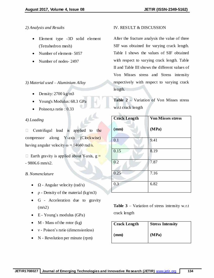
IV. RESULT & DISCUSSION
After the fracture analysis the value of three
SIF was obtained for varying crack length.
Table I shows the values of SIF obtained
with respect to varying crack length. Table
II and Table III shows the different values of
Von Misses stress and Stress intensity
respectively with respect to varying crack
length.
Table 2 – Variation of Von Misses stress
w.r.t crack length
Crack Length
(mm)
Von Misses stress
(MPa)
0.1 9.41
0.15 8.19
0.2 7.87
0.25 7.16
0.3 6.82
Table 3 – Variation of stress intensity w.r.t
crack length
Crack Length
(mm)
Stress Intensity
(MPa)
August 2017, Volume 4, Issue 08 JETIR (ISSN-2349-5162)
JETIR1708027 Journal of Emerging Technologies and Innovative Research (JETIR) www.jetir.org 135
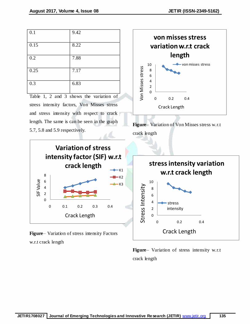
0.1 9.42
0.15 8.22
0.2 7.88
0.25 7.17
0.3 6.83
Table 1, 2 and 3 shows the variation of
stress intensity factors, Von Misses stress
and stress intensity with respect to crack
length. The same is can be seen in the graph
5.7, 5.8 and 5.9 respectively.
Figure– Variation of stress intensity Factors
w.r.t crack length
Figure– Variation of Von Misses stress w.r.t
crack length
Figure– Variation of stress intensity w.r.t
crack length
0
2
4
6
8
0 0.1 0.2 0.3 0.4
SIF
Valu
e
Crack Length
Variation of stress intensity factor (SIF) w.r.t
crack lengthK1
K2
K3
0
2
4
6
8
10
0 0.2 0.4Von
Mis
ses
stre
ss
Crack Length
von misses stress variation w.r.t crack
lengthvon misses stress
0
2
4
6
8
10
0 0.2 0.4Stre
ss In
ten
sity
Crack Length
stress intensity variation w.r.t crack length
stress intensity
August 2017, Volume 4, Issue 08 JETIR (ISSN-2349-5162)
JETIR1708027 Journal of Emerging Technologies and Innovative Research (JETIR) www.jetir.org 136
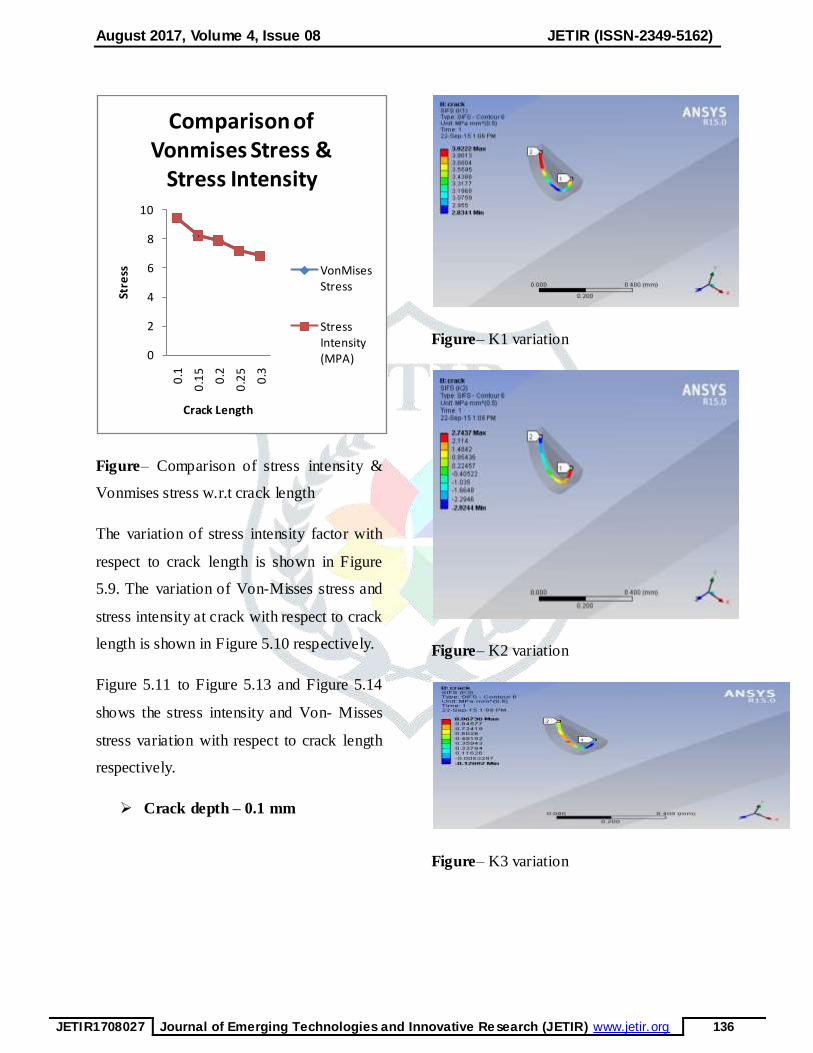
Figure– Comparison of stress intensity &
Vonmises stress w.r.t crack length
The variation of stress intensity factor with
respect to crack length is shown in Figure
5.9. The variation of Von-Misses stress and
stress intensity at crack with respect to crack
length is shown in Figure 5.10 respectively.
Figure 5.11 to Figure 5.13 and Figure 5.14
shows the stress intensity and Von- Misses
stress variation with respect to crack length
respectively.
Crack depth – 0.1 mm
Figure– K1 variation
Figure– K2 variation
Figure– K3 variation
0
2
4
6
8
10
0.1
0.1
5
0.2
0.2
5
0.3
Stre
ss
Crack Length
Comparison of Vonmises Stress &
Stress Intensity
VonMises Stress
Stress Intensity (MPA)
August 2017, Volume 4, Issue 08 JETIR (ISSN-2349-5162)
JETIR1708027 Journal of Emerging Technologies and Innovative Research (JETIR) www.jetir.org 137
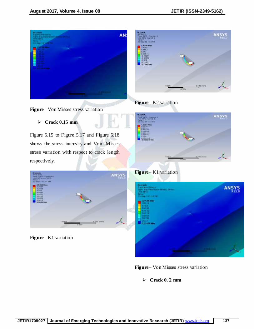
Figure– Von Misses stress variation
Crack 0.15 mm
Figure 5.15 to Figure 5.17 and Figure 5.18
shows the stress intensity and Von- Misses
stress variation with respect to crack length
respectively.
Figure– K1 variation
Figure– K2 variation
Figure– K1 variation
Figure– Von Misses stress variation
Crack 0. 2 mm
August 2017, Volume 4, Issue 08 JETIR (ISSN-2349-5162)
JETIR1708027 Journal of Emerging Technologies and Innovative Research (JETIR) www.jetir.org 138
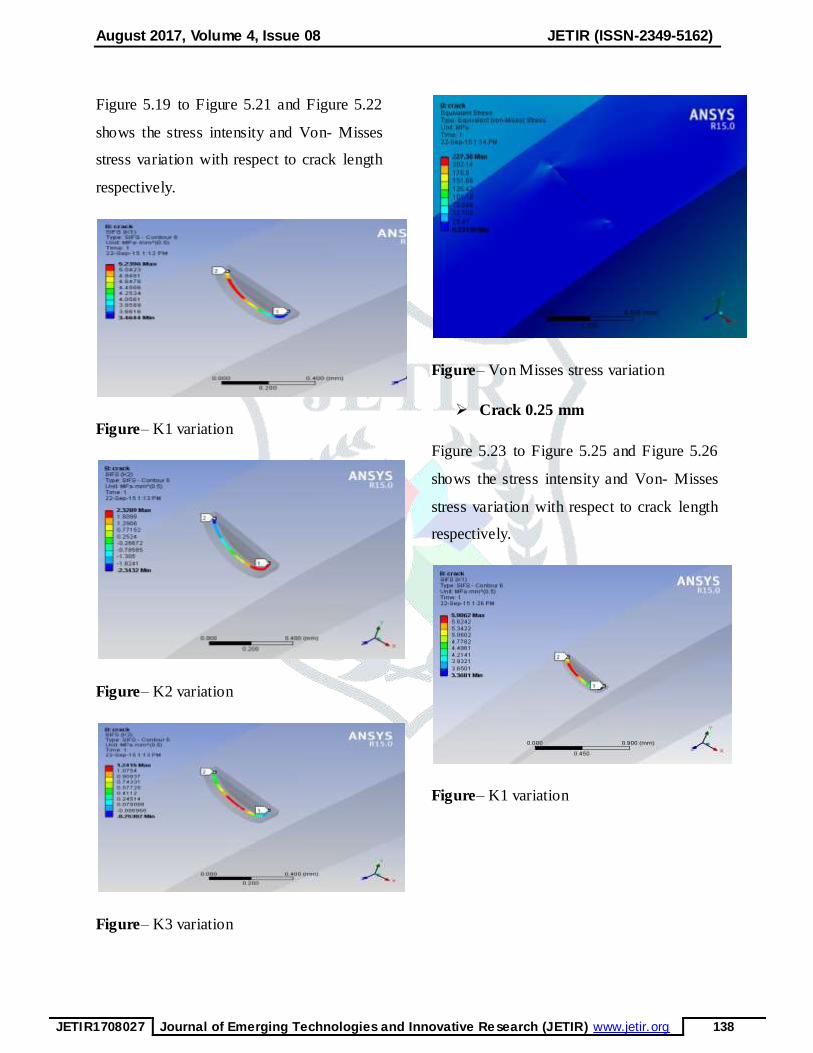
Figure 5.19 to Figure 5.21 and Figure 5.22
shows the stress intensity and Von- Misses
stress variation with respect to crack length
respectively.
Figure– K1 variation
Figure– K2 variation
Figure– K3 variation
Figure– Von Misses stress variation
Crack 0.25 mm
Figure 5.23 to Figure 5.25 and Figure 5.26
shows the stress intensity and Von- Misses
stress variation with respect to crack length
respectively.
Figure– K1 variation
August 2017, Volume 4, Issue 08 JETIR (ISSN-2349-5162)
JETIR1708027 Journal of Emerging Technologies and Innovative Research (JETIR) www.jetir.org 139
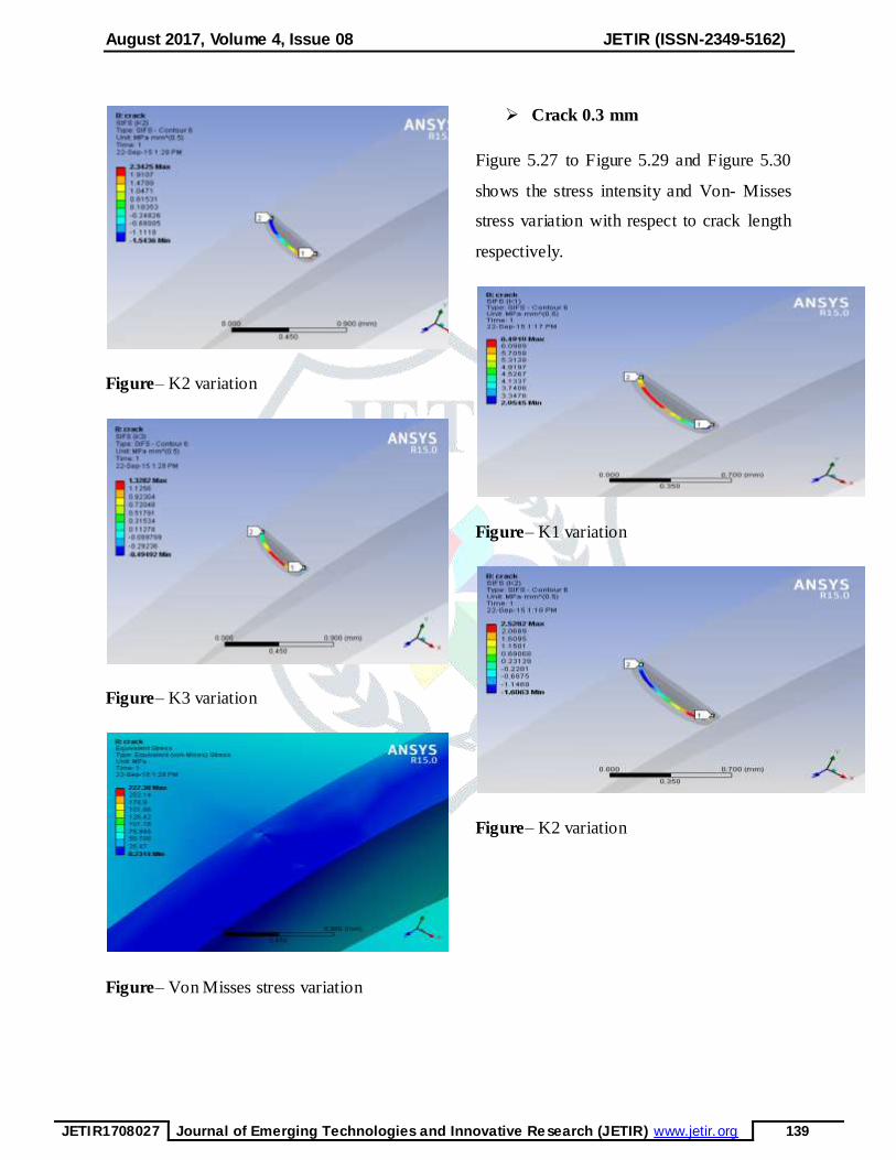
Figure– K2 variation
Figure– K3 variation
Figure– Von Misses stress variation
Crack 0.3 mm
Figure 5.27 to Figure 5.29 and Figure 5.30
shows the stress intensity and Von- Misses
stress variation with respect to crack length
respectively.
Figure– K1 variation
Figure– K2 variation
August 2017, Volume 4, Issue 08 JETIR (ISSN-2349-5162)
JETIR1708027 Journal of Emerging Technologies and Innovative Research (JETIR) www.jetir.org 140
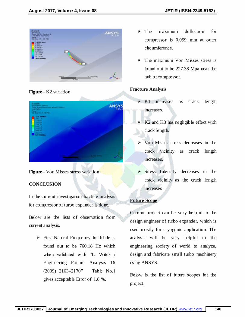
Figure– K2 variation
Figure– Von Misses stress variation
CONCLUSION
In the current investigation fracture analysis
for compressor of turbo expander is done.
Below are the lists of observation from
current analysis.
First Natural Frequency for blade is
found out to be 760.18 Hz which
when validated with “L. Witek /
Engineering Failure Analysis 16
(2009) 2163–2170” Table No.1
gives acceptable Error of 1.8 %.
The maximum deflection for
compressor is 0.059 mm at outer
circumference.
The maximum Von Misses stress is
found out to be 227.38 Mpa near the
hub of compressor.
Fracture Analysis
K1 increases as crack length
increases.
K2 and K3 has negligible effect with
crack length.
Von Misses stress decreases in the
crack vicinity as crack length
increases.
Stress Intensity decreases in the
crack vicinity as the crack length
increases
Future Scope
Current project can be very helpful to the
design engineer of turbo expander, which is
used mostly for cryogenic application. The
analysis will be very helpful to the
engineering society of world to analyze,
design and fabricate small turbo machinery
using ANSYS.
Below is the list of future scopes for the
project:

August 2017, Volume 4, Issue 08 JETIR (ISSN-2349-5162)
JETIR1708027 Journal of Emerging Technologies and Innovative Research (JETIR) www.jetir.org 141
1. All components of turbo expander
namely rotor, compressor and
expansion turbine can be combined
together and a detail analysis can be
done to study the critical areas using
ANSYS.
2. An analytical analysis of high speed
rotor, compressor and expansion
turbine using Finite Element Method
can be done and compared with the
result obtained from the ANSYS
software.
3. Bearings for such high speed turbo
machines are critical parts, so
analysis of bearings are needed to
complete design of turbo machines.
REFERENCES
[1] Ghosh P., Analytical and
Experimental Studies on Cryogenic
Turboexpander, Ph. D. dissertation,
IIT Kharagpur (2002).
[2] Goel S.K, Theoretical and
Experimental Investigation of a Shaft
Disc System with a Crack, B.Tech.
dissertation, NIT Rourkela(2008).
[3] Y. D. Kim And C. W. Lee , Journal
Of Sound And Vibration. Finite
Element Analysis Of Rotor Bearing
Systems Using A Modal
Transformation Matrix (1986).
[4] D Martande, S. G. Kolgiri, Nitin S
Motgi, IJAIEM (Volume 2, Issue 7,
July 2013)Stress Analysis for Rotor
Shaft of Electric Motor.
[5] T. R. Chandrupatla, A.D
Belegundu, Finite Elements in
Engineering, New Delhi, PHI private
Limited, (2008)
[6] Collins, S.C. and Cannaday, R.L.
Expansion Machines for Low
Temperature Processes Oxford
University Press (1958)
[7] Sixsmith, H. Miniature cryogenic
expansion turbines - a review Adv
Cryo Eng (1984) 29 511-523
[8] Reuter K. and Keenan B. A.
Cryogenic turboexpanders with
magnetic bearings
AICHESymposium Series, Cryogenic
Processes and Machinery.
[9] Creare Inc, USA www.creare.com
[10] Kun, L .C. and Sentz, R. N.
High efficiency expansion turbines
in air separation and liquefaction
plants International Conference on
Production and Purification of Coal
August 2017, Volume 4, Issue 08 JETIR (ISSN-2349-5162)
JETIR1708027 Journal of Emerging Technologies and Innovative Research (JETIR) www.jetir.org 142
Gas & Separation of Air, Beijing,
China (1985) 1 – 21
[11] Kapitza, P. J. Phys. Ac. Sci.
USSR.1, No.7, p29 (1939)
[12] Dixon, S. L. Fluid
Mechanics and Thermodynamics of
Turbomachinery (3rd ed) Pergamon
Press (1978)
[13] Kato T, Miyake, A. Kawno,
K. Hamada,K., Hiyama, T.,
Iwamoto, S., Ebisu, H., Tsuli,
H.,Saji, N., Kaneko, Y., Asakura,
H., Kuboto, M., Nagai, S. Design
and test of wet type Turboexpander
with an alternator as Adv Cryo engg
(1994)
[14] Ino, N., Machida, A., and
Ttsugawa, K., Development of high
expansion ratio He turboexpander
Adv Cryo Eng (1992) 37B 835-844
[15] Polishchuk, E. L.,
Shanklankin V. I. and Lyapin V. I.
Self-contained microcryogenic
system with a turboexpander
Khimicheskoe I Neftyanoe
Mashinostroenie (Trans: Chemical &
Petroleum Engg) (1991) V 27 (3/4)
P217.
[16] Sixsmith, H., Valenjuela, J.
and Swift, W. L. Small Brayton
cryocoolers Adv Cryo Eng (1988)
[17] Land, M. L. Expansion
turbines and engines for low
temperature processes Adv CryoEng
(1957)
[18] Beasley, S. A. and Halford,
P. Development of a High Purity
Nitrogen Plant using Expansion
Turbine with Gas Bearing Adv Cryo
Eng (1965).
[19] Jadeja, H. T., Mitter, A.
and Chakrabarty, H. D.
Turboexpander application for
cryoprocessing of nitrogen and related gases
Proceedings of INCONCRYO85 Indian
Cryogenic Council Tata McGraw (1985).
[20] Witek, Lucjan.
"Experimental crack propagation and
failure analysis of the first stage
compressor blade subjected to
vibration." Engineering failure
analysis 16.7 (2009): 2163-2170.
[21] Poursaeidi, Esmaeil, and
Hosein Bakhtiari. "Fatigue crack

August 2017, Volume 4, Issue 08 JETIR (ISSN-2349-5162)
JETIR1708027 Journal of Emerging Technologies and Innovative Research (JETIR) www.jetir.org 143
growth simulation in a first stage of
compressor blade." Engineering
Failure Analysis 45 (2014): 314-325.
[22] Witek, Lucjan. "Simulation
of crack growth in the compressor
blade subjected to resonant vibration
using hybrid method." Engineering
Failure Analysis 49 (2015): 57-66.
[23]