analysis of dynamic pressure puild-up in twin-tube … · in twin-tube vehicle shock ......
TRANSCRIPT

© Z
F S
ach
s A
G
Analysis of Dynamic Pressure Puild-up
in Twin-tube Vehicle Shock Absorbers
with Respect to Vehicle Acoustics
Vehicle Dynamics Expo 2008
Dr.-Ing. Alexander Kruse ZF Sachs AG

DTT-6 / A. Kruse 2 © Z
F S
ach
s A
G
Overview
� Damping principle
� Description of processes in shock absorber valves
� Vibration analysis of shock absorber hydraulics
� Optimization of the dynamic vibration behavior
� Summary

DTT-6 / A. Kruse 3 © Z
F S
ach
s A
G
Damping principle of a twin-tube shock absorber
upper working chamber
lower working chamber
compensating chamber

DTT-6 / A. Kruse 4 © Z
F S
ach
s A
G
Damper Measuring at the Test Rig
F/v diagram F/s diagram Force, displacement, piston rod acceleration
diagram
Frequency spectrum ofpiston rod acceleration
Force
Piston rod acceleration
Displacement
Sound pressure
Servohydraulic Test RigData acquisition and analyse

DTT-6 / A. Kruse 5 © Z
F S
ach
s A
G
Comparison of F/v diagrams of shock absorber statically “– „dynamically“
Rebound
Compression
Excitation 2 Hz, 41mm, 0.5m/s Excitation 25 Hz, 3,3mm, 0.5m/s
Shock absorber velocity

DTT-6 / A. Kruse 6 © Z
F S
ach
s A
G
Shock absorber displacementDamping forcePiston rod acceleration
Damper Measuring at the Test Rig
Excitation 0.5m/s (2 Hz, 41mm) Excitation 0.5m/s (25 Hz, 3,3mm)
Highly dynamic excitation brings significant differences to the described "quasi-static" behavior of the shock absorber

DTT-6 / A. Kruse 7 © Z
F S
ach
s A
G
Load cell
Test arrangement on rig
1
Shock absorber
Acceleration sensor
Test rig frame
Sensors
Test rig actuator
2
4
5
6
3

DTT-6 / A. Kruse 8 © Z
F S
ach
s A
G
“Quasi-static" behavior of the shock absorber
Time, s
Comp Reb
BRV
p_lower p_upper
D_F
PR_aD_W
D_WBCV
Measuring signals at excitation of 2 Hz and velocity of 1,0 m/s
D_W - shock absorber displacement
D_F - damping force
PR_a - piston rod acceleration
p_upper - oil pressure in upper working chamber
p_lower - oil pressure in lower workingchamber
p_ausgl - oil pressure in compensatingchamber
BRV - lift of base replenishing valve
BCV - lift of base compression valve
The processes occurring in the shock absorber correspond to classic concepts. Piston and base valves open at the defined shock absorber design speed (0.2 – 0.3 m/s).

DTT-6 / A. Kruse 9 © Z
F S
ach
s A
G
Measuring of damper characteristics
Time [s]
0.006 0.008 0.01 0.012 0.014 0.016 0.018 0.02 0.022 0.024 0.026
0.006 0.00
8
0.01 0.012 0.014 0.01
6
0.018 0.02 0.022 0.024 0.026Time [s]
D_W
D_W
BCV
p_upper
p_lower
D_F
PR_a
0 1 2 3
Drop D_W - shock absorber displacement
D_F - damping force
PR_a - piston rod acceleration,
p_upper - oil pressure in upper working chamber
p_lower - oil pressure in lower working chamber
p_ausgl - oil pressure in compensating chamber
BRV - lift of base replenishing valve
BCV - lift of base compression valve
With high-frequency excitation, both working chambers are under far greater hydraulic pressure at the reversal point than with slow excitation. The maximum damping force is reached shortly after the start of the compression stage.
high-frequency excitation of 25 Hz and a shock absorber velocity of 1,0 m/s

DTT-6 / A. Kruse 10 © Z
F S
ach
s A
G
Valve opening phases
BCV
BCV
KDV
KDV
BRV
BRV
KZV
KZV
0 180 360
Excita
tion
fre
qu
en
cy
BDV
BDV
KDV
KDV
BRV
BRV
KZV
KZV
0 180 360
BDV
BDV
KDV
KDV
BRV
BRV
KZV
KZV
0 180 360
BDV
BDV
KDV
KDV
BRV
BRV
KZV
KZ
BCV
BCV
PCV
PCV
BRV
BRV
PRV
PRV
Phase φ°0 180 360
2 Hz
25 Hz
High-frequency excitation causes a length reduction of the opening time in thecase of check valves (delay on opening and premature closing) and extension of the opening time (delay on closing and premature opening) of the main valves
Excitation
frequency, Hz
Ratio
p upper chamber/p lower chamber
Phase φ at maximum
damping force
φ= 0° φ= 180° Compressi
on
Rebound
2 1.5 1.0 90° 270°
25 8 3 20° 290°
These phase shift cause problems in harmonic pressure and force build-up
"quasi-static" and highly dynamic shock absorber excitation
DTT-6 / A. Kruse 11 © Z
F S
ach
s A
G
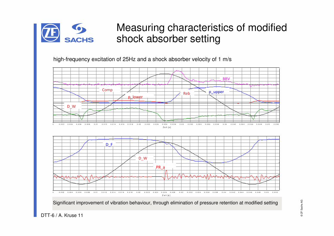
Measuring characteristics of modified shock absorber setting
high-frequency excitation of 25Hz and a shock absorber velocity of 1 m/s
Significant improvement of vibration behaviour, through elimination of pressure retention at modified setting
0 0 .0 0 2 0 . 0 0 4 0 .0 0 6 0 .0 0 8 0 . 0 1 0 .0 1 2 0 . 0 1 4 0 .0 1 6 0 .0 1 8 0 . 0 2 0 .0 2 2 0 . 0 2 4 0 .0 2 6 0 .0 2 8 0 .0 3 0 .0 3 2 0 . 0 3 4 0 .0 3 6 0 .0 3 8 0 .0 4 0 .0 4 2 0 . 0 4 4 0 .0 4 6 0 .0 4 8 0 .0 5 0 .0 5 2
Z e i t [s ]
- 3 5 0 0
- 3 0 0 0
- 2 5 0 0
- 2 0 0 0
- 1 5 0 0
- 1 0 0 0
- 5 0 0
0
5 0 0
1 0 0 0
0 0 .0 0 2 0 .0 0 4 0 .0 0 6 0 . 0 0 8 0 . 0 1 0 .0 1 2 0 .0 1 4 0 . 0 1 6 0 . 0 1 8 0 . 0 2 0 .0 2 2 0 .0 2 4 0 . 0 2 6 0 .0 2 8 0 .0 3 0 .0 3 2 0 . 0 3 4 0 . 0 3 6 0 .0 3 8 0 . 0 4 0 .0 4 2 0 . 0 4 4 0 .0 4 6 0 .0 4 8 0 .0 5 0 .0 5 2
Z e it [ s ]
CompReb
BRV
p_lower
p_upper
D_F
PR_a
D_W
D_W

DTT-6 / A. Kruse 12 © Z
F S
ach
s A
G
Summary
� Analysis of the dynamic vibration processes going on in the working chambers showed that the damping force irregularities and noise occur at the start of valve opening
� Improvement of dynamic pressure build-up through valve optimization brought distinct noise reduction
� With knowledge of the valve operating characteristics in conjunction with the internal pressure characteristics, effective optimization strategies can be pursued

DTT-6 / A. Kruse 13 © Z
F S
ach
s A
G
Thank you very much for your attention!