analysis of direct sensor-to-embedded systems...
TRANSCRIPT

International Journal of Intelligent Mechatronics and Robotics, 2(1), 41-56, January-March 2012 41
Copyright © 2012, IGI Global. Copying or distributing in print or electronic forms without written permission of IGI Global is prohibited.
Keywords: Accuracy,ComplexProgrammableLogicDevice(CPLD),FieldProgrammableGateArray(FPGA),Micro-Controller,Precision,Sensors
INTRODUCTION
Traditionally, analog sensors are interfaced to embedded systems via a combination of signal conditioning electronics and an analog-to-digital converter (ADC). Typically, some, or all, of the signal conditioning electronics is integrated in the sensor circuit and the ADC is typically integrated in the embedded control-ler. Figure 1 illustrates a typical distribution of
components between the “sensor” circuit and the “system” circuit.
During the last decade, there’s been a trend towards interfacing sensors directly to micro-controllers, without the use of ADCs (Cox, 1997; Merritt, 1999; Custodio et al., 2001; Jordana et al., 2003; Reverter et al., 2005; Lepowski, 2004; Reverter & Pallàs-Areny, 2006). The major advantage is that this re-duces the overall cost of the acquisition system. The main idea is to transfer the analog signal variation caused by the sensor, into a quasi digital signal that can be measured by one of
Analysis of Direct Sensor-to-Embedded Systems Interfacing:
A Comparison of Targets’ PerformanceLarsE.Bengtsson,UniversityofGothenburg,Sweden
ABSTRACTThispaperisconcernedwiththedirectinterfacingofresistivesensorstodifferentembeddedtargets.Theauthorusestheideaof“directsensor-to-microcontroller”techniquewhereanalogsensorsareinterfaceddirectlytoinherentlydigitalcontrollersandwecomparetheperformanceofthistechniquewhenappliedtoatypicalmicrocontroller(PIC18),aCPLDandanFPGA.Experimentalresultsshowthat5Vsystems,likethePIC18controller,haveanadvantageover3.3Vsystemsintermsofbetterprecisionperformance,whiletheCPLDoutperformsboththemicrocontrollerandtheFPGAintermsofaccuracy.Theaccuracydependsmainlyontheoutputimpedanceofthesystem’sI/Oportsandtheprecisiondependsmainlyontriggerlevelnoise.ThePIC18controlleralsohasthebestperformanceintermsoflinearityandsensitivity.Alotofworkshavebeenpublishedconcerningdirectinterfacingtomicrocontrollers,butlittleattentionhasbeenpaidtoalternativetargetslikeCPLDandFPGA.ThisworkwillbenchmarkthesedifferentkindsoftargetsandprovethatthedirectinterfacingtechniquecanalsobeappliedtoCPLDsandFPGAs.
DOI: 10.4018/ijimr.2012010103

42 International Journal of Intelligent Mechatronics and Robotics, 2(1), 41-56, January-March 2012
Copyright © 2012, IGI Global. Copying or distributing in print or electronic forms without written permission of IGI Global is prohibited.
the controller’s embedded timers. A variation in an analog voltage is transferred into an ana-log variation in either frequency, time duration or duty cycle (“quasi digital”) as illustrated in Figure 2 (Reverter & Pallàs-Areny, 2005; Vio-rel, 2006).
Quasi digital signals are easily measured by any embedded system with a standard timer; measuring analog variations in time is easier (and more cost efficient) than measuring variations in an analog voltage. Also, perfor-
mance parameters like dynamic range and noise immunity, typically improve when you measure a variation in time instead of a variation in analog voltage (Pallàs-Areny & Webster, 2001).
Exactly how this direct sensor interfacing is implemented depends on the sensor, whether it is resistive, capacitive or part of a Wheatstone bridge or not. We treat only resistive sensors (not being part of a bridge circuit) here. This includes, for example, common RTDs (Resis-tive Thermal Devices) like the Pt-1000 sensor.
Figure1.Traditionaldataacquisitionsystem
Figure2.Analogsignalsaretransferredintoquasidigitalsignals
Figure3.Directinterfacingofresistivesensor

International Journal of Intelligent Mechatronics and Robotics, 2(1), 41-56, January-March 2012 43
Copyright © 2012, IGI Global. Copying or distributing in print or electronic forms without written permission of IGI Global is prohibited.
Figure 3 illustrates the basic idea of how a resistive sensor is interfaced directly to a controller.
During the first stage, I/O pin 2 is config-ured as output and set high while I/O pin 1 is configured as input (high impedance). I/O pin 2 will charge the capacitor to VOH (I/O pin output high level). During the second stage, the pins are reconfigured; pin 2 becomes high impedance and pin 1 is configured as an output pin and set low. Hence the capacitor will dis-charge through the sensing element’s resistance RS. The discharging continues until the voltage on pin 2 reaches the threshold level for input logic low (VIL). Figure 4 shows the charge/discharge timing diagram on I/O pin 2.
An internal timer measures the discharging time TS in Figure 4, resulting in an integer NS which is proportional to TS. This number is proportional to the resistance of the sensing element (Merritt, 1999):
R kNS S= (1)
where the constant k depends on the trigger level threshold of the embedded timer, the capacitor C and also on the controller’s speed and timer setup parameters (clock rate, pre-scale).
In this work we will compare the perfor-mance of three different kinds of embedded targets when they are used in direct (resistive)
sensor-to-controller applications. The first target is an 8-bit PIC18F458 microcontroller from Microchip (Microchip, 2003). The second one is a CPLD (Complex Programmable Logic Device) EMP3064A from Altera (2006) and the third target is an FPGA (Field Programmable Gate Array) EP2C20, also from Altera (2008).
Any embedded target used for direct sensor-to-controller purposes, must have the following properties:
• Bidirectional I/O pins and the ability to change the direction of the I/O pins in software.
• I/O-pins must have tri-state capability; a high impedance (high-Z) state must be available for I/O-pins (in order to prevent current sinking during some stages of the charge/discharging process).
• A timer must exist (with at least 16 bits resolution)
• Preferably it needs some serial interface (RS-232 or USB) in order to transmit data to a host PC.
For conventional microcontrollers like the PIC18 family, this is not a problem since all I/O pins’ data direction is easily changed by manipulating the controller’s TRIS registers (Microchip, 2003). The CPLD and the FPGA circuits are programmed in VHDL and I/O pins
Figure4.Charging/DischargingatI/O-pin2

44 International Journal of Intelligent Mechatronics and Robotics, 2(1), 41-56, January-March 2012
Copyright © 2012, IGI Global. Copying or distributing in print or electronic forms without written permission of IGI Global is prohibited.
are made bidirectional by defining them as “inout” ports in the entity and they can be set to a high-Z state if they are declared as std_logic types. An std_logic type signal in VHDL has no less than eleven logic states (0, 1 and nine more) (Hamblen et al., 2008; Pedroni, 2004). Typically most of these nine extra states are not synthesizable in most targets, but one of them, the “high output impedance” state (‘Z’) is, which makes CPLDs/FPGAs potential targets for direct sensor-to-controller applications.
RELATED WORK
Cox (1997) was one of the first to suggest how to interface resistive sensors directly to microcontrollers, without the use of interme-diate ADCs. He proposed an extra calibration resistor RC and a “protection” resistor RP, as illustrated in Figure 5.
By timing the discharging of C both via the sensor RS and via the calibration resistor RC, the unknown sensor resistance RS can be esti-mated as a quotient (Cox, 1997):
R̂T
TR
N
NRS
S
CC
S
CC= = (2)
where NS and NC are the integer numbers produced by the controller’s timer during the discharging through RS and RC, respectively.
Compared to Eq. (1), the expression is now independent of the capacitor C (Still, the overallperformance is not independent of C) (Jordana et al., 2003; Reverter & Pallàs-Areny, 2006). The measurement time is of course increased, but the introduction of a calibration cycle removes/reduces all first order errors in offset, gain and temperature (Cox, 1997). Cox (1997) also suggested a protection resistor RP, in order to protect the sinking I/O pin from ESD (Electro-Static Discharge) related breakdowns.
When it comes to selecting component values, Cox (1997) suggested that you should pick an RC value that is one half of the maximum expected RS, RP should be a “small” resistor (100-200 ohms) and the charging capacitor should be
CT
RVVST
R
=−
⋅ −
ln 1
(3)
where T is the charging time necessary to get the desired resolution and VR and VT are the start and stop levels of the charging process, re-spectively. Reverter, Gasulla, and Pallàs-Areny (2005), would later show that the RP resistor is also necessary in order to reduce power supply interferences.
Figure5.Theone-pointcalibrationtechnique

International Journal of Intelligent Mechatronics and Robotics, 2(1), 41-56, January-March 2012 45
Copyright © 2012, IGI Global. Copying or distributing in print or electronic forms without written permission of IGI Global is prohibited.
Previous to Cox (1997), Bierl (1996) had suggested a two-point calibration technique, with one extra calibration resistor as in Figure 6.
In this case, the sensor’s resistance is es-timated from
R̂N N
N NR R RS
S C
C CC C C=
−−
⋅ −( )+1
2 12 1 1
(4)
Reverter, Jordana, Gasulla, and Pallàs-Areny (2005) would later analyze both the one- and two-point calibration technique and conclude that the accuracy of the RS measure-ments in both cases depends on the I/O-ports’ internal resistances Ri. However, in the one-point calibration case, the error is of the order of Ri, while in the two-point calibration case, the error is of the order of ΔRij, i.e., the difference in internal resistance of the I/O-pins. Hence, from an accuracy point of view, the two-point calibration method is preferred (but the mea-surement time increases and hence the system bandwidth is reduced). As far as precision (uncertainty) is concerned, Reverter, Jordana, Gasulla, and Pallàs-Areny (2005) concluded that the one- and two-point calibration techniques yield similar results. The same work also sug-gested a “three-signal” calibration technique, which basically has the same performance as
the two-point calibration technique but has better cost-performance ratio, since only one calibration resistor is required.
In 2001, Custodio et al. (2001) published a work that analyzed the importance of select-ing the right calibration resistor in more detail. They analyzed in detail the influence of the microcontroller’s internal parameters on the uncertainty of the discharging time measure-ment. The parameters included not only the current leakage of the I/O pins, but also the influence of non-ideal input/output resistances. Their model of the microcontroller’s I/O pins showed that there are accuracy errors propor-tional to the I/O pin’s output resistance. They also suggested gain errors if the two I/O pins’ output parameters were not identical, and also quantified the non-linearity errors. One conclu-sion was that all these errors only existed when RC ≠ RS and suggested that RC is chosen as close to the midrange value of RS as possible (which agrees with Cox’s (1997) suggestion, even if Cox’s motivation was less detailed). The selec-tion of C, suggested by Custodio et al. (2001), is that if you want an n-bit resolution representing the maximum and minimum values of RS, then
C
f RV VV V
n
SOH OL
OH IH
>
⋅−−
2
∆ ln
(5)
Figure6.Thetwo-pointcalibrationtechnique

46 International Journal of Intelligent Mechatronics and Robotics, 2(1), 41-56, January-March 2012
Copyright © 2012, IGI Global. Copying or distributing in print or electronic forms without written permission of IGI Global is prohibited.
where f= timer’s counting rate, ΔRS = RS,max – RS,min, VOH is the output voltage of an output pin set high, VOL is the output voltage of an output pin set low and VIH, is the high level threshold of an input pin.
Reverter et al. (2003a) reported that the program code influences the power consump-tion of the microcontroller. Certain code instruc-tions (jump and call) cause spike interferences in the power supply. Since the I/O pins’ input trigger levels depend on the power supply, the trigger levels are code dependent. Results showed that jump/call instructions executed regularly in loops with a period of τ, could cause a quantization error of ±τ (compared to the timer’s inherent ±1 uncertainty). This was only observed in slow slewing signals and some solutions were suggested; the use of an external Schmitt-trigger (ST) and the necessity of a decoupling capacitor for the power sup-ply voltage. Later, Reverter and Pallàs-Areny (2004) and Reverter and Pallàs-Areny (2006) would suggest that the microcontroller should be put into low-power mode during the time measurement in order to reduce the firmware induced uncertainties.
The need for decoupling capacitors in direct sensor-to-microcontroller circuits was further investigated by Jordana et al. (2003). They concluded that a decoupling capacitor was necessary in order to reduce the trigger uncertainties caused by power supply fluctua-tions. The size of the decoupling capacitor was not critical; increasing the decoupling capacitor above 100 nF did not significantly improve their results. Jordana et al. (2003) also investigated the influence of the charging/discharging capaci-tor. While a large capacitor is attractive since it increases the charging time and therefore reduces the relative influence of the inherent quantization error of the timer, a small capacitor has the benefit of increasing the signal’s slew rate and therefore reduces the uncertainties caused by internal trigger level noise. They tried to find a reasonable compromise between the error-uncertainty-time parameters influenced by the choice of C. They found that the standard
deviation of the measured resistance increased with C but they found no distinct relationship between the relative error and C. They sug-gested C = 1.5 μF as a reasonable compromise between error-uncertainty-time considerations in the case of a Pt-1000 RTD.
Reverter et al. (2003b) reported in 2003 the benefits of timing the discharging of the capacitor rather than the charging. The reason is that experimental results showed that the trigger level noise was smaller for the I/O-pin’s lower threshold level (used at discharging) than for the higher threshold level (used at charg-ing). This work also showed that the trigger level was more susceptible to signal noise than power supply noise. These results were later confirmed by Reverter et al. (2004), where also the time measurement’s dependence on the noise frequency was studied. The trigger uncertainty was reported to increase when sinusoidal noise was added to either the input signal or the power supply and was particularly severe when the noise frequency was close to that of the measured signal. Temperature varia-tions and time drifts were reported not to affect the measurement.
The effective number of bits (ENOB) of the time-to-digital conversion involved in the discharging time measurement was thoroughly analyzed by Reverter and Pallás-Areny (2004) and they found that the ENOB depends on the RC time constant only up to some particular time. For small RC values, the quantization uncertainties dominate and the ENOB improves with increasing RC values. However, the conse-quence of increasing RC is that the signal slew rate decreases at the trigger point and hence trigger level noise uncertainties increase. At some point, trigger level noise will dominate over quantization noise and from that point, increasing RC does not improve ENOB. Hence, there is an optimal measurement speed-ENOB combination for each sensor interface. In the reported experiment, this optimal combination was observed at RC ≈ 2-3 ms.
In Reverter, Jordana, Gasulla, and Pallàs-Areny (2005) the influence of power supply interferences on the discharging time measure-

International Journal of Intelligent Mechatronics and Robotics, 2(1), 41-56, January-March 2012 47
Copyright © 2012, IGI Global. Copying or distributing in print or electronic forms without written permission of IGI Global is prohibited.
ment was investigated. It was shown that power supply interferences did not influence the ac-curacy as much as the resolution and that these interferences are most severe at low frequencies. It was recommended that the analog and digital power supplies be separated.
AIM OF THIS WORK
The aim of any measurement is to produce an estimate x̂ of some unknown quantityx0 . The deviation of x̂ from the true value x0 is the accuracy (or error) of the estimate:
Accuracy = −x̂ x0 (6)
The statistical spread of a number of esti-mators, x̂i , is the uncertainty or precision of the estimator and we will use the standard deviation s x̂( ) to quantify the estimator’s precision:
Precision = ( )s x̂ (7)
The aim of this work is to find out what the best approach is to direct sensor-to-embedded system in terms of what kind of embedded target to use. We will compare accuracy and precision of a typical 8-bit microcontroller, a CPLD and an FPGA.
Accuracy Analysis
According to Custodio et al. (2001), the main contribution to the estimator’s accuracy in direct sensor-to-controller applications is the I/O-pins’ output resistance (since it add directly to the sensor’s resistance during discharging). The output resistance of a typical I/O pin on our three targets was measured as described by Reverter, Jordana, Gasulla, and Pallàs-Areny, (2005) and is summarized in Table 1.
ROH and ROL is the output resistance of an I/O pin when set “high” and “low”, respec-tively. Since we measure the discharging time, it is ROL that is our main concern here and that
will determine the accuracy. From Table 1 it is clear that in terms of accuracy, we expect the CPLD to outperform both the PIC controller and the FPGA.
Precision Analysis
Quantization and trigger level noise have been reported to be the main uncertainty sources (Jordana et al., 2003; Reverter et al., 2004a; Reverter, Jordana, Gasulla, & Pallàs-Areny, 2005) and for slow slewing signals, as in direct sensor-to-controller applications, the trigger noise dominates (Jordana et al., 2003). Ac-cording to Bouwens (1984) the trigger noise of digital counters is inversely dependent on the signal slew rate:
u kSRtrigg =1 (8)
The signal slew rate is the gradient at the VIL level in the discharging stage in Figure 4. Assuming VOL = 0 (Sedra & Smith, 1991), the voltage across the capacitor during discharg-ing is
V t VC OHt RC( ) = ⋅ −e (9)
and the time to reach the VIL level is
t RCV
VILIL
OH
= − ⋅ ln (10)
The signal slew rate affecting the trigger noise is the discharging signal’s gradient at the VIL level, i.e., at time tIL:
dV
dt RCV SR tCOH
t RC= − ⋅ = ( )−1e
(11)
dV
dt RCV
V
V RCV SR tC
t tOH
IL
OHIL IL
IL=
= − ⋅ ⋅ = − ⋅ = ( )1 1
(12)

48 International Journal of Intelligent Mechatronics and Robotics, 2(1), 41-56, January-March 2012
Copyright © 2012, IGI Global. Copying or distributing in print or electronic forms without written permission of IGI Global is prohibited.
From Eq. (12) we can see that the slew rate depends directly on VIL. This parameter was measured for each one of our three targets and the results are illustrated in Table 2. (Notice that the CPLD and FPGA are both 3.3 V systems.)
It is obvious from Table 2 that the use of +5 V supply voltage in the PIC controller sys-tem seems to be favorable when it comes to precision performance since this will result in a higher slew rate at the threshold level. As far as precision is concerned we expect the PIC controller to offer the best performance while we don’t expect to see any major difference between the other targets.
METHODS AND EQUIPMENT
Hardware
Since the purpose of this work only was to establish the best type of target to use in direct sensor-to-embedded controller applications, either the one-point (Figure 5) or the two-point (Figure 6) calibration technique could be used. Since the one-point calibration technique is less complex and hence easier to implement, the one-point calibration technique was implemented in all three targets. In order to simulate a Pt-1000
RTD sensor, fixed resistors were used, ranging from 817.41 Ω to 2193.95 Ω. For a Pt-1000 RTD, these resistor values correspond to a temperature range of approximately −47 °C to +310 °C. For all targets, the register contents of the embedded timer measuring the discharging time were transferred to a LabVIEW program on a PC computer via an RS-232 interface (COM-port). This requires a level converter circuit (TTL-to-RS232), a MAX232 (Maxim, 2011), and in accordance to recommendations by Reverter et al. (2003b), the MAX232 cir-cuit and the embedded controller were always supplied from separate sources. Both supply voltages were decoupled with a 1 μF capacitor which agrees with recommendations by Jordana et al. (2003).
The RP resistor was 150 Ω (Reverter, Ga-sulla, & Pallàs-Areny, 2005) and the calibration resistor RC was 1495.03 Ω, which is close to the midrange value of RS (Cox, 1997; Custodio et al., 2001).
For all targets a 16-bit timer, updated at a rate of 1 MHz, was invoked to measure the dis-charging time. The exact value of the charging/discharging capacitor was chosen after careful considerations. Using Eq. (3), suggested by Cox (1997), we get C ≈ 10 μF. Aiming for a resolution of at least 10 bits, Eq. (5) (Custodio
Table1.Outputresistanceofourembeddedtargets
Table2.VoltagelevelsoftypicalI/Opins

International Journal of Intelligent Mechatronics and Robotics, 2(1), 41-56, January-March 2012 49
Copyright © 2012, IGI Global. Copying or distributing in print or electronic forms without written permission of IGI Global is prohibited.
et al., 2001) results in a capacitor value of at least 3 μF. Reverter and Pallàs-Areny (2004) found in a similar setup, that an RC constant of 2-3 ms should be appropriate, indicating a C value of at least 2 μF (however they used a timer clock rate of 4 MHz).
Taking all these previously reported sug-gestions into account, a C value of 4.7 μF was finally used.
The PIC18F458 controller came in a 40-pin DIP package (Dual In Package), the CPLD was a 44-pin PLCC package (Plastic Leaded Chip Carrier) and the FPGA was a 484-pin Fine Line BGA package (Ball Grid Array). The FPGA used in this work was the one that comes on the Altera’s DE1 Development and Education board (Altera, 2011) and the components in Figure 5 were connected to the FPGA’s I/O-pins via an available I/O-expansion connector. For the PIC18 and the CPLD, PCBs (printed circuit boards) were designed at an in-house workshop.
Software
The software is uncomplicated and can be implemented in a number of different ways. Referring to Figure 5, the flowchart diagram in Figure 7 illustrates the software.
Both the CPLD and the FPGA were pro-grammed in VHDL and in these cases the flowchart in Figure 7 was transferred into a simple state machine since this would minimize the VHDL code size (which is particularly important in the CPLD case since it only con-tains 64 macro cells) (Altera, 2006). The state machine is illustrated in Figure 8.
In the CPLD case this state machine oc-cupied 38 macro cells of the 64 macro cells available in the EMP3064A. (In order to make it fit into the CPLD, the compiler needs to be configured to “optimize for area”.) In all cases, some standard software was added for the purpose of transferring the discharging times to the LabVIEW program on the host PC via the RS-232 interface.
DISCUSSION OF RESULTS
Figure 9 shows a typical charging/discharging diagram in the PIC18 case, when RS = 2193.95 ohms. The “long” discharging times correspond to the RS resistor and the “short” discharging times correspond to the RC resistor (1495.03 ohms). Compare this diagram with Table 2. The corresponding diagrams for the FPGA and the CPLD looked very similar and agreed very well to the numbers in Table 2.
For all targets, the discharging time was measured approximately 500 times and the mean and standard deviation were calculated and the mean was transferred to resistance us-ing equation (2). Tables 3, 4 and 5 show the results.
From these tables, all our predictions are verified; the PIC18 microcontroller has the smallest standard deviation in all measurements, i.e., the overall best precision. This confirms that the PIC18’s higher slow rate at the VIL level is indeed favorable since it reduces the noise effects on the trigger level. This is also illustrated in Figures 10 and 11, where we compare the histograms of the PIC18 and the CPLD when RS = 1502.12 ohms. The nar-rower histogram of the PIC18’s data was veri-fied in all measurements.
From tables 3 through 5 we can also see that our prediction about the accuracy perfor-mance is also indeed verified; in terms of ac-curacy, the CPLD outperforms both the PIC18 and the FPGA.
The results are summarized in Figure 12. However, poor precision performance due to random noise is only a matter of averaging enough samples. Figure 12 shows the results for 500 samples in each case. The CPLD can achieve the same precision as the PIC18 controller, but it would take twice as many samples (1.98) and hence the system’s overall bandwidth would be reduced by a factor of two. Hence, choosing between a PIC18 controller and a CPLD is only an accuracy-precision-bandwidth tradeoff.
It should be noted that Reverter and Pallàs-Arreny (2006) have suggested further methods in order to reduce the uncertainty when using

50 International Journal of Intelligent Mechatronics and Robotics, 2(1), 41-56, January-March 2012
Copyright © 2012, IGI Global. Copying or distributing in print or electronic forms without written permission of IGI Global is prohibited.
microcontrollers; the use of a low-power mode that doesn’t stop the embedded timer and that can be recovered by external interrupts. The PIC controller used here has indeed that option; Timer1 can run during sleep mode and it can also be revitalized by an interrupt generated by
the capture module (Microchip, 2003). Hence, the width of the PIC18’s distribution diagram in Figure 12 could probably be reduced even more. This suggests that it would take even more samples in the CPLD case to reach the precision of the PIC18.
Figure7.Softwareflowchart
Figure8.Directsensor-to-embeddedsystemstatemachine

International Journal of Intelligent Mechatronics and Robotics, 2(1), 41-56, January-March 2012 51
Copyright © 2012, IGI Global. Copying or distributing in print or electronic forms without written permission of IGI Global is prohibited.
Figure9.Asnapshotofthecharging/dischargingprocess
Table3.PIC18F458performancedata
Table4.CPLDEMP3064Aperformancedata

52 International Journal of Intelligent Mechatronics and Robotics, 2(1), 41-56, January-March 2012
Copyright © 2012, IGI Global. Copying or distributing in print or electronic forms without written permission of IGI Global is prohibited.
Table5.CycloneIIEP2C20performancedata
Figure10.TypicalhistogramofPIC18data
Figure11.TypicalhistogramofCPLDdata

International Journal of Intelligent Mechatronics and Robotics, 2(1), 41-56, January-March 2012 53
Copyright © 2012, IGI Global. Copying or distributing in print or electronic forms without written permission of IGI Global is prohibited.
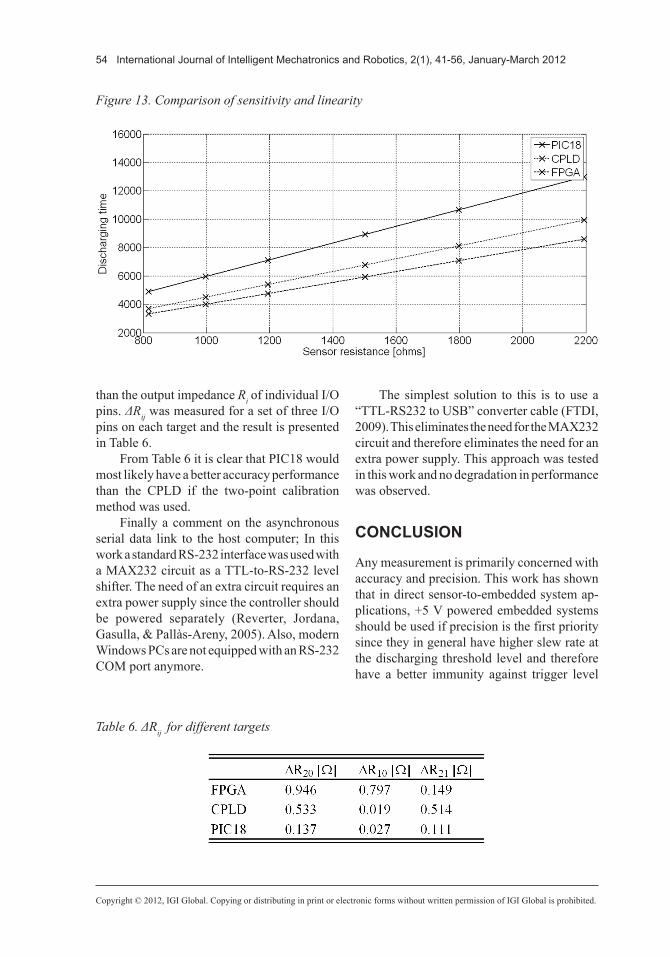
So far we have only considered accuracy and precision. Other parameters of interest in this kind of measurements are sensitivity and linearity. In Figure 13 we have plotted the dis-charging times produced by each system as a function of the sensor’s resistance.
From this diagram it is obvious that the +5 V powered microcontroller has yet another advantage over the other targets; it has better sensitivity; 5.88 counts/ohm compared to 4.52 and 3.83 counts/ohm for the CPLD and the FPGA respectively. Hence the PIC18 will be able to detect smaller changes in the sensor’s output. By fitting each set of data to a straight line, the linearity of each sensor was also mea-sured and the linearity of the PIC18 data was a factor of 10 better than the CPLD/FPGA data (0.01% and 0.10% respectively).
The reason for the differences in, for ex-ample accuracy performance, lies of course in the manufacturing technology and manufactur-ers aren’t very detailed about this in their data sheets (Microchip, 2003; Altera, 2006, 2008). In general though, even if microcontrollers, CPLDs and FPGAs have very different archi-tectures (Brown & Rose, 2000), the digital I/O pins are almost always designed as the output of a flip-flop. However, they can be imple-mented in a number of different technologies
(NMOS, CMOS, TTL, etc.) (Sedra & Smith, 1991) and the manufacturing process itself may differ; the production of a semiconductor is a multi-step process including crystal growth, wafer manufacturing, photolithography, silicon oxidizing, oxide deposition, etching, diffusion, ion implantation etc. (Quirk & Serda, 2001). Hence, even if all targets have flip-flop outputs, there are plenty of reasons why the performance and parameters of the final semiconductor would differ, and the actual parameters need to be examined for each unique situation. The results obtained in this work are not claimed to be general, but will serve as a guideline when selecting embedded targets for direct sensor-to-embedded system applications.
It appears that the PIC18 system (or similar +5 V powered microcontrollers) is the best choice of embedded target for direct sensor-to-embedded system implementations. In this work it was only outperformed by the CPLD in accuracy. In any other respect, it showed the overall best performance. When it comes to accuracy, the two-point calibration method (Reverter, Jordana, Gasulla, & Pallàs-Areny, 2005) should be considered if the loss of bandwidth is acceptable. The accuracy will then be proportional to the differenceΔRij in output impedance between two I/O pins rather
Figure12.Performancesummaryofourthreetargets
54 International Journal of Intelligent Mechatronics and Robotics, 2(1), 41-56, January-March 2012
Copyright © 2012, IGI Global. Copying or distributing in print or electronic forms without written permission of IGI Global is prohibited.
than the output impedance Ri of individual I/O pins. ΔRij was measured for a set of three I/O pins on each target and the result is presented in Table 6.
From Table 6 it is clear that PIC18 would most likely have a better accuracy performance than the CPLD if the two-point calibration method was used.
Finally a comment on the asynchronous serial data link to the host computer; In this work a standard RS-232 interface was used with a MAX232 circuit as a TTL-to-RS-232 level shifter. The need of an extra circuit requires an extra power supply since the controller should be powered separately (Reverter, Jordana, Gasulla, & Pallàs-Areny, 2005). Also, modern Windows PCs are not equipped with an RS-232 COM port anymore.
The simplest solution to this is to use a “TTL-RS232 to USB” converter cable (FTDI, 2009). This eliminates the need for the MAX232 circuit and therefore eliminates the need for an extra power supply. This approach was tested in this work and no degradation in performance was observed.
CONCLUSION
Any measurement is primarily concerned with accuracy and precision. This work has shown that in direct sensor-to-embedded system ap-plications, +5 V powered embedded systems should be used if precision is the first priority since they in general have higher slew rate at the discharging threshold level and therefore have a better immunity against trigger level
Figure13.Comparisonofsensitivityandlinearity
Table6.ΔRijfordifferenttargets

International Journal of Intelligent Mechatronics and Robotics, 2(1), 41-56, January-March 2012 55
Copyright © 2012, IGI Global. Copying or distributing in print or electronic forms without written permission of IGI Global is prohibited.
noise compared to +3.3 V powered systems like CPLDs/FPGAs.
However, the accuracy in direct sensor-to-embedded systems applications are mostly depending on the output impedance of the embedded system’s I/O-pins, and this work has shown that CPLDs exist that outperform a typical microcontroller in this respect.
REFERENCES
Altera. (2006). MAX3000A programmable logicdevicefamily. Retrieved May 18, 2011, from http://www.altera.com/literature/ds/m3000a.pdf
Altera. (2008). Cyclone II device handbook. Re-trieved May 31, 2011, from http://www.altera.com/literature/hb/cyc2/ cyc2_cii5v1.pdf
Altera. (2011). DE1 development and educationboard. Retrieved June 24, 2011, from http://www.altera.com/education/univ/ materials/boards/de1/unv-de1-board.html
Bierl, L. (1996). Precise measurements with theMSP430. Waltham, MA: Texas Instruments.
Bouwens, A. J. (1984). Digitalinstrumentation. New York, NY: McGraw-Hill.
Brown, S., & Rose, J. (2011). ArchitectureofCPLDsandFPGAs:Atutorial. Retrieved August 14, 2011, from http://www.eecg. toronto.edu/~jayar/pubs/brown/survey.pdf
Cox, D. (1997). Implementingohmmeter/temperaturesensor(ApplicationNoteNo.AN512). Chandler, AZ: Microchip Technology.
Custodio, A., Pallàs-Arreny, R., & Bragós, R. (2001). Error analysis and reduction for a simple sensor-microcontroller interface. IEEE Transac-tionsonInstrumentationandMeasurement, 50(6). doi:10.1109/19.982960
FTDI. (2009). TTLtoUSBserialconvertergenericcabledatasheet. Retrieved August 15, 2011, from http://www.ftdichip.com/ Support/Documents/DataSheets/Cables/DS_TTL-232RG_CABLES.pdf
Hamblen, J. O., Hall, T. S., & Furman, M. D. (2008). Rapidprototypingofdigitalsystems. New York, NY: Springer. doi:10.1007/978-0-387-72671-7
Jordana, J., Reverter, F., & Pallàs-Areny, R. (2003, May 20-22). Uncertainty in resistance measurements based on microcontrollers with embedded time counters. In ProceedingsoftheInstrumentationandMeasurementTechnologyConference, Vail, CO.
Lepkowski, J. (2004). Temperature measurementcircuitsforembeddedapplications(ApplicationNoteNo.AN929). Chandler, AZ: Microchip Technology.
Maxim. (2010). +5V-Powered,MultichannelRS-232Drivers/Receivers, 19-4323, Rev 16. Sunnyvale, CA: Maxim Integrated Products. Retrieved June 11, 2011, from http://datasheets. maxim-ic.com/en/ds/MAX220-MAX249.pdf
Merritt, B. (1999). MPS430baseddigitalthermom-eter (Application Report No. SLAA038). Waltham, MA: Texas Instruments.
Microchip. (2003). PIC18FXX8 Data Sheet (Re-port No. DS41159C). Chandler, AZ: Microchip Technology.
Pallás-Areny, R., & Webster, J. G. (2001). Sensorsandsignalconditioning (2nd ed.). New York, NY: John Wiley & Sons.
Pedroni, V. A. (2004). CircuitDesignwithVHDL. Cambridge, MA: MIT Press.
Quirk, M., & Serda, J. (2001). Semiconductormanufacturing technology. Upper Saddle River, NJ: Prentice Hall.
Reverter, F., Casas, O., Jordana, J., & Pallás-Areny, R. (2004). Trigger uncertainty in period-to-code converters based on counters embedded in micro-controllers. SensorsandActuators.A,Physical, 110, 439–446. doi:10.1016/j.sna.2003.09.003
Reverter, F., Gasulla, M., & Pallàs-Areny, R. (2005, May 17-19). Analysis of power supply interference effects on direct sensor-to-microcontroller interfaces. In ProceedingsoftheInstrumentationandMeasure-mentTechnologyConference, Ottawa, ON, Canada.
Reverter, F., Jordana, J., Gasulla, M., & Pallàs-Areny, R. (2005). Accuracy and resolution of direct resis-tive sensor-to-microcontroller interfaces. Elsevier:SensorsandActuatorsA, 121, 78–87. doi:10.1016/j.sna.2005.01.010
Reverter, F., Jordana, J., & Pallàs-Areny, R. (2003a, May 20-22). Program-dependent uncertainty in period-to-code converters based on counters em-bedded in microcontrollers. In ProceedingsoftheInstrumentation and Measurement TechnologyConference, Vail, CO.

56 International Journal of Intelligent Mechatronics and Robotics, 2(1), 41-56, January-March 2012
Copyright © 2012, IGI Global. Copying or distributing in print or electronic forms without written permission of IGI Global is prohibited.
Reverter, F., Jordana, J., & Pallàs-Areny, R. (2003b, June 22-27). Internal trigger errors in microcontroller-based measurement. In Proceedings of the 17thIMEKOWorldCongress, Dubrovnik, Croatia.
Reverter, F., & Pallàs-Areny, R. (2004). Effective number of resolution bits in direct sensor-to-microcontroller interfaces. Measurement Science&Technology, 15, 2157–2162. doi:10.1088/0957-0233/15/10/028
Reverter, F., & Pallàs-Areny, R. (2005). Directsensor-to-microcontroller interface circuits. Barcelona, Spain: Maracombo.
Reverter, F., & Pallàs-Areny, R. (2006). Uncertainty reduction techniques in microcontroller-based time measurements. Elsevier:SensorsandActuatorsA, 127, 74–79. doi:10.1016/j.sna.2005.11.015
Sedra, A. S., & Smith, K. C. (1991). Microelectroniccircuits (3rd ed.). Orlando, FL: Saunders College.
Viorel, C. P. (2006, October 16-17). Microcontroller based measurements: how to take out the best we can of them. In Proceedingsofthe8thWSEASInter-nationalConferenceonMathematicalMethodsandComputationalTechniquesinElectricalEngineering, Bucharest, Hungary.
LarsE.Bengtsson,born1963,receivedhisMScDegreeinPhysicsin1987andaresearchdegreeinPhysicsin1991(PhL,LicentiateofPhilosophyinPhysics)attheUniversityofGothenburg.LBwasanass.prof.atChalmersUniversityofTechnologyinSwedenfrom1997to2007andtransferredtoGothenburgUniversityin2007.Hismajorteaching/researchareasareembeddedsystemsandelectricalmeasurementsystems.