analysis of characteristic heat pipe as an...
TRANSCRIPT

ANALYSIS OF CHARACTERISTIC HEAT PIPE AS AN EFFICIENT COOLING HEAT TRANSFER DEVICE
NORMAN HAFIZI BIN ALFAN
A thesis is submitted in Fulfilment of the requirement for the award of the
Degree of Master of Mechanical Engineering
Faculty of Mechanical and Manufacturing Engineering Universiti Tun Hussein Onn Malaysia
JUNE 2013

v
ABSTRACT
A heat pipe is a simple heat transfer device that can transport large
quantities of heat with a very small difference in temperature between the hot
ends to the other end. In this case study, the concept of the condensation process
of heat pipe is applied in order to perform dehumidification process to remove
extra moisture inside the air. The objective of this study is to compare the
efficiency between the primary heat pipe in evacuated condition and the
secondary heat pipe with water as the working fluid in order to perform the
dehumidification process. The heat pipe device had been divided into 2 samples
of specimens. First specimen of heat pipe using air whiles the other one used
water as the working fluid. These two pipes were made without the wick but
dealing with inclination of angle to see the performance of the heat pipe. These
two heat pipes were built without the wick but dealing with inclination of angle to
see the performance of the heat pipe. Both pipes were built by the total length of
400mm length and 8mm diameter using copper as the pipe material. Gravity
pumping was used with the inclination angle to pump back the working fluid back
to the evaporator section. The heat pipe was positioned at different angles of 0°,
30°, 60° and 90° with the horizontal. To achieve the objective of this study, both
pipes were studied experimental and simulation to find the most efficiency
between the primary heat pipe and the secondary heat pipe. The important
parameter involves in the case study are the Merit Number, M and Heat Transfer
Coefficient. After performing the experiments and simulation, the objective of
this case study is achieved, which showed the secondary heat pipe is more
efficient as a cooling heat transfer device.

vi
ABSTRAK
Paip haba adalah alat ringkas pemindahan haba yang digunakan untuk
memindahkan haba yang banyak dengan perbezaan kecil pada suhu di pangkal
paip dengan di hujung paip. Dalam kajian kes ini, konsep kondensasi pada paip
haba itu digunakan untuk dehumidification kandungan air di dalam udara.
Objektif kajian ini ialah untuk membandingkan kecekapan paip haba primer yang
mengandungi udara di dalamnya dengan paip haba sekunder yang mengandungi
bendalir penggerak untuk menjalankan proses dehumidification. Paip haba
tersebut dibahagikan kepada dua contoh spesimen. Spesimen pertama paip haba
menggunakan udara manakala spesimen kedua menggunakan air sebagai bendalir
penggerak. Kedua-dua paip ini dibina tanpa sumbu di dalamnya akan tetapi
menggunakan perbezaan darjah untuk melihat keberkesanan medium dalam
kedua-dua paip haba tersebut. Tarikan graviti digunakan melalui perubahan setiap
darjah dengan tujuan untuk mengepam bendalir balik ke bahagian penyejatan.
Kedua-dua paip ini diletakkan pada perbezaan darjah pada 0°, 30°, 60° dan 90°
dalam keadaan melintang. Untuk mencapai objektif kajian ini, dua paip haba ini
duji dengan melakukan eksperimentasi dan simulasi CFD untuk mencari
kecekapan antara paip haba primer dan haba paip sekunder. Parameter penting
yang berkaitan dalam kajian ini adalah seperti Merit Number, M dan juga Heat
Transfer Coefficient. Setelah melakukan eksperimental dan simulasi CFD
eksperimen berkaitan, objektif kajian ini tercapai dan hasilnya terbukti paip haba
sekunder mempunyai kecekapan yang lebih berbanding dengan paip haba primer.
vii
TABLE OF CONTENTS
TITLE i
DECLARATION ii
DEDICATION iii
ACKNOWLEDGEMENT iv
ABSTRACT v
ABSTRAK vi
CONTENTS vii
LIST OF FIGURES xii
LIST OF TABLES xv
LIST OF SYMBOL xvii
LIST OF APPENDICES xix
CHAPTER 1 INTRODUCTION 1
1.1 Introduction to Research 1
1.2 Background of the Study 2
1.3 Problem Statement 3
1.4 Objectives of the Study 3
1.5 Scopes of Study 4
1.6 Thesis Outline 4
CHAPTER 2 LITERATURE REVIEW 7
2.1 Introduction 7
2.2 Heat Pipe Analysis Characteristics 8
2.3 Description of Heat Pipe 9
2.4 The Construction of a heat pipe 10

viii
2.4.1 Heat pipe design consideration
2.4.2 Heat pipe selection
2.4.3 Working fluid
2.4.4 Material
10
13
14
16
2.5 Heat Pipe Operation 16
2.6 Heat Pipe Application in Solar Thermal Collector 18
2.6.1 Evacuated Tube Solar Collector
2.6.2 Heat pipe concept in evacuated tube
solar collector
19
22
CHAPTER 3 METHODOLOGY 23
3.1 Introduction 23
3.2 Research Design 24
3.3 Data Analysis 26
3.3.1 Merit Number, M
3.3.2 Reynolds Number, Re
3.3.3 Volume Flow Rate
3.3.4 Average Velocity
3.3.5 Heat Transfer Coefficient
26
31
31
32
32
3.4 Experimental Setup 33
3.4.1 Description
3.4.2 Heat pipe preparation
3.4.2.1 Vacuum conditions in heat pipe
3.4.2.2 Working fluid inside the heat pipe
3.4.3 Physical Characteristics
3.4.4 Specimen categories
3.4.4.1 Primary heat pipe
3.4.4.2 Secondary heat pipe
3.4.5 Experimental procedures
33
34
36
36
40
41
42
42
43
ix
3.4.5.1 Before the experiment
3.4.5.2 During the experiment
3.4.5.3 After the experiment
43
44
47
3.5 CFD Analysis 47
3.5.1 Fluid Flow in Pipes
3.5.2 Modeling Description
3.5.3 Boundary Conditions
3.5.4 Governing Equations
3.5.5 The CFD process
3.5.5.1 Pre-processing step
3.5.5.2 Solving step
3.5.5.3 Post-processing step
48
50
51
56
57
57
59
59
CHAPTER 4 RESULTS AND DISCUSSIONS 60
4.1 Introduction 60
4.2 Data Analysis of Heat Pipes 61
4.2.1 Data collections of heat pipes D2 section
at 0° angle
4.2.2 Data collections of heat pipes D3 section
at 0° angle
4.2.3 Graphical data collections of heat pipes at
0° angle
4.2.4 Data collections of heat pipes D2 section
at 30° angle
4.2.5 Data collections of heat pipes D3 section
at 30° angle
4.2.6 Graphical data collections of heat pipes at
30° angle
4.2.7 Data collections of heat pipes D2 section
61
62
63
64
65
66
67

x
at 60° angle
4.2.8 Data collections of heat pipes D3 section
at 60° angle
4.2.9 Graphical data collections of heat pipes at
60° angle
4.2.10 Data collections of heat pipes D2 section
at 90° angle
4.2.11 Data collections of heat pipes D3 section
at 90° angle
4.2.12 Graphical data collections of heat pipes at
90° angle
68
69
70
71
72
4.3 Analysis of Heat Pipes Results 73
4.3.1 Results of Merit Number, M
4.3.2 Temperature Contour of Primary Heat
Pipe
4.3.3 Temperature Contour of Secondary Heat
Pipe
74
75
79
4.4 Discussions 85
4.4.1 Heat pipes at 0° angle
4.4.2 Heat pipes at 30° angle
4.4.3 Heat pipes at 60° angle
4.4.4 Heat pipes at 90° angle
85
87
89
91
4.5 Summary of Merit Number, M 93
CHAPTER 5 CONCLUSION AND RECOMMENDATIONS 94
5.1 Introduction 94
5.2 Summary of research study in heat pipes 94
5.3 Conclusion 96
5.4 Recommendations 98

xi
REFERENCES 100
APPENDICES 102

xii
LIST OF FIGURES
FIGURE TITLE PAGE
1.1 The flow process of the case study 6
2.1 (a) Heat pipe using gravity pumping 12
2.1 (b) Heat pipe using wick pumping 12
2.2 The conventional of heat pipe diagram 13
2.3 Pressure variation along a heat pipe 17
2.4 Schematic view and the main regions the heat pipe 17
2.5 Schematic and operation of a heat pipe 18
2.6 Evacuated Solar Collector (with heat pipe technology) 19
2.7 Glass tube of evacuated tube collector 20
2.8 Heat transfer process in evacuated tube solar collector 20
2.9 Heat pipe operates in an evacuated tube solar collector 22
3.1 Flow chat of project plan 25
3.2 Copper tubes with hollow shaft without wick 34
3.3 Heat pipe the original condition (left) and after the welding
operation (right)
35
3.4 Secondary heat pipe after drilling operation at the D3 section 35
3.5 Syringes are used to vacuum and supply the water inside the
secondary pipe
36
3.6 The secondary heat pipe after vacuum condition and water
inside it
37
3.7 Primary heat pipe (above) and secondary heat pipe (below) 37
3.8 Schematic diagram of heat pipe with the apparatus used in the
experiment
38

xiii
3.9 The experimental set up of heat pipe in laboratory 38
3.10 Physical model of the heat pipe 41
3.11 A small cloth wrapped around the heat pipe clamp with the
retort stand
44
3.12 Heat pipe at the position of 0° inclination angle 45
3.13 Heat pipe at the position of 30° inclination angle 45
3.14 Heat pipe at the position of 60° inclination angle 46
3.15 Heat pipe at the position of 90° inclination angle 46
3.16 A process of an optimization design procedure 48
3.17 Schematic geometry of heat pipe design 51
3.18 Boundary conditions of heat pipe design 52
3.19 Length of the location for thermocouple sensors 55
3.20 Location of the thermocouple sensors in the experimental
study
55
3.21 Solid modeler of heat pipe 58
3.22 Mesh generator of heat pipe 58
3.23 An overview of CFD Modeling Process 59
4.1 D2 section of heat pipes at 0° angle 63
4.2 D3 section of heat pipes at 0° angle 63
4.3 D2 section of heat pipes at 30° angle 66
4.4 D3 section of heat pipes at 30° angle 66
4.5 D2 section of heat pipes at 60° angle 69
4.6 D3 section of heat pipes at 60° angle 69
4.7 D2 section of heat pipes at 90° angle 72
4.8 D3 section of heat pipes at 90° angle 72
4.9 Temperature contour of primary heat pipe adiabatic at 0° angle 75
4.10 Temperature contour of primary heat pipe without adiabatic at
0° angle
75
xiv
4.11 Temperature contour of primary heat pipe adiabatic at 30°
angle
76
4.12 Temperature contour of primary heat pipe without adiabatic at
30° angle
76
4.13 Temperature contour of primary heat pipe adiabatic at 60°
angle
77
4.14 Temperature contour of primary heat pipe without adiabatic at
60° angle
77
4.15 Temperature contour of primary heat pipe adiabatic at 90°
angle
78
4.16 Temperature contour of primary heat pipe without adiabatic at
90° angle
78
4.17 Temperature contour of secondary heat pipe adiabatic at 0°
angle
79
4.18 Temperature contour of secondary heat pipe without adiabatic
at 0° angle
79
4.19 Temperature contour of secondary heat pipe adiabatic at 30°
angle
80
4.20 Temperature contour of secondary heat pipe without adiabatic
at 30° angle
80
4.21 Temperature contour of secondary heat pipe adiabatic at 60°
angle
81
4.22 Temperature contour of secondary heat pipe without adiabatic
at 60° angle
81
4.23 Temperature contour of secondary heat pipe adiabatic at 90°
angle
82
4.24 Temperature contour of secondary heat pipe without adiabatic
at 90° angle
82
5.1 Configuration of the two-phase closed thermosyphon 99

xv
LIST OF TABLES
TABLE TITLE PAGE
2.1 Typical operating characteristics of heat pipe 15
2.2 Evacuated Tube Solar Collector Specifications 21
3.1 Density of air at different temperature 27
3.2 Density of water at different temperature 28
3.3 Dynamic viscosities of some fluids 29
3.4 Value of surface tension at different temperature 30
3.5 The reference details of the apparatus in the experimental
study
39
3.6 Experimental variables 41
3.7 The differentiation between the primary and secondary heat
pipe
43
3.8 Types of the fluid flows 49
3.9 The boundary conditions of adiabatic in heat pipe modelling 53
3.10 The boundary conditions without adiabatic in heat pipe
modelling
54
3.11 Meshing report for heat pipe modeling 58
4.1 Data collections of primary and secondary heat pipe D2
section at 0° angle
61
4.2 Data collections of primary and secondary heat pipe D3
section at 0° angle
62
4.3 Data collections of primary and secondary heat pipe D2
section at 30° angle
64

xvi
4.4 Data collections of primary and secondary heat pipe D3
section at 30° angle
65
4.5 Data collections of primary and secondary heat pipe D2
section at 60° angle
67
4.6 Data collections of primary and secondary heat pipe D3
section at 60° angle
68
4.7 Data collections of primary and secondary heat pipe D2
section at 90° angle
70
4.8 Data collections of primary and secondary heat pipe D3
section at 90° angle
71
4.9 The maximum temperature of heat pipes in every angle at D2
section
74
4.10 The maximum temperature of heat pipes in every angle at D3
section
74
4.11 The comparison data of maximum possible heat transport
between primary and secondary heat pipe at D2 section
74
4.12 The comparison data of maximum possible heat transport
between primary and secondary heat pipe for D3 section
74
4.13 Comparison of experimental and steady state temperature by
CFD analysis in primary heat pipe
83
4.14 Comparison of experimental and steady state temperature by
CFD analysis in secondary heat pipe
84
4.15 The summary of maximum possible heat transport using both
pipes at various angles for D2 and D3 sections
93
5.1 Summary of Primary Heat Pipe 96
5.2 Summary of Secondary Heat Pipe 97
xvii
LIST OF SYMBOL
FIGURE TITLE
CFD - Computational Fluid Dynamics
ACT - Advanced Cooling Technologies
NASA - National Aerospace Agency
HPHE - Heat Pipe Heat Exchanger
USB - Universal Serial Bus
atm - Atmosphere
°C - Degree Celsius
T - Temperature
t - Time
W - Watts
M - Merit Number, M
K - Kelvin ρ - Density of working fluid in liquid phase
σ - Surface tension of the working fluid µ - Dynamic viscosity of working fluid in liquid phase
L - Length of the heat pipe
Le - Length of evaporator section
La Length of adiabatic section
Lc - Length of condenser section
m - Meter
mm - Millimeter
Re - Reynolds Number
V - Velocity, Average Velocity

xviii
c - Specific heat
k - Thermal conductivity
qQ , - Rate of internal heat generation
Φ - Dissipation function due to the viscous forces
D,d - Diameter
r - Radius
h - Heat transfer coefficients
H - Heights
π - Pi (radian)
∆ - Increment
V - Volume flow rate
cA - Cross sectional area
sA - Heat transfer surface area
sT - Temperature of the surface
∞T - Temperature of the fluid sufficiently far from the surface
ml - Millilitre
l - Litre
gal - Gallons
xix
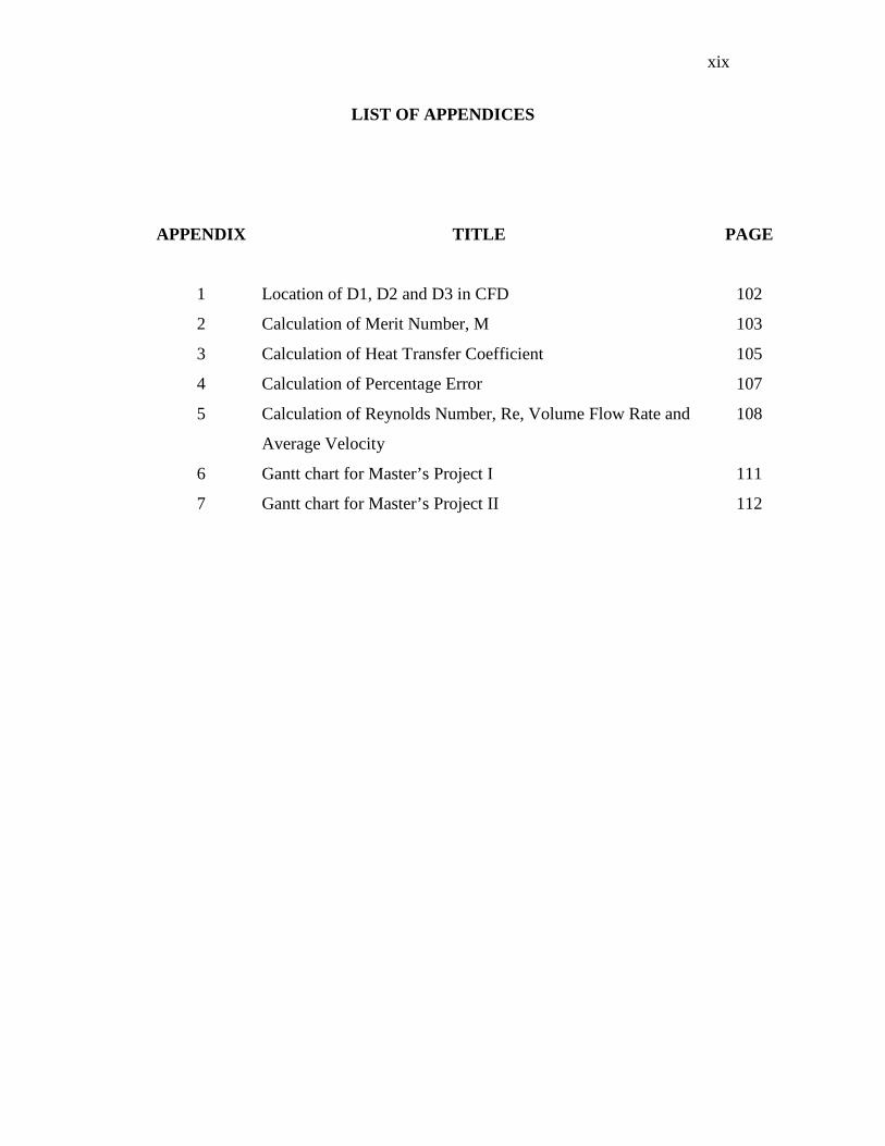
LIST OF APPENDICES
APPENDIX TITLE PAGE
1 Location of D1, D2 and D3 in CFD 102
2 Calculation of Merit Number, M 103
3 Calculation of Heat Transfer Coefficient 105
4 Calculation of Percentage Error 107
5 Calculation of Reynolds Number, Re, Volume Flow Rate and
Average Velocity
108
6 Gantt chart for Master’s Project I 111
7 Gantt chart for Master’s Project II 112

CHAPTER 1
INTRODUCTION
1.1 Introduction to Research
Heat Pipe
A heat pipe is a heat transfer mechanism that can transport large quantities of heat
with a very small difference in temperature between the hot ends to the other end. In
other words, it is a simple device that can quickly transfer heat from one point to another.
They are often referred to as the "superconductors" of heat as they possess an extra
ordinary heat transfer capacity and rate with almost no heat loss.
Basically, it consists of a sealed aluminum or copper container whose inner
surfaces have a capillary wicking material. A heat pipe is similar to a thermosyphon. It
differs from a thermosyphon by virtue of its ability to transport heat against gravity by an
evaporation-condensation cycle with the help of porous capillaries that form the wick.
The wick provides the capillary driving force to return the condensate to the evaporator.
The quality and type of wick usually determines the performance of the heat pipe, for this
is the heart of the product. Different types of wicks are used depending on the application
for which the heat pipe is being used.
1

1.2 Background of the Study
The range of its application is extremely wide and enormous. Some of the fields
in which it is extensively used nowadays are listed below:
a) Electronics:
All electronic components, from microprocessors to high end power converters
generate heat and rejection of this heat is necessary for their optimum and reliable
operation. As electronic design allows higher throughput in smaller packages, dissipating
the heat load becomes a critical design factor. Many of today’s electronic devices require
cooling beyond the capability of standard metallic heat sinks. Heat pipes offer a high
efficiency, passive, compact heat-transfer solution and are rapidly becoming a main
stream thermal management tool.
b) Aerospace:
Low weight penalty, zero maintenance and reliability have made heat pipes very
attractive components in the area of spacecraft cooling and temperature stabilization.
Structural isothermalization is an important problem as regards orbiting astronomy
experiments due to the possible warping from solar heating. Heat pipes are also being
used to dissipate heat generated electronic components in satellites.
c) Heat exchangers:
Increases in the cost of energy have promoted new methods of conserving energy
in industrial applications. Due to their high heat transfer capabilities with no external
power requirements heat pipes are being used in heat exchangers for various applications.
2

d) Medicine and human body temperature control:
One of the newest applications with great potential for growth is the use of heat
pipes related to human physiology. A surgical probe incorporating a cryogenic heat pipe
is used to destroy tumors in the human body. The cryoprobe is a hand-held device with a
reservoir of liquid nitrogen and a 12-inch heat pipe extension, which is maintained at
approximately 77K for nearly one-half hour. Another application to human with
significant growth potential concerns the control of body temperature for benefits such as
prevention of frostbites.
1.3 Problem Statement
The dehumidification is a process that needs to be done to remove extra moisture
inside the air. To perform the process, heat pipe is used by applying the concept of
condensation. The main problem of the research is to concentrate on the application of
the condensation concept especially inside the heat pipe in order to perform
dehumidification process.
1.4 Objectives of the Study
The main purposes of the research are: -
1. To compare the efficiency between the primary heat pipe in evacuated condition (no
working fluid), and the secondary heat pipe (also in evacuated condition) with water as
the working fluid, in order to perform the dehumidification process through experimental
study.
2. To models and simulation of both heat pipes by using ANSYS CFD, as to gain the
results in the heat transfer process from the temperature contour and measuring the
temperature of adiabatic and condenser section.
3
1.5 Scopes of the Study
From the background of the study, the range of its application is extremely wide
and enormous. By referring to the topic interest, the application of heat pipe is focused
on solar thermal collector, which is the pipe is designed according to the specification
standard usage from the laboratory studies. In this application, the function of heat pipe
can be transferred more on the large quantities of heat without ignoring it as a solar
thermal collector. But, in order to prove the function of heat pipe in cooling system, it
can be demonstrated both in the experimental and CFD simulation study.
As usual, any research has its own limitation. Even though, the heat pipe section
are divided into several sections such as evaporator, adiabatic and condenser sections, but
the study only concentrated and considered upon the condition of adiabatic and without
adiabatic at D1, D2 and D3 section of the pipe. The methodologies of the research design
are divided into 2 categories which are the experiment method and the analysis CFD
method. In the experimental study, the parameter involve is the calculation of Merit
Number, M. Meanwhile, the parameter involve in CFD simulation is the convection of
Heat Transfer Coefficient (which is the condition of without adiabatic) in order to
measure the temperature of D1, D2 and D3 section of the pipes.
1.6 Thesis Outline
To accomplish this study, it is beginning with literature research from sources of
books and journals to get the information of the case study. Then, the experimental
equipments can be set-up to proceed. In addition, for the CFD analysis, it can be done
regarding to the parameter study from the experiment. Next, all these data are required
and useful at the end of the research study. For the recommendations or suggestions, an
observation and discussion from the results is needed before any conclusion can be made.
Figure 1.1 shows the flow process of the case study.
4

Through the research study, several chapters of the thesis are divided into five chapters.
The thesis outlines of each chapter are specified and shown as follows:
• Chapter 1 expresses the background of the study, problem statement, objectives,
and scopes of the study. Brief general concepts of heat pipe along with the various types
of applications are described.
• Chapter 2 consists of an overview of the published work that is relevant to the
research study. It is also presents the details definition of heat pipe, the types of heat pipe,
construction, operation, operating limits of heat pipe and the applications in the industry.
• Chapter 3 describes the design and construction of heat pipe that is used in this
case study. Besides, the apparatus or instrumentation that will be used in the experiment
was described in details and various methods are used while collecting data.
Furthermore, it is also includes with the step of analysis in CFD that dealing with the
boundary conditions of heat pipe.
• Chapter 4 presents the results of the study on heat pipe design and characteristics.
It comprises the statistical result obtained from the experiment and the CFD analysis
result.
• Chapter 5 concludes the current work done, ties the result of the study to theory
and practice, and suggestions for improvement and future work.
Through the research study, several chapters of the thesis are divided into five chapters.
The thesis outlines of each chapter are specified and shown as follows:
5

Figure 1.1: The flow process of the research study.
PROPOSAL
LITERATURE RESEARCH/REVIEW
COLLECTION OF INFORMATION
EXPERIMENTAL SET-UP & CFD ANALYSIS
DATA COLLECTIONS
RESULTS & DISCUSSIONS
SUGGESTION & RECOMMENDATIONS
CONCLUSION
6
CHAPTER 2
LITERATURE REVIEW
2.1 Introduction
Heat pipe is a simple heat transfer device that acts by transferring heat from
evaporation section to the condensation section. Besides, the heat pipe mechanism is
using the natural convection to absorb heat from evaporator sector and release the heat at
the condenser sector which the latent heat of vaporization is utilised with a corresponding
small temperature different. The heat transport inside the heat pipe is known to operate
by evaporating a liquid at the heat input section (evaporator) and condensing the vapour
at the heat rejection section (condenser). The heat pipe operations are running efficiently
throughout the heat transport inside the working fluid that circulates either by capillary
action or gravitational pull. The build up materials of heat pipes are usually constructed
using copper, nickel, stainless steel and molybdenum containers. Meanwhile, the
working fluids which act like a heat transport are usually using water, cesium, sodium,
lithium, bismuth and any other relevant types of liquid. The main advantage by using a
heat pipe is that large quantities of heat can be transported through a small cross-sectional
area over a considerable distance with no additional power input to the system.
Therefore, heat pipes can easily be found from the applications which are includes in a
wide variety of areas such as energy conversion system, cooling of nuclear and isotope
reactor, cooling of electronic equipment, and high performance space application [1].
7

2.2 Heat Pipe Analysis Characteristics
The analysis of heat pipe can be observed and investigated from the research
finding of the characteristics in the heat transfer as the main subject. For examples, one
of the heat pipe types, the thermosyphon, and a research had been done to study the heat
transfer characteristics in two-phased closed thermosyphon to the fill charge ratio were
investigated. The authors concluded that, the heat transfer coefficient of the evaporator
section showed a trend that increased with the power used in the experimental
investigation [2].
Furthermore, there is also another sample of the investigation of thermosyphon
that are used in the application of solar water heater systems. But, in the investigation,
the important parameters used such as the time (hour) and the temperature (°C) had been
listed down. The study represents an experimental performance comparison between
single-phased and two-phased closed system thermosyphon solar water heating systems.
The performances of the systems were investigated under the field conditions in Konya,
Turkey. The research conclusion is the two-phased system is more efficient than the
other. In this case, the two-phased system is using the R-134a as the working fluid, while
the single-phased system is using water as the working fluid. It shows that, with the
proper selection of the working fluid and the selection of material, it can useful to be
efficient in cooling condition. The details explanation of the suitable parameter design of
heat pipe will be further discussed later on in the next chapter [3].
Next, the investigations are also comes up with the analysis study in CFD. A
subject of Heat Pipe Heat Exchanger (HPHE) had been selected to be studied and
analyzed, using simulation and CFD analysis techniques to obtain the results. This
research paper concentrates on the investigation of the cause of the increase of the
thermal efficiency of HPHE at the section of evaporator and condenser. To solve the
process that consists of transport phenomena, the authors are using the CFD principles of
the model entered in FLUENT (CFD solver program) by using finite volumes to solve.
Moreover, it is also the important to recognize inlet flow conditions (physical
specifications), that comprises with temperature (K), mass rate (kg/s), viscosity (kg/m.s),
8

density (kg/m³) and heat conduction (W/m.K.). Besides, the authors’ also using k-ε
turbulence model is used to simulate this CFD problem [4].
2.3 Description of Heat Pipe
The heat pipe descriptions are including with the structure, design and the
construction of the heat pipe itself. Each items of heat pipe will be discussed later on the
next following sub-chapter. Basically, a typical heat pipe consists of a seal pipe at both
ends that had been made up from a material such as copper or aluminium. Inside the
pipe, it is filled with a fraction of a percent by volume of working fluid that is chose to
match the operating temperature with the suitable types of materials. Even though inside
of the heat pipe filled with working fluid, it is sealed by the types of vacuum conditions.
Therefore, a vacuum pump is used to remove all air from the empty heat pipe before
filling it with the working fluid.
Inside the heat pipe’s walls, it is built either with an optional wick structure or
without the wick structure. For the typical heat pipe using wick structure, it is exerting
the capillary pressure which acts on the condensed liquid to wick so that it can circulate
back to the heated end (evaporator section). Meanwhile, if a typical heat pipe without a
wick structure, it is using the natural gravitational pull types or some other source of
acceleration which is sufficient to overcome surface tension. Then, it can cause the
condensed liquid flow back again to the heated end, same as the heating process as in
heat pipe with wick structure.
Finally, the description of a heat pipe is typically has high conductance that can
transfers heat from a source by means of cyclic evaporation and condensation of a
working fluid. Then, it uses the latent heat of vaporization of the working fluid to
transfer heat. Moreover, the heat pipe contains no mechanical moving parts and also
does not require any external energy to be function. But, for the same load, a heat pipe
has a very low temperature drop due to its high efficiency. However, unlike a metal
conductor, a heat pipe has a limit on the amount of heat it can transfer.
9

2.4 The construction of a heat pipe
Basically, it is relying on the selection, design consideration, the working fluid
and the material to construct the model. These are the important elements that can
contribute to the successful of the analysis of the heat pipe specimen. It is not only a
basic concept, but also depends on the previous information that had been investigated
from the researchers around the world. Each of the elements that relevant to the case
study had been included for reference and also for further review in the future.
In addition, according to the Thermacore Inc®, it had been also classified into 3
elements which are, a vacuum tight, sealed containment shell or vessel, working fluid and
capillary wick structure. These elements are working together to transfer heat more
efficiently and evenly. Moreover, the element of wick structure lines the inner surface of
the heat pipe shell and is saturated with the working fluid. The wick provides the
structure to develop the capillary action for the liquid returning from the condenser (heat
output/sink) to the evaporator (heat input/source). Furthermore, since the heat pipe
contains a vacuum, the working fluid will boil and take up latent heat at well below its
boiling point at atmospheric pressure. For example, the working fluid such as water, for
instance, will boil at just above 273° K (0°C) and start to effectively transfer latent heat at
this low temperature.
2.4.1 Heat pipe design consideration
Before constructing the sample, there is some of the consideration that had to be
made before the specimen can be proceeding into the study. Mostly, heat pipes are being
used very often in particular applications when conventional cooling methods are not
suitable. Only when the need for heat pipe arises, the most appropriate heat pipe
consideration needs to be chosen. Even though, it is not an easy task, and the following
consideration needs to be clarify.
10

1) Selection of the pipe material, wick structure and working fluid.
a. The determination the working fluid that appropriate in the case study.
Previously, referring to the scope of the study, the selection of the working fluid are
to be considered such as water for the secondary pipe specimen, while the primary
pipe specimen type only contains with air. The purpose of the different elements
choice of the working fluid is to compare the results at the end of the analysis whether
in the experimental condition and also in the CFD condition [5].
b. Selection of the pipe material that compatible to the working fluid.
For the selection of the pipe material [5], it should be compatible to the usage of the
working fluid. It is also can be referred to the sample tested for the last 50 years ago
by Los Alamos Scientific Laboratory.
c. Selection of the wick structure for the operating orientation.
In the (c) selection, the wick structure for the operating orientation can be ignoring
because the case study is to be considered to be dealing with the inclination angles of
pipe. In addition, the fact is, on earth, the heat pipe is slightly inclined to let the
condensed water flow back to the heat source because of gravitational force.
However, in space condition, the inside of the heat pipe has a wick system that
assures the water, as the working fluid will flow back to the heat source. It is as the
same with the sample that had been built by NASA for the first prototype. In figure
2.1 (a) and 2.1 (b) shows the different operation of working fluid in heat pipe such as
using gravity pumping and also wick pumping.
11

Figure 2.1 (a) Heat pipe using gravity pumping [6]
Figure 2.1 (b) Heat pipe using wick pumping [6]
12

2) Determination of the length, size and shape of the heat pipe.
To meet the objective study in comparing the efficiency of the primary and the
secondary heat pipe, the selection consideration is the conventional heat pipe, as shown
in Figure 2.2. This is because the conventional shape is the most convenience and
reliable to meet the objective. Finally, the length and the size of heat pipe are described
in details in parameter study of heat pipe in the next chapter.
2.4.2 Heat pipe selection
Figure 2.2: The conventional of heat pipe diagram [7]
Figure 2.2 shows the diagram of heat pipe as the main subject in the case study. The
conventional of heat pipe design are divided into three sections. The first section is the
evaporator section where the heat is absorbed from the heat source. Meanwhile, the
second section is the adiabatic section where the liquid turns into a vapour and runs
through the third section. Finally, the third section is the condenser section where vapour
condenses back to liquid and rejects heat. These three sections are very important for the
heat pipe elements and conditions, but the main focus is at the adiabatic and condenser
section for further analysis study.
13

2.4.3 Working fluid
As previously described in other resources from the researchers field of heat pipe
works, heat is transfer via the evaporation and condensation of a working fluid. The fluid
selected for use in the heat pipe must not react chemically with the heat pipe envelope
material and, in turn, the environment to which it will expose must not damage the heat
pipe envelope material. For example, heat pipe in electronic cooling applications, the
best working fluid, from the thermal performance and operating life aspects, is water.
Water exhibits incomparable thermal performance characteristics and is the most
demonstrated heat pipe working fluid in the world. Table 2.1 on the next page shows
typical operating characteristics of heat pipes. For reference, different working fluids
with different temperature range and measured heat flux. Each of working fluid depends
on the types of applications with the suitable vessel material [8].
14
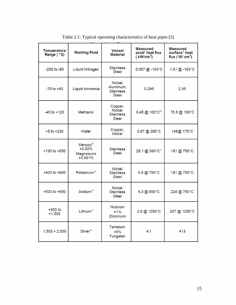
Table 2.1: Typical operating characteristics of heat pipes [5]
15

2.4.4 Material
The heat pipe material must be chemically inert with the working fluid. Any
chemical reaction will result in a by-product of noncondensible gas. Noncondensible gas
is a gas from chemical or petroleum processing units (such as distillation columns or
steam ejectors) that is not easily condensed by cooling that consists mostly of nitrogen,
light hydrocarbons, carbon dioxide, or other gaseous materials. So, the
gases will collect in the condenser end of the heat pipe, swept there by the following
vapour, and obstruct a portion of the available heat dissipation area. This in turn
degrades of heat pipes efficiency. In addition, a corrosive reaction between the envelope
and the working fluid would lead to a failure of the heat pipe’s vacuum integrity thereby
causing the heat pipe to fail. The best way is, by using water as the working fluid, the
suitable heat pipe material should be a copper. A copper-water heat pipe is the most
demonstrated heat pipe material combination in the world. Millions of units have been
building with this system and literally, millions of units per year are currently produce.
For example, Thermacore Management Solution Company from United States had
testing the material system that been demonstrated in excess of 180,000 hours of
operation with no sign of thermal degradation [8].
2.5 Heat Pipe Operation
The operation of heat pipe is depends on the each section. These sections are the
evaporator, adiabatic and condenser as in Figure 2.5. The description of the heat pipe
operation is based on the physical principles [8]. At a specific pressure conditions, two
physical principles will be occurred.
1. The first physical principles are, at a certain specific temperature, a liquid will
vaporize or turns to be vapor that will be condense. The vapor can only be condense
when the temperature at the level of saturation [8]
2. The second physical principles are, the amount of heat absorbed as a unit mass
of liquid vaporizes is equal to the amount of heat rejected at that vapor condenses. It can
16

be also be conclude that, the amount of heat absorbed at the heat supply at the evaporator
section actually is equal to the heat rejected at the section of the condenser.
The operation of heat pipe can also happen when during the capillary effect [8].
The capillary effect is the result that occurs from the capillary pressure that moves a
liquid (working fluid) in the wick inside the pipe against the gravitational field. It shows
that, the capillary effect will be operates by using the wick pumping in the heat pipe to
operates. See in Figure 2.4.
Moreover, the observation of the movement of a fluid along the channel flows
through the direction from the evaporator section to the condenser section can cause the
effects in decreasing the pressure. This axial variation of pressure is illustrated in Figure
2.3
Figure 2.3: Pressure variation along a heat pipe [7]
Figure 2.4: Schematic view and the main regions the heat pipe [4]
17

Figure 2.5: Schematic and operation of a heat pipe [8]
2.6 Heat Pipe Application in Solar Thermal Collector
There are 5 major usages of heat pipe application such as in electronics,
aerospace, heat exchangers, medicine and human body temperature control. Even though
there are various research studies, solar heating is also another example for the
application of heat pipes which is widely used nowadays. By the year of 2010 onwards,
from the global warming and environmental issues, the heat pipe solar collector is the
best solution of the renewable energy that can be applied to our daily activities [9].
The solar thermal collectors and its application are linked within the analysis of
the environmental problem that can lead to the usage of sources from the renewable
energy [10]. It comes with the usage of solar thermal collectors that had been used the
radiation energy from the sun. The main function of the solar thermal collectors is to
absorbed heat radiation from the sun and converts it to electricity. In addition, the
information includes with the brief description of various types of collectors such as flat-
plate, compound parabolic, evacuated tube, parabolic trough, Fresnel len, parabolic dish
and helistat field collectors.
From the various types of the solar thermal collector that had been listed [10], one
of the company in Canada, Solar Supply Canada Inc.® mention that the evacuated solar
collector is the main application of heat pipe technology. The main component of the
solar thermal collector which is the evacuated tube solar collector will be discussed on
the next sub-chapter.
18

2.6.1 Evacuated Tube Solar Collector
Solar Supply Canada Inc.® mentioned that, each evacuated tube collector contains
up to 30 individual glass tubes, each with an absorber plate bonded to a heat pipe. The
sample of evacuated solar collector is as shown in Figure 2.6. They are surrounded by
two glass tubes that hold a vacuum between the two tubes. The pipe transfers the heat
efficiently to a condenser through the top of the tube. The condensers are clamped to heat
exchange blocks in a well-insulated manifold. The special absorber coating absorbs more
than 92% of the arriving radiation but radiates less than 8% back to the environment as
the circulation of heat transfer process.
For the heat transfer process, it can be transferred from the absorber to the fluid
circuit which is performed by the heat pipe. A heat pipe condition is in a closed system,
evacuated and charged with a small amount of glycol before it is sealed for the usage in
the solar collector. The main function of the absorber is to impart heat to this glycol
(another type of working fluid used), which can cause it to evaporate. Meanwhile, the
steam rises to the upper end of the heat pipe where it transfers heat to the fluid circuit via
a metallic conduction bridge. Being in a dry connection, the working fluid in the heating
circuit does not flow through the collector. The heat transfer process in the evacuated
solar thermal collector shown in Figure 2.8.
Figure 2.6 Evacuated Solar Collector (with heat pipe technology) [11]
19

Moreover, in Figure 2.7 shows the glass tube contains with the absorber and heat
pipe which are mounted and sealed inside it whereby it carry the function in cutting the
heat losses via conduction and convection. Besides, within the condition of stable
vacuum, it can assure that, the collector can performed at low outside temperatures and
also protects the absorber against the environment.
Figure 2.7: Glass tube of evacuated tube collector
Figure 2.8: Heat transfer process in evacuated tube solar collector
20

Table 2.2 shows the specification of evacuated tube solar collector. Solar Supply
Canada Inc.® comes up with the details specification standard in building the tube.
Based from Table 2.2, it can gives out an idea on the operation of the tube that operates
within the certain parameter standard in order to do the heat transfer process.
Table 2.2: Evacuated Tube Solar Collector Specifications
Stand Metal gray
Tube headers Available in 10-20-25-30 (25 tube standard)
Heat pipe technology 1.2 mm copper
Maximum working temperature 99 degrees Celsius
Maximum stagnation temperature 270 degrees Celsius
Maximum working pressure 10 Bars (145 psi)
Insulation layer 50 mm polyurethane
Quality certificate ISO 9001:2000-CE
Testing certificate DIN En12975-2:2006
Length 1800 mm
Outer tube diameter 58 mm
Inner tube diameter 47 mm
Glass thickness 1.6 mm
Thermal expansion 3.3x10⁻⁶°C
Material Borosilicate Glass 3.3
Absorptive coating grading Al-N/Al
Absorptance >92% (AM 1.5)
Emittance <8% (80°C)
Vacuum P<5x10⁻³ Pa
Heat loss <0.8W/(m²°C)
Maximum strength 0.8 MPa
21

2.6.2 Heat pipe concept in evacuated tube solar collector
The heat transfer process in the evacuated tube is still the same with the heat pipe
heat transfer process. The evacuated tube that contains with the heat pipe rapidly and
efficiently transfers the captured thermal energy through the evacuated tube. Then, the
thermal energy delivered to the manifold (header) as the liquid (working fluid) boils and
rises. After the heat is removed from the heat pipe by the copper header, the liquid
condenses and gravity returns it to the base of heat pipe. It really shows that, the heat
pipe that contains in the evacuated tube solar collector, are not using the wick pumping,
but only using the gravity pumping as in conventional heat pipe operation. Finally, after
the liquid condenses and gravity pumping returns it to the base, the process is continually
repeated over and over again during the operation in absorbing the thermal energy from
the sun radiation energy as shown in Figure 2.8.
Figure 2.8: Heat pipe operates in an evacuated tube solar collector
The main function of the evacuated tube solar collector comes from the operation
of heat pipe which is located inside the glass tube. Same as previous description, it is
also a sealed hollow copper tube that contains a small amount of proprietary liquid,
which under low pressure boils at a very low temperature. For the information, the liquid
contained in the heat pipe boiling points only happens at 86 °F (30°C).
22

CHAPTER 3
METHODOLOGY
3.1 Introduction
The literature reviews had brought up some of the idea on designing the
methodology to meet the purpose of research study. Some of the journals are dealing
with the experimental study and some of it is dealing with CFD analysis. Nevertheless,
there are not less in the journals selected that are using both methods (experimental and
CFD analysis) to solve all the problem statements. According to the objectives of the
study, a proper methodology design should be made in order to make sure that to get the
successful and accurate results.
To meet the objectives, the method and design is focusing more on the qualitative
data based from actual and simulation condition. An actual condition of heat transfer
tends to be occurs when an experiment is conducted or even more in advanced techniques
of experiments. Meanwhile, the simulation conditions can be used and apply after the
physical parameters are recognized and correctly be inserted to the CFD modelling. The
collection of data need to be compared and observed to shows that all the characteristics
reliable to make the heat pipe best solution in cooling system. This can be further to
discussed in the next chapter.
23

3.2 Research Design
The first stage is it is divided into 2 sections which are the literature review and
the fabrication methods. The literature review section had gone through in the previous
chapter which contains with the field of works that comprises from various sources of
study. It is also includes with the information to suite the problem statement and purpose
of study. Meanwhile, the fabrication methods are the steps to bring up the actual model
and samples for the specimens in the parameter study. It can be used either in the
experimental, or in the CFD analysis study for comparisons of the results.
Next is the further analysis study in CFD for comparison in experimental to
obtain for both results. The important parameter studies in the experimental methods are
the temperature, T (°C) and time, t (min.). These values can be presented into a graphical
that be plotted based from the orientation angles for specimens. Finally, in the CFD
analysis study, the physical parameters such as the temperature, T (°C) and heat transfer
coefficients W/m².K are the important elements for the analysis. Besides, the analysis
study also deals with the most common boundary conditions such as inlet, outlet and
wall. These elements are further discussed. In the next pages, the research method and
design had been simplified into Figure 3.1 Flow chart of project plan.
24

REFERENCES
[1] Arul Selvan Annamalai and Velraj Ramalingam (2011), Experimental Investigation
and Computational Fluid Dynamics Analysis of A Air Cooled Condenser Heat
Pipe, Thermal Science 15 (3): 759-772.
[2] Yong Joo Park, Hwan Kook Kang, Chul Ju Kim (2002), Heat transfer characteristics
of a two-phase closed thermosyphon to the fill charge ratio, International Journal
of Heat and Mass Transfer. 45(2002): 4655-4661.
[3] Ahmet Samanci and Adnan Berber (2010), Experimental investigation of single-phase
and two phase closed thermosyphon solar water heater systems, Scientific
Research and Essays. 6(4): 688-693.
[4] M.H. Saber and H.Mazaher Ashtiani, Simulation and CFD Analysis of heat pipe heat
exchanger using Fluent to increase of the thermal efficiency, Continuum
Mechanics
[5] Holman, J.P, Heat Transfer, 5th Ed, McGraw-Hill Inc. 1981.
[6] S.B. Riffat and A. Holt, A Novel Heat Pipe/Ejector Cooler. Pergamon. 1997.
[7] P.D and D.A. Reay, Heat pipes, 4th Ed. Pergamon. 1994
[8] Yunus A. Cengel, Heat Transfer A Practical Approach. 2nd Ed New York: McGraw
Hill. 2004.
[9] Masataka Mochizuki, Thang Nguyen, Koichi Mashiko, Yuji Saito, Tien Nguyen and
Vijit Wuttijumnong (2011), A review of heat pipe application including new
opportunities, Frontiers in Heat Pipes. 2(13001): 1-2.
[10] Soteris A. Kalogirou, Solar thermal collectors and applications, Elsevier. 2004
[11] M.S. Hossain, R. Saidur, H. Fayaz, N.A. Rahim, M.R. Islam, J.U. Ahamed and
M.M. Rahman, Review on solar water heater collector and thermal energy
performance of circulating pipe, Elsevier. 2011
[12] Dhananjay Dilip Odhekar. Experimental Investigation of Bendable Heat Pipes.
M.Sc. Thesis. Auburn University; 2005.
100

[13] Daniel Harris, Qualitative Chemical Analysis, 4th Ed. W. H. Freeman and Company,
New York, pp.36; 1995
[14] Yunus A. Cengel and John M. Cimbala, Fluid Mechanics, Fundamentals and
Applications, 1st Ed. New York: McGraw-Hill Education. 2006.
[15] Saeed Moaveni, Finite Element Analysis, Theory and Application with ANSYS,
3rd Ed New Jersey: Pearson Prentice Hall. 2008.
[16] A. Nouri-Borujerdi, Performance Characteristics of A Long Heat Pipe.
[17] Versteeg, H.K., Malasekera, W. An Introduction to Computational Fluid Dynamics
The Finite Volume Method, 2nd Ed. England: Longman Limited, 2007.
[18] Salem A. Said and Bilal A. Akash, (1999). Experimental Performance of A Heat
Pipe. Pergamon, 26(5), pp.679-684.
101