analysis of alternatives non-confidential report … · analysis of alternatives . non-confidential...
TRANSCRIPT

ANALYSIS OF ALTERNATIVES
NON-CONFIDENTIAL REPORT
Legal name of applicant(s): Gerhardi Kunststofftechnik GmbH
C. Hübner GmbH
BIA Kunststoff- und Galvanotechnik GmbH & Co KG
Heinze Gruppe GmbH
Bolta Werke GmbH
Boryszew Oberflächentechnik Deutschland GmbH
WAFA Germany GmbH
Aludec Galvanic s.a.
C+C Krug GmbH
Fischer GmbH & Co. surface technologies KG
SAXONIA Galvanik GmbH
Karl Simon GmbH & Co. KG
Submitted by: Gerhardi Kunststofftechnik GmbH
Substance: Chromium trioxide, EC No: 215-607-8, CAS No: 1333-82-0
Use title: Plating on Plastics for Automotive Applications (PoPAA).
Use number: 1

ANALYSIS OF ALTERNATIVES
Use number:1 – Copy right protected – No copying / use allowed
II
CONTENTS
LIST OF ABBREVIATIONS ....................................................................................................................................... VI
GLOSSARY ................................................................................................................................................................. VIII DECLARATION .......................................................................................................................................................... IX
1. PREAMBLE ........................................................................................................................................................... 1
2. SUMMARY ............................................................................................................................................................ 2
3. INTRODUCTION .................................................................................................................................................. 7
3.1. The substance ................................................................................................................................................. 7
3.2. Uses of chromium trioxide ............................................................................................................................. 7 3.3. Purpose and benefits of the use of chromium trioxide for PoPAA ................................................................. 7
4. ANALYSIS OF SUBSTANCE FUNCTION.......................................................................................................... 9
4.1. Plastics as substrate for interior and exterior applications in the automotive industry ................................... 9
4.2. Metallic chrome coatings on plastics for the automotive industry ................................................................. 9
4.3. Process description for PoPAA....................................................................................................................... 13 4.3.1. Pre-treatment processes ........................................................................................................................ 17
Chromium trioxide etching of plastic substrates ................................................................................. 17 4.3.2. Intermediate steps (chromium trioxide free) ......................................................................................... 19 4.3.3. Chromium trioxide activation step and electroplating main treatment ................................................. 21 4.3.4. Post-treatment processes (chromium trioxide free) .............................................................................. 21
4.4. Key functionalities of PoPAA ........................................................................................................................ 21 4.4.1. Key functionalities of chromium trioxide based surface pre-treatments (etching of plastic substrates) 22 4.4.2. Key functionalities of chromium trioxide based electroplating process ............................................... 23
5. GENERAL OVERVIEW ON DEVELOPMENT AND APPROVAL PROCESSES IN THE AUTOMOTIVE SECTOR ....................................................................................................................................................................... 29
5.1. Current production parts in automotive applications - general considerations ............................................... 29
5.2. Current production parts - requirements for alternatives to metallic chrome coatings ................................... 30 5.2.1. Consideration on Implementation of Alternatives ................................................................................ 31 5.2.2. Supply chain consideration ................................................................................................................... 33
5.3. Past model service parts - - requirements for alternative metallic chrome coating......................................... 34
5.4. Conclusive remarks on credible replacement scenario in the automotive sector ............................................ 35
6. ANNUAL TONNAGE............................................................................................................................................ 38
7. IDENTIFICATION OF POSSIBLE ALTERNATIVES ......................................................................................... 39 7.1. Description of efforts made to identify possible alternatives .......................................................................... 39
7.1.1. Research and development ................................................................................................................... 39 7.1.2. Consultations ........................................................................................................................................ 40
7.2. List of possible alternatives ............................................................................................................................ 40
8. SUITABILITY AND AVAILABILITY OF POSSIBLE ALTERNATIVES ......................................................... 42
8.1. Alternatives to Cr(VI) etching pre-treatment .................................................................................................. 42 8.1.1. Pre-Treatment: Category 1 alternative: Potassium permanganate based etching solution .................... 43
8.1.1.1 Substance ID and properties / process description .................................................................. 43 8.1.1.2 Technical feasibility ................................................................................................................ 44 8.1.1.3 Economic feasibility ................................................................................................................ 45 8.1.1.4 Reduction of overall risk due to transition to the alternative ................................................... 45 8.1.1.5 Availability .............................................................................................................................. 46 8.1.1.6 Conclusion on suitability and availability for potassium permanganate based etching solution 46
ANALYSIS OF ALTERNATIVES
Use number:1 – Copy right protected – No copying / use allowed
III
8.1.2. Pre-Treatment: Category 2 alternatives ................................................................................................ 46
8.2. Alternatives to Cr(VI) electroplating main treatment ..................................................................................... 48 8.2.1. Main treatment: Category 1 alternative: Trivalent chromium electroplating ........................................ 48
8.2.1.1 Substance ID and properties / process description .................................................................. 48 8.2.1.2 Technical feasibility ................................................................................................................ 48
8.2.1.2.1 Modified process conditions and coating composition ......................................... 48 8.2.1.2.2 Performance in laboratory and field testing .......................................................... 50 8.2.1.2.3 Aesthetics ............................................................................................................. 51
8.2.1.3 Economic feasibility ................................................................................................................ 54 8.2.1.4 Reduction of overall risk due to transition to the alternative ................................................... 56 8.2.1.5 Availability .............................................................................................................................. 57 8.2.1.6 Conclusion on suitability and availability for Cr(III) .............................................................. 58
8.2.2. Main treatment: Category 1 alternative: PVD-based processes ............................................................ 59 8.2.2.1 Substance ID and properties / process description .................................................................. 59 8.2.2.2 Technical feasibility ................................................................................................................ 60 8.2.2.3 Economic feasibility ................................................................................................................ 67 8.2.2.4 Reduction of overall risk due to transition to the alternative ................................................... 69 8.2.2.5 Availability .............................................................................................................................. 69 8.2.2.6 Conclusion on suitability and availability for Alternative 2 .................................................... 70
8.2.3. Main treatment: Category 2 alternatives ............................................................................................... 71 9. OVERALL CONCLUSIONS ON SUITABILITY AND AVAILABILITY OF POSSIBLE ALTERNATIVES .. 74
REFERENCES ............................................................................................................................................................. 78
APPENDIXES .............................................................................................................................................................. 80
Appendix 1 – Matrix of customer requirements (ACEA) ....................................................................................... 81 Appendix 2 – Information on relevant substances for identified alternatives..........................................................82 Appendix 3 – OEM specifications............................................................................................................................88
ANALYSIS OF ALTERNATIVES
Use number:1 – Copy right protected – No copying / use allowed
IV
TABLES
Table 1. Summary of performance of Category 1 alternatives for PoPAA. ................................................................. 5 Table 2: The substance of this analysis of alternatives. ............................................................................................... 7 Table 3: Some specific product examples for the automotive sector. .......................................................................... 12 Table 4: Overview of intermediate pre-treatment steps. .............................................................................................. 19 Table 5: Overview on subsequent coating treatment steps for PoPAA. These steps do not comprise the use of chromium trioxide. ......................................................................................................................................................................... 20 Table 6: Key process functionalities of chromium trioxide based etching pre-treatment of plastics. .......................... 22 Table 7: Key functionalities of chromium trioxide based electroplating (the table is non-exhaustive but covers the most relevant functionalities for evaluation of potential alternatives and alternative coatings). ........................................... 24 Table 8: Time-frame for implementation of a Cr(III) plating line. .............................................................................. 32 Table 9: List of alternatives to Cr(VI) etching pre-treatment categorised. ................................................................... 41 Table 10: List of alternatives to Cr(VI) electroplating categorised. ............................................................................. 41 Table 11: Status of possible pre-treatment substitution processes. .............................................................................. 43 Table 12: Assessment of category 2 alternatives for Cr(VI) etching pre-treatment. .................................................... 46 Table 13: Results from combined Stone-chip / climate change testing. (A) Subsequent NSS (B) subsequent CASS including respective pictures. ....................................................................................................................................... 50 Table 14: Required investments (costs) for the implementation of the Cr(III) alternative. ......................................... 54 Table 15: Relative manufacturing costs for Cr(III) electroplating compared to Cr(VI) electroplating. ...................... 55 Table 16: Assessment of specific PVD-based processes developed by different companies, based on the information submitted by the companies during public consultations and tests conducted by the applicants with the respective technologies. ................................................................................................................................................................. 65 Table 17: Required investments (costs) for the implementation of the PVD alternative. ........................................... 67 Table 18: Aspects influencing process costs for the implementation of PVD compared to Cr(VI) and estimated cost trends during the review period. ................................................................................................................................... 69 Table 19: Category 2 alternatives for Cr(VI) electroplationg in PoPAA ..................................................................... 72 Table 20: Comparison of the most promising potential alternatives to PoPAA. ......................................................... 76
FIGURES
Figure 1: Typical life-time of a car model (According to VDA in FGK Chrom 2020, 2015). .................................... 3 Figure 2: Example for 2K parts. .................................................................................................................................. 10 Figure 3: Car cockpit. Red spots indicate PoPAA-parts (Source: Mercedes Benz). .................................................... 10 Figure 4: Typical application examples (VDA, FGK Chrom 2020, 2015). ................................................................. 11 Figure 5: Different 2K/3K-parts (left) PA Indoor handles (right). .............................................................................. 11 Figure 6: Multi-layer system of metallic chrome coating. *Cr(VI) involved in the process step. Scheme not true to scale. Also see Figure 7. ............................................................................................................................................... 13 Figure 7: Flow chart for the PoPAA process. Only in step 2 and step 11 Cr(VI) is used. ........................................... 14 Figure 8: Plating line for PoPAA, overview of the fully automatic production site. ................................................... 15 Figure 9: Example of a chromium bath with an exhaust system on the side. The foam film inhibits the release of exhaust aerosols and hydrogen. .................................................................................................................................... 15 Figure 10: Interior parts with metallic chrome coating on plastic substrate. ............................................................... 16 Figure 11: Coated parts on racks. Parts on racks in a serial product coating line for PoPAA. .................................... 16 Figure 12: Demounting of parts from racks. ................................................................................................................ 17 Figure 13: Illustration of etching on ABS (Häp in FGK Chrom 2020, 2015). ............................................................ 18 Figure 14: Inadequately etched surfaces compared with a successfully etched surface (over-etched = too many and too deep caverns; under-etched = not enough and too shallow caverns). ........................................................................... 18 Figure 15: The intermediate process steps between the etching and the actual Cr(VI) electroplating step are necessary to create an adhesive and conductive surface (Häp in FGK Chrom 2020, 2015). ........................................................ 19 Figure 16: Upper illustration gives an impression of selective plating on a 2K-part made of PC and ABS. The whole coating with all its layers (see Figure 6 and Section 4.3) is applied to ABS only with a smooth edge towards the PC section. Lower pictures show the casing of a centre console (left) and the casing of switches for a steering wheel (right) as examples for 2K parts. .............................................................................................................................................. 23 Figure 17: Climate control panel case treated with chromium trioxide. ...................................................................... 25 Figure 18: Left: Multifunctional car steering wheel (Skoda). Right: Hand wheel for outlet nozzles produced by plastic galvanisation. ................................................................................................................................................................ 25
ANALYSIS OF ALTERNATIVES
Use number:1 – Copy right protected – No copying / use allowed
V
Figure 19: Upper graph shows German car manufacturer strategy, with volumes in percent (Wöhrl in FGK Chrom 2020, 2013). Lower graphs show German domestic (left) and abroad (right) production of premium class cars 2002 -2014. Absolute figures in 1,000. (VDA, 2016). ............................................................................................................ 27 Figure 20: Basic structure of the automotive supply chain and role of the applicants and OEMs within it (adapted from Heneric et al. 2005 in 1.) .............................................................................................................................................. 29 Figure 21: Illustration of supply chain complexity ...................................................................................................... 30 Figure 22: Car dismantled into constituent parts (Volkswagen AG, 2013) (left). Principal engine parts of a car (HubPages, undated) (right). ......................................................................................................................................... 31 Figure 23: Typical life-time of a car model (According to VDA in FGK Chrom 2020, 2015). .................................. 32 Figure 24: EU passenger car fleet (share in % by age in 2010). Note: Information from 12 EU member states where information was available. ............................................................................................................................................ 34 Figure 25. Minimum time required for an implementation of trivalent chromium electroplating and complete elimination of Cr(VI), including time required until readiness of Cr(III) as a completely Cr(VI)-free process. Time required for further R&D is a best estimate (especially regarding the etching pre-treatment). It is not yet clear, at what pace Cr(VI) can be completely replaced by Cr(III). ..................................................................................................... 37 Figure 26: Concepts behind the two category 1 main-treatment alternatives .............................................................. 41 Figure 27: Comparison of typical etched plastic surfaces (left: after chromium trioxide etching, middle: after acidic permanganate etching, right: after alkaline permanganate etching). (Kunststoff Institut Lüdenscheid, 2014). ............ 44 Figure 28: Metallic chrome coatings derived from Cr(VI) electrolytes (left) Cr(III) electrolytes (right) (Enthone, 2015) ............................................................................................................................................................................. 50 Figure 29: Chrome coatings produced from different trivalent and hexavalent chromium based electrolytes showing the different shades of colour. Green dot: Cr(III), red dot Cr(VI) electrolyte. (Prestel in FGK Chrom 2020, 2015). ........ 52 Figure 30: Colour differences between surfaces coated with a Cr(III) electrolyte and PoPAA which is performed with a Cr(VI) electrolyte (VDA in FGK Chrom 2020, 2015). ................................................................................................ 53 Figure 31: Automotive supply chain visualising the exemplarily colour issue with Cr(III) coated parts. (VDA in FGK Chrom 2020, 2015, adapted)......................................................................................................................................... 53 Figure 32: Progress made and future Cr(III) development. ......................................................................................... 57 Figure 33: Comparison of PVD and electroplated chrome (PoPAA) regarding chemical resistance for different test patterns (FGK, 2015). ................................................................................................................................................... 61 Figure 34: PVD coated test plates after NSS. .............................................................................................................. 61 Figure 35: Comparison of PVD-chrome with electroplated Chrome. Left: electroplated chrome, right: PVD-Chrome (FGK, 2015). ................................................................................................................................................................. 64 Figure 36. Typical life-time of a car model (According to VDA in FGK Chrom 2020, 2015) ................................... 75

ANALYSIS OF ALTERNATIVES
Use number:1 – Copy right protected – No copying / use allowed
VI
LIST OF ABBREVIATIONS
ABS Acrylonitrile-Butadiene-Styrene
ABS/PC ABS with Polycarbonate
ACEA European Automobile Manufacturer Association
Acute Tox. Acute Toxicity
AfA Application for Authorisation
AiF Arbeits-gemeinschaft industrieller Forschungsvereinigungen (Federation of Industrial Cooperative Research Associations)
AoA Analysis of Alternatives
ASTM American Society for Testing Materials
Aquatic acute Hazardous to the aquatic environment (for one to four days)
Aquatic chronic Hazardous to the aquatic environment (for seven days or more)
BMBF Federal Ministry of Education and Research
Carc. Carcinogenicity
CASS Copper Accelerator Salt Spray Test
Cr(III) Trivalent Chromium, Chromium (III)
Cr(VI) Hexavalent Chromium, Chromium (VI)
CrO3 Chromium Trioxide
CSR Chemical Safety Report
CTAC Chromium Trioxide Authorisation Consortium
CVD Chemical Vapour Deposition
DIN Deutsche Industrienorm (German Organisation for industrial Standardisation)
EN European Norm
EOP End Of Production
EPA Environmental Protection Agency
EU European Union
Eye Dam. Serious eye damage
Eye Irrit. Eye irritation
FGK Fachverband Galvanisierte Kunststoffe (German Association of Electroplated Plastics)
Flam. Liq. Flammable liquid
Flam. Sol. Flammable solid
GT0/GT1 Result classification in cross-cut test
IPPC Integrated Pollution Prevention and Control
ANALYSIS OF ALTERNATIVES
Use number:1 – Copy right protected – No copying / use allowed
VII
ISO International Organization for Standardization
IUPAC International Union of Pure and Applied Chemistry
Met. Corr. Substance or mixture corrosive to metals
SDS Safety Data Sheet
Muta. Germ cell mutagenicity
NAFTA North American Free Trade Agreement
NSST Neutral Salt Spray Test
OEM Original Equipment Manufacturer
Ox. Liq. Oxidising liquid
PA Polyamide
PEI Polyetherimide
PoP Plating on Plastics
PoPAA Plating on Plastics for Automotive Applications
PVC Polyvinyl chloride
PVD Physical Vapour Deposition
REACH Registration, Evaluation, Authorisation and Restriction of Chemicals, Regulation 1907/2006, as amended
R&D Research and Development
Repr. Reproductive toxicity
Resp. Sens. Respiratory sensitisation
SEA Socio Economic Analysis
Skin Sens. Skin sensitisation
Skin irrit. Skin irritation
SOP Start Of Production
STOT SE Specific Target Organ Toxicity, Single Exposure
SVHC Substance of Very High Concern
UBA Umweltbundesamt (German Environmental Protection Agency)
UV Ultraviolet
VDA Verband der deutschen Automobilindustrie (German Automotive Industry Association)
VOC Volatile Organic Compound
ZVO Zentralverband Oberflächentechnik (Central association for surface technology)

ANALYSIS OF ALTERNATIVES
Use number:1 – Copy right protected – No copying / use allowed
VIII
GLOSSARY
Term Definition
(Potential) Alternative (Potential) Alternatives are substances or technologies assessed with regard to their suitability as substitute.
Bath The term bath refers to a typical method for surface treatment of parts. Synonymously, the terms dipping or immersion can be used.
2K/3K parts 2K/3K parts consist of 2, 3 or more different plastic materials and are manufactured by specialised moulding techniques. At least one of the applied materials cannot be treated with the PoPAA process, thus allowing selective plating.
Category 1 Alternative(s) Potential alternative(s) focused in the AoA dossier, for which relevant R&D is ongoing.
Category 2 Alternative(s) Potential alternative(s) assessed, which reveal clear technical limitations and may only be suitable for niche applications, but not as general alternative.
Controlled corrosion Controlled corrosion is a way for anticipating destructive corrosion by intentionally induced corrosion on the surface of a material. The very thin corroded layer works as a barrier that prevents further corrosion.
Current production parts Parts used in vehicle of currently produced model series.
Electroplating The term electroplating refers to the electrolytic deposition of a metal layer, here metallic chromium, by immersing the part to be plated in an electrolyte containing metal ions, appropriate anodes and applying an electrical current.
FGK Association for the representation of interests of plastics galvanising job platers. The applicants of the present AfA are members of the FGK.
Main treatment
The main treatment refers to the activation and chrome electroplating process in baths containing chromium trioxide. Thereby, the prepared (intermediate steps) surface is activated in low concentrated chromium trioxide electrolyte at very low current density and afterwards chrome coated by immersion of the part in the electrolytic plating solution.
Original Equipment Manufacturer (OEM)
Automotive manufacturers (customers of the applicants) using POPAA-parts in the production of cars.
Past model service parts Parts used in vehicle models, which are out of production.
Plating on Plastics for Automotive Applications
The Plating on Plastics for Automotive Application (PoPAA) describes a multi-step coating process, which includes the Cr(VI)-based etching pre-treatment and terminal electrodeposition of a chrome layer on plastics, most commonly Acrylonitrile-Butadiene-Styrene (ABS) and ABS in combination with Polycarbonate (PC/ABS), used for interior and exterior parts in the automotive industry.
Post-treatment Post-treatments comprise rinsing and cleaning steps to remove potential remaining process chemicals from the plated product and subsequent drying. The post-treatment is free from hexavalent chromium.
Pre-treatment
The pre-treatment refers to the chromium trioxide-based etching of plastics for the selective removal of specific amount of butadiene 1,3 (elementary component of ABS) from the surface, creating caverns serving as anchor points for the subsequent application of metal layers in the intermediate steps.
Process chain
The term process chain refers to a series of surface treatment process steps, at which the individual steps are no stand-alone processes. The individual steps form part of a higher level system and an assessment of alternatives is required to take into account the system as a whole.
PVD-based processes General term for different similar surface treatments, based on the Physical Vapour Deposition (e.g. three-layer lacquer + PVD + lacquer, or a two-layer lacquer + PVD system)

ANALYSIS OF ALTERNATIVES
Use number:1 – Copy right protected – No copying / use allowed
IX
DECLARATION
We, Gerhardi Kunststofftechnik GmbH, C. Hübner GmbH, BIA Kunststoff- und Galvanotechnik GmbH & Co KG, Heinze Gruppe GmbH, Bolta Werke GmbH, Boryszew Oberflächentechnik Deutschland GmbH, WAFA Germany GmbH, Aludec Galvanic s.a., C+C Krug GmbH, Fischer GmbH & Co. surface technologies KG, SAXONIA Galvanik GmbH, Karl Simon GmbH & Co. KG, request that the information blanked out in the “public version” of the Analysis of Alternatives is not disclosed. We hereby declare that, to the best of our knowledge as of today (February 22nd, 2016) the information is not publicly available, and in accordance with the due measures of protection that we have implemented, a member of the public should not be able to obtain access to this information without our consent or that of the third party whose commercial interests are at stake.

ANALYSIS OF ALTERNATIVES
Use number:1 – Copy right protected – No copying / use allowed
X

ANALYSIS OF ALTERNATIVES
Use number:1 – Copy right protected – No copying / use allowed
XI

ANALYSIS OF ALTERNATIVES
Use number:1 – Copy right protected – No copying / use allowed
1
1. PREAMBLE
The applicants are submitting this joint application for Plating on Plastics for Automotive Applications (PoPAA) although the use is already covered by the CTAC AfA under Use 3. Furthermore, most of the applicants are members of the CTAC consortium and contributed significantly to the development of the documents. However, the review period applied for Use 3 in the CTAC application is a compromise between the different industries sectors. Therefore, the Fachverband Galvanisierte Kunststoffe e.V. (FGK), representing most of the German PoP companies, already emphasised in the CTAC public consultation that a review period of seven years is much too short and that a review period of a minimum of twelve years would be needed because of the unique situation in the automotive sector1.
The applicant’s situation is unique because of the following reason:
1. The Automotive customers’ demand extremely strict requirements on the quality and reproducibility of the processes and products:
2. The need for planning security due to long-term demands on processes caused by the long development and life cycles of the vehicles (comparable to the aerospace industry):
3. High level of automatic production with best protection of environment and personnel.
In total, the applicants’ market share for chrome plated plastic parts used in automotive manufacturing is estimated to be 80-90 % in Germany and between 35 % and > 50 % in Europe. These figures demonstrate the strategic importance of the applicants’ production activities for the European automotive industry.
If the applicants cannot assure security of supply to the OEMs over the period of design, prototype production, serial production and repair (in average >22 years), they will lose their market in the EU as the OEMs will source chrome plated plastic parts from non-EU markets. Already today non-EU suppliers use this locational advantage to take away parts of business with lower quality demands from the suppliers located in the EU.
1 Fachverband Galvanisierte Kunststoffe (2015). Comment number 636 on review period in the public consultation of the AfA for chromium trioxide in functional chrome plating with decorative character (Consultation Number 0032-03). http://echa.europa.eu/documents/10162/18074545/a4a_comment_636_1_attachment_en.pdf (last access Feb. 2016).
ANALYSIS OF ALTERNATIVES
Use number:1 – Copy right protected – No copying / use allowed
2
2. SUMMARY
This Analysis of alternative (AoA) forms part of the application for authorisation (AfA), for the use of chromium trioxide for PoPAA. The final coated products, which are free of Cr(VI), are used in a large variety of applications in the automotive industry. The applicants, Gerhardi Kunststofftechnik GmbH, C. Hübner GmbH, BIA Kunststoff- und Galvanotechnik GmbH & Co KG, Heinze Gruppe GmbH, Bolta Werke GmbH, Boryszew Oberflächentechnik Deutschland GmbH, WAFA Germany GmbH, Aludec Galvanic s.a., C+C Krug GmbH, Fischer GmbH & Co. surface technologies KG, SAXONIA Galvanik GmbH, Karl Simon GmbH & Co. KG, in total operate 22 sites in different European countries (e.g. Germany, Spain, Slovakia, Czech Republic). The number of plastic part types produced for the automotive industry ranges between approximately xxxxxxxxxxxxxxxxxxx. In total, the applicants produce xxxxxxxxxxxxxxxxxxxxxxxxx of articles. The overall number of parts produced for the automotive industry per year at the applicants’ sites sums up to xxxxxxxxxxxx.
Plating on Plastics for Automotive Applications (PoPAA) Plastics are used as a common substrate for numerous applications due to several beneficial properties, such as weight reduction compared to metal. In the automotive sector, lower weight of the assembled car results in a lower fuel consumption and therefore less CO2 emissions. Chromium trioxide is a crucial compound of two steps of the PoPAA process.
The PoPAA process is complex and typically involves numerous steps, such as etching as pre-treatment and several intermediate plating steps followed by the chrome electroplating process (main process) itself. Chromium trioxide is only used in the etching pre-treatment and the main chrome electroplating process. The etching pre-treatment cannot be separated or individually modified without impairing the overall process and the properties of the final product. Compatibility and technical performance of the overall system are therefore considerations of primary importance for material specification.
PoPAA is performed to produce a surface that meets the high requirements predefined by the OEMs regarding functionality (e.g. being highly durable under aggressive and demanding conditions) and aesthetics (high-class, valuable, top-quality appearance). Furthermore, PoPAA is used for a selective coating of parts which are fabricated of two, three or even more plastic materials (so-called 2K- or 3K-parts). These 2K/3K parts are the result of a special moulding technique which allows the simultaneous injection of different plastic materials of which at least one component is not able to be coated with the PoPAA process. This is of particular importance to European suppliers to retain a competitive technological advantage over non-EEA suppliers, e.g. from Asia or the NAFTA countries. Over the last years the increasing demand for multicomponent applications has made this a rapidly growing market.
As of today, only the use of chromium trioxide enables the aforementioned combination of process and product specific functionalities and is further described in Section 4.4.1.
Approval and release in the automotive industry In 2014, 17.2 million cars, vans, trucks and buses were manufactured in the European Union. The European automotive industry employs 12.1 million people, including approx. 3.1 million highly skilled jobs (2012) and generates about EUR 840.5 Billion (2011). The complex automotive supply chain encompasses multiple levels of suppliers and OEMs. There are around seven tiers of suppliers within the value added chain. German OEMs in the automotive sector are recognised worldwide as a first class producer of vehicles. Over the past 12 years the premium car segment has been increasing proportionate to others and by absolute numbers. The applicants deliver the majority of their products

ANALYSIS OF ALTERNATIVES
Use number:1 – Copy right protected – No copying / use allowed
3
to European OEMs and automotive suppliers. A strong increase in the demand of chrome-plated plastic components, especially in the automotive sector, is expected in the near future. This can be explained by a general growth of the automotive market, particularly in Asian countries, and the enormous reduction of vehicle weight and thus major fuel cost savings.
Introducing new materials to the automotive market is a complex process, involving multiple phases and checks, with safety as the main driver. For any alternative to chromium trioxide, concerned components must be revalidated. Revalidation must follow the demanding requirements of the automotive industry. Importantly, requirements are defined by the OEMs instead of the platers. Over long years of development the OEMs set very high standard requirements for exterior and interior vehicle parts with which the platers have to comply.
With regard to both the highly complex nature of supply chains in the automotive industry and the lifetime of vehicles, planning security is crucial. Average life cycles of an automobile model is about 22 years, comprising 3-5 years development time, 7 years of production and at least a 10 year service life, during which there is a need to guarantee availability of spare parts (see Figure 1). Feasible changes to a vehicle model can only be made before type-approval by a certified body in the early stages of new model development.
Figure 1: Typical life-time of a car model (According to VDA in FGK Chrom 2020, 2015).
Identification of potential alternatives Chromium trioxide is used in the etching pre-treatment step and the electroplating main-treatment step of PoPAA (Section 4.3). When assessing alternatives for both steps, compatibility and technical performance of the overall systems are considerations of primary importance.
Potential alternatives for the etching of plastic as a pre-treatment are to date technically not feasible. Additional R&D is necessary to adjust the processes that create the base for the actual electroplating step to meet the industry requirements. Technically feasible alternatives for the etching of plastics are not expected to be available until 12 years after the sunset date. The most promising alternatives to Cr(VI)-based PoPAA are trivalent chromium electroplating (Cr(III) electroplating) and PVD-based processes. These two processes differ fundamentally. Trivalent chromium plating is a galvanic process similar to Cr(VI) electroplating in PoPAA. But in order to achieve a surface that can be galvanised, an etching pre-treatment is required. For that purpose currently Cr(VI) is still used. In order to develop a completely Cr(VI)-free method, a suitable alternative needs to be developed. The technology of PVD-based processes do not require any etching pre-treatment but uses a completely different coating technology.
Intensive R&D on PVD-based processes and Cr(III) electroplating has been performed over many years. Technical improvement of these potential alternatives has been achieved in recent years. As the Cr(VI)-based PoPAA is applied in a comparable galvanic process, trivalent chromium

ANALYSIS OF ALTERNATIVES
Use number:1 – Copy right protected – No copying / use allowed
4
electroplating is the main focus of current R&D efforts by the applicants; and therefore the favoured alternative. Despite major achievements, both alternatives are technically not feasible and cannot be considered available to replace chromium trioxide as a commercial application at the current stage of development. The following Table 1 summarises the limitations of the alternatives.

ANALYSIS OF ALTERNATIVES
Use number:1 – Copy right protected – No copying / use allowed
5
Table 1. Summary of performance of Category 1 alternatives for PoPAA.
Alternative Current technical and economic limitations why alternative cannot be considered as replacement for PoPAA
1
Cr(III) electroplating (including a Cr(VI)-free pre-treatment)
- Technical performance is inconsistent at the current laboratory stage. As of today, the entirety of OEMs’ requirements cannot be fulfilled;
- Despite of significant improvements, Cr(III) coated parts still show colour variations. Colour mismatch is not acceptable to the OEM or its customers. The mismatch of colours is also an issue when it comes to the replacement parts.
- Cr(VI)-free etching pre-treatment is required. An adequate Cr(VI)-free pre-treatment does not exist yet.
- Only a full conversion of the PoPAA process into a completely Cr(VI)-free treatment is regarded feasible (Qualification cycle to be passed twice).
- For metallic chrome coatings derived from Cr(III), no long-term experience regarding life-time quality exists.
- Introduction and industrialisation of Cr(III) requires significant investments in terms of process line modifications and analytics, in total, at least xxxxxxxxxxxxx and an approximate timeframe of 12 years after sunset date.
Additional time for R&D, qualification and planning is required to implement this alternative.
Results of assessment of etching with potassium permanganate (Section 8.1.1.)
Technical feasibility Economic feasibility Risk reduction Availability
Results of assessment of the Cr(III)-electroplating step (Section 8.2.1.):
Technical feasibility Economic feasibility Risk reduction Availability
2
PVD-based processes
- Technical performance of coatings derived from this technology is insufficient for several crucial parameters. As of today, the OEMs’ requirements cannot be fulfilled;
- In contrast to PoPAA coating of 2K/3K parts is not possible with PVD-based processes.
- The metal feeling (cool touch) is not available for this kind of coating and therefore the customer’s requirements connected with PoPAA are not fulfilled. The colour of these coatings much darker than that of PoPAA- or Cr(III)-parts.
- For PVD-based coatings, no long-term experience regarding life-time quality exists.
- For the applicants, a potential transition from PoPAA to PVD-based processes is accompanied by a full replacement of the existing galvanic facilities, as the process technologies differ fundamentally.
- Experience and expertise at hand at the applicants’ companies are related to galvanic processes.
- PVD could only serves as alternative for 1-10% of PoPAA-parts.
- PVD technology requires significant investments in terms of process technology, in total at least xxxxxxxxxxxxxxx. Most likely, substitution will not be achieved within 12 years after sunset date.
Due to these limitations, PVD electroplating is currently not the potential alternative favoured by the applicants.
Results of the assessment of PVD-based processes (Section 8.2.2.)
Technical feasibility Economic feasibility Risk reduction Availability
ANALYSIS OF ALTERNATIVES
Use number:1 – Copy right protected – No copying / use allowed
6
Review period Extensive evaluation of potential alternatives to chromium trioxide-based PoPAA is carried out in the present AoA. Furthermore, economic aspects, as well as aspects of approval and release in the automotive sector, are assessed with regard to a future substitution of the substance. The following key points are relevant for a derivation of the review period:
- Based on experience, and with reference to the status of R&D programs, implementation of feasible alternatives for pre-treatment and plating process for key PoPAA applications is not foreseen to be finalised within 12 years after the sunset date (Chapter 8).
- Any potential alternative is required to pass full qualification, certification and implementation/industrialisation to comply with demanding standards in the automotive sector, and the applicants’ customers (Chapter 5).
- The European automotive industry in general requires optimal framework conditions in order to maintain its competitiveness, its high technological standards and to preserve/generate jobs. Average life cycles of an automobile model is about 22 years, comprising 3-5 years of development time, 7 years of production and at least a 10 year service life, during which there is a need to guarantee availability of spare parts. With regard to both the highly complex nature of the supply chains and the lifetime of vehicles, planning reliability is crucial (Section 5.2.1.).
- Even assuming the Cr(III)-alternative (etching pre-treatment and main treatment) would be ready for implementation instantly, more than 12 years would be required until completed elimination of Cr(VI) (Chapter 5).
- The socio-economic impacts for all non-use scenarios as calculated in the SEA outweigh potential health impacts correlated with continued use of PoPAA at least by a factor of 140:1. Taking into account the worst-case exposure levels provided in the CSR and the resulting worst-case health impacts of EUR 36,409 expected per site until 2029, a long review period that allows step-wise implementation of upcoming alternatives should be granted.
As a consequence, a review period of not less than 12 years is selected because it coincides with best case estimates by the applicant of the schedule required to industrialise alternatives to chromium trioxide.

ANALYSIS OF ALTERNATIVES
Use number:1 – Copy right protected – No copying / use allowed
7
3. INTRODUCTION
3.1. The substance The following substance is subject to this Analysis of Alternatives (AoA) (Table 2).
Table 2: The substance of this analysis of alternatives.
Substance Intrinsic property(ies)1 Latest application date² Sunset date³
Chromium trioxide
EC No: 215-607-8
CAS No: 1333-82-0
Carcinogenic (category 1A)
Mutagenic (category 1B)
21 March 2016 21 September 2017
1 Referred to in Article 57 of Regulation (EC) No. 1907/2006 ² Date referred to in Article 58(1) (c) (ii) of Regulation (EC) No. 1907/2006 3 Date referred to in Article 58(1) (c) (i) of Regulation (EC) No. 1907/2006
Chromium trioxide is categorised as a substance of very high concern (SVHC) and is listed on Annex XIV of Regulation (EC) No 1907/2006. When brought in contact with water, chromium trioxide (EC No 215-607-8) forms two acids and several oligomers: Chromic acid (EC No 231-801-5), Dichromic acid (EC No 236-881-5), oligomers of chromic acid and dichromic acid (further referred as "Chromic acids and their oligomers"). This AoA discusses many situations where this is the case. For the purpose of this document the term chromic acid is synonymous with a mixture containing chromium trioxide and water.
3.2. Uses of chromium trioxide The main uses of chromium trioxide within Plating on Plastics for Automotive Applications (PoPAA) automotive applications are:
- Pre-treatment processes: etching of plastic substrates; and - Electroplating: applying a metallic chrome coating on top of plastic substrates, creating
either a bright (shiny) or matte look. In the serial production of PoPAA-parts 60 – 70 different articles are manufactured at once. Both process steps are obligatory, as electroplating is not possible without the preceding pre-treatment step regardless of the electroplating technique. The chromium metallic layer deposited in a part or article after PoPAA is completely free of Cr(VI).
The applicants, Gerhardi Kunststofftechnik GmbH, C. Hübner GmbH, BIA Kunststoff- und Galvanotechnik GmbH & Co KG, Heinze Gruppe GmbH, Bolta Werke GmbH, Boryszew Oberflächentechnik Deutschland GmbH, WAFA Germany GmbH, Aludec Galvanic s.a., C+C Krug GmbH, Fischer GmbH & Co. surface technologies KG, SAXONIA Galvanik GmbH, Karl Simon GmbH & Co. KG, in total operate 22 sites in different European countries (e.g. Germany, Spain, Slovakia, Czech Republic).The number of different types of plastic parts produced for the automotive industry per site ranges between approximately xxxxxxxxxxxxx. In total, the applicants produce more than xxxxxxxxxxxxxxxxxxx articles.
3.3. Purpose and benefits of the use of chromium trioxide for PoPAA Using chromium trioxide has multifunctional positive effects based on the characteristics of the Cr(VI) compound. The following general desirable properties of coatings produced from chromium

ANALYSIS OF ALTERNATIVES
Use number:1 – Copy right protected – No copying / use allowed
8
trioxide have made this compound a state of the art substance for a wide range of applications for more than 50 years. As of today, only the use of chromium trioxide enables this combination of process and product specific functionalities that are essential to fulfil the demanding requirements of the automotive industry. Longevity and long life-cycles due to classic designs of the final products based on the following Cr(VI)-based key properties:
- Excellent corrosion protection and chemical resistance in a wide range of environments that guarantees the high-quality appearance over long product life-cycles;
- Wear and abrasion resistance; - Excellent Adhesion between coating and substrate in order to prevent damage of the surface
by cracks and/or blistering; - Resistance to temperature change and heat (e.g. fast temperature changes inside a car during
summer or winter time due to air conditioning/heater) to preserve the coatings from damages and cracks;
- A high-class surface with favourite bluish colour and mirror-like reflection or aluminium-like matt surfaces;
- Haptic properties corresponding to metal parts, so-called cool touch effect; - Prevention of nickel leaching; and - Hardness, scratch resistance.
Furthermore, PoPAA offers additional economic, environmental and sustainability advantages to the automotive sector:
- Many kinds of articles, all with different geometries (flat, complex, with inner cavities, etc.) and sizes (independently if small or big), as well as more-component parts (2K/3K), can be plated;
- Plastics as a base material have an immense cost and energy consumption advantage over full-metal parts;
- Parts of any size and form can be easily produced by injection moulding with sufficient geometric complexity;
- In contrast to plastic parts, some metal parts have to be mechanically reworked before chromium treatment;
- Weight benefit compared to metal parts contributes to a reduction of fuel consumption and corresponding CO2-emissions;
- Chromium coated surfaces have high acceptance in the automotive industry; they are considered to be long-lasting and high-quality. Life-time of the parts would be reduced when using other surface coating techniques that result in coatings of lower quality; and
- Chromium coated plastic parts in the automotive sector can typically not be considered as disposal articles because of the corresponding life-time of the automobile in which they are assembled.
Several alternatives are being tested to replace chromium trioxide. It is a challenge to find a substitute which meets all requirements of each product and specific application while also being technically and economically feasible.
ANALYSIS OF ALTERNATIVES
Use number:1 – Copy right protected – No copying / use allowed
9
4. ANALYSIS OF SUBSTANCE FUNCTION
In order to be able to assess possible alternatives to chromium trioxide for PoPAA, the following sections provide background information on the industrial applications chromium trioxide is used in; the properties and parameters which provide the desired functioning.
In Section 4.1 and 4.2 a general overview of the base materials, surface properties and several product examples are provided. For a better understanding of the process as a whole, Section 4.3 describes the various steps of an electroplating line.
Section 4.4 elaborates on the necessary key requirements for the final products for the automotive industry derived by chromium trioxide based surface treatment. These requirements serve as a basis for the assessment of alternatives described in Chapter 8.
For a brief introduction to PoPAA, a short video (about 5 minutes) is available on one applicants´ homepage: http://bia-kunststoff.de/index.php/en/company?view=featured.
4.1. Plastics as substrate for interior and exterior applications in the automotive industry Chromium trioxide is a crucial component of process solutions in two steps of the electroplating process of plastics. The final metallic product, which is free of Cr(VI), is used in a large variety of applications in the automotive industry. The industry relies on the use of different kinds of plastic substrates. The most commonly used plastic substrates for automotive applications are:
- ABS (acrylonitrile-butadiene-styrene); - PC/ABS (ABS with polycarbonate).
PA (Polyamide) blended with 40 % mineral filler is a plastic substrate which is less commonly used and only for special applications due to its specific material properties (high tensile strength: for example, well suited for the door handles in the interior of cars).
In the subsequent sections, the term “plastic substrates” is used, and given no further specification, all of the above mentioned types of substrates are implied. If there are technical constraints or limitations to a specific kind of substrate, it is indicated in the respective paragraphs.
Plastics are used as a common substrate for numerous applications due to several beneficial properties. The low specific weight of the substrate for example reduces the overall weight of the assembled product. In the automotive sector, lower weight of the assembled car results in a lower fuel consumption and therefore less CO2 emissions. In addition, production of plastic parts is easily carried out by injection moulding. This also allows new technical solutions for new technologies in cars. In order to make use of these benefits for exterior and interior vehicle components, the plastic piece needs to be protected from various environmental impacts. This is achieved by applying a protective layer onto the plastic surface. In this context metal coating provides the most resistant protection.
4.2. Metallic chrome coatings on plastics for the automotive industry PoPAA is usually performed to create a surface that meets the high requirements that are predefined by the Original Equipment Manufacturers (OEMs) regarding functionality (e.g. being highly durable under aggressive and demanding conditions) and aesthetics (high-class, valuable, top-quality appearance). A detailed matrix of the requirements of the European automotive industry is shown in the confidential Appendix 1 (ACEA, 2014). The separately submitted confidential Appendix 3 shows exemplarily how complex and detailed the OEM specifications are. The most critical requirements for the assessment of alternatives are described and illustrated in Section 4.4.

ANALYSIS OF ALTERNATIVES
Use number:1 – Copy right protected – No copying / use allowed
10
The vast majority of finishes show a bright or matt silvery appearance. Chrome plated surfaces serve as a very important classic (interior and exterior) design element of vehicles, not only for OEMs in the premium car sector. Chrome plated surfaces are widely accepted as a synonym for high-class surfaces which play a crucial role in the commercial success of vehicles.
PoPAA is also a valuable technology applied for a selective coating of parts that are fabricated of two, three or more plastic materials (so-called 2K- or 3K-parts). These 2K/3K parts are the result of a special moulding technique which allows for the simultaneous injection of different plastic materials, of which at least one component is not able be coated with the PoPAA process. Only the material parts that can be coated are available for the subsequent plating. The resulting product is a single part, only partially coated, with several functional areas, for instance, illuminable control buttons (as depicted in Figure 2) or adjusting wheels for ventilation nozzles (Figure 18).
Figure 2: Example for 2K parts.
PoPAA is mandatory for these applications as it guarantees the unique combination of high quality, longevity and long life-cycles of the final products together with high-value aesthetics and classical design features. Typical product examples are provided in Figure 3 and Figure 4 below; as well as in Table 3.
Figure 3: Car cockpit. Red spots indicate PoPAA-parts (Source: Mercedes Benz).

ANALYSIS OF ALTERNATIVES
Use number:1 – Copy right protected – No copying / use allowed
11
Figure 4: Typical application examples (VDA, FGK Chrom 2020, 2015).
Figure 5: Different 2K/3K-parts (left) PA Indoor handles (right).

ANALYSIS OF ALTERNATIVES
Use number:1 – Copy right protected – No copying / use allowed
12
Table 3: Some specific product examples for the automotive sector.
Exterior Interior
Brand labels/ornaments Brand labels/ornaments
Trim strips Gear lever knobs
Rims Trim strips
Front skirts Decorative frames
Exterior rear-view mirrors Rear-view mirrors
Radiator grills Door opener
Door opener Switches and knobs for electronic devices (radio, climate control, seat heating, window opener etc.)
Trims Emblems
Frames Steering wheel cover
Rings Steering wheels knobs (menu control)
Emblems 2K-/3K-component parts, selective plating: adjustment wheels, rotary knobs, knurls, push buttons, haptic ribs
Logos 1K component parts: Trims, frames, rings, caps, emblems, logos
Fuel filler caps Polyamide: Indoor handles
The metallic chrome layer is applied as final coating on top of a multi-layer system. The combination of intermediate layers is responsible for the final colour of the top coating as well as the corrosion properties. The intermediate layers vary depending on the required functionalities of the final product and the substrate used. Figure 6 provides an overview of conventional multi-layer systems for automotive applications. Briefly, the lowermost layer is the plastic substrate that has been prepared by etching to achieve the cavern structure on which the intermediate layers, comprising several copper and nickel layers with different thicknesses, are applied. The thin layer on top is the chromium layer. For more detailed information on the key functionalities the coating provides, the reader is referred to Section 4.4.

ANALYSIS OF ALTERNATIVES
Use number:1 – Copy right protected – No copying / use allowed
13
Figure 6: Multi-layer system of metallic chrome coating. *Cr(VI) involved in the process step. Scheme not true to scale. See also Figure 7.
4.3. Process description for PoPAA A general process description is presented in the following. The PoPAA encompasses several mandatory steps forming the typical process chain for this application.
In the first process step, the surface of the substrate is chemically pre-treated using chromium trioxide. A functional metal multi-layer system is then applied by electroplating. The final layer is a metallic chrome coating deposited by chromium trioxide-based electroplating. After the plating steps, adequate post-treatment steps are carried out, such as rinsing, reduction and drying. Importantly, the use of chromium trioxide is critical for two different process steps:
- the etching pre-treatment step; and - the chrome electroplating process.
Only the combination of adequate pre-treatment, main process step and post-treatment will lead to a well-finished surface providing all necessary key requirements for the respective applications in the automotive sector. Consequently, when assessing alternatives to chromium trioxide-based PoPAA, the whole process chain and the performance of the end product has to be taken into account.
The electroplating process chain with serial wet-in-wet processes is illustrated in the flow process chart in Figure 7. The process steps 2-12 are carried out on fully automated systems, as illustrated exemplarily in the following Figure 8-Figure 11.

ANALYSIS OF ALTERNATIVES
Use number:1 – Copy right protected – No copying / use allowed
14
Figure 7: Flow chart for the PoPAA process. Only in step 2 and step 11 Cr(VI) is used.
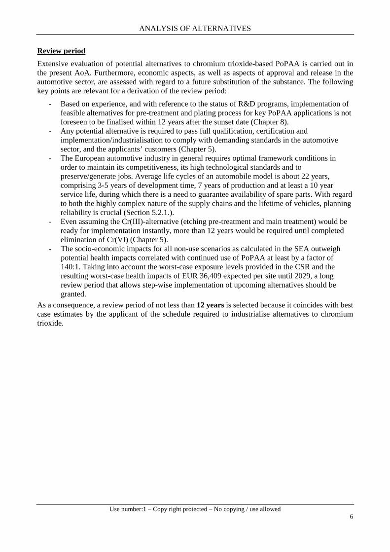
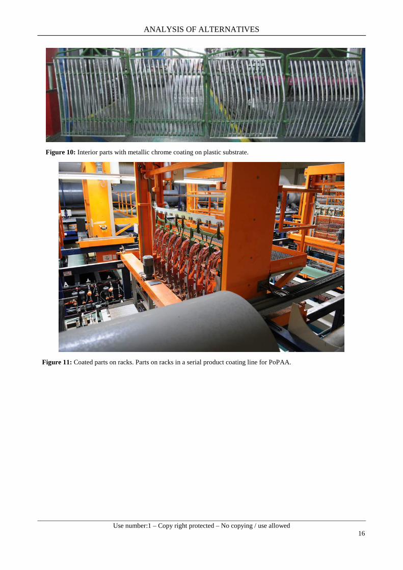
Company specific and sector specific adaptions to the general process description presented above are the rule rather than the exception. All process steps are performed by dipping the substrates in a bath containing the process step specific aqueous solution. It is an automated serial wet-in-wet process, without intermediate storage of products at any time, except for the final drying step. Numerous rinsing steps are performed along the process chain to prevent the carry-over of substances from one bath into another, which would otherwise lead to interference with the subsequent process step. For the coating process the parts are attached to racks (Figure 10-Figure 12) by hand in a labour-intensive procedure. On these racks the parts are moved from one bath to another during the serial production of PoPAA. Importantly, the racks together with the attached parts form the cathode in the galvanic process.

ANALYSIS OF ALTERNATIVES
Use number:1 – Copy right protected – No copying / use allowed
15
Figure 8: Plating line for PoPAA, overview of the fully automatic production site.
Figure 9: Example of a chromium bath with an exhaust system on the side. The foam film inhibits the release of exhaust aerosols and hydrogen.
ANALYSIS OF ALTERNATIVES
Use number:1 – Copy right protected – No copying / use allowed
16
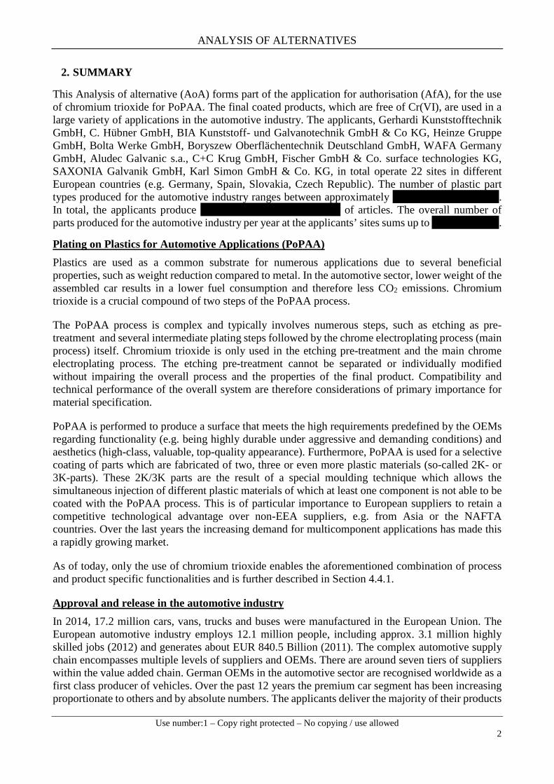
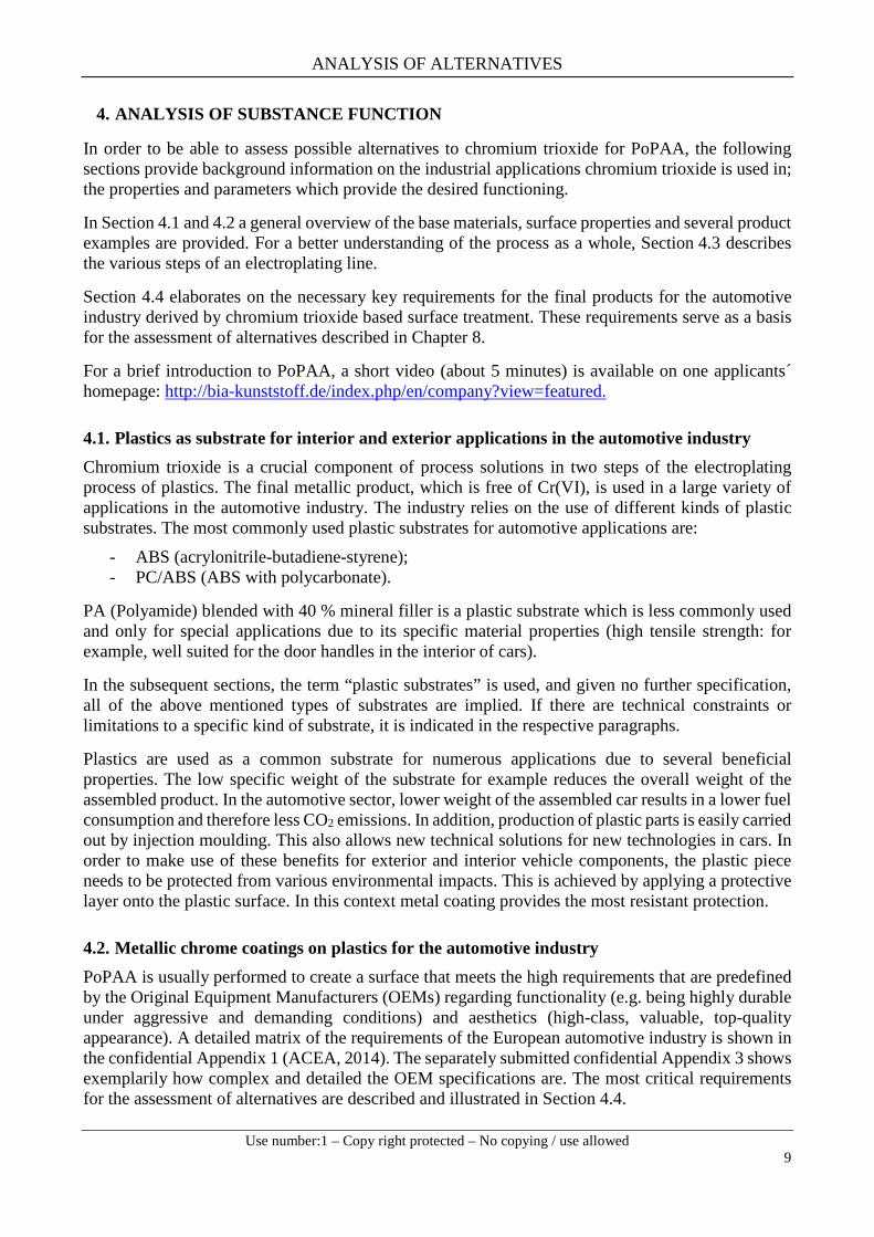
Figure 10: Interior parts with metallic chrome coating on plastic substrate.
Figure 11: Coated parts on racks. Parts on racks in a serial product coating line for PoPAA.

ANALYSIS OF ALTERNATIVES
Use number:1 – Copy right protected – No copying / use allowed
17
Figure 12: Demounting of parts from racks.
The following sections describe in more detail the process steps where chromium trioxide is used. In-depth descriptions of the key performance parameters and the sector specific minimum requirements are provided in Section 4.4.
4.3.1. Pre-treatment processes Adequate preparation of the base substrate is a prerequisite of the process: adhesion between coating and substrate depends on the force of attraction at a molecular level. Therefore, the surface of the substrate must be absolutely free of contaminants, corrosive products and other foreign material until the coating process is finished. The parts to be treated are fixated on a rack. The rack is designed to allow all inside and outside areas of the parts to be in contact with the respective bath solution. Later on, the rack together with the fixated parts serves as cathode during the galvanic processes. Sacrificial anodes, or inert anodes, are used. The rack and the substrate are immersed in the electrolytic plating solution containing the dissolved cations and anions (electrolyte).
As the first step, chromium trioxide based process etching of the plastics, as described below, is mandatory.
Chromium trioxide etching of plastic substrates Etching is generally performed and integrated in the whole plating process. Etching of plastic substrates with a chromium trioxide containing solution creates a rough surface by removing the butadiene component from the substrate. Details of the process are given below, using the most commonly used plastic substrate ABS as an example. The pre-treatment is a pre-requisite for:
- sufficient adhesion between plastic substrate and the deposited metal layers; and - a conductive surface on the plastic substrate.

ANALYSIS OF ALTERNATIVES
Use number:1 – Copy right protected – No copying / use allowed
18
During the etching process, a specific amount of butadiene 1,3 (elementary component of ABS) is removed selectively from the surface, creating caverns that act as contact points (anchor points) for the subsequent metal layers (Figure 13 and Figure 14). For the required quality of the final metallic chrome coating, adequate depth and count of caverns is crucial.
Figure 13: Illustration of etching on ABS (Häp in FGK Chrom 2020, 2015).
Figure 14: Inadequately etched surfaces compared with a successfully etched surface (over-etched = too many and too deep caverns; under-etched = not enough and too shallow caverns).
Inadequate etching, as exemplified in Figure 14, can cause two major failures: not enough and too shallow caverns (under-etching), or too deep and too many caverns (over-etching). Both failures are not acceptable as they lead to a poor and insufficient adhesion of the subsequently applied intermediate layers and the final metallic chrome coating. These effects may occur when etching time, bath temperature and/or concentration of oxidising chemicals in the etching bath are insufficient.
For the etching of plastic substrates, an acidic oxidative mixture of chromium trioxide (between 350 and 400 g/l CrO3) and sulphuric acid (around 400 g/l H2SO4) is used. The etching process is operated at temperatures between 68° to 70°C and lasts for approximately 10-12 minutes (Berndt, 2011).
Surface after successful etching
Over-etched surface
Under-etched surface

ANALYSIS OF ALTERNATIVES
Use number:1 – Copy right protected – No copying / use allowed
19
Besides creating caverns on the plastic surface, the surface of the substrate is cleaned simultaneously from minor impurities. Additionally, the surface becomes hydrophilic, in the sense of being wettable by aqueous solutions.
All of these functionalities are indispensable for the following processes to achieve the quality demands of the whole chrome plating process.
During the etching process, the Cr(VI) ions in the etching solutions are reduced to Cr(III) ions. For sustainability reasons, the etching solution is regenerated in the so called “Oxamat” bath resulting in a re-oxidising of Cr(III) to Cr(VI). This measure limits the need for topping-off the chromium trioxide based etching solution. Topping-off is only needed to cover losses by protraction effects from the etching bath to the subsequent rinsing bath and for any evaporation effects. The etched part itself is free of Cr(VI) due to the subsequent reduction and rinsing steps.
4.3.2. Intermediate steps (chromium trioxide free) Different intermediate steps are undertaken after etching prior to the subsequent coating steps to activate the plastic substrate and to prepare the surface for the adhesive bonding of the subsequent metal coating. These steps are summarised in Table 4 below.
Table 4: Overview of intermediate pre-treatment steps.
Treatment step Purpose
Treatment with bis(hydroxylammonium)sulphate (H8N2O6S)
- Reduction of remaining Cr(VI) ions on the surface to Cr(III)
Treatment with hydrochloric acid (HCl) - Preparation of subsequent activation step
Activation with colloidal tin / palladium solution (acidic hydrogen chlorine based)
- Adsorption of palladium in the caverns - Preparing the surface for the subsequent electroless nickel plating.
Acceleration solution comprising a reducing agent
- Removal of the protective colloidal tin chloride layer. - Activated palladium surface (Fath, 2008).
Figure 15 illustrates the idea behind the intermediate steps of preparing the etched surface for the actual Cr(VI) coating top-layer.
Figure 15: The intermediate process steps between the etching and the actual Cr(VI) electroplating step are necessary to create an adhesive and conductive surface (Häp in FGK Chrom 2020, 2015).
Table 5 provides an overview on the subsequent steps before electroplating with chromium trioxide. The reader should note that these steps do not include the use of chromium trioxide.

ANALYSIS OF ALTERNATIVES
Use number:1 – Copy right protected – No copying / use allowed
20
Table 5: Overview on subsequent coating treatment steps for PoPAA. These steps do not comprise the use of chromium trioxide.
Process step Purpose
Electroless nickel plating
The conductivity of the activated plastic surface is locally enhanced following the treatment of the caverns. However, this is not sufficient to generate enough adhesion for subsequent metallic layers (Fath, 2008). Therefore, an electroless nickel plating is performed to enhance the whole substrate surface. During this process a thin nickel layer with a thickness between 0.1 to 0.5 µm is applied by auto-catalytic deposition. This creates an overall initial metallic layer on the plastic substrate. The plastic part is now conductive and prepared for the following electrochemical process and provides the adhesive properties that are required for subsequent layers.
Electrochemical Initial nickel or copper layer
The metallic layer thickness and electrical conductivity must be increased by applying either an initial copper layer (copper strike or copper immersion) or an initial nickel layer (nickel strike). The galvanic effect causes dissolution of the nickel and deposition of the copper onto the substrate (electroless step). In both cases, the resulting copper layer enhances the conductivity of the base substrate and protects it from corrosion during the subsequent copper plating step.
Copper step The copper layer serves as a ductile buffer between the soft plastic and the subsequent metal layers made of nickel and chrome with increasing hardness. Copper is the main metallic layer (15 – 40 µm) and is much thicker than the chromium layer (0.15 – 1 µm). The copper equalises tensions resulting from different coefficients of expansion of the different materials occurring in the course of temperature differences and temperature changes. The copper layer prevents cracks and blistering or delamination of the subsequent coatings.
Nickel step The application of nickel layers prior to the final metallic chrome layer is necessary, as only the multi-layer combination is able to meet the required key functionality of the final product. These are corrosion and chemical resistance, hardness, adhesion and high aesthetic value (top-quality appearance) of the final product. The last nickel layer as such characterises the final appearance of the product as matt, satin or bright and is also applied in a two-layer system. It combines either semi-bright nickel layer and bright nickel layer or functional nickel layer or velour nickel layer.
Functional nickel step – optional
Depending on the application, different kinds of functional nickel layers, can be applied on top of the described two-layer nickel system, enhancing the corrosion protection of the substrate. The micro cracked nickel layer is applied under high tensile stress. After the application of the final metallic chrome layer and a subsequent hot rinsing, micro cracks occur forming a very thin network affecting the metallic chrome layer as well as the functional micro cracked nickel layer. This network formation is a desired effect and a substantial part of the corrosion protection system, since a controlled corrosion attack is generally preferred compared to local corrosion attacks or single macro cracks. The development of micro cracks can be controlled by reduced electric current and enhanced bath temperature. Depending on the process conditions, a conventional process results in between 400 - 800 micro cracks per centimetre, while a forced micro cracked process creates about 2000 micro cracks per centimetre. A microporous nickel layer with integrated inert particulate matter is applied by the same mechanism as for micro cracked nickel, but with a reduced electrical current. This layer is applied to enhance the potential output between the underlying bright nickel layer and the subsequent metallic chrome coating, which leads to an enhanced corrosion protection. The microporous nickel has to comprise more than 10000 active pores per square centimetre.
ANALYSIS OF ALTERNATIVES
Use number:1 – Copy right protected – No copying / use allowed
21
4.3.3. Chromium trioxide activation step and electroplating main treatment Prior to the actual chrome plating process, the deposited nickel surface must be activated by using a low concentrated chromium trioxide electrolyte at a very low current density.
The substrate is immersed in the electrolytic plating solution containing dissolved chromium trioxide and additives (electrolytes). During the electroplating process, Cr(VI) is reduced to metallic chrome and builds up the metallic chrome coating (electrodeposition). The required thickness of the metallic chrome layer is sector specific and depends on the respective product and corresponding applications, but is typically in the range between 0.15 to 1.0 µm. The bright chrome appearance of the product with its slightly bluish cool character is solely a result of the chromium trioxide based electroplating.
During the chrome electroplating process chain, numerous rinsing steps are carried out to prevent the drag-out of substances from one plating bath to the next. Rinsing is commonly performed by dipping the product in a bath filled with clean rinsing water. It is usually conducted in several steps following the cascade technology. The most common technique is counter-current cascade rinsing, for which the part is rinsed in a succession of rinsing baths, which are dedicated to the plating bath. Most of the process water is handled in a closed-loop system minimising wastewater streams by reusing rinsing water in another process bath of the same type. Refilling of the chromium trioxide electrolyte is always performed at the same bath. A reduction step to reduce the remaining Cr(VI) to Cr(III) after each chrome process (see step 2 and 6 in Fig. 6) is a mandatory component of the plating line.
Overall, the electrolytic process of plating with chromium trioxide offers several advantages. The process is robust and is performed at low temperatures (low energy costs for heating of the bath). The coating is applied quickly; and due to the bath application technique, almost any kind of articles of variable geometry (flat, complex, with inner cavities, etc.) and size (independently if small or big) can be plated.
4.3.4. Post-treatment processes (chromium trioxide free) Post-treatments comprise rinsing, reduction and cleaning steps to remove any potentially remaining process chemicals from the plated product. In a final step the product is dried. These post-treatments are free from chromium trioxide and differ depending on the base substrate and the company or sector specific requirements. The final appearance of the metallic chrome coated parts is illustrated in Figure 10. The final chrome coated parts consist of metallic chrome and are free of Chrome (VI).
4.4. Key functionalities of PoPAA The unique functionalities of chromium trioxide make it an ideal substance in PoPAA, and not easily replaced. The following sections introduce key functionalities of the etching pre-treatment and the main electroplating step based on chromium trioxide. As of today, only the use of chromium trioxide offers the combination of process and product specific functionalities that are needed to fulfil the demanding requirements of the automotive industry. Importantly, these requirements are predefined by the automotive OEMs, who appreciate the high-quality of chrome-plated surfaces. Moreover, the demand for PoPAA-parts has been steadily increasing over the past years. This is because of the rising demand for European cars and their world-leading design, where these parts play a central role - not only in the premium car segment, but also in the other classes.
ANALYSIS OF ALTERNATIVES
Use number:1 – Copy right protected – No copying / use allowed
22
4.4.1. Key functionalities of chromium trioxide based surface pre-treatments (etching of plastic substrates)
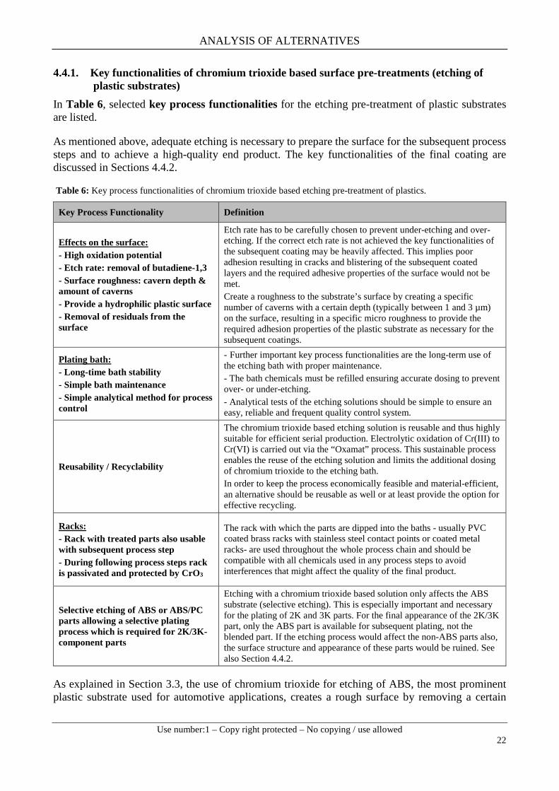
In Table 6, selected key process functionalities for the etching pre-treatment of plastic substrates are listed.
As mentioned above, adequate etching is necessary to prepare the surface for the subsequent process steps and to achieve a high-quality end product. The key functionalities of the final coating are discussed in Sections 4.4.2.
Table 6: Key process functionalities of chromium trioxide based etching pre-treatment of plastics.
Key Process Functionality Definition
Effects on the surface: - High oxidation potential - Etch rate: removal of butadiene-1,3 - Surface roughness: cavern depth & amount of caverns - Provide a hydrophilic plastic surface - Removal of residuals from the surface
Etch rate has to be carefully chosen to prevent under-etching and over-etching. If the correct etch rate is not achieved the key functionalities of the subsequent coating may be heavily affected. This implies poor adhesion resulting in cracks and blistering of the subsequent coated layers and the required adhesive properties of the surface would not be met. Create a roughness to the substrate’s surface by creating a specific number of caverns with a certain depth (typically between 1 and 3 µm) on the surface, resulting in a specific micro roughness to provide the required adhesion properties of the plastic substrate as necessary for the subsequent coatings.
Plating bath: - Long-time bath stability - Simple bath maintenance - Simple analytical method for process control
- Further important key process functionalities are the long-term use of the etching bath with proper maintenance. - The bath chemicals must be refilled ensuring accurate dosing to prevent over- or under-etching. - Analytical tests of the etching solutions should be simple to ensure an easy, reliable and frequent quality control system.
Reusability / Recyclability
The chromium trioxide based etching solution is reusable and thus highly suitable for efficient serial production. Electrolytic oxidation of Cr(III) to Cr(VI) is carried out via the “Oxamat” process. This sustainable process enables the reuse of the etching solution and limits the additional dosing of chromium trioxide to the etching bath. In order to keep the process economically feasible and material-efficient, an alternative should be reusable as well or at least provide the option for effective recycling.
Racks: - Rack with treated parts also usable with subsequent process step - During following process steps rack is passivated and protected by CrO3
The rack with which the parts are dipped into the baths - usually PVC coated brass racks with stainless steel contact points or coated metal racks- are used throughout the whole process chain and should be compatible with all chemicals used in any process steps to avoid interferences that might affect the quality of the final product.
Selective etching of ABS or ABS/PC parts allowing a selective plating process which is required for 2K/3K-component parts
Etching with a chromium trioxide based solution only affects the ABS substrate (selective etching). This is especially important and necessary for the plating of 2K and 3K parts. For the final appearance of the 2K/3K part, only the ABS part is available for subsequent plating, not the blended part. If the etching process would affect the non-ABS parts also, the surface structure and appearance of these parts would be ruined. See also Section 4.4.2.
As explained in Section 3.3, the use of chromium trioxide for etching of ABS, the most prominent plastic substrate used for automotive applications, creates a rough surface by removing a certain

ANALYSIS OF ALTERNATIVES
Use number:1 – Copy right protected – No copying / use allowed
23
amount of the butadiene component from the substrate. The higher the butadiene content of the substrate, the more caverns are created. Activation of the surface is performed by using a colloidal Tin / Palladium solution. This colloid has a strong electronegative charge, which is opposite to that of ABS, leading to absorption of palladium into the caverns of the etched surface. Palladium serves as a catalyst for the subsequent layers; the higher the palladium content, the more active the surface. In the case of 2K or 3K parts, the substrate that is to remain uncoated (e.g. PC) must not be activated (see Figure 16).
Figure 16: Upper illustration gives an impression of selective plating on a 2K-part made of PC and ABS. The whole coating with all its layers (see Figure 6 and Section 4.3) is applied to ABS only with a smooth edge towards the PC section. Lower pictures show the casing of a centre console (left) and the casing of switches for a steering wheel (right) as examples for 2K parts.
4.4.2. Key functionalities of chromium trioxide based electroplating process This section presents the key functionalities for PoPAA. Most importantly, only the use of chromium trioxide offers this combination of process and product specific functionalities that are needed to fulfil the demanding industry requirements and customer expectations. A detailed matrix of the requirements including the relevant product specifications of the European automotive industry is shown in the confidential Appendix 1 (ACEA, 2014). Additionally, the separately submitted confidential Appendix 3 shows exemplarily how complex and detailed the OEM specifications are. These requirements are set by the OEMs and need to be fulfilled by the applicants that serve as important players in different tiers of the supply chain. Table 7 gives an overview on the key functionalities for PoPAA, of which some are described in more detail below.
ABSPCPC ABS

ANALYSIS OF ALTERNATIVES
Use number:1 – Copy right protected – No copying / use allowed
24
Table 7: Key functionalities of chromium trioxide based electroplating (the table is non-exhaustive but covers the most relevant functionalities for evaluation of potential alternatives and alternative coatings).
Key Functionality Definition / Justification Automotive exterior Automotive interior
Corrosion resistance
Most critical parameter, meeting its minimum requirements play a key role to assure the required life time of automotive parts whilst preserving the functionality and aesthetics of the plated parts over long-term.
- 480 h NSST EN ISO 9227 (up to 1000 h). - Up to 96 h CASS EN ISO 9227. - Numerous tests acc. to OEM specifications, such as Florida or Kalahari simulation, Kesternich test.
- 240 h NSST EN ISO 9227. - 24 h CASS EN ISO 9227.
Chemical resistance (resistance against cleaning agents)
Resistance against cleaning agents, that is, the resistance against corrosion after contact with aggressive agents, is one of the performance parameters of highest priority in the automotive industry.
- Specific OEM tests: No visual degradation of the coating after testing with different chemicals.
- Specific OEM tests: No visual degradation of the coating after testing with different chemicals.
Wear resistance / abrasion resistance (scratch resistance)
Abrasion / wear resistance of a coating defines its ability to resist the gradual wearing caused by abrasion and friction.
- Taber line abrasion: 80 % remaining gloss after 20 double strokes EN 2813. - Car wash resistance ISO 20566.
- Taber abrasion: 10,000 hubs (10 N) - Further tests acc. to OEM specifications, for example Abrex or Martindale.
Ni leaching (not toxic)
Certain amounts of nickel may leach out from the multi-layer coating surface in contact with skin. As nickel is an allergen this is to be avoided.
- - 30 µg/cm² per day (DIN1811, OEM specific requirement.
Adhesion
Coatings of exterior parts can be exposed to harsh environmental conditions, while interior coatings are exposed to a large variety of chemicals and reagents. For the required life time and first-class aesthetic appearance the coatings must withstand these effects.
- GT0 to GT1 (after temperature cycle test) in cross-cut test EN ISO 2409. Peel resistance: > 3.5 N/cm to 9 N/cm (ABS: 7 N/cm). - Stone-chip resistance is tested via a strip tape test according to EN ISO 20567-1. - Numerous tests according to OEM specifications.
- GT0 to GT1 (after temperature cycle test) in Cross-cut test EN ISO 2409. Peel resistance: > 3.5 N/cm to 9 N/cm (ABS: 7 N/cm). - Numerous tests acc. to OEM specifications.
Sunlight resistance (UV exposure)
Long term sunlight exposure can cause UV degradation resulting in cracks and blistering of the coating.
- 3200 h Florida simulation. - 10 exposure cycles according to ISO 75202.
Temperature change resistance / heat resistance
The base material (e.g. ABS) and intermediate layers (such as copper layer or nickel layer) are characterised by individual thermal behaviour and they might differ in thermal coefficient of expansions and heat conductivity.
- Temperature cycle test (e.g. DIN 53100 or OEM specific tests). - 3 months to 90-105 °C (long-term). - Several h (short term).
- Temperature cycle test (e.g. DIN 53100 or OEM specific tests). - 3 months to 90-105 °C (long-term). - Several h (short term).
Aesthetics, Haptics
Chrome plated surfaces serve as a very important classic (interior and exterior) design element of vehicles, and not just for OEMs in the premium car sector. In general, highly visible areas have to be free of any kind of defects.
- Surface with brilliant gloss or special matt gloss according to OEM requirements. - Surface has to be free of any kind of defects such as pores, cracks and blistering (VDA, Band 16). - Colour testing according to EN ISO 11664. - Finish quality (bright or matt) can be tested acc. to primordial pattern.
- Surface with brilliant gloss or special matt gloss according OEM requirements. Surface has to be free of any kind of defects such as pores, cracks and blistering (VDA, Band 16). - Colour testing according to EN ISO 11664. - Finish quality (bright or matt) can be tested acc. to primordial pattern.
Additional crucial requirements that cannot be easily quantified are outlined in more detail below.
Selective plating of 2K- and 3K components
Another important process-relevant aspect for the use of chromium trioxide is the possibility to selectively plate 2K- and 3K components, as already addressed in the pre-treatment Section 4.4.1. This is of particular importance for European supplier companies to retain a competitive technological

ANALYSIS OF ALTERNATIVES
Use number:1 – Copy right protected – No copying / use allowed
25
advantage over other suppliers, e.g. from Asia or the NAFTA countries. During the last years the demand for more-component applications has increased and is a rapidly growing market.
Selective plating using chromium trioxide enables the production of parts, as illustrated in Figure 17 and Figure 18, in the conventional plating on plastics process described in 4.3. Only electrically conductive parts can be applied to electroplating with chromium trioxide. Non-conductive materials contained in a part will not be plated and remain chromium free. Alternatively, two or more separately produced parts would have to be assembled, which would increase dimensions and weight. This process relevant aspect is currently not achieved by any Cr(VI)-free alternatives, as described in Chapter 7.
Figure 17: Climate control panel case treated with chromium trioxide.
Figure 18: Left: Multifunctional car steering wheel (Skoda). Right: Hand wheel for outlet nozzles produced by plastic galvanisation.
Complex parts, such as wheels for outlet nozzles (see Figure 18) are manufactured by 3 or 4 different types of plastics. The entire part is processed using the conventional chromium trioxide based process. To the knowledge of the applicants, this sophisticated technology is only implemented by a few companies in Europe. This obvious superiority of the one-step process compared to multi-step

ANALYSIS OF ALTERNATIVES
Use number:1 – Copy right protected – No copying / use allowed
26
manufacturing and assembly of such parts in Asia constitutes a major competitive advantage. A not granted authorisation would shift this technology to countries outside the European Union.
As illustrated in the aforementioned figures, a variety of different parts can be produced by this technology. This includes cases, decorative strips, K-parts and entire car parts, consisting of different kinds of plastics, containing single elements with chrome surfaces.
Aesthetics PoPAA is usually performed to create a surface which meets high functional requirements, such as high durability under aggressive and demanding conditions (interior or exterior), and has premium aesthetic properties at the same time. Especially in the premium segment, design is closely connected with the high value of a vehicle.
For the OEMs that are customers of the applicants, high functionality is always closely related to a high-quality appearance of visible parts. In this regard, aesthetics is a very important parameter as chrome plated surfaces serve as a very important classic (interior and exterior) design element of vehicles, and not just for OEMs in the premium car sector. Chrome plated surfaces are widely accepted as a synonym for high-class surfaces which play a crucial role in the commercial success of vehicles. The vast majority of finishes have a bright or matt silvery appearance. Customers worldwide appreciate and ask for high-class surfaces with favourite bluish colour and mirror-like reflection or aluminium-like matt surfaces together with the unique haptic properties that correspond to metal parts, the so-called cool metal touch effect. For the cool metal touch effect a metal layer of sufficient thickness is required. The highly heat-conductive metal withdraws warmth from the skin, causing a cool sensation. Other materials which are less heat-conductive, such as plastics or most lacquers, do not evoke this metal-like sensation.
German OEMs in the automotive sector have been recognised worldwide as first class producers of vehicles. Over the past 12 years the premium segment has increased relative to all other segments and in absolute numbers (see Figure 19). As described in more detail in the SEA, the applicants deliver the major share of their products to European OEMs and automotive suppliers. A strong increase of the demand of chrome-plated plastic components, especially in the automotive sector, is expected in the near future. This can be explained by a general growth of the automotive market, particularly in Asian countries, and by the fact that these elements lead to an enormous reduction of weight and thus to a major saving of fuel costs when integrated into the vehicle. The applicants expect that their business will steadily grow in the future with annual growth rates of approximately xxxxxx due to the increasing demand for chrome plated parts. The demand for high quality coatings with aesthetic appearance has been steadily increasing because of the rising demand for European cars and the increasing use of these parts, not only in the luxury car segment, but also in the other classes.

ANALYSIS OF ALTERNATIVES
Use number:1 – Copy right protected – No copying / use allowed
27
Figure 19: Upper graph shows German car manufacturer strategy, with volumes in percent (Wöhrl in FGK Chrom 2020, 2013). Lower graphs show German domestic (left) and abroad (right) production of premium class cars 2002 -2014. Absolute figures in 1,000. (VDA, 2016).
PoPAA coatings are inspected for visible and palpable surface defects, based on the manufacturers’ and OEM’s standards. The product surface is classified according to the tolerance of defects. Defects in areas where they are easily/highly visible to the consumer are the least acceptable, whereas surfaces in areas out of sight are more likely to be accepted. The most common aesthetic screening test is the manual visual inspection performed according to company specific internal standards that require a perfect appearance of the plated surface. For this purpose, a reference sample is typically used for comparison. The surface defects are typically differentiated according to the type of defect, its position, its size and the spacing of the defect. In general, highly visible areas have to be free of any kind of defects such as pores, cracks and blistering, as the aesthetic appearance highly influences consumer decisions. The aesthetic requirements for the automotive industry are related to reference samples and OEM specifications. Another specification concerning the visual inspection is the VDA 16, of the VDA (German Automotive Industry Association) that defines the general requirements for a visual inspection of PoPAA-parts and is the basis for most plating companies. The automotive industry differentiates three inspection zones (A, B, C), where zone A means the area that is highly visible in direct view of the customer, zone B is the area in the perspective shadow and zone C is completely covered by other components. Usually the allowed defects vary from 0.1 to 0.2 mm in zone A and up to 0.3-0.5 mm in zone B. The number of allowed defects varies from part to part and from OEM to OEM. Often the requirements are zero defects in zone A.

ANALYSIS OF ALTERNATIVES
Use number:1 – Copy right protected – No copying / use allowed
28
A major aesthetic aspect besides the defect rate is that it must be guaranteed that the colour of all plated parts are the same, even if they were plated in different plating shops, on different plating lines or as different plating batches. The required and achieved colour of a metallic chrome layer is typically silvery bluish. When assembling different parts to a final product, uniformity of colour is of major importance.
Customer acceptance Customer acceptance of plated plastic parts is an important aspect when assessing the suitability of potential alternatives, since platers need to comply with requirements set by OEMs. The applicants supply OEMs either directly or 1st, 2nd or 3rd tier companies, who assemble the plated part to a component (e.g. dashboard), which then is delivered to the OEM. Requirements are set by automotive OEMs, in turn driven by demands and expectations of their customers.
German OEMs in the automotive sector are recognised throughout the world as first class producers of vehicles (Figure 19). Over the last decade the premium segment has increased compared to other segments. Customers worldwide appreciate and ask for high-class surfaces with preferably silvery-bluish colour and mirror-like reflection or aluminium-like matt surfaces together with the unique haptic properties that correspond to metal parts, the so-called cool metal touch effect.
It is of upmost importance to understand that parts for automotive applications and deriving from different suppliers must provide identical functional and premium aesthetic properties. Varying aesthetic properties, such as colour, during the life cycle of a car is inacceptable for OEMs and not in line with demanding customer expectations in this sector. Therefore, parts manufactured/plated by the applicants need to fulfil stringent quality requirements set by OEMs and pass quality approvals.
Based on information from industry, the ‘emerging’ technologies discussed in the following chapter are currently not yet fulfilling the OEMs’ requirements. In case there is not enough time for development granted and the PoPAA process must not be used anymore after the sunset date, it is quite likely that OEMs will reach out for other sources (non-EEA suppliers) of Cr(VI)-based surface treatment to cover their demand and satisfy their customers.
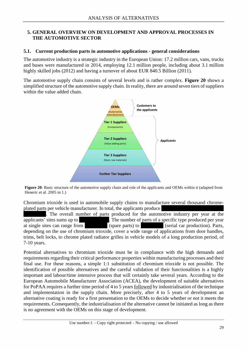
ANALYSIS OF ALTERNATIVES
Use number:1 – Copy right protected – No copying / use allowed
29
5. GENERAL OVERVIEW ON DEVELOPMENT AND APPROVAL PROCESSES IN THE AUTOMOTIVE SECTOR
5.1. Current production parts in automotive applications - general considerations The automotive industry is a strategic industry in the European Union: 17.2 million cars, vans, trucks and buses were manufactured in 2014, employing 12.1 million people, including about 3.1 million highly skilled jobs (2012) and having a turnover of about EUR 840.5 Billion (2011).
The automotive supply chain consists of several levels and is rather complex. Figure 20 shows a simplified structure of the automotive supply chain. In reality, there are around seven tiers of suppliers within the value added chain.
Figure 20: Basic structure of the automotive supply chain and role of the applicants and OEMs within it (adapted from Heneric et al. 2005 in 1.)
Chromium trioxide is used in automobile supply chains to manufacture several thousand chrome-plated parts per vehicle manufacturer. In total, the applicants produce xxxxxxxxxxxxxxxxxxxxxxxxx xxxxxxxxx. The overall number of parts produced for the automotive industry per year at the applicants’ sites sums up to xxxxxxxxxxxx. The number of parts of a specific type produced per year at single sites can range from xxxxxxxxx (spare parts) to xxxxxxxxx (serial car production). Parts, depending on the use of chromium trioxide, cover a wide range of applications from door handles, trims, belt locks, to chrome plated radiator grilles in vehicle models of a long production period, of 7-10 years.
Potential alternatives to chromium trioxide must be in compliance with the high demands and requirements regarding their critical performance properties within manufacturing processes and their final use. For these reasons, a simple 1:1 substitution of chromium trioxide is not possible. The identification of possible alternatives and the careful validation of their functionalities is a highly important and labour/time intensive process that will certainly take several years. According to the European Automobile Manufacturer Association (ACEA), the development of suitable alternatives for PoPAA requires a further time period of 4 to 5 years followed by industrialisation of the technique and implementation in the supply chain. More precisely, after 4 to 5 years of development an alternative coating is ready for a first presentation to the OEMs to decide whether or not it meets the requirements. Consequently, the industrialisation of the alternative cannot be initiated as long as there is no agreement with the OEMs on this stage of development.
OEMs(Automotive
manufacturers)
Tier 1 Suppliers(Components)
Tier 2 Suppliers(Value adding parts)
Tier 3 Suppliers(Steel, raw materials)
Further Tier Suppliers
Applicants
Customers to the applicants

ANALYSIS OF ALTERNATIVES
Use number:1 – Copy right protected – No copying / use allowed
30
A further point to consider in this context is the high complexity of supply chains in the automotive industry (Figure 21). The assembly of vehicles is performed in a complex network of manufacturing plants, which form a multi-tier system producing different parts, such as exterior sheets or engines. With an average number of 1500-4500 OEM suppliers, which have an average of 500-1500 suppliers themselves, tracking down chromium trioxide dependent parts is a time-consuming and complicated task.
Figure 21: Illustration of supply chain complexity
5.2. Current production parts - requirements for alternatives to metallic chrome coatings Metallic chrome plated parts are unique amongst others in terms of corrosion resistance, hardness, layer thickness, adhesive strength, coefficient of friction and abrasion resistance. Potential alternatives must be able to fulfil this crucial combination of requirements. To achieve this demanding goal, careful and time-consuming testing and evaluation of an alternative’s functional performance is needed. Current testing procedures include: laboratory tests, summer and winter tests and continuous-operation tests. Thorough evaluation of possible alternatives is mandatory to avoid failures in the field / upon daily use. Besides the safety aspects, the consequences could include expensive and highly brand damaging product recalls.
In a single vehicle, there are between 4000 to 9000 different main components and assemblies. Regarding the interior and exterior of a car, more than 150 different chrome plated parts can be mounted in a car. The range of different components is illustrated in Figure 22.

ANALYSIS OF ALTERNATIVES
Use number:1 – Copy right protected – No copying / use allowed
31
Figure 22: Car dismantled into constituent parts (Volkswagen AG, 2013) (left). Principal engine parts of a car (HubPages, undated) (right).
The requirements for surface performance are defined by the OEMs, not by the platers themselves. Over long years of development the OEMs have created very specific and unique requirements for exterior, as well as interior, vehicle parts including very precise expectation on the layer systems with which the parts are coated. For instance, the OEMs have extended the guarantees for product surfaces in favour of the end customer. Therefore, in the course of the last years the requirements on the surface performance have been drastically increased by the OEMs. It is the platers’ task to come up with solutions to comply with these expectations.
In case one substance has to be phased out or replaced, all affected components must be revalidated using suitable alternative materials. Even though the automobile industry is highly experienced in material testing procedures, the validation and testing of alternatives require a considerably long period of time due to the sheer number of parts involved. Even for simple changes it usually takes considerable time (even years) until a new or revised feature is thoroughly validated and the changes are implemented on a production level. Even adjusting the drawings of the specific car model accordingly can take up to two years, which is why adjustments are often not achieved within the lifetime of a car model. In particular, this is the case as potential alternatives would need to be tested in terms of their extension to large scale production and be ready for use by the sunset date in September 2017.
5.2.1. Consideration on Implementation of Alternatives In Chapter 7, the most promising alternatives are described and assessed with regard to their technical and economic feasibility. At the current stage of development, none of the tested alternatives can be seen as a general replacement for plating on plastic for exterior or interior automotive applications.
The following paragraphs demonstrate that even in case one of these alternatives could be considered technically and economically feasible according to suppliers the following tasks would have to be carried out first before it can be used by an OEM for serial production of a vehicle. The following steps are carried out within the life cycle of a car until End of Production (EOP) (see also illustration in Figure 23):
- Car Design: Development of concepts including modelling required functions, colours - Placing of Orders: Invitation of tender, negotiations, decision on main suppliers and sub-
suppliers, contracting - Validation of designs: Technologies must be mature, determination of inspection plan for
each part

ANALYSIS OF ALTERNATIVES
Use number:1 – Copy right protected – No copying / use allowed
32
- Prototype validation of parts and vehicle, logistics, readiness for serial production - Start of Production (SOP) - Face lift: From previous experience change of parts is possible, but only to a very restricted
extend - EOP after 7 years - Spare parts warranty for additional 10+ years
Figure 23: Typical life-time of a car model (According to VDA in FGK Chrom 2020, 2015).
Before materials and parts are considered for the development of a new car design, testing and approval by suppliers is necessary. Parallel to clearance by the OEM, new manufacturing processes would have to be adopted and established at the plating shops. It has to be confirmed that for the new process production capacities are sufficient. Only if technology and capacity approvals are granted, can a new material, coating or technology be considered for the concept development of a new car design. This process can easily last for 2 years.
During the research and development activities carried out by the applicants, two potential alternatives, Cr(III) electroplating and PVD, have been identified as promising Cr(VI)-free methods to replace PoPAA. Technical implementation of a Cr(III) based process in an existing plating shop would take at least 2.5 years. The timeline in Table 8 represents an exemplary situation for one applicant which is not entirely transferable to all applicants but can be used as a basis for estimations. Additionally, the scenario refers to the exchange of the Cr(VI) electroplating step. The exchange of the Cr(VI) etching pre-treatment, which is necessary to entirely eliminate Cr(VI) from the process, is not considered here. Moreover, it is important to note that these estimations refer to the technical implementation only and are hypothetical in a way that at the current state neither of the two techniques is considered able to replace the PoPAA-process as described in Chapter 7.
Table 8: Time-frame for implementation of a Cr(III) plating line.
Process step Time-Frame
Detailed project planning: chemical, process plant, constructional. In combination with experts and process supplier 6 months
Approval according to the relevant regulations (e.g.IPPC): Preparation of materials and application for approval, inclusive approval times 12 months
Acquisition of new baths and other materials as ion exchanger, transport waggons, etc. 6 - 8 months
Demolition of the old baths, disposal of electrolytes and associated steps 2 - 4 weeks
The process would be accompanied by major constructional changes for some companies, as for example demolition of parts of the building, rebuilding of an under-floor and re-creation of the cabling.
4 weeks
Finishing of construction steps and creation of new baths. 2 weeks

ANALYSIS OF ALTERNATIVES
Use number:1 – Copy right protected – No copying / use allowed
33
Process step Time-Frame
Initial production until the process is stable and reliable 6 months
For the introduction of a PVD-based processes, the second potential alternative assessed within this AoA, in principle the same procedure has to be followed. This includes the clearance by all OEMs, which is necessary to start the internal acquisition process. However, for the substitution of the electroplating facility by PVD more time is required. Due to space limitations the electroplating equipment would need to be completely removed before the new equipment could be installed.
5.2.2. Supply chain consideration The scenario presented above outlines the general tasks and timelines needed for the implementation of alternative technologies at the supplier level with subsequent approval and implementation by an OEM. This scenario does not consider the necessary tasks to be accomplished in case chromium trioxide has to be replaced concomitantly across the entire EU market. In that case, the following aspects need to be considered:
- None of the potential alternative technologies, as of today, has the production capacity to replace the market for PoPAA-parts.
- The supply chains, as well as the production capacities for several hundreds of millions of parts, for the whole automotive sector would need to be built from the ground up. In this context Figure 21 illustrates and underlines the complexity of the automotive supply chain from a market-wide perspective.
- Sufficient production capacity with the new technology would need to be identified, qualified and prove reliability;
- Field tests and acceptance tests at customers need to be performed. These "real life" tests extend the duration of qualification. This means more personnel is required at OEM level in order to carry out tests for a multitude of new parts and surfaces needing to be qualified at the same time.
- The interaction of the parts produced with the new technology need to be assured at the OEM level. The whole system of parts has to be evaluated, tested and qualified again. Likely, related parts will have to be redesigned to match the modification for a proper interplay. This enormous effort may be required for each vehicle series of an OEM. Within a single vehicle up to 150 parts may be affected. Again further supply chains, processes and suppliers are involved here (unpredictable time effects).
- The implications for the technology user or parts manufacturer who carry out surface treatment in house are substantial. In the first place they will likely need to secure the investment for a new facility or extensive reconstruction measures of the current electroplating facility. Once financial investment is secured, land has to be secured and all necessary permits need to be granted. The plant needs to be built and personnel skilled in the new technology are required. New customer relationships need to be built-up. Completely new technical qualifications need to be run through with lessons learned for the parts producer, as well as the OEM.
- It is critical to note that, in any case, the new technology cannot be used for repairs and for spare parts for the vast majority of parts already on the market, as specifications for a new technology development differ so much that they cannot be used on existing products. The same applies to products under current chromium trioxide-based development. For these products, the development cannot be switched to the alternative without losses in investment and required time for commercialisation, crucial factors for a company's success.

ANALYSIS OF ALTERNATIVES
Use number:1 – Copy right protected – No copying / use allowed
34
Consequently, the automotive industry considers a stepwise introduction of alternative technologies in new type-approved models (Directives 2005/64/EC and 2009/1/EC) (in a way that a future Cr(VI)-free Cr(III)-process could be used parallel to PoPAA) to be the preferred approach, but this is still discussed. An implementation will therefore not be feasible by the sunset date.
In addition, to ensure production volumes of vehicles are not affected, sufficient capacity for the production of alternative coatings in Europe must be built up. Otherwise imports from non-EU suppliers will bridge the supply gap. With EU-based OEMs sourcing from 70-80 % EU suppliers (20-50 % EU in case of non-EU) a change to non-EU suppliers would have a huge impact on the EU economy. With more than 16 million cars being built every year, building up sufficient capacity in Europe to cover all relevant parts is not possible by the sunset date. Moreover the direct supply chain will also be affected. The plating job is often done by Tier 3 suppliers; however, it is likely that the process of Tier 4 (injection moulding) as well as the process of Tier 2 (assembly line for e.g. air discharger, radio panels) will also move to non-EU suppliers. In these processes a lot of low-skilled jobs are involved.
The aforementioned multi-tier system, as well as the long-lasting nature of vehicles (up to 22 years and more) makes planning reliability crucial. Average life cycles of vehicles are about 22 years and include 3-5 years development time, 7 years of production and at least a 10 year service life, during which there is a need to guarantee availability of spare parts. The opportunity to introduce changes is only possible within a certain period of time, which decreases rapidly after type-approval. Therefore, the introduction of a potential alternative is accompanied by a long lead-time which cannot be met within the timeframe before the sunset date (refer to Figure 23).
The period to introduce changes decreases rapidly after type-approval by a certified body (Directives 2005/64/EC and 2009/1/EC). As shown in Figure 28, the period until sunset date (September 2017) could coincide with early stages of the automotive life-cycle, as well as with any stage of the minimum 22 year life-time of a car model. However, introducing changes is hardly feasible after a design is chosen.
5.3. Past model service parts - - requirements for alternative metallic chrome coating The EU passenger car fleet (Figure 24) consists of about 224 million vehicles. Approximately 36 % of these are older than 10 years (approx. 80 million cars).
Figure 24: EU passenger car fleet (share in % by age in 2010). Note: Information from 12 EU member states where information was available.
The majority of European cars are removed from the fleet after 13-15 years. This underlines the importance of an efficient supply of past model service parts beyond the end of serial production. Besides service consideration, national warranty obligations must be fulfilled. Therefore, a minimum

ANALYSIS OF ALTERNATIVES
Use number:1 – Copy right protected – No copying / use allowed
35
of 10 years availability of spare parts must be guaranteed (e.g. Germany: Civil law code §242). Commonly, past model service parts are even provided for vehicles that have been out of production for more than 20 years.
As mentioned above, the interrelation of components in vehicles is highly complex and the subject of thorough testing within the development phase of vehicles. Therefore, a 1:1 substitution of metallic chrome coatings applied by electroplating with chromium trioxide is not possible. Substance substitution may cause change of functional geometry, thermal durability and lead to unexpected impacts on related parts. To ensure that possible alternatives are interchangeable with original spare parts, a completely new type-approval is necessary. This may lead to major disadvantages, which are discussed in the following sections.
Complete testing of all related components may be necessary to exclude unexpected impacts and to ensure functionality and safety in the field. Additionally, validation processes must be based on the original vehicle, which may not be available in many cases.
Another point to be mentioned is the relatively small number of spare parts being produced. Compared to the high financial input needed for validation of alternatives, an enormous increase of price per item would be the consequence. The possibility of producing and stockpiling a sufficient amount of spare parts before sunset date should be discussed. However, this alternative may have some obvious drawbacks such as negative impacts on functionality due to chemical aging, waste of resources if spare parts are not needed for past model services, as well as high demand of stockpiling capacities.
In conclusion, the aforementioned arguments clearly show the need of metallic chrome coating from chromium trioxide electroplating in past model service part production.
5.4. Conclusive remarks on credible replacement scenario in the automotive sector The following aspects are relevant for OEMs regarding the change to alternative coating technologies in the automotive sector:
- Long-term quality and customer expectations have to be ensured by every alternative over the life-time of the product.
- A review period of 12 years is necessary because the high time and cost pressure in the automotive sector does not allow any business interruption planning security is needed
- Cr(III) systems, the alternative favoured by the applicants, have to be further elaborated and improved in order to be able to produce Cr(III)-coatings with a uniformed reproducible colour which is as close to Cr(VI) as possible.
- Further time is needed for elaboration and development, several development loops are expected, especially, to develop a Cr(VI)-free alternative for the etching pre-treatment.
Figure 25 outlines the need for a review period of not less than 12 years for the development, implementation of a Cr(VI)-free Cr(III) electroplating process (including etching pre-treatment and main treatment) and stepwise elimination of the Cr(VI)-based process. As a best estimate, 4 more years are required before the alternative is at an appropriate state. Before SOP for the first series equipped with Cr(VI)-free PoPAA-parts, the technology must be implemented at the coating facilities – in time to win the favor of the OEMs. Until the actual SOP, at least seven years are required (best estimate). From the SOP for the very first series until full elimination of Cr(VI), several challenges and uncertainties need to be solved, which is why it is not yet clear how long this process will take, given the fact that Cr(III) electroplating is still under development and a Cr(VI)-free etching pre-treatment is not available yet. In order to avoid gaps in production capacity that could force the OEMs

ANALYSIS OF ALTERNATIVES
Use number:1 – Copy right protected – No copying / use allowed
36
to search for producers outside the EU an elaborate strategy is required. The production capacities at the platers can only be built up successively. In the same way, the introduction at the OEMs cannot be conducted for all series at once. Therefore, at the beginning the Cr(III) process most likely needs to be run parallel to the Cr(VI) process. In this context, it needs to be clarified whether the platers are allowed to deliver both Cr(III) and Cr(VI) coated parts, likewise for compounds of the same kind with respect to the total number required until EOP. A strategy on the actual execution of the transition is not yet decided on. All in all it is not yet clear how much time is required until Cr(VI) is completely eliminated. In any case it will take at least until even in the car models in series all Cr(VI)-parts are replaced.

ANALYSIS OF ALTERNATIVES
Use number:1 – Copy right protected – No copying / use allowed
37
Figure 25. Minimum time required for an implementation of trivalent chromium electroplating and complete elimination of Cr(VI), including time required until readiness of Cr(III) as a completely Cr(VI)-free process. Time required for further R&D is a best estimate (especially regarding the etching pre-treatment). It is not yet clear, at what pace Cr(VI) can be completely replaced by Cr(III).
Years 0 3 5
Sunset Date
Development and Approval at OEM
Determination of Substrates and coatings
2016 20171 2 4 6
Technical modification of production sites for Cr(III) electroplating
7 8 9 10
Share of parts still treated with Cr(VI)
Share of parts treatedwith Cr(III)
SOP of first series
Substitution completed
?
Uncertainties: - Production capacities Cr(III)?- Mixed use of Cr(VI) and Cr(III) parts?
necessary/possible at OEMs?- Long-term performance Cr(III)?- Running series: Changes during face lift?
R&D for further development of the Cr(III)-process including Cr(VI)-free etching pre-treatment
100 %
0 %
> 2 years2026
x

ANALYSIS OF ALTERNATIVES
Use number:1 – Copy right protected – No copying / use allowed
38
6. ANNUAL TONNAGE
The annual tonnage band for the use of chromium trioxide in plating on plastics for the automotive industry is about 560 tonnes per year.

ANALYSIS OF ALTERNATIVES
Use number:1 – Copy right protected – No copying / use allowed
39
7. IDENTIFICATION OF POSSIBLE ALTERNATIVES
7.1. Description of efforts made to identify possible alternatives
To prepare an AfA for chromium trioxide, the industry consortium CTAC (Chromium Trioxide Authorisation Consortium) of 150+ members was launched in 2012. The aim of CTAC was to efficiently gather and analyse all necessary information for the three pillars of the authorisation dossier (CSR, AoA, SEA). Members of FGK have either been members of CTAC or hold a letter of access to the CTAC AfA. Therefore, next to information and experience from the FGK members, also content from CTAC is used as a basis for this AoA.
7.1.1. Research and development Much effort on alternatives for the etching with chromium trioxide as well as for the electroplating with chromium trioxide has been made and is still ongoing by the members of FGK. R&D is generally performed by specific companies by testing different plated products in feasibility studies. The unique functionalities of Cr(VI) as component in chromium trioxide, (explained in detail in Section 3.3) make it an ideal and not easy to replace substance where superior requirements with regard for example to aesthetics/colour, corrosion and chemical resistance or abrasion resistance demanding conditions have to be fulfilled, especially where controlled etching is required. It is very difficult to find a single alternative which replaces all the multi-functionality of Cr(VI) simultaneously.
FGK & ZVO
The 12 applying German companies in terms of the present AfA (platers of plastic for the automotive industry) are organised in the FGK (Fachverband Galvanisierte Kunststoffe, www.f-g-k.org/index.php) and in the ZVO (Zentralverband Oberflächentechnik, http://www.zvo.org/). Both are involved in large R&D efforts. These companies are focussed on the technical feasibility and improvement of metallic chrome coatings from Cr(III) electrolytes, as they are considered the most promising alternative to PoPAA.
Significant efforts on Cr(III) have been made and company specific feasibility studies of different plated products are performed. Two comparative studies with extensive laboratory and field tests of different metallic chrome coating from Cr(III) electrolytes (with and without a Cr(VI) based post-treatment passivation) derived from different electrolytes - tested versus chrome coatings from chromium trioxide - have been performed. In 2012, the study has been performed with more than 530 coated plastic patterns (thereof 230 in field tests and about 300 in lab tests).
A second comparative study was performed between 2013 and 2014. In this second study, 12 different chrome coatings, of which eight were sulphate based and four chloride based Cr(III) electrolytes, have been tested from seven different suppliers of the electrolytes. One major difference to the first study was that no Cr(VI)-containing passivation post-treatments were accepted. Most of the suppliers provided new and optimised chemicals. The main focus of the test was the colour (aesthetic appearance) of the coatings, its corrosion resistance (tested in CASS and NSS tests according to EN ISO 9227), and the overall coating performance with respect to layer thickness, nickel leaching and climate / temperature change resistance. In this second trial, a total of 3000 plastic patterns provided with different types of metallic chrome coatings from Cr(III) and Cr(VI) electrolytes (chromium trioxide) were compared. Thereof 2400 patterns were examined in laboratory and the remaining 600 were mounted on a total of 72 cars and 10 trucks. The test patterns were applied to the front, the back and in the lateral area of the vehicles. The cars and trucks were used throughout the winter period and examined in spring. As a result of the field test, and presumably due to the rather mild winter

ANALYSIS OF ALTERNATIVES
Use number:1 – Copy right protected – No copying / use allowed
40
2013/2014, only few major failures of the patterns were determined. On average, the coated patterns from Cr(III) electroplating performed slightly worse than the coated patterns from chromium trioxide electroplating. It is striking that the amount of smut on all Cr(III) coated patterns after the field tests was higher than the patterns coated with chromium trioxide electroplating.
A third study was carried out between 2014 and 2015. Based on the results from the previous years, only nine optimised sulphate-based Cr(III) electrolytes were tested. Again, no Cr(VI) containing passivation post-treatments were accepted. Furthermore, requirements regarding brightness of the coating were made. In the laboratory, around 2000 patterns were tested, 550 patterns were subject to extensive field testing. The results are described and evaluated in Chapter 7.
In November 2015, the next trials started with 8 sulphate-based Cr(III) electrolytes on 78 passenger cars and 10 trucks. First results are expected by mid-2016.
Fraunhofer IST The Fraunhofer IST research institute has applied for an R&D project on the future use of electroplated plastic parts, to be funded by the AiF (Arbeitsgemeinschaft industrieller Forschungs-vereinigungen) and BMBF (Federal Ministry of Education and Research). The project is scheduled with a three year timeframe. The decision on the approval of this R&D project is currently anticipated.
Indeed, on the basis of the aforementioned unique combination of properties and diverse functionalities, where alternatives have to be identified and implemented in all processes (etching of plastics and electroplating), the identification and implementation of completely chromium trioxide free alternatives, also with regard to the extensive and promising research and innovative technologies already made, no one-to-one solutions are currently expected and the implementation of a completely chromium trioxide free process is not expected before at least 12 years after sunset date.
7.1.2. Consultations As part of the extensive R&D-efforts performed, there is active exchange among the members of applicants in course of their commitment in the FGK in order to stay up to date and push forward the development of alternatives for PoPAA. For the purpose of the present AfA the extensive data collection from CTAC has been re-evaluated by the applying parties in several cross-company work group meetings and discussed with members of ACEA and ZVO. All alternatives have been re-assessed for the application of PoPAA
In summary, the categorised table of alternatives listed below is the outcome of extensive literature and practical research, and consultations with technical experts in the field of surface treatment.
7.2. List of possible alternatives
There are two potential alternatives which are currently in focus of research and development activities in context with a Cr(VI)-free alternative to PoPAA: Trivalent chromium plating and PVD-based processes. These two processes differ fundamentally. Basically, trivalent chromium plating, is a galvanic process just like Cr(VI) electroplating in PoPAA, but in order to achieve a galvanisable surface, an alternative to the Cr(VI) etching pre-treatment has to be developed as well. In contrast to that, the PVD-based processes require fundamentally different technology, but do not need an etching pre-treatment. Figure 26 briefly outlines the conceptual differences connected with the two alternative concepts.

ANALYSIS OF ALTERNATIVES
Use number:1 – Copy right protected – No copying / use allowed
41
Figure 26: Concepts behind the two category 1 main-treatment alternatives
Within the following sections, the two potential alternative concepts are discussed. For a better overview of the different processes, the assessment is made for the pre-treatment step (Table 9) and the electroplating step (Table 10) separately. Importantly, both steps are interlinked and cannot be seen as standalone processes, to be replaced independently from each other. Without an adequate pre-treatment, the high-quality of the final product cannot be reached. However, most important key functionalities are related to the chromium trioxide based electroplating step.
According to their relevance, the potential electroplating alternatives are classified as Category 1 (focused in the dossier, relevant R&D on these substances ongoing) or Category 2 (clear technical limitations, may only be suitable for niche applications but not as general alternative).
Table 9: List of alternatives to Cr(VI) etching pre-treatment categorised.
Category Alternative Part of Process Chain
Category 1 alternative Potassium permanganate-based etching solution Etching of plastics
Category 2 alternatives
Mineral acid-based etching solutions Etching of plastics
Ionic liquids Etching of plastics
Polyamide Alternative substrate / etching of plastics
Table 10: List of alternatives to Cr(VI) electroplating categorised.
Category Alternative
Category 1 alternatives Trivalent chromium plating (+ a Cr(VI)-free etching pre-treatment)
PVD-based processes
Category 2 alternatives Wet lacquering
Electroless Nickel plating
Cr(III)-plating (see chapter 8.2.1) PVD-based processes (see chapter 8.2.2.)
Galvanic process similar to PoPAA
Etching pre-treatment required to date not Cr(VI)-free potential alternative e.g. potassium permanganate-based etching solution (assessed in chapter 8.1.1.)
Potential alternative favoured by the applicants
Coating technology fundamentally different from PoPAA
No etching pre-treatment required Different process for surface preparation (lacquering)
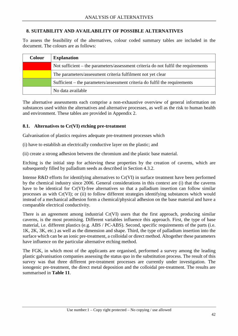
ANALYSIS OF ALTERNATIVES
Use number:1 – Copy right protected – No copying / use allowed
42
8. SUITABILITY AND AVAILABILITY OF POSSIBLE ALTERNATIVES
To assess the feasibility of the alternatives, colour coded summary tables are included in the document. The colours are as follows:
The alternative assessments each comprise a non-exhaustive overview of general information on substances used within the alternatives and alternative processes, as well as the risk to human health and environment. These tables are provided in Appendix 2.
8.1. Alternatives to Cr(VI) etching pre-treatment
Galvanisation of plastics requires adequate pre-treatment processes which
(i) have to establish an electrically conductive layer on the plastic; and
(ii) create a strong adhesion between the chromium and the plastic base material.
Etching is the initial step for achieving these properties by the creation of caverns, which are subsequently filled by palladium seeds as described in Section 4.3.2.
Intense R&D efforts for identifying alternatives to Cr(VI) in surface treatment have been performed by the chemical industry since 2006. General considerations in this context are (i) that the caverns have to be identical for Cr(VI)-free alternatives so that a palladium insertion can follow similar processes as with Cr(VI); or (ii) to follow different strategies identifying substances which would instead of a mechanical adhesion form a chemical/physical adhesion on the base material and have a comparable electrical conductivity.
There is an agreement among industrial Cr(VI) users that the first approach, producing similar caverns, is the most promising. Different variables influence this approach. First, the type of base material, i.e. different plastics (e.g. ABS / PC-ABS). Second, specific requirements of the parts (i.e. 1K, 2K, 3K, etc.) as well as the dimension and shape. Third, the type of palladium insertion into the surface which can be an ionic pre-treatment, a colloidal or direct method. Altogether these parameters have influence on the particular alternative etching method.
The FGK, in which most of the applicants are organised, performed a survey among the leading plastic galvanisation companies assessing the status quo in the substitution process. The result of this survey was that three different pre-treatment processes are currently under investigation. The ionogenic pre-treatment, the direct metal deposition and the colloidal pre-treatment. The results are summarised in Table 11.
Colour Explanation
Not sufficient – the parameters/assessment criteria do not fulfil the requirements
The parameters/assessment criteria fulfilment not yet clear
Sufficient – the parameters/assessment criteria do fulfil the requirements
No data available

ANALYSIS OF ALTERNATIVES
Use number:1 – Copy right protected – No copying / use allowed
43
Table 11: Status of possible pre-treatment substitution processes.
Type Status
Ionogenic pre-treatment No activities known
Direct metal deposition Minor activities, maximal on the level of technical centres
Colloidal pre-treatment
Most activities performed:
1. ABS: some sanitary uses in maturity phase
2. ABS/PC T45: tests performed on maturity phase
3. 2K ABS: level of technical centres
4. 2K ABS/PC T45: level of technical centres
As already described, palladium deposited within the caverns acts as a catalyst for the subsequent electrochemical reaction and the more caverns a part has the more palladium can be deposited. It has to be mentioned that Cr(VI) is able to inhibit the process of palladium deposition which is important to prevent undesired galvanisation of the racks that hold the parts. This is of special importance for Cr(III) electroplating, which is the alternative to PoPAA favoured by the applicants and their customers. Despite significant efforts achieved over the last years, the overall maturity of the alternative to eliminate Cr(VI) from the plating process depends on the availability of a Cr(VI)-free etching pre-treatment.
Summarised, the Cr(VI)-free pre-treatment steps have different development levels for the different plastic materials. The first promising results have been found for ABS, but for multi-component systems major difficulties have to be overcome. The time-frame until the process is at the technical maturity phase is at least several years.
In the following sections the status and technical readiness levels for the most promising Cr(VI)-free etching alternatives are discussed in detail.
8.1.1. Pre-Treatment: Category 1 alternative: Potassium permanganate based etching solution
8.1.1.1 Substance ID and properties / process description Potassium permanganate (KMnO4) is a strong oxidising agent with manganese in the oxidation state of VII. It is widely used for water disinfection. Acidic permanganate solutions are reduced to Mn2+ (MnO) giving the solution a pink colour. Under neutral conditions, permanganate is reduced to Mn4+ (MnO2), exhibiting a brownish colour to all materials that are in contact with the solution. In alkaline solutions, potassium permanganate is spontaneously reduced to Mn6+ (K2MnO4), having a green colour.
A non-exhaustive overview of general information on substances used within this alternative and the risk to human health and the environment is provided in Appendix 2.1.1.

ANALYSIS OF ALTERNATIVES
Use number:1 – Copy right protected – No copying / use allowed
44
8.1.1.2 Technical feasibility As stated during the consultation, extensive R&D on this alternative has been performed and is still ongoing. First tests were made with a small series of experiments showing very different results.
Potassium permanganate-based etching is performed either under acidic or under alkaline conditions. While the acidic permanganate etching is performed with a bath temperature of 69 °C and an etch time of 9 minutes, the alkaline permanganate etching is carried out with a bath temperature of 45 °C and an etch time of 5 minutes. In both cases, a number of subsequent steps such as rinsing, hot rinsing, neutralisation, etc. are required before plating on plastics can be performed.
In Figure 27, plastic surfaces etched with different kinds of etching solutions are shown.
Figure 27: Comparison of typical etched plastic surfaces (left: after chromium trioxide etching, middle: after acidic permanganate etching, right: after alkaline permanganate etching). (Kunststoff Institut Lüdenscheid, 2014).
According to Ziegert (2013), acidic permanganate etching solutions show a rapid self-reactivity and decomposition. This results in a relatively short lifetime of such etching solutions. Alkaline manganese etching solutions have a reasonable stability and are environmentally friendly. However, the etching capability, especially on plastic substrates (like ABS, PC, Polyetherimide (PEI), or blends), is not very strong so relatively long treatment periods are needed.
At the current stage of development, the major issue with permanganate based etching solutions in general is that the adhesive properties required for the subsequent coating steps are not sufficiently provided. As shown in Figure 27, the etching rate is much weaker than using a chromium trioxide based etching solution. In general, only a small series of experiments with very different results have been performed. Etching key functionalities, such as the depth, form and density of the cavities were generally found to be different, but in line with the requirements (no change of the substrate’s micro roughness), whereas the adhesive properties were found to be less than chromium trioxide based etching. The inferior adhesive properties lead to extensive blistering of the PoPAA surface. As a consequence, the high quality requirements regarding aesthetics of the final product cannot be met for the respective industry sectors.
The alternative is currently not suitable for selective etching of 2K and 3K parts.
Permanganate etching is a wet-in-wet process, the overall technique is comparable to the chromium trioxide based process. Therefore, the alternative process was stated to be compatible with the subsequent electroplating step as far as the plastic parts are concerned. However, for its strong oxidative properties, cross contaminations with potassium permanganate are highly critical for the subsequent coating baths. The next step, the activation, is disturbed by the input of potassium permanganate. Furthermore, Cr(III), which is at the moment the most favourable alternative to Cr(VI)-electroplating, is highly sensitive to impurities. Cr(III) is oxidised to Cr(VI) by potassium permanganate, the Cr(VI) would spoil the whole bath.
Given the chemical nature of permanganate solutions, the bath maintenance is much more complex. During the etching process, Mn7+ is reduced and MnO2 is precipitated from the etching solution,

ANALYSIS OF ALTERNATIVES
Use number:1 – Copy right protected – No copying / use allowed
45
causing interferences with the etched substrate. Finally, increased costs for the disposal of high amounts of MnO2 sludge, created during the process have to be taken into account. The MnO2 deposits at the base of the etching baths highly influence the overall etching performance. Also, as the etching performance is not adequate, the quality of the final product will decrease over time. Chemical instability and disadvantages in the production and handling, as well as waste water treatment, are the main issues of this system.
All of these technical limitations lead to the conclusion that permanganate based etching alternatives are currently not feasible for high volume production. It is also very important to mention that MnO2 is an oxidising agent and chloride can be oxidised to elemental chlorine. Therefore, manganese dioxide has to be kept separate from chlorides during the processes of surface coating and neutralisation and the storage of sludge.
Adequate surface preparation
Selective etching of 2K, 3K compounds Adhesion Compatibility with
substrates
8.1.1.3 Economic feasibility
Against the background of the significant technical failure of this alternative, no detailed analysis of economic feasibility was conducted. Indications were made that showed the permanganate based etching to be more expensive compared to chromium trioxide based etching solutions, given the large maintenance efforts and large amounts of sludge resulting in high disposal costs.
In order to further improve technically feasibility and for further development or adaptation of an adequate pre-treatment, investment in R&D activities are necessary in the coming years.
The PoPAA process is complex and involves numerous steps. Chromium trioxide is critical in the etching pre-treatment and the main chrome electroplating process. Over the last years, the applicants have focused on trivalent chromium plating as the most desirable alternative to PoPAA main treatment for the automotive industry. Although the performance of metallic chrome coatings from Cr(III) electrolytes have improved, the maturity of an alternative Cr(VI)-free pre-treatment remains very low. However, the pre-treatment cannot be separated or individually modified without impairing the overall process and the properties of the final product. Compatibility and technical performance of the overall system are therefore considerations of primary importance for material specification.
Re-qualification of automotive parts is a very costly and time consuming procedure (see chapter 5.2 and SEA). Stepwise introduction of the main-treatment and subsequently of the pre-treatment is accompanied by full re-qualification of the coating at the OEMs and would increase these efforts significantly.
Consequently, it is advisable to further develop the entire Cr(III) electroplating process until it is completely Cr(VI)-free before industrial implementation and OEM qualification.
8.1.1.4 Reduction of overall risk due to transition to the alternative As the alternative is not technically feasible, only classification and labelling information of substances and products reported during the consultation were reviewed for comparison of the hazard profile. Based on the available information on the substances used within this alternative (see Appendix 2.1.1), potassium permanganate would be the worst case with a classification as Oxid Solid

ANALYSIS OF ALTERNATIVES
Use number:1 – Copy right protected – No copying / use allowed
46
2, Acute Tox. 4, Aquatic Acute 1 and Aquatic Chronic 1. As such, transition from chromium trioxide - which is a non-threshold carcinogen - to one of these substances would constitute a shift to less hazardous substances.
8.1.1.5 Availability The substance potassium permanganate is commercially available and widely used for a number of different applications. With regard to its use as an alternative for etching of plastics, different companies are working on the technical issues. As stated during the consultation, further R&D is necessary to develop the alternative in a way to safely gain surfaces of high quality. R&D efforts were stated on the overall development of the alternative. Given the very early (laboratory) stage of R&D and the clear technical limitations at the current stage, it is not expected that permanganate etching will become technically feasible within the next years. In addition, industrial implementation and OEM qualification procedures for certain applications and sectors would be required afterwards.
8.1.1.6 Conclusion on suitability and availability for potassium permanganate based etching solution
At the current stage, permanganate based alternatives for etching of plastic substrates is not technically feasible and has economic disadvantages. From a technical point of view, the major drawback is the clearly insufficient adhesive properties, leading to delamination and an unacceptable aesthetic appearance of the final coating. Furthermore, the permanganate process leads to deposition of sludge, which causes high maintenance and costs. Further R&D is necessary to overcome the existing technical hurdles. It is expected the development until the alternative will be technically feasible and industrialised will take at least 10 years after the sunset date.
8.1.2. Pre-Treatment: Category 2 alternatives The assessment for those methods rated as category 2 alternatives for the etching pre-treatment is provided in the following Table.
Table 12: Assessment of category 2 alternatives for Cr(VI) etching pre-treatment.
Alternative Substance ID and properties Feasibility Mineral acid based etching solution
Different mineral acids are currently under evaluation as alternatives to chromium trioxide etching pre-treatment. Research is currently focused on using sulphuric acid composed with other acids, such as phosphoric acid and nitric acid, or with additives, such as peroxymonosulphate salts or peroxidisulphate salts.
- The alternative is not selective for ABS (butadiene 1.3 removal) only and may also affect the other components. In addition, the alternative does not prepare the substrate for an adequate adhesion of the subsequent coating.
- Generally, issues with bath maintenance (water treatment, increased bath temperature, sludge deposition) are not solved yet.
- A major concern was stated to be swelling of the plastic substrate. It was confirmed that it is not technically possible to prevent swelling of the plastic surface when using any kind of acidic replacement etching solutions, and therefore, no further R&D on this alternative will be performed.
In summary: With regard to etching of plastic substrates, mineral acid based solutions are

ANALYSIS OF ALTERNATIVES
Use number:1 – Copy right protected – No copying / use allowed
47
Alternative Substance ID and properties Feasibility clearly not technically suitable as an alternative to chromium trioxide based etching. The major limitation is the swelling of the plastic substrate and the non-selectiveness for ABS, when using any kind of mineral acid. It is unlikely that these solutions will become technically feasible at all.
Ionic liquids Ionic liquids of different kinds in various combinations are currently tested for their suitability for an etching pre-treatment of plastics prior to Cr(VI) electroplating. Development is currently on laboratory stage.
- Early R&D status (not higher than pilot-scale level in the laboratory)
- Large-scale implementation uncertain - Selectivity concerning parts and racks
questionable - No process technology available for
adequate process control - Waste water treatment required, but no
solution available. - Costly solution and process In summary: Ionic liquids are not ready to be implemented as an alternative for chromium trioxide etching pre-treatment. Given the uncertainties regarding process control and waste water treatment, it is questionable whether they will ever become a feasible alternative at all.
Alternative substrate: Polyamide (PA)
PA consists of macromolecules which contain repeating amides. Polyamides can be of natural (in wood and silk) or of synthetic origin produced by polymerisation. Three different kinds of polyamides are available, classified as Aliphatic polyamides, for example PA6 [NH-(CH2)5-CO]n and PA6.6 [NH-(CH2)6-NH-CO-(CH2)4-CO]n, commercially traded as Nylon, Semi aromatic polyphthalamides, for example PA 6T (hexamethylenediamine + terephthalic acid), commercially traded as Trogamid and, Aromatic polyamides, for example paraphenylenediamine + terephthalic acid, commercially traded as Kevlar. The melting temperature of polyamides is generally higher compared to that of ABS. The melting temperature of PA6 is at 220 °C and of PA6.6 at 260 °C. Using PA instead of ABS would eliminate the need for a chromium trioxide based etching pre-treatment, because due to the different chemical composition of PA, surfaces can be etched without chromium trioxide (for example using sulphonation).
The major drawback of PA is that the raw part must be of very high quality. In contrast to conventional plastic substrates, the etching pre-treatment removes even small defects and imperfections, but with PA as substrate, small edges, blisters or unevenness will occur on the final surface. In that case, the aesthetic properties of the final product are not in line with the demanding requirements of the automotive OEMs. In summary: Due to unsatisfying results regarding the surface appearance after galvanising (surface not smooth), especially with a Cr(VI)-free sweller process, polyamide is not regarded as a true alternative for ABS or PC in order to find solutions to eliminate chromium trioxide from the etching pre-treatment in PoPAA.
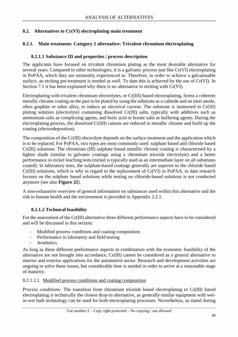
ANALYSIS OF ALTERNATIVES
Use number:1 – Copy right protected – No copying / use allowed
48
8.2. Alternatives to Cr(VI) electroplating main treatment
8.2.1. Main treatment: Category 1 alternative: Trivalent chromium electroplating
8.2.1.1 Substance ID and properties / process description The applicants have focused on trivalent chromium plating as the most desirable alternative for several years. Compared to other technologies, it is a galvanic process just like Cr(VI) electroplating in PoPAA, which they are eminently experienced in. Therefore, in order to achieve a galvanisable surface, an etching pre-treatment is needed as well. To date this is achieved by the use of Cr(VI). In Section 7.1 it has been explained why there is no alternative to etching with Cr(VI).
Electroplating with trivalent chromium electrolytes, or Cr(III)-based electroplating, forms a coherent metallic chrome coating on the part to be plated by using the substrate as a cathode and an inert anode, often graphite or other alloy, to induce an electrical current. The substrate is immersed in Cr(III) plating solution (electrolyte) containing dissolved Cr(III) salts, typically with additives such as ammonium salts as complexing agents, and boric acid or borate salts as buffering agents. During the electroplating process, the dissolved Cr(III) cations are reduced to metallic chrome and build up the coating (electrodeposition).
The composition of the Cr(III) electrolyte depends on the surface treatment and the application which is to be replaced. For PoPAA, two types are most commonly used: sulphate based and chloride based Cr(III) solutions. The chromium (III) sulphate based metallic chrome coating is characterised by a lighter shade (similar to galvanic coatings using a chromium trioxide electrolyte) and a better performance in nickel leaching tests (nickel is typically used as an intermediate layer on all substrates coated). In laboratory tests, the sulphate-based coatings generally are superior to the chloride based Cr(III) solutions, which is why in regard to the replacement of Cr(VI) in PoPAA, to date research focuses on the sulphate based solutions while testing on chloride-based solutions is not conducted anymore (see also Figure 32).
A non-exhaustive overview of general information on substances used within this alternative and the risk to human health and the environment is provided in Appendix 2.2.1.
8.2.1.2 Technical feasibility For the assessment of the Cr(III) alternative three different performance aspects have to be considered and will be discussed in this section:
- Modified process conditions and coating composition - Performance in laboratory and field testing - Aesthetics
As long as these different performance aspects in combination with the economic feasibility of the alternative are not brought into accordance, Cr(III) cannot be considered as a general alternative to interior and exterior applications for the automotive sector. Research and development activities are ongoing to solve these issues, but considerable time is needed in order to arrive at a reasonable stage of maturity.
8.2.1.2.1 Modified process conditions and coating composition
Process conditions: The transition from chromium trioxide based electroplating to Cr(III) based electroplating is technically the closest drop-in alternative, as generally similar equipment with wet-in-wet bath technology can be used for both electroplating processes. Nevertheless, as stated during

ANALYSIS OF ALTERNATIVES
Use number:1 – Copy right protected – No copying / use allowed
49
the internal consultation, the transition from chromium trioxide to Cr(III) cannot simply be performed by changing the plating electrolyte. Cr(III) baths are much more sensitive to metallic impurities and to the acidity of the bath than conventional chromium trioxide plating baths. Even small deviations in the process conditions can strongly influence the deposition success, the layer quality and the final appearance. Enormous adaptations of the process technology are needed to run a Cr(III) plating line under robust conditions:
- As Cr(III) plating baths are very sensitive to impurities, an ion exchanger (special resin) and a number of additional basins/baths are needed to enable adequate rinsing processes to reduce impurities as much as possible. This is necessary for both the pre-treatment bath technology as well as the Cr(III) plating step. Based on the experience of BIA, the process line has to be lengthened for nine meters. Clearly, modifications of serial production lines, especially for processing of large parts, is a very costly process. Several companies stated during the consultation that the building conditions simply do not allow for the installation of further baths. The companies carrying out these operations explained that new buildings would have to be constructed.
- Current density needed for an adequate dispersion of the metal layer is higher than for Cr(VI), significant amounts of hydrogen and oxygen are generated, exhaust ventilation has to be 100m³/h/Position. Cr(III) plating bath will warm up and must be cooled using additional systems technology.
- A special anode technique based on Nickel is needed for Cr(III) plating. Using inappropriate anodes will lead to degradation of the electrolyte.
- For adequate surface preparation, an additional Cr(VI)-free passivation step is needed after the Cr(III) plating step. The passivation solutions are concentrated and are carried over in subsequent process steps. Cathodes needed are made from graphite.
- Numerous additives are needed to work with an Cr(III) electrolyte. Most of these additives have to be dosed manually. Performance of these additives do not always react very specifically, bearing the risk of overdosing.
- Rack mounting is different and not easy to handle. - Analytical efforts are much higher for adequate control of the bath composition with all its
additives. Analysis of layer thickness and colour has to be performed on a daily basis. (Maintaining Cr(III) bath quality takes about 14 hours per week, compared to 2 hours per week for the Cr(VI)-bath).
Consequently, establishing a reliable process for metallic chrome layers from a Cr(III) electrolyte of reproducible quality (colour, corrosion resistance, thickness, hardness, etc.) is challenging as the Cr(III) based plating process requires careful handling.
Coating composition: Metallic chrome coatings derived from Cr(III) do not have the same composition and orientation as metallic chrome coatings derived from Cr(VI). While Cr(VI) generates a Chrome-oxygen compound with a nano-crystalline orientation, Cr(III) electrolytes will generate a Chrome-Carbon alloy with almost no orientation (Figure 28). The significant structural differences between a electrodeposited Cr(III) and a electrodeposited Cr(VI) coating lead to differences in performance described here (Liang et al., 2013). Essential secondary properties derived by the different composition of metallic chrome coatings from Cr(III) are not necessarily the same and have to be evaluated carefully.

ANALYSIS OF ALTERNATIVES
Use number:1 – Copy right protected – No copying / use allowed
50
Figure 28: Metallic chrome coatings derived from Cr(VI) electrolytes (left) Cr(III) electrolytes (right) (Enthone, 2015)
8.2.1.2.2 Performance in laboratory and field testing
The following technical assessment is based on the latest results from the extensive FGK laboratory and field studies 2014/2015 described in Section 6.1.1. According to the development and optimisation of Cr(III) electrolytes over the last years, testing is focused on sulphate-based Cr(III) electrolytes.
Corrosion resistance: The corrosion resistance of metallic chrome coatings from Cr(III) electrolytes is dependent on numerous parameters, such as the type of electrolyte used (sulphate Cr(III) based or chloride Cr(III) based), the underlying layer system (copper, nickel intermediate layer, etc.) and whether the coating is provided with a subsequent passivation.
Following the already performed R&D in recent years, an improvement of the corrosion resistance of Cr(III) based metallic chrome coatings can be determined. However, recent results showed that the corrosion resistance of metallic chrome coatings from Cr(III) electrolytes is inconsistent between the nine electrolytes tested and still lower compared to metallic chrome coatings from chromium trioxide electroplating. So far, these systems do not fulfil the automotive requirements (for example, exterior 480 h NSST, 96 h CASS EN ISO 9227) in the laboratory. Few of these systems performed close to chromium trioxide derived metallic chrome coating.
Stone-chip / climate change resistance: The results from recent testing showed that the performance of the Cr(III) electrolytes was not comparable to Cr(VI) (Table 13).
Table 13: Results from combined Stone-chip / climate change testing. (A) Subsequent NSS (B) subsequent CASS including respective pictures.
Variation Coating Evaluation1 Not OK (Rust formation)2 Not OK (Rust formation)3 Not quite OK (Some rust formation)4 Not OK (Rust formation)5 OK (Minimal rust formation)
6Not OK (Extreme formation of rust and stains )
7Not quite OK(Rust formation and blistering)
8Not quite OK (Rust formation and blistering)
9 Not OK (Heavy rust formation)mp Cr(VI) OK (Minimal rust formation)mc Cr(VI) x
Cr(III)
Cr(VI)
Variation Coating Evaluation1 Not quite OK (Some rust formation)2 Not quite OK (Rust and pore formation)3 OK (Stains)4 Not quite OK (Rust and pore formation)5 Not quite OK (Rust and pore formation)
6Not quite OK (Formation of rust and stains )
7 Not quite OK (Some rust formation)
8 OK (Minimal rust formation)9 Not OK (Heavy rust formation)
mp Cr(VI) OK (Minimal rust formation)mc Cr(VI) x
Cr(III)
Cr(VI)

ANALYSIS OF ALTERNATIVES
Use number:1 – Copy right protected – No copying / use allowed
51
Chemical resistance: Chemical resistance was tested according to drop test (OEM specification), all electrolytes fulfilled the requirements. When tested against other chemicals, results were inconsistent: exposure to sun crème lead to insufficient results but when tested against hand crème the results were sufficient. Based on the information provided in the consultation, the chemical resistance with regard to crème does not currently fulfil the requirements of the automotive sector.
Wear resistance / abrasion resistance: It was stated that the abrasion resistance of Cr(III) electrolytes is comparable to metallic chrome coatings produced from Cr(III) electrolytes. Only minimal or no wear or colour deviation was observed.
Nickel leaching: The tested Cr(III) electrolytes performed in line with the requirements.
Weathering: Weathering tests according to an OEM specification clearly demonstrated severe corrosion after 5 months. Further testing (e.g. carwash) is still ongoing.
Field testing: Between November 2014 to April 2015, 78 vehicles were equipped with FGK testing patterns. As this winter was more severe than the rather mild winter of 2013/2014, results were on average worse this year for Cr(III) as well as Cr(VI). Results differ partly between passenger cars and trucks. Only a few major failures of the patterns were determined. Interestingly, the amount of smut on all Cr(III) coated patterns after the field tests was higher than the patterns coated with chromium trioxide electroplating. All Cr(III) samples became significantly darker over the time.
8.2.1.2.3 Aesthetics
In general, the metallic chrome plated surface from trivalent chromium electroplating is of a similar appearance to surfaces created by chromium trioxide based electroplating. Nevertheless, the final colour is not silvery-bluish but slightly yellowish/brownish. The exact colour of the coating is a result of the electrolyte used: sulphate based coatings for example are slightly lighter, while chloride based coatings are slightly darker (Blittersdorf, 2013).
In Figure 29, several chrome coated parts are shown to highlight the range of colour shades which can occur with this alternative. The green labelled patterns are produced from trivalent chromium electrolytes of different suppliers whereas the orange labelled parts derived from traditional hexavalent chromium electrolytes. The yellowish/brownish colour of products is caused independent from the electrolyte used and has been observed on all tested samples.
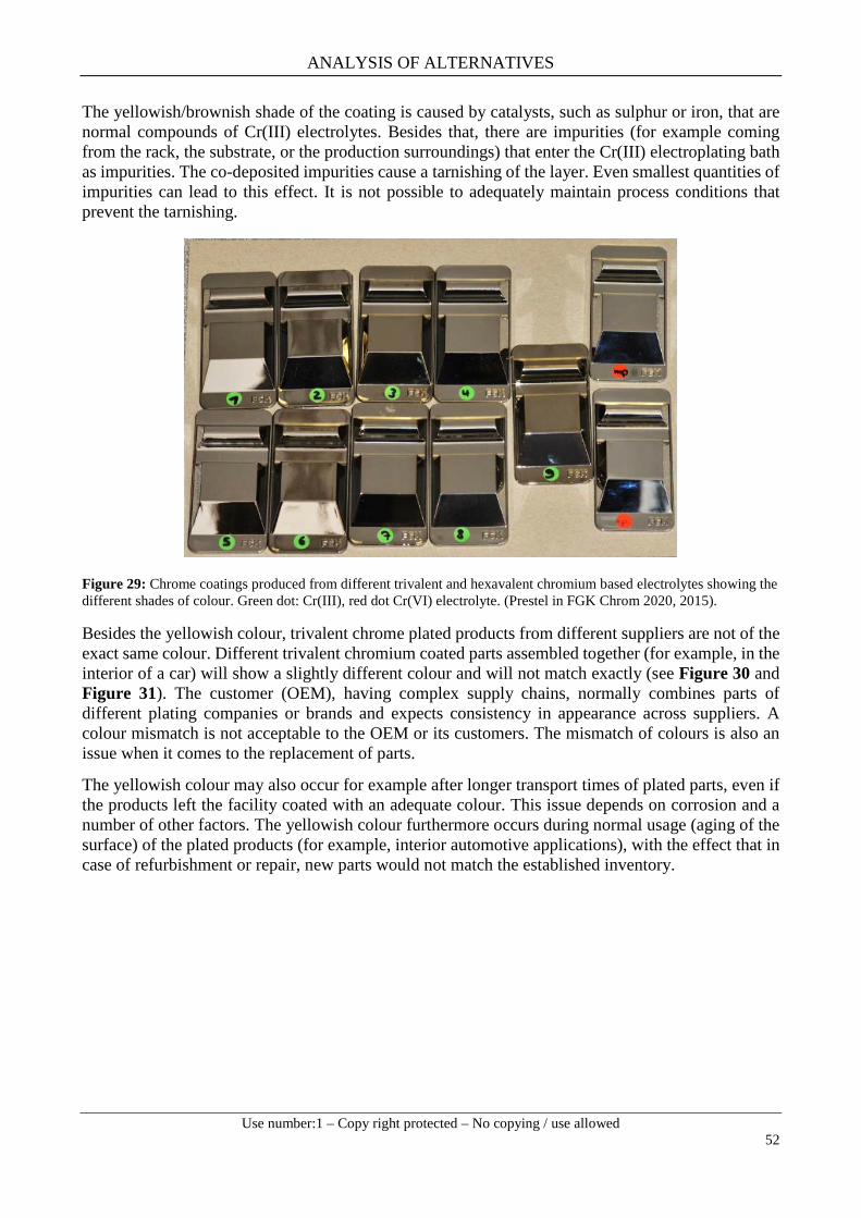
ANALYSIS OF ALTERNATIVES
Use number:1 – Copy right protected – No copying / use allowed
52
The yellowish/brownish shade of the coating is caused by catalysts, such as sulphur or iron, that are normal compounds of Cr(III) electrolytes. Besides that, there are impurities (for example coming from the rack, the substrate, or the production surroundings) that enter the Cr(III) electroplating bath as impurities. The co-deposited impurities cause a tarnishing of the layer. Even smallest quantities of impurities can lead to this effect. It is not possible to adequately maintain process conditions that prevent the tarnishing.
Figure 29: Chrome coatings produced from different trivalent and hexavalent chromium based electrolytes showing the different shades of colour. Green dot: Cr(III), red dot Cr(VI) electrolyte. (Prestel in FGK Chrom 2020, 2015).
Besides the yellowish colour, trivalent chrome plated products from different suppliers are not of the exact same colour. Different trivalent chromium coated parts assembled together (for example, in the interior of a car) will show a slightly different colour and will not match exactly (see Figure 30 and Figure 31). The customer (OEM), having complex supply chains, normally combines parts of different plating companies or brands and expects consistency in appearance across suppliers. A colour mismatch is not acceptable to the OEM or its customers. The mismatch of colours is also an issue when it comes to the replacement of parts.
The yellowish colour may also occur for example after longer transport times of plated parts, even if the products left the facility coated with an adequate colour. This issue depends on corrosion and a number of other factors. The yellowish colour furthermore occurs during normal usage (aging of the surface) of the plated products (for example, interior automotive applications), with the effect that in case of refurbishment or repair, new parts would not match the established inventory.

ANALYSIS OF ALTERNATIVES
Use number:1 – Copy right protected – No copying / use allowed
53
Figure 30: Colour differences between surfaces coated with a Cr(III) electrolyte and PoPAA which is performed with a Cr(VI) electrolyte (VDA in FGK Chrom 2020, 2015).
The long-time colour stability of coatings from Cr(III) electrolytes was examined in field tests on numerous different samples. The test results showed that the coatings from Cr(III) electrolytes became gradually darker, while the coatings from a chromium trioxide electroplating did not change colour at all. As a consequence, the overall aesthetic appearance and long-time colour stability clearly does not fulfil the requirements of the automotive sector at the current stage of development. Additionally, the colour of the plated product is highly dependent on the kind of electrolyte used. Due to the large variety of different parts assembled together per automobile, the different shades of colour result in a colour mismatch, as already described above. Unfortunately, the actual reasons for the change in colour over time are still unclear and specific test methods for the colour are not available.
Figure 31: Automotive supply chain visualising the exemplarily colour issue with Cr(III) coated parts. (VDA in FGK Chrom 2020, 2015, adapted).
Customer acceptance: Due to efforts achieved throughout the last years, Cr(III) electroplating is close to be accepted by the customers. Some OEM have started to test the finish on selected models.
Cr(III): colour differences depending on the system used
Cr(VI): almost no colour differences, despite use of different systems
Formulator
Tier 1Tier 1 Tier 1 Tier 1 Tier 1 Tier 1 Tier 1 Tier 1
Beschich
ter
Electroplate
r
Electroplate
r
Electroplater
Electropla
ter
Electro
plater
Electro
plater
Electroplate
r
Electroplate
r
Electroplater
Automobile Brands
Injec. Mould.Injec. Mould. Injec. Mould. Injec. Mould. Injec. Mould.Injec. Mould. Injec. Mould.
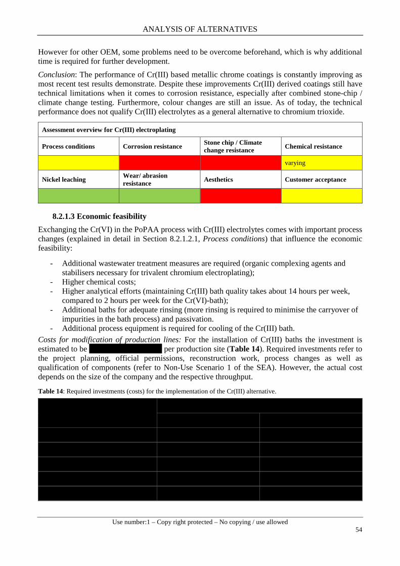
ANALYSIS OF ALTERNATIVES
Use number:1 – Copy right protected – No copying / use allowed
54
However for other OEM, some problems need to be overcome beforehand, which is why additional time is required for further development.
Conclusion: The performance of Cr(III) based metallic chrome coatings is constantly improving as most recent test results demonstrate. Despite these improvements Cr(III) derived coatings still have technical limitations when it comes to corrosion resistance, especially after combined stone-chip / climate change testing. Furthermore, colour changes are still an issue. As of today, the technical performance does not qualify Cr(III) electrolytes as a general alternative to chromium trioxide.
8.2.1.3 Economic feasibility Exchanging the Cr(VI) in the PoPAA process with Cr(III) electrolytes comes with important process changes (explained in detail in Section 8.2.1.2.1, Process conditions) that influence the economic feasibility:
- Additional wastewater treatment measures are required (organic complexing agents and stabilisers necessary for trivalent chromium electroplating);
- Higher chemical costs; - Higher analytical efforts (maintaining Cr(III) bath quality takes about 14 hours per week,
compared to 2 hours per week for the Cr(VI)-bath); - Additional baths for adequate rinsing (more rinsing is required to minimise the carryover of
impurities in the bath process) and passivation. - Additional process equipment is required for cooling of the Cr(III) bath.
Costs for modification of production lines: For the installation of Cr(III) baths the investment is estimated to be xxxxxxxxxxxxxxxxxx per production site (Table 14). Required investments refer to the project planning, official permissions, reconstruction work, process changes as well as qualification of components (refer to Non-Use Scenario 1 of the SEA). However, the actual cost depends on the size of the company and the respective throughput.
Table 14: Required investments (costs) for the implementation of the Cr(III) alternative.
Assessment overview for Cr(III) electroplating
Process conditions Corrosion resistance Stone chip / Climate change resistance Chemical resistance
varying
Nickel leaching Wear/ abrasion resistance Aesthetics Customer acceptance
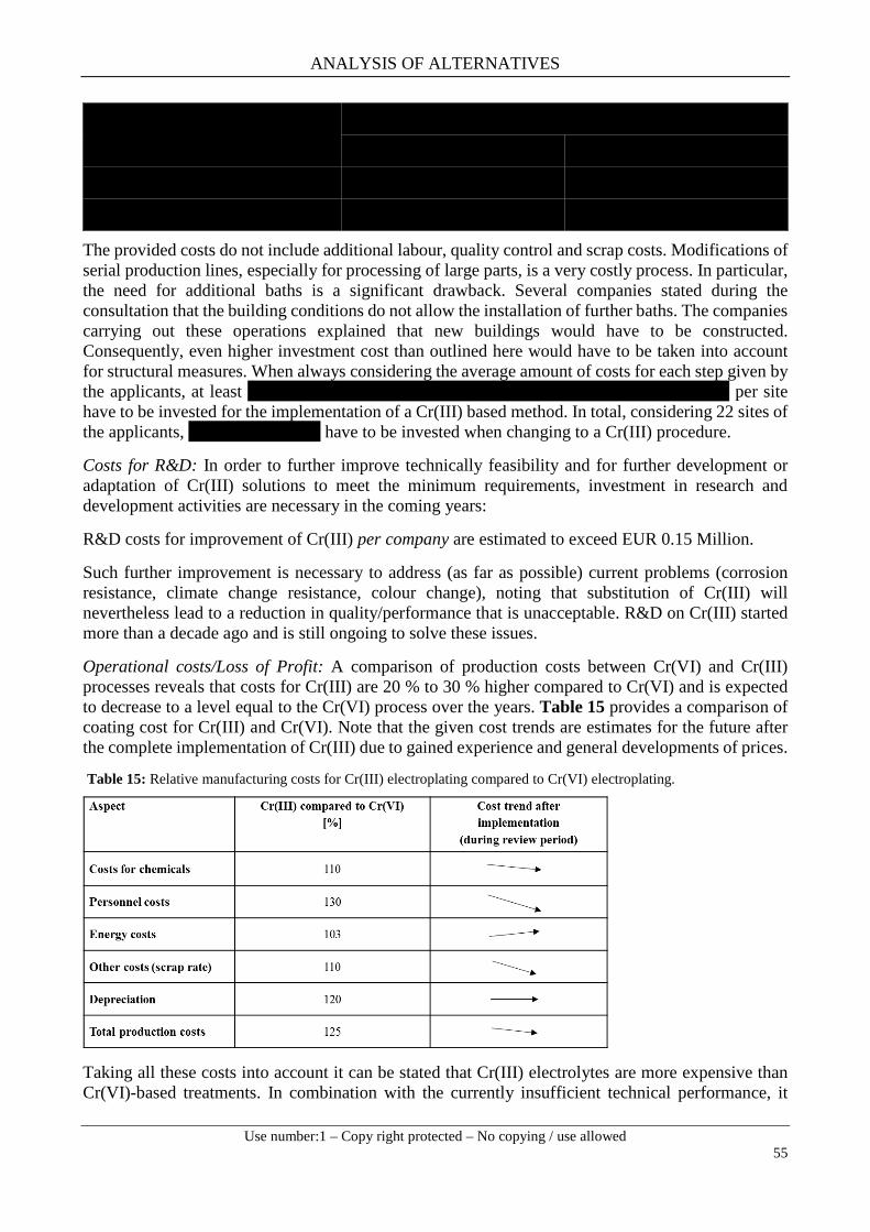
ANALYSIS OF ALTERNATIVES
Use number:1 – Copy right protected – No copying / use allowed
55
The provided costs do not include additional labour, quality control and scrap costs. Modifications of serial production lines, especially for processing of large parts, is a very costly process. In particular, the need for additional baths is a significant drawback. Several companies stated during the consultation that the building conditions do not allow the installation of further baths. The companies carrying out these operations explained that new buildings would have to be constructed. Consequently, even higher investment cost than outlined here would have to be taken into account for structural measures. When always considering the average amount of costs for each step given by the applicants, at least XXXXXXXXXXXXXXXXXXXXXXXXXXXXXXXXXXXXXX per site have to be invested for the implementation of a Cr(III) based method. In total, considering 22 sites of the applicants, xxxxxxxxxxxxxxx have to be invested when changing to a Cr(III) procedure.
Costs for R&D: In order to further improve technically feasibility and for further development or adaptation of Cr(III) solutions to meet the minimum requirements, investment in research and development activities are necessary in the coming years:
R&D costs for improvement of Cr(III) per company are estimated to exceed EUR 0.15 Million.
Such further improvement is necessary to address (as far as possible) current problems (corrosion resistance, climate change resistance, colour change), noting that substitution of Cr(III) will nevertheless lead to a reduction in quality/performance that is unacceptable. R&D on Cr(III) started more than a decade ago and is still ongoing to solve these issues.
Operational costs/Loss of Profit: A comparison of production costs between Cr(VI) and Cr(III) processes reveals that costs for Cr(III) are 20 % to 30 % higher compared to Cr(VI) and is expected to decrease to a level equal to the Cr(VI) process over the years. Table 15 provides a comparison of coating cost for Cr(III) and Cr(VI). Note that the given cost trends are estimates for the future after the complete implementation of Cr(III) due to gained experience and general developments of prices.
Table 15: Relative manufacturing costs for Cr(III) electroplating compared to Cr(VI) electroplating.
Taking all these costs into account it can be stated that Cr(III) electrolytes are more expensive than Cr(VI)-based treatments. In combination with the currently insufficient technical performance, it
ANALYSIS OF ALTERNATIVES
Use number:1 – Copy right protected – No copying / use allowed
56
cannot be considered a viable option for companies to lower the prices for articles plated with a Cr(III) solution to potentially gain better market access. Poorer quality/performance by concomitantly rising operational cost is not acceptable to suppliers and customers from the automotive sector. Impacts related to loss of profit resulting from increased manufacturing costs and higher reject rates amount to at least xxxxxxxxxxxxxxxx (refer to SEA) for the group of applicants.
Higher costs and shorter time intervals for maintenance are expected, since the whole process technology is more complex (more baths required, ion exchangers, prone electrodes, sensitive process parameters). In addition, analytical tests are getting more complicated and thus might not be performed in-house anymore. Further investments have to be considered for (re-)training of workers, due to additional process steps, such as manual regulation of additive additions not required for Cr(VI) electrolytes. Another important aspect is the need for more frequent daily quality tests, leading to increased personnel costs. Due to process-related variations of layer thicknesses and hues in the case of a Cr(III)-based method, more attention has to be particularly paid to quality aspects, which additionally leads to higher scrap rates (~xxxxxxx after process start, more than xxxxx after complete implementation) causing further costs.
With regard to the currently applied Cr(VI) passivation on Cr(III) coatings, this process based on two separate steps is less economically feasible compared to the chromium trioxide based process.
Cr(III) electroplating is the alternative to PoPAA main-treatment favoured by the automotive industry. Despite of significant efforts achieved over the last years, the overall maturity of the alternative to eliminate Cr(VI) from the plating process depends on the availability of a Cr(VI)-free etching pre-treatment. From an economic perspective the implementation of an entirely Cr(VI)-free plating-process is more reasonable than the stepwise replacement of the main-treatment and subsequently of the pre-treatment. A stepwise introduction is accompanied by full re-qualification of the coating at the OEMs, once when introducing the main-treatment and again when introducing the pre-treatment. From the economic perspective it is advisable to further develop the entire Cr(III) electroplating process until it is completely Cr(VI)-free, avoiding partial substitution.
Value added forgone: As described in the SEA the value added foregone for all sites with a xx month shutdown/downtime in connection with a transition to Cr(III) were calculated to be xxxxxxxxxxxxxxxx for the group of applicants.
8.2.1.4 Reduction of overall risk due to transition to the alternative Based on the available information on the substances used within this alternative (see Appendix 2.2.1), chromium (III) chloride would be the worst case with a classification as Skin Irrit. 2, Eye Irrit. 2, Acute Tox. In general, the trivalent electroplating processes are less toxic than chromium trioxide plating due to the oxidation state of the chromium. Cr(III) solutions do not pose serious air emission issues, but still pose the problems of disposal of stripping solutions (depending on the type of stripping solution) and exposure of staff to chrome dust during grinding.
In addition, there is a certain risk of Cr(VI) being generated during the plating process. This is why appropriate security precaution and process management has to be adopted to prevent the formation of Cr(VI). The bath chemistry typically also comprises a high concentration of boric acid, which is a SVHC substance (toxic for reproduction) included on the candidate list and currently on the 6th recommendation for inclusion in Annex XIV.
Another aspect to be mentioned is the significantly increased aerosol-formation during the Cr(III) process due to the inferior current yield compared to the Cr(VI) process.

ANALYSIS OF ALTERNATIVES
Use number:1 – Copy right protected – No copying / use allowed
57
Despite these facts, the transition from chromium trioxide to trivalent chromium constitutes a shift to less hazardous substances, however as at least one the used alternative substances is itself classified for mutagenicity and carcinogenicity, any replacements will need to be carefully evaluated on a case by case basis.
8.2.1.5 Availability The Cr(III) electroplating techniques, as well as different kinds of Cr(III) electrolytes are commercially available. Single Cr(III) coated products have been recently accepted by some automobile manufacturers for one car model (e.g., front grill from Peugeot A9 MiVi). However, the same demands are not valid for all OEMs, depending on the segment they serve. Importantly, these products are often not produced completely Cr(VI) free, as there is still a Cr(VI) pre- and post-treatment (passivation) necessary. In context with Cr(III) as an alternative, a process that is totally Cr(VI)-free does not yet exist. As stated in Section 8.2.1.2, Cr(III) electrolytes are a promising alternative and subject to further optimisation by formulators. However, they currently do not fulfil all OEM requirements from the automotive sector, especially under the required large scale production aspects with available capacities in Europe. Furthermore, no long-term field experience on the behaviour of parts for all interior and exterior uses is available at the current stage.
In addition to the demanding requirements that are not fulfilled at the current stage, capacities in Europe to cover the industry sector under large scale production are currently not available.
Following the R&D performed in the last couple of years, metallic chrome coatings from Cr(III) electrolytes have improved, but further development and testing is necessary to produce marketable Cr(III) coated products. Thereby, chromium sulphate has been chosen to be further followed. Additionally, the Cr(VI)-based post-treatment could be eliminated and colour stability reached (Figure 32).
Figure 32: Progress made and future Cr(III) development.
As a most realistic scenario, Cr(III) electrolyte would have to be further improved until sufficient technical performance in combination with similar colours can be produced on a stable basis. This would enable OEMs to implement changes in running serial products using Cr(III) and Cr(VI) derived parts on the same car.
After having managed technological feasibility, the Cr(III) alternative coatings require approval by the OEMs. Only after having passed the sector specific approval procedures can the sectors start transitioning from chromium trioxide electroplating to Cr(III) electroplating. At the current stage, it is not likely that Cr(III) based electroplating can be industrially used as a general alternative to chromium trioxide electroplating within required capacities within 12 years after the sunset date.
Chromium Chloride
Chromium Chloride and
Sulphate
Cr(VI) Post-Treatment
Colour Stability
Future Chromium Sulphate Development

ANALYSIS OF ALTERNATIVES
Use number:1 – Copy right protected – No copying / use allowed
58
8.2.1.6 Conclusion on suitability and availability for Cr(III) At the current stage of development, Cr(III) electroplating cannot be seen as a general alternative to chromium trioxide electroplating due to the following limitations.
- Technical performance of metallic chrome coatings derived from Cr(III) electrolytes is promising but still inconsistent at the current laboratory stage. As of today, not all of the OEMs’ requirements can be fulfilled;
- A special issue is that Cr(III) coated parts still show colour variations. The customer (OEM), having complex supply chains, normally combines parts of different plating companies or brands and expects consistency in appearance across suppliers. A colour mismatch is not acceptable to the OEM or its customers. The mismatch of colours is also an issue when it comes to the replacement parts;
- The compressive Cr(III) bath technology requires significant investments in terms of process line modifications and analytics. Production costs are 30 % higher than for chromium trioxide;
- No long-term experience exists for metallic chrome coatings derived from Cr(III).
In combination with the comparably higher production costs of the alternative and the insufficient technical performance as outlined above (yet while there is still a clear opportunity to address this from non-EU sources), Cr(III) cannot be considered as a viable alternative yet. It is not expected that Cr(III) based electroplating can be industrially used as a general alternative to chromium trioxide electroplating at required capacities within 12 years after the sunset date. Additionally, no complete chromium trioxide free process chain will be available for an even longer time, as the development of an alternative for chromium trioxide etching of plastic is at a lower level of maturity than the alternatives for the subsequent plating process.
Cr(III) electroplating is the alternative to PoPAA favoured by OEMs (due to its at least similar appearance to PoPAA-surfaces) and the applicants. Even though the alternative cannot be considered available yet, research on trivalent chromium electroplating is pursued with intensive engagement of the platers. The performance of the Cr(III)-coatings has increased over the last few years and is drawing closer to meeting the OEMs’ expectations. However, considerable time and investments are required to achieve this goal. An intensive discussion between the platers and the OEMs about open questions on quality expectations, ways of financing and strategies for implementation are necessary. Further time is required to additionally develop an adequate Cr(VI)-free etching pre-treatment in order to achieve an alternative process, that is completely Cr(VI)-free as it is the more practical approach to change the production process (meaning pre-treatment and main-treatment) in whole at once instead of a stepwise introduction (first main- then pre-treatment) which comes with extra qualification cycles.

ANALYSIS OF ALTERNATIVES
Use number:1 – Copy right protected – No copying / use allowed
59
8.2.2. Main treatment: Category 1 alternative: PVD-based processes
8.2.2.1 Substance ID and properties / process description Physical Vapour Deposition (PVD) is the general name for a variety of vacuum processes. Compared to PoPAA, the PVD-based processes require fundamentally different technology, but an etching pre-treatment is not required.
The PVD process starts with placing the coating material in solid (or rarely in a liquid) form in a vacuum or low pressure plasma environment. The coating material is vapourised by an electric arc or electron beam (Turi, 2006) and deposited, atom by atom, onto the surface of the material to be coated in order to build up a thin film. Nitrogen, oxygen or methane are used as gases, while argon is used for the formation of the plasma phase. Vapourising of the coating material can be conducted by different methods.
The conditions for PVD coatings are process specific and dependent on the substrate and applied coating. PVD coating temperatures are typically in the range between 180 °C to 450 °C. The coating time depends on a number of factors, such as coating thickness, spinning time of the part in the vacuum chamber, and the geometry of the part to be coated.
PVD layers can be deposited either as a single layer, by multi-layer deposition, with up to 2000 (very thin) single layers, or as an alloy consisting of different kinds of metals. The typical thickness of PVD coatings for plastic substrates lies between 0.05 and 0.5 µm. The PVD coating time for plastic substrates is typically between 20 and 30 minutes which is higher than for metal substrates. A temperature reduction is necessary due to the lower melting point of the substrate, so to achieve the same thickness, the coating time must be increased. In general, the throughput of parts depends on the size of the vacuum chamber and the geometry of the parts.
Different technologies are commercially available, either comprising a three-layer lacquer + PVD + lacquer, or a two-layer lacquer + PVD system.
All systems start with an initial lacquer layer. Depending on the respective lacquer + PVD system, this is typically a powder lacquer, a wet lacquer or an UV-lacquer.
Large R&D efforts have been conducted and are still ongoing on the technical feasibility of lacquer + PVD + lacquers that apply a metal chromium or aluminium coating by a PVD process as an intermediate layer (which is the most favoured PVD-based alternative). PVD-based processes are a valuable method for many different kinds of applications. However, for a potential replacement of PoPAA with PVD-based solutions some difficulties occur. This is one reason why the applicants would rather focus on trivalent chromium electroplating, as the most promising alternative to PoPAA, than on PVD-based processes. The assessment of PVD-based processes conducted in the following, focuses on three-layer-systems (lacquer-PVD-lacquer), if not stated otherwise.
A non-exhaustive overview of general information on substances used within this alternative and the risk to human health and the environment is provided in Appendix 2.2.2. This overview is focused on selected substances for the PVD process and not on the (potential) content of potentially used lacquers (due to the large variety). Nevertheless, certain types of lacquers may contain potentially harmful substances.
Recently, PVD is the focus of development at several companies, who claim that PVD could replace PoPAA in all applications within a short period of time. The applicants have put serious efforts into the assessment of these processes. All of the PVD-based processes currently at hand have been tested
ANALYSIS OF ALTERNATIVES
Use number:1 – Copy right protected – No copying / use allowed
60
by the applicants for suitability for PoPAA-parts in course of the preparation of this AfA. The test-protocols are available at the respective companies. The reasons why the PVD-techniques are not regarded as suitable for the applicants are presented in the following. The assessment comprises all information gathered throughout the extensive examinations. For the specific PVD-techniques developed by Oerlikon Balzers (embedded PVD for Design parts (ePD)), a PVD-technology named Cromatipic® (developed by Hauzer, SIDASA and GreenCoat) as well as Superchrome PVD coating as developed by Vergason Technology Inc., additional company specific information is provided in Table 16.
8.2.2.2 Technical feasibility Substrate compatibility/ Selective coating of 2K- and 3K-components: A number of different plastic substrates can be applied with a lacquer + PVD system, without the need for an etching pre-treatment step. However, an important limitation of this technology is that selective coating of a 2K- or 3K-component is not possible. Depending on size and design of the part, masking of the area that should not be coated is partly possible. The masking will be removed by the laser technique afterwards. This procedure is technically very demanding and has a high reject rate. Furthermore, more process steps – handling, masking, laser removal – are necessary and increase costs per part by 25 %. Another possibility would be to produce these parts separately which would have influences on the existing car manufacturing lines.
More component-parts are mainly used in electrical devices (e.g. illuminable/ illustrated climate control panels as in Figure 17 or Figure 18). Inside electrical devices, a metallic surface is not appropriate, due to the risk of electrical short-circuits caused by metal particles in the electronics. Therefore, PVD technology is not suitable for coating of such parts. To our knowledge there are currently no 2K- or 3K-parts coated with PVD.
Complex parts, like hand wheels for outlet nozzles (see Figure 18), are manufactured using 3 or 4 different types of plastics moulded through simultaneous injection. The entire part is processed using chromium trioxide, but the piece is only partly plated. To our knowledge this sophisticated technology is only implemented by a few companies in Europe. Due to the obvious advantage of the one-step process in contrast to the multi-step manufacturing of such parts in Asia, a competitive advantage arises. A not granted authorisation would shift this technology to countries outside the European Union.
Corrosion resistance: The corrosion resistance of PVD-based processes depends on the type of coating and differs with the type of deposited metal. In general, PVD chrome intermediate layers show a better corrosion resistance than PVD aluminium intermediate layers. Especially in regard to mechanical loads caused by stone chip, the corrosion resistance of lacquer + PVD + lacquer systems with PVD aluminium an intermediate layer is not sufficient for exterior automotive application requirements, as demonstrated by the results of stone chip testing.
Wear / abrasion resistance: In PVD-based coating systems with a final lacquer, the wear resistance of these coatings is clearly lower compared to a metallic chrome coating, as no lacquer is able to fulfil the same abrasion resistance as metallic chrome coatings from chromium trioxide. With regard to abrasion resistance, test results showed a totally abraded surface after 1000 cycles in scratch resistance test according to DIN ISO 20566 (car wash resistance test). The lower abrasion resistance is a result of the much lower hardness of the PVD-based systems. Therefore, the abrasion resistance does not fulfil the automotive sector requirements at the current stage of development of PVD-based coatings.

ANALYSIS OF ALTERNATIVES
Use number:1 – Copy right protected – No copying / use allowed
61
Chemical resistance: For parts subject to high continuous and/or recurring mechanical or chemical stress (e.g., from normal use or regular cleaning) of interior and exterior vehicle parts being exposed to environmental influences the performance is inconsistent. The performance depends on the exact kind of coating and on the chemicals used. As a consequence, the chemical resistance of these coatings for automotive applications cannot be fully evaluated given the early stage of development. However, tests have been conducted with PVD-based coatings. Two-layer systems without a protective third lacquer layer on top showed poor performance in laboratory testing. As depicted in Figure 33, the test-item for the two-layer system (PVD-Chrome without paint layer on top) showed severe abrasion after cleaning with chrome polish. In some spots the coating was completely worn off and the bare plastic substrate is laid open. The three-layer PVD coated item also showed abrasion after the chrome polishing procedure while the electroplated chrome part was not affected. The performance of the PVD-based coatings is clearly unacceptable for the applicants. The coatings also failed in the NSS-Test (according to PV 1200 /240 h) as exemplarily depicted in Figure 34.
Figure 33: Comparison of PVD and electroplated chrome (PoPAA) regarding chemical resistance for different test patterns (FGK, 2015).
Figure 34: PVD coated test plates after NSS.
ANALYSIS OF ALTERNATIVES
Use number:1 – Copy right protected – No copying / use allowed
62
Adhesion: Tests are ongoing on the adhesion of PVD-based processes. Currently, the adhesive properties of this kind of coating system are not sufficient for some OEMs. The lacquer coating of some systems delaminates after UV-exposure and in general, the adhesive properties of PVD deposited layers are not comparable with electrolytically deposited layers. In summary, the adhesion of PVD-based coatings for automotive applications does not fulfil the sector specific requirements at the current stage of development.
Weather proof: Sunlight resistance, colour stability, colour match, as well as the temperature change resistance of PVD-based systems are dependent on the respective coating system. During the consultation, R&D was stated to be ongoing. At the current stage, some systems, especially UV-lacquer systems, show a delamination of the lacquer after UV exposure. This was confirmed by an OEM that experienced significant adhesive failures during field testing of this coating system. As a consequence, the OEM went back to Cr(VI) and did not undertake further investments for this technology worldwide.
Complex geometries: According to current test results, the coating cannot be applied on all geometries with satisfying results (no sharp edges possible, optical appearance unsatisfying, see Figure 35). Further development is needed to overcome the issue.
Reusability/Recyclability: Another aspect to be mentioned is that PVD-based processes are extremely inefficient in terms of coating materials and lacquers. As the materials are sprayed onto the plastic parts, high amounts of material are spread inside the coating chamber as overspray. In that way high amounts of the coating and lacquering materials are lost and only a small percentage of the materials charged to the spraying facilities ends up on the plastic parts as a coating. It is impossible to reuse or recycle any of the overspray. Instead the material has to be removed from the chamber and disposed of appropriately. In contrast to that galvanic processes, as in PoPAA, which are much more material efficient, as the coating is only applied to the items immersed into the baths and the electrolytic solution is used over and over again.
Aesthetics: In general, the colour of PVD-based coatings is highly characterised by the deposited metal. As stated during the consultation, the typical appearance of coated surfaces have a characteristic wavy surface and show an orange peel effect instead of the bright and silvery-bluish appearance of a metallic chrome coating applied by chromium trioxide plating and as such do not meet OEM requirements connected to PoPAA. In addition, the metal feeling (cool touch) that is achieved with PoPAA is not achievable with PVD-based systems. Heat conductivity of the layer system is not high enough to achieve this effect. Therefore, PVD-based coatings do not fulfill the customers’ requirements associated with PoPAA.

ANALYSIS OF ALTERNATIVES
Use number:1 – Copy right protected – No copying / use allowed
63
Electroplated Chrome
PVD-Chrome

ANALYSIS OF ALTERNATIVES
Use number:1 – Copy right protected – No copying / use allowed
64
Figure 35: Comparison of PVD-chrome with electroplated Chrome. Left: electroplated chrome, right: PVD-Chrome (FGK, 2015).
Customer acceptance: As described above, the PVD-based coating systems do not fulfil the technical requirements that are determined by the OEMs in context with PoPAA. In contrast to Cr(III) electroplating, which is the potential alternative focused on by the applicants, PVD-coatings do not provide the cool metal touch that is typical for the PoPAA-parts. Additionally, the colour of these coatings is not acceptable to the OEM or its customers when assembled together with PoPAA-parts. In order to provide their customers with features close to those of PoPAA, PVD is not the alternative of choice for the applicants and their customers. Therefore, the implementation of PVD-facilities instead of the PoPAA facilities is not practical for the FGK members as they are likely to lose their customers to providers of PoPAA outside the EU.
Conclusions: The lacquer + PVD + lacquer technique is technically not feasible as a general alternative to chrome electroplating at the current stage of development. Effects of the lacquer on the aesthetic appearance, together with a missing metal feeling, do not fulfil the high aesthetic requirements of the automotive sector. Compared to the technical performance of Cr(III) electroplating, PVD-based processes are not the preferred option for the replacement of Cr(VI) in PoPAA. Therefore R&D conducted by the applicants has focused on Cr(III) electroplating for several years.
Assessment overview for PVD-based systems system
Selective coating of 2K, 3K components
Corrosion resistance
Chemical resistance
Wear / abrasion resistance
Reusability/ recyclability
Inconsistent
Adhesion Weather proof Aesthetics Customer acceptance
The applicants highlight that the technical assessment presented here includes the different PVD processes as developed by the companies mentioned above. However, additional company specific information is presented in Table 16 below.
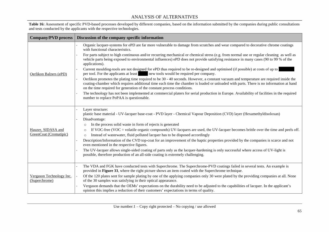
ANALYSIS OF ALTERNATIVES
Use number:1 – Copy right protected – No copying / use allowed
65
Table 16: Assessment of specific PVD-based processes developed by different companies, based on the information submitted by the companies during public consultations and tests conducted by the applicants with the respective technologies.
Company/PVD process Discussion of the company specific information
Oerlikon Balzers (ePD)
- Organic lacquer-systems for ePD are far more vulnerable to damage from scratches and wear compared to decorative chrome coatings with functional characteristics.
- For parts subject to high continuous and/or recurring mechanical or chemical stress (e.g. from normal use or regular cleaning as well as vehicle parts being exposed to environmental influences) ePD does not provide satisfying resistance in many cases (90 to 99 % of the applications).
- Current moulding-tools are not designed for ePD thus required to be re-designed and optimised (if possible) at costs of up to xxxxxxxx per tool. For the applicants at least xxxxx new tools would be required per company.
- Oerlikon promotes the plating time required to be 30 - 40 seconds. However, a constant vacuum and temperature are required inside the coating-chamber which requires additional time each time the chamber is loaded or unloaded with parts. There is no information at hand on the time required for generation of the constant process conditions.
- The technology has not been implemented at commercial platers for serial production in Europe. Availability of facilities in the required number to replace PoPAA is questionable.
Hauzer, SIDASA and GreenCoat (Cromatipic)
- Layer structure: plastic base material - UV-lacquer base-coat - PVD layer - Chemical Vapour Deposition (CVD) layer (Hexamethyldisoloxan)
- Disadvantage: o In the process solid waste in form of rejects is generated o If VOC-free (VOC = volatile organic compounds) UV-lacquers are used, the UV-lacquer becomes brittle over the time and peels off. o Instead of wastewater, fluid polluted lacquer has to be disposed accordingly
- Description/Information of the CVD top-coat for an improvement of the haptic properties provided by the companies is scarce and not even mentioned in the respective figures.
- The UV-lacquer allows single-sided coating of parts only as the lacquer-hardening is only successful where access of UV-light is possible, therefore production of an all-side coating is extremely challenging.
Vergason Technology Inc. (Superchrome)
- The VDA and FGK have conducted tests with Superchrome. The Superchrome-PVD coatings failed in several tests. An example is provided in Figure 33, where the right picture shows an item coated with the Superchrome technique.
- Of the 120 plates sent for sample plating by one of the applying companies only 30 were plated by the providing companies at all. None of the 30 samples was satisfying in their optical appearance.
- Vergason demands that the OEMs’ expectations on the durability need to be adjusted to the capabilities of lacquer. In the applicant’s opinion this implies a reduction of their customers’ expectations in terms of quality.
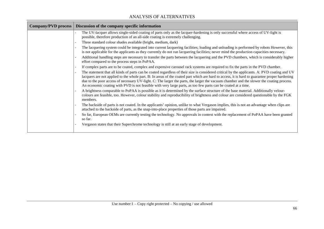
ANALYSIS OF ALTERNATIVES
Use number:1 – Copy right protected – No copying / use allowed
66
Company/PVD process Discussion of the company specific information - The UV-lacquer allows single-sided coating of parts only as the lacquer-hardening is only successful where access of UV-light is
possible, therefore production of an all-side coating is extremely challenging. - Three standard colour shades available (bright, medium, dark) - The lacquering system could be integrated into current lacquering facilities; loading and unloading is performed by robots However, this
is not applicable for the applicants as they currently do not run lacquering facilities; never mind the production capacities necessary. - Additional handling steps are necessary to transfer the parts between the lacquering and the PVD chambers, which is considerably higher
effort compared to the process steps in PoPAA. - If complex parts are to be coated, complex and expensive carousel rack systems are required to fix the parts in the PVD chamber. - The statement that all kinds of parts can be coated regardless of their size is considered critical by the applicants. A: PVD coating and UV
lacquers are not applied to the whole part. B: In areas of the coated part which are hard to access, it is hard to guarantee proper hardening due to the poor access of necessary UV-light. C: The larger the parts, the larger the vacuum chamber and the slower the coating process. An economic coating with PVD is not feasible with very large parts, as too few parts can be coated at a time.
- A brightness comparable to PoPAA is possible as it is determined by the surface structure of the base material. Additionally velour-colours are feasible, too. However, colour stability and reproducibility of brightness and colour are considered questionable by the FGK members.
- The backside of parts is not coated. In the applicants’ opinion, unlike to what Vergason implies, this is not an advantage when clips are attached to the backside of parts, as the snap-into-place properties of those parts are impaired.
- So far, European OEMs are currently testing the technology. No approvals in context with the replacement of PoPAA have been granted so far.
- Vergason states that their Superchrome technology is still at an early stage of development.

ANALYSIS OF ALTERNATIVES
Use number:1 – Copy right protected – No copying / use allowed
67
8.2.2.3 Economic feasibility Extensive investigation on the economic feasibility of PVD-based processes was conducted in course of the preparation of this AfA. For detailed insight into the calculations the reader is referred to the SEA.
Investment costs: Installation of completely new production lines is required. Estimations on the costs for technical implementation is provided in Table 17 below.
Table 17: Required investments (costs) for the implementation of the PVD alternative.
It is estimated that building up capacities with this technology would take 5-6 years including investment costs of at least xxxxxxxxxxxxx per site (average xxxxxxxxxxxxx). Those costs account for project planning, official permissions, dismantling and reconstruction work, installation and start-up of PVD equipment, tool modification as well as qualification of components (refer to Non-Use Scenario 2 of the SEA). Regarding the average effort needed to introduce the currently not technically feasible PVD technique, at xxxxxxxxxxxxxxxxxxxxxxxxxxxxxxxxxxxxxxxxxxxx qualification costs) per site have to be invested. The total sum considering all 22 sites of the applicants would be at least xxxxxxxxxxxxxxx in case the PVD technique should be introduced.
An important part of implementation costs for PVD as potential alternative is the investment necessary to buy and install PVD machines. The number of PVD machines required to replace Cr(VI) based PoPAA at the applicants´ sites depends on the capacity of available machines. Investment costs can then be estimated based on costs per machine. Due to experience made with a previous AfA and especially as PVD technology providers submitted several comments during public consultations in the past, the applicants have contacted the company Oerlikon Balzers and asked for information regarding price of PVD machines, capacity of PVD machines, availability with regard to guaranteed delivery times and whether all parts produced by the applicants can be plated with PVD machines taking into account shape and size. However, until submission of this AfA the applicants so far did not receive any response or information from Oerlikon Balzers.

ANALYSIS OF ALTERNATIVES
Use number:1 – Copy right protected – No copying / use allowed
68
Against this background, it was only possible to calculate a theoretical number of required PVD machines based on publicly available information and information provided by PVD suppliers Vergason Technology Inc. (Superchrome PVD coating) and Oerlikon Balzers (ePD Technology) during previous public consultations.
The following paragraph sums up the calculation presented in detail in the SEA. In order to allow comparison of capacities, the idealised capacity of electroplating lines operated by the applicants has been estimated. An idealised surface area of xxxxxxxxxxxx for the plating lines of all applicants within one year has be calculated. For a SUPERCROME coating line an idealised capacity of 256 m2/day (24 h operation per day) and 68,352 m2/year, (assuming 267 working days) was calculated. For the Oelikon Balzers PVD-process these figures were foud to be 1,440 m2/day and 384,480 m2/year per coating line. Based on these figures, at least xxxx (Oerlikon Balzers) to xxxx (Superchrome) coating lines would be required in order to reach the required surface area coated by the applicants. Considering the minimal amount of EUR 2 Million for a PVD machine including painting line and based on the conservative estimation of xxxx required machines, xxxxxxxxxxxxx have to be invested by the applicants in order to guarantee the current productivity. Value added forgone: As described in the SEA the value added foregone for all sites with a xxx month shutdown/downtime in connection with a transition to PVD were calculated to be xxxxxxxxxxxxxxx. Operational costs/Loss of Profit: A non-uniform and mostly smaller surface thickness compared to Cr(VI) based surfaces has to be considered in conjunction with the fact that in total several layers depending on the applied PVD method are deposited on the components. In order to avoid fissuring in the final application due to these little surface thicknesses the in-mold assemblies have to be modified in a costly way or even substituted. Furthermore, it has to be highlighted again that only a fractional amount of components can be processed by PVD techniques due to limited sizes of the PVD chambers and that a selective plating of 2K/3K components is not possible. In order to process the whole portfolio, chambers with dimensions of approximately 1.2 x 1.5 m would be needed. According to applicants, these machines cannot be delivered shortly both in required sizes and units. Higher energy costs represent another important aspect, which has to be taken into account. This claim can be underpinned by the fact that PVD is a high-vacuum process and, depending on the component to be coated, different temperatures are required. A cost increase for employees should not be neglected as well. On the one hand, workers have to be reskilled in order to be able to optimize parameters or handle process-related problems. On the other side, expensive and rare experts of this niche technology have to be hired. Finally, the afore-mentioned variations in quality due to a high sensitivity towards surface defects lead to a higher scrap rate (xxxxx) and thus to higher disposal costs.
An increase of production costs of xxxxx due to the change to PVD processes is estimated by the clients for the first 3 years of use. As a consequence of gained experience concerning procedural aspects, such as correct adjustment of process parameters leading gradually to less scrap rates and increasing expertise of workers, the additional costs are reduced to xxxxxxxxxxx for the years 4-6 and 7-12, respectively.
As the plastic substrates have rather lower melting temperatures, PVD coatings are applied with low and constant temperature methods. These reduced temperatures typically require long coating times to achieve the required thickness of the coating. Furthermore, PVD-based processes are run in vacuum chambers. Considerable additional time is required to adjust temperature and pressure conditions each time accordingly before and after the plating process for unloading and loading the coating chamber, resulting in higher operational costs. Further factors are that the coating costs for

ANALYSIS OF ALTERNATIVES
Use number:1 – Copy right protected – No copying / use allowed
69
PVD metal are significantly higher, because no wet-in-wet coating is possible, and at the current stage full automation is not possible, requiring extra handling steps. Additionally, due to the complexity of PVD-based systems, maintenance costs are very high. Table 18 gives an overview on the factors influencing the operational costs for PVD-based processes and the respective estimated cost trends.
Table 18: Aspects influencing process costs for the implementation of PVD compared to Cr(VI) and estimated cost trends during the review period.
8.2.2.4 Reduction of overall risk due to transition to the alternative As the alternative is not technically feasible, only classification and labelling information of substances and products reported during the consultation were reviewed for comparison of the hazard profile. Based on the available information on the substances used within this alternative (see Appendix 2.2.2), titanium nitride would be the worst case with a classification as Flam. Sol. 2, Skin Irrit. 2 and Eye Irrit. 2. However it must be considered that UV-lacquers as used for PVD coatings contain photosensitive radical formers. As soon as exposed to light, a chain reaction which leads to the formation of polymers, is induced. In this context the radicals can attack other lacquer constituents as well as human tissue, where they can cause serious damage even leading to the formation of cancer through uncontrolled cell proliferation. Some of the substances known in the application in UV-lacquers are even rated as SVHC. Furthermore there is a risk that UV radiation does not harden the entire resin due to incomplete penetration. Components of unhardened resins are toxic and can get to the end-consumer and into the environment.
Therefore switching from PoPAA to PVD does not necessarily constitute a shift to less hazardous substances.
8.2.2.5 Availability Different PVD-based processes have been tested and R&D is still ongoing, as PVD-based alternatives are one of the most promising alternatives to chromium trioxide electroplating at the current stage of development.
Lacquer + PVD + lacquer systems (with either applying a chrome or aluminium coating) are already in use for some interior automotive applications but the evaluation of the performance (especially the

ANALYSIS OF ALTERNATIVES
Use number:1 – Copy right protected – No copying / use allowed
70
long-term performance) of the coatings is ongoing. In addition, R&D and development of these kinds of coatings for future use in exterior automotive applications is ongoing as well. As stated during the consultation, no sufficient capacities are available on the market for the broad application of lacquer + PVD + lacquer systems (with either applying a chrome or aluminium coating). The transition to this alternative would demand the set-up of new production lines across the market, which would result in high investments costs.
Based on the information provided in in Section 8.2.2.3 the short-term availability of a sufficient number of machines is doubtful. It is claimed by Oerlikon Balzers that the assembling, installation and ramp-up for a single machine takes around 18-24 months after placing of an order (Oerlikon Balzers 2015). In case of a plurality of simultaneous requests this time estimation might be significantly prolonged, if at all possible.
Please note that after the public consultation of the CTAC AfA, the applicants have contacted the company Oerlikon Balzers and asked for information regarding price of PVD machines, capacity of PVD machines, availability with regard to guaranteed delivery times and whether all parts produced by the applicants can be plated with PVD machines taking into account shape and size. However, until submission of this AfA the applicants did not receive any response or information from Oerlikon Balzers.
Vergason Technology Inc. declares that systems can be used six months after the order. The current capacity allows the company to produce 30-50 batch machines per year. Thus, at least xxxxxx would pass for the delivery of over xxxxxxxxxxx assuming the maximal producible amount of machines and neglecting capacity and financial limitations as well as orders from other electroplaters not included in the group of applicants.
Further technological development of PVD-based processes, and especially of the lacquer + PVD + lacquer systems, is necessary before a coating system may become technically comparable to metallic chrome coatings applied using chromium trioxide as electrolyte. It was stated during the consultation that at least 2 years of intensive R&D are necessary for this step. The coating process then requires sector specific approval. This approval would be given by the OEM for the automotive sector. Finally, and only after passing the approval procedure, the applicants could start to increase the required production capacity. Assuming that it would be technically feasible to replace the PoPAA-process with a PVD-process, it is not realistic that the providers of PVD production equipment could supply the European market with enough installations to maintain the required production capacity.
In total, it is not likely that PVD-based processes could be industrially used as a general alternative to functional plating using chromium trioxide electroplating within 12 years after the sunset date.
8.2.2.6 Conclusion on suitability and availability for Alternative 2 PVD-based coating systems are already in use for some interior automotive applications. It is important to note, that these following applications are not within the scope of this AfA.
- Reflector housings (no corrosion resistance necessary, as closed system); - Radar permeable emblems in the front area of the vehicle, which were always applied to the
back side of a selectively screened polycarbonate disc by PVD.-Thereby, the PVD layer is not connected to the car body shell but protected in the inside against wear and corrosion exposures;
- Steering wheel emblems are partially coated by PVD-systems, if produced from non-galvanisable thermoplastic elastomer-plastics (TPE). No exterior applications. All other
ANALYSIS OF ALTERNATIVES
Use number:1 – Copy right protected – No copying / use allowed
71
parts of the steering wheel are manufactured from plastics and authentic chrome, because of the important considerations of metallic haptics and perception of value.
At the current stage of development, PVD-based systems cannot be seen as a general alternative to chromium trioxide electroplating due to the following limitations.
- Technical performance of coatings derived from this technology is insufficient for several crucial parameters. As of today, the OEMs’ requirements cannot be fulfilled;
- A special issue is that the metal feeling (cool touch) of this kind of coating is not available and therefore not fulfilling the customer’s requirements. Further aesthetic requirements are not in line with customers’ expectations. Generally, the colour of these coatings is not acceptable to the OEM or its customers. This mismatch of colours is also an issue when it comes to the replacement parts;
- Coating of 2K/3K parts is not possible; - The compressive PVD technology requires significant investments in terms of process
technology; - Experience and expertise at hand at the applicants’ companies are related to galvanic
processes; - No long-term experience exists.
In combination with the comparably higher investment and production costs of the alternative and the insufficient technical performance as outlined above, this technology cannot be considered as viable alternatives. Consultations by the applicants revealed that, depending on the company, PVD-based processes could be an alternative in the future for only 1-10 % of all PoPAA-parts. However, with Cr(III)-electroplating the whole range of PoPAA-parts can be coated, which is why Cr(III) electroplating is the alternative favoured by the applicants and their customers.
8.2.3. Main treatment: Category 2 alternatives The assessment for those methods rated as category 2 alternatives, which might be suitable for niche applications only but not as a general alternative for the Cr (VI) main treatment of PoPAA is provided below in Table 19.
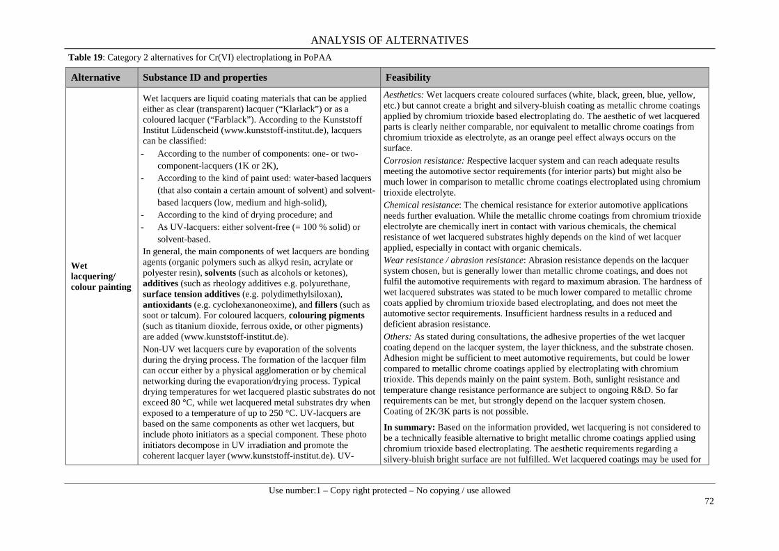
ANALYSIS OF ALTERNATIVES
Use number:1 – Copy right protected – No copying / use allowed
72
Table 19: Category 2 alternatives for Cr(VI) electroplationg in PoPAA
Alternative Substance ID and properties Feasibility
Wet lacquering/ colour painting
Wet lacquers are liquid coating materials that can be applied either as clear (transparent) lacquer (“Klarlack”) or as a coloured lacquer (“Farblack”). According to the Kunststoff Institut Lüdenscheid (www.kunststoff-institut.de), lacquers can be classified: - According to the number of components: one- or two-
component-lacquers (1K or 2K), - According to the kind of paint used: water-based lacquers
(that also contain a certain amount of solvent) and solvent-based lacquers (low, medium and high-solid),
- According to the kind of drying procedure; and - As UV-lacquers: either solvent-free (= 100 % solid) or
solvent-based. In general, the main components of wet lacquers are bonding agents (organic polymers such as alkyd resin, acrylate or polyester resin), solvents (such as alcohols or ketones), additives (such as rheology additives e.g. polyurethane, surface tension additives (e.g. polydimethylsiloxan), antioxidants (e.g. cyclohexanoneoxime), and fillers (such as soot or talcum). For coloured lacquers, colouring pigments (such as titanium dioxide, ferrous oxide, or other pigments) are added (www.kunststoff-institut.de). Non-UV wet lacquers cure by evaporation of the solvents during the drying process. The formation of the lacquer film can occur either by a physical agglomeration or by chemical networking during the evaporation/drying process. Typical drying temperatures for wet lacquered plastic substrates do not exceed 80 °C, while wet lacquered metal substrates dry when exposed to a temperature of up to 250 °C. UV-lacquers are based on the same components as other wet lacquers, but include photo initiators as a special component. These photo initiators decompose in UV irradiation and promote the coherent lacquer layer (www.kunststoff-institut.de). UV-
Aesthetics: Wet lacquers create coloured surfaces (white, black, green, blue, yellow, etc.) but cannot create a bright and silvery-bluish coating as metallic chrome coatings applied by chromium trioxide based electroplating do. The aesthetic of wet lacquered parts is clearly neither comparable, nor equivalent to metallic chrome coatings from chromium trioxide as electrolyte, as an orange peel effect always occurs on the surface. Corrosion resistance: Respective lacquer system and can reach adequate results meeting the automotive sector requirements (for interior parts) but might also be much lower in comparison to metallic chrome coatings electroplated using chromium trioxide electrolyte. Chemical resistance: The chemical resistance for exterior automotive applications needs further evaluation. While the metallic chrome coatings from chromium trioxide electrolyte are chemically inert in contact with various chemicals, the chemical resistance of wet lacquered substrates highly depends on the kind of wet lacquer applied, especially in contact with organic chemicals. Wear resistance / abrasion resistance: Abrasion resistance depends on the lacquer system chosen, but is generally lower than metallic chrome coatings, and does not fulfil the automotive requirements with regard to maximum abrasion. The hardness of wet lacquered substrates was stated to be much lower compared to metallic chrome coats applied by chromium trioxide based electroplating, and does not meet the automotive sector requirements. Insufficient hardness results in a reduced and deficient abrasion resistance. Others: As stated during consultations, the adhesive properties of the wet lacquer coating depend on the lacquer system, the layer thickness, and the substrate chosen. Adhesion might be sufficient to meet automotive requirements, but could be lower compared to metallic chrome coatings applied by electroplating with chromium trioxide. This depends mainly on the paint system. Both, sunlight resistance and temperature change resistance performance are subject to ongoing R&D. So far requirements can be met, but strongly depend on the lacquer system chosen. Coating of 2K/3K parts is not possible.
In summary: Based on the information provided, wet lacquering is not considered to be a technically feasible alternative to bright metallic chrome coatings applied using chromium trioxide based electroplating. The aesthetic requirements regarding a silvery-bluish bright surface are not fulfilled. Wet lacquered coatings may be used for

ANALYSIS OF ALTERNATIVES
Use number:1 – Copy right protected – No copying / use allowed
73
Alternative Substance ID and properties Feasibility lacquers have a broad application range and are commonly used in the printing industry.
interior automotive applications, in locations where the aesthetic criteria are less relevant. For exterior applications abrasion resistance and corrosion resistance need improvement.
Electroless nickel plating
Electroless nickel plating is an auto-catalytic reduction that deposits a metallic nickel layer on a substrate such as a metal or plastic. No electric current is involved in the coating process. Autocatalytic reduction is a chemical reaction in which the substrate acts as a catalyst, causing ions to continuously deposit onto the substrate. The most commonly used electroless nickel plating process produces a nickel coating with phosphor (Ni-P). Another version with less common uses is nickel-boron (Ni-B) coating and will not be discussed further in this context. Electroless nickel plating is performed by dipping the parts to be coated in an electrolytic aqueous solution containing the nickel source (for example nickel sulphate), reducing agent (for example sodium hypophosphite, borohydrite) and complexing agent (for example carboxylic acids or amines). The process depends on the presence of the reducing agent, which reduces the metallic ions in the electroless plating solution to form a coating. The complexing agent is necessary to increase the phosphite solubility of the reducing agent and to regulate the reaction rate. A non-exhaustive overview on general information on substances used within this alternative and the risk to human health and the environment is provided in Appendix 2.1.4.
Corrosion resistance: As stated during the consultation phase of CTAC, the corrosion resistance of electroless nickel coatings does not meet the automotive requirement. Electroless nickel coated parts did not pass the (company specific) 48 h CASS test. Chemical resistance: It was stated during the consultation in CTAC that the chemical resistance of electroless nickel coatings is sufficient and meets the overall automotive requirements. Wear resistance / abrasion resistance: The abrasion resistance of electroless nickel layers was stated to be sufficient for automotive applications given the hardness of the coatings. Aesthetics: The bright silvery-bluish appearance which is required for PoPAA cannot be reached with an electroless nickel layer. The electroless nickel coating is only a functional, not a decorative finish. The electroless nickel coatings may be slightly affected by corrosion, resulting in a reduced brightness and a yellowish appearance of the surface. This creates a colour match problem with other metallic surfaces, and makes it incompatible with numerous other parts that are assembled for one car.
In summary: Electroless nickel coatings are not technically feasible as an alternative to conventional coatings applied by electroplating with chromium trioxide. The aesthetic requirements for PoPAA are clearly not fulfilled. The corrosion resistance does not meet the automotive requirements.
ANALYSIS OF ALTERNATIVES
Use number:1 – Copy right protected – No copying / use allowed
74
9. OVERALL CONCLUSIONS ON SUITABILITY AND AVAILABILITY OF POSSIBLE ALTERNATIVES
Plastics are common substrates for numerous applications in the automotive industry due to several beneficial properties. The low weight compared to metal contributes to the overall weight reduction of vehicles, thus resulting in a lower fuel consumption and consequently less CO2 emissions.
In this AfA, two main potential alternatives have been considered for the purpose of replacing chromium trioxide in Plating on Plastics for Automotive Applications (PoPAA). Chromium trioxide is a crucial compound in the electroplating process. The final coated products, which are free from Cr(VI), are used in a large variety of applications in the automotive industry. The applicants in total operate 22 sites in different European countries (e.g., Germany, Spain, Slovakia, Czech Republic).The number of plastic part types produced for the automotive industry ranges between approximately xxxxxxxxxxxxxxxxxxx. In total, the applicants produce xxxxxxxxxxxxxxxxxxxxxxx xxxxxxx.
PoPAA is usually performed to produce a surface that meets the high requirements that are predefined by the OEMs regarding functionality (e.g., being highly durable under aggressive and demanding conditions) and aesthetics (high-class, valuable, top-quality appearance). Furthermore, PoPAA is a valuable technology applied for selective coating of parts, which are fabricated of two, three or more plastic materials (so-called 2K- or 3K-parts). These 2K/3K parts are the result of a special moulding technique which allows the simultaneous injection of different plastic materials of which at least one component is not able to be coated with the PoPAA process. This is of particular importance to European suppliers to retain a competitive technological advantage over non-EEA suppliers, e.g. from Asia or the NAFTA countries. Over the last years the increasing demand for multicomponent applications has made this a rapidly growing market.
The PoPAA process is complex and typically involves numerous steps, such as etching pre-treatment and several intermediate plating steps, followed by the chrome electroplating process (main process). The etching pre-treatment step cannot be separated or individually modified without impairing the overall process or properties of the final product. Compatibility and technical performance of the overall system are therefore considerations of primary importance for material specification.
As of today, only the use of chromium trioxide enables the aforementioned combination of process and product specific functionalities as described in detail in Section 4.4.
The automotive supply chain consists of several levels and is rather complex. In reality, there are around seven tiers of suppliers within the value added chain. German OEMs in the automotive sector have been recognised worldwide as first class producers of vehicles. Over the past 12 years the premium segment has increased relative to all other segments and in absolute numbers. The applicants deliver the major share of their products to European OEMs and automotive suppliers. A strong increase of the demand of chrome-plated plastic components, especially in the automotive sector, is expected in the near future. This can be explained by a general growth of the automotive market, particularly in Asian countries, and by the fact that these elements lead to an enormous reduction of weight and thus to a major saving of fuel costs when integrated into the vehicle.
Introducing new materials into the automotive market is a complex process, involving multiple phases and checks. Safety is the main driver for this. In the case of replacing chromium trioxide, all affected components must be revalidated using alternative materials. Revalidating must take place according to the demanding surface requirements of the automotive industry. Importantly, these are defined by the OEMs, not by the platers themselves. Over long years of development the OEMs have created

ANALYSIS OF ALTERNATIVES
Use number:1 – Copy right protected – No copying / use allowed
75
very specific and unique requirements for exterior and interior vehicle parts, including very precise expectation on the layer systems with which the parts are coated. For instance, the OEMs have extended the guarantees for product surfaces in favour of the end customer. Therefore, in the course of the last years the requirements on the surface performance have been drastically increased by the OEMs. It is the platers’ task to come up with solutions to comply with these expectations.
With regard to both the highly complex nature of supply chains in the automotive industry and the lifetime of vehicles, planning reliability is crucial. Average life cycles of an automobile model is about 22 years, comprising 3-5 years development time, 7 years of production and at least a 10 year service life, during which there is a need to guarantee availability of spare parts (see Figure 36). Realistically, changes to a vehicle model can only be made in a certain period of time, which decreases rapidly after type-approval by a certified body in the early stages of new model development.
Figure 36. Typical life-time of a car model (According to VDA in FGK Chrom 2020, 2015)
Potential alternatives for etching of plastic as a pre-treatment are technically not feasible at the current stage of development. Additional R&D is necessary to adjust these processes to each other to finally meet the industry requirements. It is not expected that alternatives to plastic etching are technically feasible before 12 years after the sunset date, and even more years might be needed.
The most promising alternatives to PoPAA are trivalent chromium electroplating and PVD-based processes. Intensive R&D has been performed over many years and is still ongoing for these potential alternatives. Technical improvement of these potential alternatives has been iseachieved in recent years, especially for Cr(III), which for several reasons is the potential alternative favoured by the applicants and their customers. However, the alternatives are currently not technically feasible and cannot be considered available to replace chromium trioxide as a commercial application at the current stage of development. The following Table 20 summarises the limitations of the alternatives.

ANALYSIS OF ALTERNATIVES
Use number:1 – Copy right protected – No copying / use allowed
76
Table 20: Comparison of the most promising potential alternatives to PoPAA.
Alternative Current technical and economic limitations why alternative cannot be considered as replacement for PoPAA
1
Cr(III) electroplating (including a Cr(VI)-free pre-treatment)
- Technical performance is inconsistent at the current laboratory stage. As of today, the entirety of OEMs’ requirements cannot be fulfilled;
- Despite of significant improvements, Cr(III) coated parts still show colour variations. Colour mismatch is not acceptable to the OEM or its customers. The mismatch of colours is also an issue when it comes to the replacement parts.
- Cr(VI)-free etching pre-treatment is required. An adequate Cr(VI)-free pre-treatment does not exist yet.
- Only a full conversion of the PoPAA process into a completely Cr(VI)-free treatment is regarded feasible (Qualification cycle to be passed twice).
- For metallic chrome coatings derived from Cr(III), no long-term experience regarding life-time quality exists.
- Introduction and industrialisation of Cr(III) requires significant investments in terms of process line modifications and analytics, in total, at least xxxxxxxxxxxxx and an approximate timeframe of 12 years after sunset date.
Additional time for R&D, qualification and planning is required to implement this alternative.
Results of assessment of etching with potassium permanganate (Section 8.1.1.)
Technical feasibility Economic feasibility Risk reduction Availability
Results of assessment of the Cr(III)-electroplating step (Section 8.2.1.):
Technical feasibility Economic feasibility Risk reduction Availability
2
PVD-based processes
- Technical performance of coatings derived from this technology is insufficient for several crucial parameters. As of today, the OEMs’ requirements cannot be fulfilled;
- In contrast to PoPAA coating of 2K/3K parts is not possible with PVD-based processes.
- The metal feeling (cool touch) is not available for this kind of coating and therefore the customer’s requirements connected with PoPAA are not fulfilled. The colour of these coatings much darker than that of PoPAA- or Cr(III)-parts.
- For PVD-based coatings, no long-term experience regarding life-time quality exists.
- For the applicants, a potential transition from PoPAA to PVD-based processes is accompanied by a full replacement of the existing galvanic facilities, as the process technologies differ fundamentally.
- Experience and expertise at hand at the applicants’ companies are related to galvanic processes.
- PVD could only serves as alternative for 1-10% of PoPAA-parts.
- PVD technology requires significant investments in terms of process technology, in total at least xxxxxxxxxxxxxxx. Most likely, substitution will not be achieved within 12 years after sunset date.
Due to these limitations, PVD electroplating is currently not the potential alternative favoured by the applicants.
Results of the assessment of PVD-based processes (Section 8.2.2.)
Technical feasibility Economic feasibility Risk reduction Availability

ANALYSIS OF ALTERNATIVES
Use number:1 – Copy right protected – No copying / use allowed
77
Review period Extensive evaluation of potential alternatives to chromium trioxide-based PoPAA is carried out in the present AoA. Furthermore, economic aspects, as well as aspects of approval and release in the automotive sector are assessed with regard to a future substitution of the substance. In order to achieve the goal of eliminating Cr(VI), more time is needed, as none of the potential alternatives assessed is currently applicable. The following key points are relevant for derivation of the review period:
- Based on experience and with reference to the status of R&D programs, implementation of feasible alternatives for pre-treatment and plating process for key PoPAA applications is not foreseen to be finalised within 12 years after the sunset date (Chapter 8);
- Any potential alternative is required to pass full qualification, certification and implementation/industrialisation to comply with demanding standards in the automotive sector and their customer (Chapter 5);
- The European automotive industry in general requires optimal framework conditions in order to maintain its competitiveness, its high technological standards and to preserve/generate jobs;
- Average life cycles of an automobile model is about 22 years, comprising 3-5 years development time, 7 years of production and at least a 10 year service life, during which there is a need to guarantee availability of spare parts. With regard to both the highly complex nature of supply chains and the lifetime of vehicles, planning reliability is crucial (Section 5.2.1.);
- Even assuming the Cr(III)-alternative (etching pre-treatment and main treatment) would be ready to be implemented instantly, more than 12 years would be required until the complete elimination of Cr(VI) (Chapter 5);
- The socio-economic impacts for all non-use scenarios as calculated in the SEA outweigh potential health impacts correlated with continued use of PoPAA at least by a factor of 140:1. Taking into account the worst-case exposure levels provided in the CSR and the resulting worst-case health impacts of EUR 36,409 expected per site until 2029, a long review period that allows step-wise implementation of upcoming alternatives should be granted.
As a consequence, a review period of not less than 12 years is selected because it coincides with best case estimates by the applicants of the schedule required to industrialise alternatives to chromium trioxide.

ANALYSIS OF ALTERNATIVES
Use number:1 – Copy right protected – No copying / use allowed
78
REFERENCES
1. ACEA European Automobile Manufacturers Association. ACEA Comments on the Authorisation of Chromium Trioxide. Brussels : s.n., 2014.
2. Berndt, D. (2011): Die Vorbehandlung von ABS-Kunststoffen vor dem Galvanisieren und Möglichkeiten zur Beeinflussung des Ausschusses, Galvanotechnik, 5, p. 1041-1047.
3. Blittersdorf, R. (2013): Verfahren zur funktionellen Verchromung mit dekorativem Charakter aus dreiwertigen Chromelektrolyten – Möglichkeiten und Grenzen aus Sicht der Verfahrensentwickler, presentation within the scope of the conference Chrom 2020 at ZVO on 11/13/2013.
4. Chrom 2020 (2013): presentations within the scope of the conference Chrom 2020 at ZVO on 11/13/2013.
5. Chrom 2020 (2015): presentations within the scope of the conference Chrom 2020 on 11/10/2015.
6. CTAC - use 3, Functional chrome plating with decorative character. Application for Authorisation. (2014). http://echa.europa.eu/addressing-chemicals-of-concern/authorisation/applications-for-authorisation-previous-consultations/-/substance-rev/10104/del/50/col/synonymDynamicField_302/type/asc/pre/2/view. (Accessed: Feb. 2016)
7. Fath, A. (2008): Implementierung eines neuen Kunststoffmetallisierungsverfahrens, BMU-Programm zur Förderung von Demonstrationsvorhaben, Umweltchemikalien/Schadstoffwirkung, Abschlussbericht 20 441/2-04/, im Auftrag des Bundesministeriums für Umwelt, Naturschutz und Reaktorsicherheit (BMU).
8. Green Coat (2015). Comment number 760 in the public consultation of the AfA for “The use of Chromium Trioxide for electroplating of different types of substrates with the purpose to create a long-lasting high durability surface with bright (shiny) or matte look” submitted by Grohe AG (Consultation number 0034-01). http://echa.europa.eu/addressing-chemicals-of-concern/authorisation/applications-for-authorisation-previous-consultations/-/substance-rev/11318/del/50/col/synonymDynamicField_302/type/asc/pre/2/view. (Access Feb. 2016).
9. Liang, A., Ni, L., Liu, Q., Zhang, J. (2013). Structure characterization and tribological properties of thick chromium coating electrodeposited from a Cr(III) electrolyte. Surface and Coatings Technology, 218, 23-29.
10. Oerlikon Balzers Coating Germany GmbH (2015). Comment number 684 in the in the public consultation of the AfA for chromium trioxide in functional chrome plating with decorative character (Consultation Number 0032-03). CTAC - use 3. Application for Authorisation. (2014). http://echa.europa.eu/documents/10162/18074545/a4a_comment_684_1_attachment_en.pdf. (Access Feb. 2016).
11. TURI - Toxics Use Reduction Institute (2006): Five chemicals alternative assessment study, University of Massachusetts Lowell.
ANALYSIS OF ALTERNATIVES
Use number:1 – Copy right protected – No copying / use allowed
79
12. Vergason Technology, Inc. (2016): Comment number 767 in the public consultation of the AfA for “The use of Chromium Trioxide for electroplating of different types of substrates with the purpose to create a long-lasting high durability surface with bright (shiny) or matte look” submitted by Grohe AG (Consultation number 0034-01). http://echa.europa.eu/addressing-chemicals-of-concern/authorisation/applications-for-authorisation-previous-consultations/-/substance-rev/11318/del/50/col/synonymDynamicField_302/type/asc/pre/2/view. (Access Feb. 2016).
13. Ziegert, C. (2013): Pre-etching composition and etching process for plastic substrates, EU Patent Application, No. EP 2 657 367 A1.

ANALYSIS OF ALTERNATIVES
Use number:1 – Copy right protected – No copying / use allowed
80
APPENDIXES

ANALYSIS OF ALTERNATIVES
Use number:1 – Copy right protected – No copying / use allowed
81
Appendix 1 – Matrix of customer requirements (ACEA)
- Confidential business information -
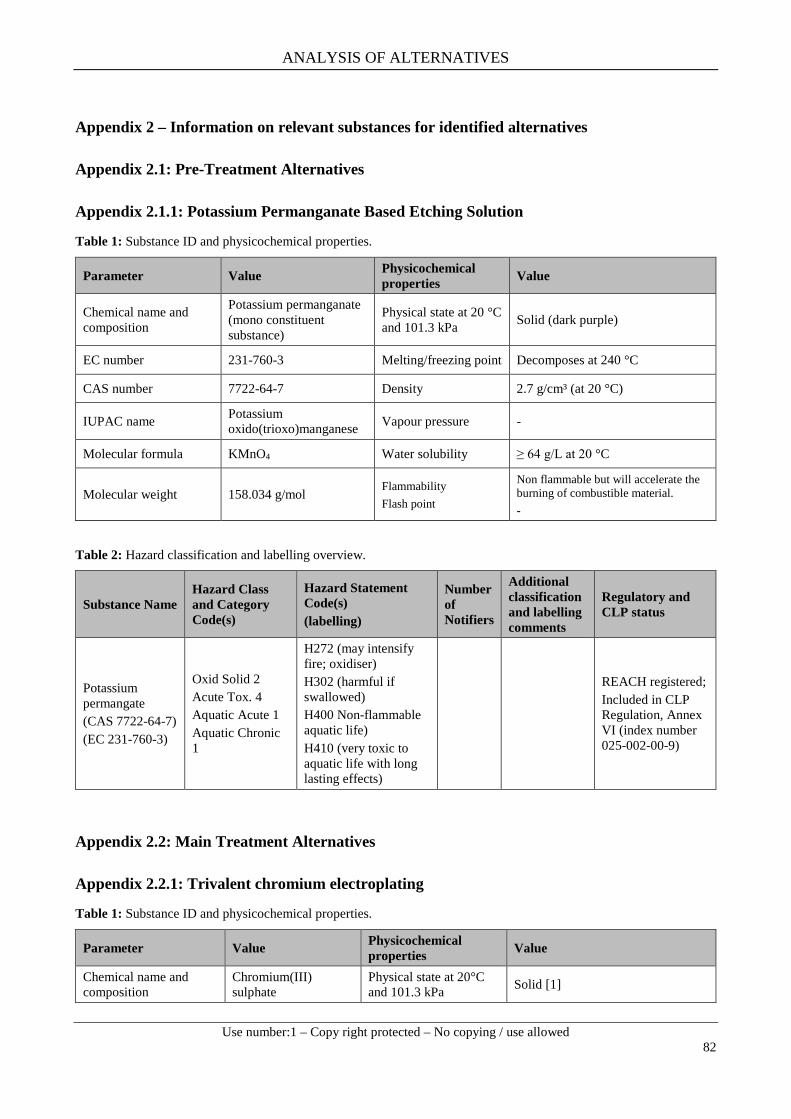
ANALYSIS OF ALTERNATIVES
Use number:1 – Copy right protected – No copying / use allowed
82
Appendix 2 – Information on relevant substances for identified alternatives
Appendix 2.1: Pre-Treatment Alternatives
Appendix 2.1.1: Potassium Permanganate Based Etching Solution
Table 1: Substance ID and physicochemical properties.
Parameter Value Physicochemical properties Value
Chemical name and composition
Potassium permanganate (mono constituent substance)
Physical state at 20 °C and 101.3 kPa Solid (dark purple)
EC number 231-760-3 Melting/freezing point Decomposes at 240 °C
CAS number 7722-64-7 Density 2.7 g/cm³ (at 20 °C)
IUPAC name Potassium oxido(trioxo)manganese Vapour pressure -
Molecular formula KMnO4 Water solubility ≥ 64 g/L at 20 °C
Molecular weight 158.034 g/mol Flammability Flash point
Non flammable but will accelerate the burning of combustible material. -
Table 2: Hazard classification and labelling overview.
Substance Name Hazard Class and Category Code(s)
Hazard Statement Code(s) (labelling)
Number of Notifiers
Additional classification and labelling comments
Regulatory and CLP status
Potassium permangate (CAS 7722-64-7) (EC 231-760-3)
Oxid Solid 2 Acute Tox. 4 Aquatic Acute 1 Aquatic Chronic 1
H272 (may intensify fire; oxidiser) H302 (harmful if swallowed) H400 Non-flammable aquatic life) H410 (very toxic to aquatic life with long lasting effects)
REACH registered; Included in CLP Regulation, Annex VI (index number 025-002-00-9)
Appendix 2.2: Main Treatment Alternatives
Appendix 2.2.1: Trivalent chromium electroplating
Table 1: Substance ID and physicochemical properties.
Parameter Value Physicochemical properties Value
Chemical name and composition
Chromium(III) sulphate
Physical state at 20°C and 101.3 kPa Solid [1]

ANALYSIS OF ALTERNATIVES
Use number:1 – Copy right protected – No copying / use allowed
83
Parameter Value Physicochemical properties Value
EC number 233-253-2 Melting point 90 °C [1]
CAS number 10101-53-8 Density 3.10 g/cm³ (anhydrous) [1]
IUPAC name Chromium(III) sulphate Vapour pressure -
Molecular formula Cr2(SO4)3 Water solubility Insoluble in water and acids (anhydrous). Soluble as hydrate [2]
Molecular weight 392.18 g/mol Flammability Flash Point
Non-flammable -
Parameter Value Physicochemical properties Value
Chemical name and composition
Chromium(III) chloride
Physical state at 20 °C and 101.3 kPa solid
EC number 233-038-3 Melting point ca. 1150 °C
CAS number 10025-73-7 Density 2.87 g/cm³ (25 °C)
IUPAC name Chromium(III) chloride Vapour pressure -
Molecular formula CrCl3 Water solubility 0.585 g/cm³
Molecular weight 158.36 g/mol Flammability Flash Point
Non-flammable -
Parameter Value Physicochemical properties Value
Chemical name and composition
Chromium trichloride hexahydrate
Physical state at 20 °C and 101.3 kPa Solid (green)
EC number n.a. Melting/freezing point [²] 80-83 °C
CAS number 10060-12-5 Density -
IUPAC name Chromium(III) chloride hexahydrate Vapour pressure
-
Molecular formula CrCl3 · 6H2O Water solubility 590 g/L (at 20 °C)
Molecular weight 266.45 g/mol Flammability Flash point
Non flammable -
Chemical name and composition
Boric acid (mono constituent substance)
Physical state at 20 °C and 101.3 kPa Solid (crystalline, odourless)
EC number 233-139-2 Melting/freezing point No melting point detected below 1000 °C
CAS number 10043-35-3 Density 1.49 g/cm3
IUPAC name Boric acid Vapour pressure 9.90 . 10-8 kPa (25 °C)
Molecular formula BH3O3 Water solubility 48.40 g/L (20°C, pH = 3.6)
Molecular weight 61.83 g/mol Flammability Non flammable

ANALYSIS OF ALTERNATIVES
Use number:1 – Copy right protected – No copying / use allowed
84
Parameter Value Physicochemical properties Value
Parameter Value Physicochemical properties Value
Chemical name and composition Ammonium chloride Physical state at 20 °C
and 101.3 kPa Solid (crystalline)
EC number 235-186-4 Melting/freezing point 340 °C (sublimation)
CAS number 12125-02-9 Density 1.53 g/cm3 (at 20 °C)
IUPAC name Ammonium chloride Vapour pressure -
Molecular formula ClH4N Water solubility 283 g/L (25 °C)
Molecular weight 53.5 g/mol Flammability Flash Point
Non flammable -
Table 2: Hazard classification and labelling.
Substance Name
Hazard Class and Category Code(s)
Hazard Statement Code(s) (labelling)
Number of Notifiers
Additional classification and labelling comments
Regulatory and CLP status
Chromium sulphate (CAS 10101- 53-8) (EC 233-253-2)
Not classified - 1,103
1,103 notifiers did not classify the substance.
Currently not REACH registered; Not included in the CLP Regulation, Annex VI; Included in C&L inventory
Chromium chloride (CAS 10025- 73-7) (EC 233-038-3)
Acute Tox. 4 H302 (Harmful if swallowed)
41
Additional 6 parties notified the substance as Acute Tox 4 (H302) only. Further 6 notifiers submitted the classification as Acute Tox 4 (H302) and Aquatic Chronic 3 (H412).
Currently not REACH registered; Not included in the CLP Regulation, Annex VI; Included in C&L inventory
Skin Irrit. 2 H315 (Causes skin irritation)
Eye Irrit. 2 H319 (Causes serious eye irritation)
Acute Tox. 1 H330 (Fatal if inhaled)
Chromium trichloride hexahydrate (CAS 10060- 12-5)
Skin Irrit. 2 Eye Irrit. 2 STOT SE 3
H 315 (causes skin irritation) H 319 (causes serious eye irritation) H 335 (may cause respiratory irritation)
30
REACH registered; Not included in the CLP Regulation, Annex VI; Included in C&L inventory
Acute TOX 4
H 302 (harmful if swallowed) 24
Not classified 5

ANALYSIS OF ALTERNATIVES
Use number:1 – Copy right protected – No copying / use allowed
85
Substance Name
Hazard Class and Category Code(s)
Hazard Statement Code(s) (labelling)
Number of Notifiers
Additional classification and labelling comments
Regulatory and CLP status
Boric acid (CAS 10043- 35-3) (EC 233-139-2)
Repr. 1B
H360FD (May damage fertility. May damage the unborn child)
n/a
REACH registered; Included in CLP Regulation, Annex VI (index number 005-007-00-2); Included according to Annex XVI on the candidate list (SVHC substance)
Ammonium chloride (CAS 12125- 02-9) (EC 235-186-4)
Acute Tox 4 Eye Irrit. 2
H 302 (harmful if swallowed) H 319 (causes serious eye irritation)
Harmonised classification- Annex VI of Regulation (EC) No 1272/2008 Included in CLP Regulation, Annex VI (index number 017-014-00-8);
Appendix 2.2.2: PVD-based processes
Table 1: Substance ID and physicochemical properties.
Parameter Value Physicochemical properties Value
Chemical name and composition
Titanium nitride (mono constituent substance)
Physical state at 20 °C and 101.3 kPa Solid (gold)
EC number 247-117-5 Melting/freezing point 2930 °C
CAS number 25583-20-4 Density 5.22 g/cm3
IUPAC name Titanium nitride Vapour pressure -
Molecular formula TiN Water solubility Insoluble in Water
Molecular weight 61.87 g/mol Flammability Flash Point:
Non flammable -
Parameter Value Physicochemical properties Value
Chemical name and composition Chromium nitride Physical state at 20 °C
and 101.3 kPa Solid (dark powder, odourless)
EC number 246-016-3 Melting/freezing point -
CAS number 24094-93-7 Density 5.90 g/cm³
IUPAC name [4] Azanylidylnechromium Vapour pressure -

ANALYSIS OF ALTERNATIVES
Use number:1 – Copy right protected – No copying / use allowed
86
Molecular formula CrN Water solubility Insoluble
Molecular weight 66.0 g/mol Flammability Flash Point:
- -
Parameter Value Physicochemical properties Value
Chemical name and composition Titanium carbonitride Physical state at 20 °C
and 101.3 kPa powder
EC number 603-147-4 Melting/freezing point > 350 °C
CAS number 12654-86-3 Density 5.08 g/ cm3 (at 25 °C)
IUPAC name Titanium carbonitride Vapour pressure n.a
Molecular formula CNTi2 Water solubility n.a
Molecular weight 121.75 g/mol Flammability Flash Point:
n.a n.a
Table 2: Hazard classification and labelling.
Substance Name Hazard Class and Category Code(s)
Hazard Statement Code(s) (labelling)
Number of Notifiers
Additional classification and labelling comments
Regulatory and CLP status
Titanium nitride (CAS 25583- 20-4 ) (EC 247-117-5)
Not classified
11 Notified Classification
Flam. Sol. 2 Skin Irrit. 2 Eye Irrit. 2
H 228 (flammable solide) H 315 (causes skin irritation) H 319 (causes serious eye irritation)
10
Titanium carbo nitride (CAS 12654- 86-3) (EC 603-147-4)
Not classified
According to suppliers MSDS this substance is not classified according to EG Nr. 1271/2008.
Chromium nitride (CAS 24094- 93-7) (EC 246-016-3)
Not classified
3 Notified Classification
ANALYSIS OF ALTERNATIVES
Use number:1 – Copy right protected – No copying / use allowed
87
Appendix 2.3: Sources of Information
Information on substance identities, physicochemical properties, hazard classification and labelling are based on online data searches. All online sources were accessed between June and September 2014. The main sources are:
- European Chemicals Agency: http://echa.europa.eu/de/ - ChemSpider http://www.chemspider.com - http://www.chemicalbook.com - http://pubchem.ncbi.nlm.nih.gov - http://www.scbt.com - Merck Safety Data Sheet: http://www.merck-performance-materials.com/ - Sigma Aldrich Safety Data Sheet: http://www.sigmaaldrich.com/ - http://www.sciencelab.com/msds.php?msdsId=9927079 - Alfa Aesar Safety Data Sheet: http://www.alfa.com/ - United States Environmental Protection Agency internet site: http://www.epa.gov - Carlroth Safety Data Sheet: http://www.carlroth.com/ - Fisher Scientific Safety Data Sheet: http://www.fishersci.com - Carl Roth Safety Data Sheet: http://www.carlroth.com/media - www.nyltek.com/pdf/SAFETY.pdf

ANALYSIS OF ALTERNATIVES
Use number:1 – Copy right protected – No copying / use allowed
88
Appendix 3 – OEM specifications
Confidential business information
ANALYSIS OF ALTERNATIVES
Use number:1 – Copy right protected – No copying / use allowed
89